环球立式插件机6380B-8XT资料
- 格式:pdf
- 大小:1.33 MB
- 文档页数:4
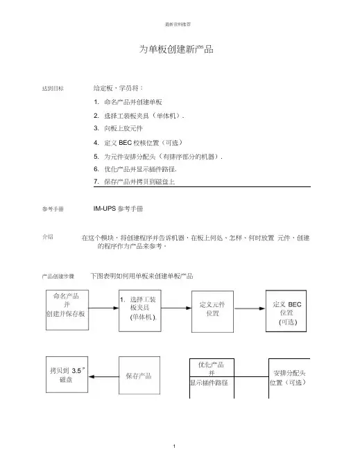
优化产品并安排分配头 显示插件路径位置(可选)为单板创建新产品达到目标给定板,学员将: 1. 命名产品并创建单板 2. 选择工装板夹具(单体机). 3. 向板上放元件4. 定义BEC 校核位置(可选)5. 为元件安排分配头(有排序部分的机器).6. 优化产品并显示插件路径.7. 保存产品并拷贝到磁盘上参考手册IM-UPS 参考手册在这个模块,将创建程序并告诉机器,在板上何处、怎样、何时放置 元件,创建的程序作为产品来参考。
介绍产品创建步骤下图表明如何用单板来创建单板产品命名产品并创建板介绍必须为机器编程以使元件在希望的位置插入,在 IM-UPS 中,此程序被 参考作为产品。
对于那些熟悉 PPU 编程的人来说,一个产品就象旧的.PUT 、.MAG 、以及.ERV 程序的组合。
将会看到,新的编程方法 IM-UPS 与旧的编程方法PPU 有很多区别,在进行这个模块时将提到。
创建板在创建产品之前,首先必须定义为其写程序的板的尺寸,这是 IM-UPS与PPU 的一个主要区别。
因为IM-UPS 是图形界面,所以首先必须定义一个 图形区域”来与计算机相联系。
例如,如果想在3” x3的板上插入元件,就必须向计算机输 入这一数据,负责计算机将不知道这些元件应该去哪里。
一个好的分析 方法是,当你想画一个上面有元件的完整的 PCB 时,你首先需要有一页 纸。
产品编辑器中的板就是你想画元件的那页纸。
注意:贯穿整个产品编辑器,可以用F4功能键返回前一动作,这非常有用,因为我们都会 犯错误!1. 我们将手动创建板,PC 板是方形的(实际上是正方形)。
在IM-UPS 主屏上,点击 Product Editor Icon .产品编辑器图标练习: 创建板最新资料推荐1从菜单栏选择Board (板),然后选择Create/Edit.(创建/编辑)2. 在图框内输入板的长度和宽度,长度 (千分之一英寸单位)测量沿着 机器的X 轴,宽度沿着丫轴。

RADIAL RADIAL 88XT XT((63806380B B )说明书RADIAL RADIAL 88XT XT((63806380B B )说明书目录第一部分 设备电第一部分 设备电、、气及场地要求第二部分 设备机械组成部位介绍第三部分 设备安全标识及安全操作方法第四部分 设备第四部分 设备OS OS OS//2、IMUPS IMUPS系统介绍系统介绍第五部分 设备编程方法第六部分 设备机械部件调校方法第七部分 设备对第七部分 设备对PCB PCB PCB的工艺要求 的工艺要求第八部分 设备易损件表一>场地要求:1>电压:220+10VAC/55+10HZ 2>空气开关电流: 15-20A 3>机器功率: 2.7KW-3.4KW 4>气压: 90PSI 或6千克5>6>气管内直径: 13MM 7>电线要求: 4-6平方8>车间温度: 22-26度9>湿度:50-60%1>L1机头长:1.6M 2>L2机头宽:1.8M 3>L3机尾长(20站):1.6M (每增加20站增加1M)4>L4机尾宽:1.5M 5>L5整机长:3.2M 6>机器高度:1.7M7>机器两侧:M1`M2>1.0M 机尾M3>1.0M 机头M4>2.0M二>机器尺寸:第一部份 设备场地要求及电第一部份 设备场地要求及电、、气、机器尺寸第二部份 设备机械组成部位介绍1、分配头与链条2、计数器3、剪切站4、分配头5、分配头感应6、链条马达7、操作面板开头8、CTA部件8、X、Y轴定位系统9、BEC定位系统10、剪脚头14、元件抛料站11、插件头12、元件出现检测器13、修复元件指示灯第三部分 设备安全标识及安全操作方法一、二、8>生产中有紧急情况须按下急停开关等候技术人员处理7>严禁机器在无人操作下自动运行三、安全门感应器位置及安全操作注意事项3>机器生产中不可以碰到安全门 4>机器生产中不可拉开安全门5>生产中严禁在机器盖上放任何硬物或杂物 6>生产中严禁进入系统中修改参数 2>严禁两人操作一台机器各开关及按健 1>机器在生产中不可将手、工具放在移动台上Palm Switch 紧急停止安全门感应器安全门感应器安全门移动工作台移动工作台第四部分 设备第四部分 设备OS OS OS//2、IMUPS IMUPS系统介绍系统介绍将此开关转到ON位置,机器处于手动状态可进行维修保养或更换一、操作面板(各功能键位置)STOP 停止START开始PalmSwitch 紧急停止OVERRIDE/TRANSFER ERROR 连续运行INTERLOCK RESET 恢复联锁INTERLOCK BYPASS维修/手动/自动方式SYSTEM SETUP (系统设定):设系统各项参数PRODUCT EDIT(产品编辑):进入产品程序编辑PRODUCT CHANGEOVER(产品转换):从不同路径导入产品程序PRODUCTION CONTOL(生产控制):进入手动控制状态MACHINE STATUS(机器状态):显示当前机器所处状态MANAGEMENT INFORMATION(管理资料):记录显示产品生产报告 DOCUMENTS(资料):机器有关说明文件IM DIAGNOSTICS(系统诊断):进入控制系统各参数校正及故障检修二、电脑控制屏各功能键SETUP(IMUPS设定):进入IMUPS操作系统设定SECURITY(安全):进入密码设定MAINTENANCE INTERVAL SERVICE(保养进度):进入保养进度表SHUTDOWN(关机):机器不做生产时关闭系统OS/2 WINDOW(OS2窗口):进入DOS菜单TURN OFF ALARM(关闭警报):遇到有警报声需点击做消除机器做分解动作机器做单步动作机器做连续动作显示产品内容显示生产信息显示物料站位情况LOAD PRODUCT(导入产品):导入新产品程序CHANGE PRODUCT COUNT(改变产品数量):在生产中修改所须生产产品的数量 FILE MANAGER(文档管理):管理各种文档插件头已启动工作1>点击电脑上 2>在Requested Count 中设定产品数量,点击FullCycle3〉在Products defined 中选择产品程序,接着点击OK产品程序已导入4>确认物料已装好后,将各安全门、盖关好5〉旋开拉起开关灯灭,接着按6>待机器归零结束后,将待生产的PCB板放到机器夹具上,再次按机器开始工作自动插件LOAD PRODUCT 图标出现上图三、导入产品程序进行生产方法点击FULLCYCLE1>开机a>先打开UPS电源,按POWER ON开关b>将机器后面电源开关OFF转到ONC>待机器电脑出现Initializtion complete 后开机完成开关b>用鼠标点击图标,出现右边提示选择YES C>将机器后面电源开关ON转到OFFd>关闭UPS电源,按POWER OFF开关四、关机操作方法STOP停止START 开始Palm Switch 紧急停止OVERRIDE/TRANSFER ERROR连续运行INTERLOCKRESET恢复联锁INTERLOCK BYPASS维修/手动/自动方式第五部分 设备编程方法A>length:xxx B>width:xxx图二4>在Template选择Save As(输入名称)选择OK即可5>在Board Thickness中输入PCB板厚度(如下图)选择OK即可B >Width Width((元件实际宽度元件实际宽度):):):((XXX XXX))mmC >Height Height((元件高度元件高度))(XXX XXX))mm1 1> > > 选择元件种类选择元件种类选择元件种类((如LEDS LEDS- - - Rad Rad Rad))2 2> > > 进入进入进入Component Component Component进行如下操作进行如下操作进行如下操作((如下图如下图) )3 3>>设定 设定 Body infornation Body infornationA >Length Length((元件实际长度元件实际长度):):):((XXX XXX) ) ) mm mm第二步>进入主菜单Components 中点击 Database6241F主菜E >polarized components polarized components((元件极性元件极性):):):YES YES YES/+/-//+/-//+/-/NO NOD >lead diameter lead diameter((元件脚实际直径元件脚实际直径):():():(xxx mm xxx mmA> Product Nome中输入程式名B> board中选入PCB尺寸(UIC设备生产程序制作方法-设定的PCB尺寸) C>选择OK1>在主菜单中执行Product Product Product点击点击点击New New2>在Nnew Product Nnew Product Nnew Product 中执行以下操作中执行以下操作中执行以下操作((如下图如下图))C>在Y POS 中输入Y坐标(用卡尺量)D>在Theta 中输入插件时的角度(0/90/180/270)E>在hole span 中输入插件时元件跨度(用卡尺量)F>在depth stop 中输入插件时元件高度(用卡尺量)1>在主菜单Components omponents omponents中点击中点击中点击Lnsertion List Lnsertion List Lnsertion List((如上图如上图))2>在Lnsertion List菜单中执行以下操作(如上图)G>在anvil span offset 中输入03>完成以上步骤即做好一个元件,重复以上步骤依此做出PCB上需插件的元件(如下图A>在component ID 中选择要插件元件类型(如:跳线/电阻/二极管)B>在X POS 中输入X坐标(用卡尺量)第五步:设定元件物料站位Dispense Heads1>在主菜单中选择Dispense Heads2>在Dispense Head List中输入元件分配的站位序号(如下图)第六步:程式名优化(根据实际需要操作)1>在主菜单中选择Order中点击Optmization(如下图)2>在Optimizetion optione中选择双下操作来完成优化(如下图3>在主菜单中选择save即完成程序制作第六部分 设备机械部件调校方法一、二、三、四、五、六、七、八、九、十、十一、十二、十三、十四、十五、十六、十七、十八、十九、第七部分 设备对PCB的工艺要求一、PCB工艺边设计(设备单窗口打板设计参考):板边为8.00MM板宽≤407.00MM板边为5.0MMAAB B 定位孔直径3.0+0.05MM(或椭圆5.0×3.0MM)定位孔中心离PCB板右边缘(A)5.0MM、离PCB板外边缘(B)3.5MM定位孔直径3.0+0.05MM、定位孔中心离PCB板左边缘(A)5.0MM、离PCB板外边缘(B)3.5MM二、PCB工艺边设计(设备双窗口打板设计参考)板边为8.0MM板宽≤170.00MM板边为8.0MM板长≤508.00MM定位孔直径3.0+0.05MM(或椭圆5.0×3.0MM)定位孔中心离PCB板右边缘(A)5.0MM、离PCB板外边缘(B)定位孔直径3.0+0.05MM、定位孔中心离PCB板左边缘(A)5.0MM、离PCB板外边缘(B)3.5MM AB A B四、不规则的PCB板须合成规则PCB板设计:第八部分 设备易损件表。


AIR DATA ACCESSORIES KITMODEL No. DH8-834M DASH8-100/200/300/400AIRCRAFTTo buy, sell, rent or trade-in this product please click on the link below:https:///Nav-Aids-Ltd-DH8-834M-Air-Data-Accessory-Kit-for-Dash-8-100-200-300-400-Aircraft.aspxAIR DATA ACCESSORIES KITMODEL No. DH8-834MDASH8-100/200/300/400 AIRCRAFTApril 14, 2009Page 2 of 3This kit contains all the equipment required to test from source the complete pitot & static air data system on the Dash 8-100/200/300/400 aircraft, as well as the means of pre-testing all adaptors and hoses prior to being fitted to the aircraft.Pitot Test AdaptorPart No. P22201-3 (2 req’d.) (Dash 8-100/200/300)These units fit the pitot probes P/N PH1100-1DH located on each side of the aircraft and when installed they will isolate and test each system separately orsimultaneously, using pitot hose assembly supplied. Pre-Test ProbePart No. PT11882 (2 req’d.) (Dash 8-100/200/300)When it becomes necessary to test the integrity of the pitot test adaptors and/or hoses and test set, these units are installed into the pitot test adaptors thus simulating the pitot head.Static Test Adaptor Part No. S51089-4 (1 req’d.) (Dash 8-100/200/300)This unit fits the Captain’s, F.O. and alternate static ports on the aircraft. This is a composite static vent.N.B. Attach the hose to unit before installing on aircraft.Static Blanking Adaptor Part No. S51089B (1 req’d.) (Dash 8-100/200/300)This unit is used in conjunction with theabove mentioned test adaptor and is used to blank off the matching static vent on the opposite side of the aircraft. A test port is provided on the unit should it be desirable to check the integrity of the unit. Static Pre-Test Plate Part No. PT14097 (2 req’d.) (Dash 8-100/200/300)These units are mounted onto the case cover and also act as storage pad. Before testing the integrity of the static test adaptors ensure that the mounting bolts are tight. The static testing and blanking adaptors may be tested separately or as a pair by connecting with the static hose assembly DH-7270CB. Pitot & Dual Static Test Adaptor Part No. PSS22202M-3-4-4 (2 req’d.) (Dash 8-400)These units fit the pitot probes P/NC14135DA & C14135CA located on the nose and when installed they will isolate and test each system separately or simultaneously. Pre-Test ProbePart No. PT421-202M (2 req’d.) (Dash 8-400)When it becomes necessary to test theintegrity of the pitot & dual static test adaptors and/or hoses and test set, these units are installed into the adaptors thus simulating the pitot head.AIR DATA ACCESSORIES KITMODEL No. DH8-834MDASH8-100/200/300/400 AIRCRAFTApril 14, 2009Page 3 of 3Pitot Static Adaptor - Standby Part No. PS22203M-3-4 (1 req’d.) (Dash 8-400)This unit fits the pitot static probe, P/N C16193BA, located on the nose of the aircraft. Pre-Test ProbePart No. PT421-203M (1 req’d.) (Dash 8-400)When it becomes necessary to test theintegrity of the pitot static test adaptor and/or hoses and test set, this unit is installed into the adaptor thus simulating the pitot head. Pitot Test Hose Assembly Part No. DH-7270CB (1 req’d.) (Dash 8-100/200/300/400)This hose is connected to each pitot inlet of the adaptors and is fitted with double acting quick disconnects for use when it is desirable to test only one pitot system. The connection for the pitot outlet of the pneumatic generator is included on this assembly. Static Test Hose Assembly Part No. DH-5160CB (1 req’d.) (Dash 8-100/200/300/400)This assembly attaches to the static fittings. The double acting quick disconnects operate in the same manner as that on the pitot test hose assembly. The extension fitting then connects to the static outlet hose of the pneumatic generator.Lubricating Fluid Part No. LF5050 (1 req’d.)This fluid is used to lubricate the glands of the pitot & dual static and pitot static test adaptors. It is recommended that a small amount be used before installing adaptors on pitot head to ensure smooth installation onto the pitot probe.Seal Kit - Part No. SK201Two sets of spare seals for pitot test adaptors P/N P22201-3 are stowed in the case. Seal Kit - Part No. SK202MTwo sets of spare seals for pitot & dual static test adaptors - P/N PSS22202M-3-4-4 are stowed in the case. Seal Kit - Part No. SK203MOne set of spare seals for standby pitot static test adaptor - P/N PS22203M-3-4 is stowed in the case.Manual - Part No. 444-DH8-834 One manual is supplied with each kit. The equipment is enclosed in a case assembly - Model No. 110XD-DH8-834.。

外挂式机柜空调操作及使用说明书1 手册提示 (5)2 搬运 (5)2.1 运输 (5)2.2 储运 (5)2.3 开箱 (5)3 供货范围 (6)4 一般信息 (6)5 铭牌 (6)6 安全 (7)7 功能 (7)7.1 配置与功能 (7)7.2 工作原理 (7)7.3 冷凝物 (8)8 技术规格书 (8)8.1电气原理图 (8)8.2备品备件 (9)8.3安装开孔 (9)8.4气流原理 (12)8.5技术参数 (12)9 安装 (16)9.1 概述 (16)9.2 安装工作 (16)9.3 电气连接 (17)10 运行条件 (17)11 投入使用和功能 (17)11.1 概述 (18)11.2 操作显示器 (18)11.3启动测试模式 (18)11.4 门触点 (18)11.5 设备故障 (19)12 参数查看与设置 (19)13 清洁和维护 (20)13.1 清洁 (20)13.2 维护 (20)14 停止使用 (21)15 故障排除 (21)16 保障条款 (21)附表I (22)1 Hints on the manual (23)2 Handling (23)2.1 Transport (23)2.2 Storage (23)2.3 Unpacking (24)3 Scope of delivery and options (24)4 General Information (24)5 Name plate (24)6 Safety (25)7 Function (25)7.1 Function and configuration (25)7.2 Operating principles (26)7.3 Condensate (26)8 Technical data (27)8.1 Circuit Diagram (27)8.2 Spare parts (28)8.3 Installation Cut-out (28)8.4 Airflow principle (31)8.5 Technical Data (31)9 Installations (35)9.1 General (35)9.3 Electrical connection (36)10 Operating condition (37)11 Putting into operation and function (37)11.1 General remarks (37)11.2 Operation display (37)11.3 Start-up / Test mode (38)11.4 Door contact (38)11.5 Equipment fault (38)12 Parameters View and Settings (39)13 Cleaning and Maintenance (40)13.1 Cleaning (40)13.2 Maintenance (40)14 When not in used (40)15 Trouble shooting (41)16 Warranty Conditions (41)Appendix I (42)1 手册提示此手册为百能堡电气科技有限公司(以下简称百能堡)提供的门装或侧装螺栓固定,外挂式机柜空调系列的安装运行指南。

SMT设备性能参数对生产基本的工艺要求针对在实际的生产中设备与工艺的可制造性出现的冲突异常,现将一些在实际操作中常使用及注意事项的要求参数整理汇总,同时将经常出现的一些工艺上要求汇总与大家分享一下以便我们共同努力提高制程能力,详细如下:AI设备参数要求:SMT设备参数要求:二:550mm*650mm网框,铝框厚度25.4mm,铝框宽度38.1mm。
三:29*29英寸,网框尺寸736mm*736mm,铝框厚度40.00mm,铝框宽度40.00mm。
制程中不良案例分析及改善措施一、自动插件时,发现供料的MZ31-04M 400-500Ω热敏电阻出现引脚断裂的不良现象(见附图)。
引脚插件时断裂对自动插件设备造成损坏隐患;且从引脚断裂面分析,部分物料可能存在电性能不良可能原因:从提供的图片来分析为表面受力,工序周转时个别产品受到撞击,本体所承受的拉力较小,易断;测阻值时没有能对已受到的外力的产品测出。
措施:焊接工序增加外观全检,工序周转时由专人操作避免粗暴作业;控制锡炉的温度每小时做到点检,由QC及生产小组长监督与抽查;阻值测试现调整为全检;对员工培训。
二、发现FR105编带脱胶严重,影响机插:产生不良的原因有以下两种可能:1、在后道编带过程中,由于操作人员调试不当,没有将机器的压轮调节到位,从而使该批编带由于没有压紧,在运输过程中的受到各种力作用使得编带松动、脱胶。
2、该批次的编带粘性不良。
改善控制措施:1、对于原因一,我们对作业记录及同一机器当天其它批次的产品进行检查,并没有发现任何异常。
2、对于原因二,由于我司IQC对编带粘性没有检验手段,我们已经与供应联系,让其分析产生不良的原因,并进行整改。
3、针对我司目前对编带粘性没有检验手段这一情况,我司已经组织相关人员进行制定,目前工作正在进行中。
三、使用过程中发现有一盘二极管存在本体不齐的现象;原因:主要是胶带粘合不紧密造成。
四、引脚从根部脱焊断裂在自动插件生产时,发现供料的RY 2W301 J 编带小型电阻在引脚打弯时有引脚从根部断裂的现象,查看引脚断口可以看出引脚端部未形成良好焊点(见附图)。

精品资料环球插件机(U n i v e r s a l)6380B调试........................................环球插件机6380B调整剪纸片器(Cutter Station)与链夹(CarrierClip)对中调节前提调整:链条时序(Chain Tension)已调整调整步骤:1、选择IM Diagnostics>Machine Setup>Critical AxisSetup;2、在Sequencer Chain窗口中,单击Zero按钮;3、待回零后,HP(HomePulse)字样应显示出来,检查剪纸片器与链夹的对中;4、如果剪纸片器中心与链夹“V”字形槽对中良好,单击Quit,Don’t Save Positions按钮,退出IM Diagnostics窗口;5、如果对中有偏差,松开链条编码器两个固定螺丝,转动编码器以调整剪纸器与链夹的对中,正确后拧紧两螺丝,单击Quit,Don’tSave Positions按钮, 退出IM Diagnostic窗口。
插件头角度(Head ThetaAxis)设置调整前提准备:1、插件头角度(HeadTheta),垂直(Vertical),推杆(Insert)伺服电机均不带电2、X与Y轴伺服电机不带电特殊工具:1、插件头/底座(Head/Clinch)对中工具2、BEC调整模板注释:插件头角度“0”度调整好后,+90,-90度位置将自动调整正确调整步骤:1、选择IM Diagnostics>Machine Setup>Critical AxisPositions;2、手动升高垂直感应螺丝以使其距垂直上极限感应开关约1英寸(25.4mm);3、在Head Theta窗口中,单击Zero按钮;4、在Head Theta窗口中,单击Disable按钮;5、拆卸插件头并装上插件头/底座对中工具;6、装上BEC调整模板;7、向前推动工作台或降低插件头对中工具(此时应为“0”度)使BEC调整模板与对中工具齐平;8、在Head Theta窗口中At 0(R)行,单击Set按钮;9、向后拉动工作台并拆卸插件头对中工具;10、在主窗口中,单击Exit,Save these Positions按钮。
T4.64寸6单元全频专业扬声器T系列全频专业扬声器系统产品说明书CN UM-T4.6-20090507 v e r A感谢您购买 产品!请仔细阅读本手册,它将帮助你妥善设置并运行您的系统,使其发挥卓越的性能。
并保留这些说明以供日后参照。
警告:为了降低火灾与电击的风险,请不要将产品暴露在雨中或潮湿环境中。
警告:为了降低电击的风险,非专业人士请勿擅自拆卸该系统。
仅供专业人士操作。
等边三角形中的闪电标记,用以警示用户该部件为非绝缘体,系统内部存在着电压危险,电压。
可能足以引起触电。
可能足以引起触电如系统标有带惊叹号的等边三角形,则是为提示用户严格遵守本用户指南中的操作与维护规定。
注意:请勿对系统或附件作擅自的改装。
未经授权擅自改装将造成安全隐患。
警告:燃不得将明火源(如点的蜡烛)放在器材上面。
1. 请先阅读本说明。
2. 保留这些说明以供日后参照。
3. 注意所有警告信息。
4. 遵守各项操作指示。
5. 不要在雨水中或潮湿环境中使用本产品。
6. 不要将产品靠近热源安装,例如暖气管、加热器、火炉或其它能产生热量的装置(包括功放机 )。
7. 不要破坏极性或接地插头的安全性设置。
如果提供的插头不能插入插座,则应当请专业人员更换插座。
8. 保护好电源线和信号线,不要在上面踩踏或拧在一起(尤其是插头插座及穿出机体以外的部分 )。
9. 使用厂商规定及符合当地安全标准的附件。
10.雷电或长时间不使用时请断电以防止损坏产品。
12. 不要让物体或液体落入产品内——它们可能引起火灾或触电。
13. 请注意产品外罩上的相关安全标志。
. 仅与厂商指定或与电器一同售出的推车、架子、三脚架、支架或桌子一起使用。
推动小车/电器时,应谨防翻倒。
11注意事项产品的安装调试须由专业人士操作。
在使用非本厂规定的吊装件时,要保证结构的强度并符合当地的安全规范。
警告:1扬声器及扬声器系统的产品有限保修期为自正式购买日起的3年。
由于用户不合理的应用而导致音圈烧毁或纸盆损坏等故障,不包含于产品保修项目。

CLAMP ON EARTH TESTERFT6380, FT6381For multi grounded systems onlyEasy pole earth resistance measurement with super slim jaw0.02 Ω to 1600 Ω wide measurement range for earth resistance measurement 1.00 mA to 60.0 A covering small leakage current to load currentEasy Open Jaw Light WeightHigh AccuracyPhone************Fax: 033 30222923************************0.87 inch(22 mm)2Get Things Done with Super Slim JawsEasy clamping!Open jaws easily with just two fi ngers.Only half the grip power is needed compared totypical clamp earth testers.Clamp at the narrowest point!Now you can easily clamp the earth cable on the polewithout digging. The dramatically slim 0.79 inch (20mm)jaws let you finish your job easily and effi ciently.No wait time after powering on.Start measuring instantly without zero-calibration.LCD with beautiful back lightWith the bright back light, you can easilyread the measurement value even in darklocations.Large storage capacity(up to 2,000 data)You can store up to 2,000 measurementvalues in the fi eld and recall them in youroffi ce later.Filter function enables evenmore accurate measurementsResistant mode filter: digital filter givesyou steadier readings.Current mode filter: Low-pass filtereliminates harmonics current over 180Hz. Quick Start!Alarm FunctionSet the alarm to audibly and visually notifyyou that the resistance or current valueexceeds the threshold.0.87 inchHigh Accuracy and RepeatabilityWell-designed magnetic shields eliminatethe leakage fl ux between the two cores thatoften affect measurement accuracy.1.5 inch1.26 inch(32 mm)(22 mm)(20 mm)(38 mm)Memory numbe r+++3Measurement PrincipleFT6380/6381 can measure Multi-Grounded systems.Voltage InjectionCurrent MeasurementRx R1R2R3R4Clamp on the earth cable. The instrument has two cores for voltage injection and current measurement.1. The voltage transducer injects a defi ned voltage into the multi-grounded system.2. From the defi ned voltage and measured current, the total circuit loop resistance is calculated in thefollowing equation.In a typical multi-grounded system, the parallel resistance value is small enough to be ignored and the equation as referredabove can be simulated as follows.Rx =VIAutomatic Report GenerationModel FT6381 can create reports instantly in the fi eld usingan Android TM phone via a Bluetooth® wireless technology.1111R1 R2 R3 R41Rx +VI=Offi ce. . .After making a report, you can see it onthe Android TM phone or send the datato your PC at the offi ce via e-mail.Real time data transferVia e-mailAutomatic Report Generationon your Android TM phoneReport includes the MeasurementValue, Date and Time, Map with GPSinformation and Pass/Fail information123Download dataAll information correct as of May. 22, 2012. All specifications are subject to change without notice.FT6380E2-25M Printed in JapanNote: Company names and Product names appearing in this catalog are trademarks or registered trademarks of various companies.Current ModeSpecificationsDisplayDigital/ LCD, max. 2000 digits Display update rate: 2 times / s Maximum conductor diameter formeasurementø 32 mm (1.26 in)Power supplyLR6 alkaline battery × 2Continuous operating time35 hours With display backlight off, Bluetooth OFF (FT6381)Auto power savePower save state when 5 minutes have elapsed since the last operation Operating temperature and humidity -10°C (14°F) to 50°C (122°F), 80 % rh or less (no condensation)Storage temperature and humidity (no condensation, except batteries)-20°C (-4°F) to 60°C (140°F), 80 % rh or lessDustproof and waterproof IP40 (EN60529) With Jaws ClosedTemperature characteristicsIn -10°C (14°F) to 50°C (122°F) range: add 0.1 × Measurement accuracy / °C Withstand voltage AC 7400 Vrms for one minute Between clamp sensor and casingMaximum input currentAC 100 A continuous, AC 200 A 2 minute (50 / 60Hz)Applicable standards Safety: EN61010 EMC: EN61326Dimensions, MassApprox. 73 mm (2.87 in) W × 218 mm (8.58 in) H × 44 mm (1.73) D , Approx 650 g (22.9 oz)AccessoriesCarrying Case×1, Resistance Check Loop×1, Strap×1, Instruction Manual×1Alkaline Battery(LR6)×2FT6381 InterfaceInterfaceBluetooth ® v2.1+EDRCommunication Distance 10 m (Class 2.1)Communication Protocol SPP (Serial Port Profile)CompatibilitySmartphone/ Tablet (Android TM )Applicable OSAndroid TM 2.1 or later Accuracy guaranteed for 1 yearResistance modeAccuracy guaranteed for 1 yearResistance Check Loop Carrying CaseAccessoriesBluetooth is a trademark of Bluetooth SIG, Inc. and licensed for use by HIOKI E.E. CORPORATION.Industrial Supply Syndicate54, Ezra Street, Kolkata - 700 001, INDIAPhone: 22350923, 22356676 Fax: +91 33 30222923Email:*******************************:。

DPST-8000M Pitot Static Test Set“Exceeds RVSM High Accuracy Standards”Cage Code # 3PTA2General InformationT he Model DPST-8000 Pitot Static Test Set is a precision test set with dual channel pressure controller, designed to provide regulated total (PT) pressure and static (PS) pressure outputs to simulate Altitude, Airspeed and Vertical Speed param-eters. The test set can also be used in a laboratory environ-ments to calibrate Altimeters, Airspeeds and ADC’s in maintenance shops or in harsh hangar environments. The test set is compact, light weight and has aremovable storage lid, which can fit in theoverhead compartmenton a commercialairliner.• Ports have self sealing quick connections, which are color coated and keyed to protect the aircraft and test equipment from pressure loss or incorrect system connections.• Internal pumps produce pressure and vacuum, which fill holding tanks for quick start ups and high performance rates. Exceeds 60,000 ft. of altitude, 15,000 ft./min VSI rate and 650 knots of airspeed.• Certified to perform Reduced Vertical Separations Minimum on fixed or rotary wing aircrafts.• Precision microprocessor based with Honeywell sensors, accuracy to 0.001% of full range.• Sun-light readable color TFT display showing real instrument EFD presentation.•The simple pop-up screens display the Altitude, Vertical Speed, Airspeed EPR and other measurements in various units of measure, including Ft, M, Kts, Km/hr, Mach, Ft/min, M/min, EPR (Pt/Ps), inHg, mb and psia. All readings are up-dated every 2 tenths of a second.• Automatic pitot and static leak rate modes automatically perform calculations & system failures.•Precision metering valves with protection shut off seats for maximum control rates.Standard Features Dimensions 20”L x 16”W x 8”H 25 lbs.• Water resistance and temperature corrected for extreme flightline conditions.• Smart AC power supply for safe flight line usage input voltages 85 to 264 V AC / 47 to 440 Hz• Storm Case constructed meets all applicable requirements of MIL-STD-810 removable lid, with fixed storage bag and watertight standards to MIL-108.• Test set is equipped with quick connect fittings and 2 hoses thatare each 20 ft in length.•Calibration meets or exceeds the published specifications,which are traceable to the National Institute Standards andTechnology “N.I.S.T.”.To buy, sell, rent or trade-in this product please click on the link below:/DFW-Instruments-DPST-8000M-Manual-Digital-RVSM-Air-Data-Test-Set.aspxDigital Manual RVSM Pitot Static Test Set DPST-8000M Performance SpecificationsAbsolute Pressure PerformanceStatic Pressure:Range: 0.3 to 40 inHg abs.Accuracy: +/- 0.001 inHg FS Repeatability: +/- 0.0008 inHgDrift: +/- 0.004 inHg per year FS Overpressure: 300 % FS without damagePitot Pressure:Range: 0.8 to 80 inHg abs.Accuracy: +/- 0.001 inHg FS Repeatability: +/- 0.002 +/- 100 ppm/yearDrift: +/- 0.01 inHg per year max. Overpressure: 300 % FS without damage Altitude PerformanceRange: -2000 ft. to 55,000 ft. Resolution: 1 ft.Accuracy: ±2 ft. @ 0 ft.±5 ft. @ 35,000 ft.±12 ft. @ 55,000 ft.Rate of Climb PerformanceRange: 100 ft./min. to 20,000 ft./min. Resolution: 1 ft./min.Accuracy: ±1 % of rate with a min. of 10 ft./min. Airspeed PerformanceRange: 10 to 600 KnotsResolution: 0.5 KnotsAccuracy: ±0.5 Knots@ 20 knots±0.05 Knots @ 600 knotsMach PerformanceRange: 0.0 Mach to 5.0 Mach Resolution: 0.001 MachAccuracy: 0.01 Mach above 0.1 Machfor Ps = 29.921 InHg.EPR PerformanceRange: 0.1 to 3.0 (Ps @ 30inHg) Resolution: 0.001Accuracy: 0.05 %FS PSI Pressure MediumDry AirPressure ConnectionsQuick Disconnects (2 ea.)Safety Seal on Female Quick ConnectDisplay Update RateOnce Every 2 Tenths per SecondOutputsUSB Port / Data Output / RS-485 (Additional Fees) SensorsHoneywell Certified Sensors (NIST Traceable)Power RequirementInput Range: 85 - 264 V ACFrequency Range: 47 Thru 440 Hz Environmental SpecsTemp. Operating: 0° C to +50° CTemp. Storage: -25° C to +60° C Humidity: 0% to 95% RH20 Warranty & CalibrationWarranty: 2 years (parts & labor) Calibration: Up to 1 year (yearly calibration suggested) RVSM CertificationCalibration / Trace to NISTExceed RVSM Accuracy Compliance Specs Physical Dimensions20” L x 15” W x 7“H Mil-STD810FWeight Case23 Lbs. Storm CaseORDERING INFORMATIONMfg. Part Number: DPST-8000M Accessories Include: Protection Quick Release Fittings, Hoses, Shipping Container and Operation Manual.。
6360E基本知识(精装版)6360E一、DI指令(DI 7)1 0° shot pin 插件头控制三个方向的pin10 90°shot pin R(右)100 90°shot pin L(左)1000 PART UNLOADER (链条后面推废料)10000 HEAD DRLVE EXTEND (头插下)100000 LNDEX CHAIN (链条运行)1000000 ANVIL EXTEND (剪脚头上)10000000 CLINCH (剪脚)100000000 CUTTER EXTEND (切纸皮CUTTER STATION)1000000000 INSERT 1 (压料缓冲汽缸)10000000000 COMP TRANS TO HEAD (CTA出来)100000000000 TEST HEAD EXTEND1000000000000 不用10000000000000 PART MISSING (料夹来料检测)100000000000000 CLINCH ROT +90°(剪脚头D方向转动N头)1000000000000000 CLINCH ROT -90°(剪脚头F方向转动N头)二、I/O箱各卡作用1、CPU(J11):主要操控整台设备运作2、P1:连接CPU,传送信号到SEQ I/O箱3、P3:控制各触点开关,包括转台下两个感应开关和有小电路板控制的开关4、P4:控制各感应开关,(无外加小电路板控制)及剪脚12VDC检测5、P5:控制元件来料检测,即料夹来料6、P7:控制电磁阀7、P8:控制元件插件不良显示8、P11:控制BEC自动跟踪9、P12、P13:X、Y马达、解码器信号反馈10、P17、P19:X、Y马达驱动卡三、直流电源箱保险丝作用1FU(10A)保护电源供应器和沿线相关装置2FU(1A)保护风扇、面板装置3FU(3A)保护36VDC(1T)变压器初级线圈,X、Y轴驱动马达4FU(2A)保护24VDC(2T)变压器初级线圈和沿线相关装置,5FU(6.25A)保护24VDC(2T)变压器次极线圈及电磁阀6FU(3A)保护12VDC工作灯7FU(3A)保护12VAC安全继电器8FU(0.25A)保护外部设备急停电路四、编序机电源箱保险丝作用11FU(10A)保护编序机的主电源系统12FU(1A)保护风扇电源13FU(3A)保护用来产生66VDC的变压器初级(链条)14FU(6.25A)保护24VAC电源变压器(14T)和电磁阀15FU(0.5A)没用16FU(6.25A)保护从24VAC电源到主电磁阀的线路17FU(8A)保护分配头1-2018FU(8A)保护分配头21-4019FU(8A)保护分配头41-6020FU(8A)保护分配头61-8021FU(8A)没用22FU(4A)保护编序机伺服放大卡(链条卡死也会烧此保险丝)五、各组电压作用1、+5VDC 用在CPU、解码器、发光二极管2、+12VDC 用在工作灯、操作面板灯3、±15VDC用在CPU4、+36VDC 用在X、Y轴马达5、24VAC 用在24VAC继电器、电磁阀(8AC信号板)6、6.75VDC六、解码器的作用▲把普通文解码为电文工作原理:当普通信号由CPU给出指令到P12、P13伺服卡,由伺服卡传送到解码器,再由解码器译成适合马达运作的电信号,并控制马达七、各调整参数1、N头:CUTTER与ANVIL:1/2距离2、T头:CUTTER FORMER与ANVIL:0.069±0.001inch(在无工作条件下)CUTTER FORMER与CUTTER FORMER:0.247inch(6.27mm±0.05)(在工作条件下)CUTTER FORMER与ANVIL(剪三极管):0.020inchANVIL与LNSULATED ECCENTRICS(绝缘偏心检测棒):0.003-0.005inchCLINCH感应磁铁位置:0.38inch(9.6mm)3、插件头与CTA(在工作条件下)固定插件刀三角块起来时离面盖:0.005inchCTA的TOP GUIDE与插件刀:0.008-0.010inchCTA的BOTTOM GUIDE与插件刀:0.008-0.010inchCTA的BOTTOM GUIDE与LATCH:0.020inchTOP与料夹:0.030inch4、分配头推料刀与料夹:0.030inch5、CUTTER STATION(切纸皮)冲程:0.005inch八、链条张力调整(简单步骤)1、确定张力弹簧:2inch2、手动推BLOCK(白色四方块),将弹簧压至1.75inch3、调整BLOCK中间螺丝,压缩弹簧至1inch4、检查后面是否1-1.5inch(用两把直尺垂直,一把与装料夹中间的柱子中线,另一把与料夹成90度九、链条速度调整▲选100个料夹,在第1个料夹夹一料,第100个夹一料。
INSTALLATION INSTRUCTIONS © Panduit Corp. 2023V00029TB_04Vertical Wall Mount EnclosurePart Numbers: WME3BL, WME6BL, WME9BLList of Components:WME3BL, WME6BL, & WME9BL(1) Pair of Horizontal active E-rails (1) Pair of Passive E-rails (4) #12-24 screws(4) M5 thread forming bonding screws (1) Roll of T AK -T Y hook & loop cable tie (2) Keys(1) Roll of grommet edgingMAXIMUM LOAD RATING.WME3BL - 200 LB [91 kG]WME6BL - 300 LB [136 kG]WME9BL - 400 LB [181 kG]TABLE OF CONTENTSEnclosure dimensions and accessories.........................................2 Explanation of Enclosure components..........................................3 Mounting Enclosure and Electrical box installation........................4-5 Door and Handle reversal...........................................................6 Grounding...............................................................................7 Termination of backbone cable....................................................8 PZAEFAN Fan kit installation......................................................8 Switch configuration..............................................................9-10 Server & Switch configuration................................................11-12 Max capacity Server configuration..........................................13-14 Filter cover installation..............................................................15 WMEBR Brushed Entry kit installation (16)WME0UBZero RU BracketWMEBRBrushed Entry KitWME*1RUBonus 1 RU BracketWME*ERAILAdditional ActiveEquipment RailsWMEGKDoor and LidGrounding KitWME*BL-FKITAir Filter KitWME*-FRAir Filter MediaReplacement Kit(view shown with door removed)(2 plcs.)(2 plcs. both sides)(#12-24 & cage nut)1. Inspect desired mounting wall before installation.-Wall shall be flat to prevent distortion of theenclosure when tightened to a wall. This couldprevent the door from aligning properly. If wall isnot flat, shims may be required.-Wall structure shall have sufficient strength tosupport both vertical and horizontal loads.-Wall surface shall extend beyond the back panelon every side. Do not install the enclosure with the back panel extending beyond the edge of the wall.2. Remove door, top lid, bottom plate, and both verti-cal bracket assemblies for ease of installation.3.Locate the wall studs (16" on center in most U.S.cases).4.PANDUIT recommends mounting the top of theenclosure at 6’ from the floor (See View 1). Ensure at least 4" clearance on left and right sides ofenclosure and 10" clearance from the bottom of the enclosure. Obstructions to the airflow through per-foration may prevent heat dissipation.5. Mount to studs in six locations with 3/8" lag screwsand washers (not provided). Screws must pene-trate wood studs at least 1.5" after accounting forwall material thickness.6. Reinstall vertical bracket assemblies and bottom Arrayplate. Torque M6 nuts to 7.3 ± 0.6 N-m (65.0 ± 5.0in-lbs).6.Determine if you will be mounting the electrical boxin the wall or inside the enclosure.If Mounting Electrical Box in the Wall: Remove desired breakout from back of enclosure. Deter-mine location for mounting electrical box in wall.If Mounting Electrical Box inside Enclosure:Determine which side of enclosure the electricalbox will be mounted. There are two options forrouting the conduit when mounting the electricalbox inside the enclosure.Option 1 - Inside of Enclosure:Mount electricalbox on desired side of enclosure using PEMstuds (nuts not included). Remove knockout fromtop of enclosure on corresponding side ofmounted electrical box. Run conduit throughknockout hole along inside edge of enclosure tothe electrical box. (See View 3)Option 2 - Outside of Enclosure: Remove knock-out from side of enclosure the electrical box will be mounted. Mount the electrical box. Run conduitalong the outside of enclosure and connect to elec-trical box through the knockout hole (See View 3b).the cam aligns with the door latch.8 Re-attach door by lining up the door hinges andlowering the door on to the hinge pins.9 If rubber bumpers are not pre-installed, apply to1Align door guide ramp with the lower square holes on the side of the enclosure opposite of the door hinge.2.Assemble with provided nuts, washers, andcarriage bolts.3. Push guide ramp upward to be flush with thebottom of the enclosure while tightening nuts with 7/16" wrench.Attaching Door Guide RampTermination of Backbone Cable (Demarcation) Array 1Route cable to enclosure.2Once cable is inside the enclosure, terminate the cable to the appropriate module (fiber or copper).3Place module(s) in a M INI-C OM Six Position Multi-Media Surface Mount Box (PANDUIT Part No.CBXF6IW-AY, sold separately). Mount the box tothe back wall of the enclosure using suppliedadhesive tape. This box has an integrated fiberspool for fiber applications.Alternatively, Panduit ZFLEX1 or FLEX-0RU-BR06 fiber cassette brackets may be used (soldseparately). Attach with adhesive foam tape orself-drilling screws (not provided).1.Determine required airflow (CFM) needed basedon total equipment heat dissipation. Refer to Pan-Zone TrueEdge Wall Mount Enclosure Applica-tion Guide for more details.2.Choose fan location that aligns with the activeequipment position. If both servers and switchesare installed, align fans to switches.3.Break out vent space for each fan to maximizeairflow.4.Attach fan and both fan guards to breakout spaceas shown. IMPORTANT: Fan airflow must bedownward.5.Attach power cable and ground wire lug to fanhousingSwitch configurationActive E-rails default location.-Patch Cord Installation1.Connect horizontal cabling to active networkequipment with patch cords (sold separately).PANDUIT recommends using 5 ft. patch cords.2.Connect patch cords starting from the outside ofthe patch panel working your way towards themiddle.3.Route patch cords through the side bracket cut-out, down the side of the enclosure. Plug theother end of the patch cords into the activeequipment. Use supplied edge grommet to pro-tect patch cords where necessary.4.Once all the patch cords are installed, use theT AK-T YS located on the side of the side brackets to hold the patch cords in place. Add additional T AK-Ty where needed.Active Equipment Installation1.Insert T AK-T YS to both active equipment cable tieslots (See figure 7.1).2.For down-facing PDU mounting, add additional E-Rails (WME*1RU sold separately) in the lowestposition on the side brackets. Install in the backmost position on the E-Rails. Plug power into elec-trical box inside the enclosure.3.Install active network equipment with ports facingup. Plug power cord into UPS if one is available or into electrical box inside the enclosure.4.Connect active equipment uplink port to backbonedemarcation port with a patch cord (sold sepa-rately).Server & Switch configuration1.bonding screws.2.3.next available RU.Set E-rails to Set additionallower positionseparately)4. Mount Switch on the middle E-rails in the nextavailable RU.5. Mount patch panels to the zero RU brackets(WME0UB sold separately).6. Connect patch cords starting from the outsideof the patch panel working your way towards the middle.Equipment Installation (cont.)Max capacity Server configuration4. Mount Bonus RU Bracket (WME*1RU sold sep-arately) to the front of the Side Brackets.Secure with M5 Bonding screws.5. Mount Switch on the Bonus RU Bracket.6. Mount patch panels to the zero RU brackets(WME0UB sold separately).7. Connect patch cords starting from the outsideof the patch panel working your way towardsthe middle.Equipment Installation (cont.)WME*BL-FKIT Kit installationHook & Loop 1. Remove Air Filter Cover by removing (2) M4 Flange nuts, & (4) #10-32 screws.2. Remove old Air Filter media.3. Install new Air Filter Media by following steps 1-3 above.4. Re-install Air Filter cover by following steps 4-6 above.WME*-FR Air Filter Media Replacement Kit installationFor Instructions in Local Languages and Technical Support:E-mail:***********************Phone:1.Remove conduit KO plates from top ofenclosure.2.Insert WMEBR brush plates from the inside ofthe enclosure with the brush side facing down.3.Attach (8) M4 screws from the outside of theenclosure.WMEBR Brushed Entry Kit installation。
申明:本资料共10篇。
来自环球培训。
兹将其共享给各位同行。
版权和商标无论是我们的150多项专利, 我们的敬称, 还是我们公司的标志, 环球公司决定保护自己的知识产权。
这包括列在下面供参考的商标,还有法律规定的知识产权也保护我们的® o或™ 标志。
AdVantis™Applied Conveyor Engineering®Applied Conveyor Engineering logo is registeredChipJet®CIMLink®Circle U logo is registeredDimensions™ Manufacturing Monitoring SoftwareDimensions logo is registeredFlexJet®GSM®GSM Genesis Platform®GSMx™GSMxs™Lightning™Magellan®MegaView®Omniplace®Polaris logo is registeredPrecisionPro®Quadris™UICS®Universal®Universal logo is registeredUniversaLight®UPTIME 100®U-Teach®Vantis™Vari-Cell®Virtual Process Engineer™VPE™VPE with Intelligent Agent™VRM® (in select countries, not US)下面是可能在此文件其他地方找到的其他注册商标®, 注册待定商标™, 以及服务商标SM AIS-3500 Trademark of Applied Intelligent Systems, Inc.CIMBridge Trademark of Mitron CorporationDEK Trademark of DEK Printing Machines LimitedDEC Trademark of Digital Equipment CorporationFORCE Computers Trademark of FORCE COMPUTERS Inc./GmbHG AMMA T ECH Trademark of GAMMATECH, Inc.Loctite Trademark of Loctite CorporationMcAfee Trademark of McAfee, Inc.Microsoft Trademark of Microsoft, Inc.MS-DOS Trademark of Microsoft, Inc.OS/2 Trademark of International Business MachinesOperating System/2 Trademark of International Business MachinesPDOS Trademark of Eyring, Inc.Pentium Trademark pending of Intel CorporationPLC Trademarks of Allen BradleyProgrammable Logic Controller Trademarks of Allen BradleyRadiSys Trademark of RadiSys CorporationVectra Trademark of Hewlett PackardVERSAmodule Trademark of Motorola, Inc.V IRUS S CAN Trademark of McAfee, Inc.Windows Trademark of Microsoft Corporation© 2005年环球仪器公司版权所有。