富士FFA电梯控制系统
- 格式:doc
- 大小:2.85 MB
- 文档页数:47

华升富士电梯功能说明最近楼层服务运转(安全停靠)当电梯在层与层之间发生故障而未能自动排除,电梯自动检出并判明不影响运行安全时,电梯会以低速自动行至最近楼层停靠开门,让乘客离开轿厢。
不能开门时救出运转(安全停靠)当电梯平层时,因为厅门地坎夹有小石头等异物门不能打开时,按"开门按钮"、"关门按钮"、"选层按钮"或者安全触板动作时,电梯将运行到邻接的楼层,将乘客救出。
故障电梯自动分离(联控、群控)当联控或群控系统中的一台电梯发生故障时,会自动脱离系统以保证其他电梯的正常运行。
基准层返回(联控、群控)当下列条件满足时,轿厢会自动返回基准层,开门待机:a)应答最后呼叫后在设定的时间内没有其他呼叫。
b)其他轿厢没有进入基准层返回运行状态。
c)在基准层上没有其他轿厢停靠。
司机操作a)轿厢可应答轿厢内与候梯厅的呼叫。
b)当轿厢在停止状态时,可使用轿厢操作盘内的"上行"或"下行"按钮设定运行方向,可连续按压"上行"或"下行"按钮,亦可使门关闭。
c)如操作"通过"按钮时,轿厢即超越候梯厅呼叫,直达轿厢呼叫的最近楼层。
专用运转轿厢操作盘上设有专用运转开关,打开此开关后电梯只应答轿厢内选层,不应答候梯厅的呼叫,此钥匙只能在退出专用运转状态后方能拔出。
开门报警电梯运行中或停止于平层区以外时,如果有人在轿厢里强行扒门,则蜂鸣器发出连续的报警声以示警告。
如果电梯运行中警告声已经响起,乘客却继续扒门,导致门被打开,则电梯将保护性停车,直到确认门关上后再启动。
超载报警超过电梯载重量110%时,轿厢蜂鸣器发出断续的警告声,并且轿厢操作盘显示"超载",同时阻止轿厢的关门动作。
防捣乱功能如同时按下三个按钮或在短时间内按下四个以上按钮,或者即使轿厢内载重在100公斤以下,有4个以上的轿厢被呼叫时,则会取消所有轿厢呼叫。

富士FFA一体式电梯控制系统简述(doc 7页)富士FFA一体式电梯控制系统富士FFA一体式电梯控制系统是我司在富士LIFT型变频器、富士NW3P08-41C(42C)中央处理板和NW3W05606RI/O接口板基础上开发推出的同步异步一体式电梯控制系统。
可以驱动异步感应电机和永磁同步电机,完全满足您对各种电梯控制模式的需求。
该产品除了具有优良的性能外,更内置了多种电梯控制模式供客户选择,同时降低了电梯行业客户的产品综合成本,极大的方便了用户的日后维护。
1、系统简述富士FFA一体式电梯控制系统,即驱动控制与外围逻辑控制的一体式,系统采用工业现场总线CAN—BUS 实现全串行电梯控制,使系统构成更简单、功能更可靠、调试更简便。
其主要特点:1)专业化设计:驱动控制与外围逻辑控制的一体式(变频器与电梯控制器通过串行通讯进行数据交换)。
2)N条曲线:系统可根据梯速、层高、层站系统配置图2.2系统器件• 主控板,其中含下述器件:中央处理板NW3P08-41C(标配)、中央处理板NW3P08-42C(选配)、I/O接口板NW3W05606R(标配)、通讯板FFA-TXR-02(标配)• 轿厢控制板(FFA-JXC-01)(标配)• 轿厢扩展板(FFA-AN-02)(选配)• 轿厢显示板(FFA-DIP-01)(标配)• 外呼板(FFA-WH-01)(标配)2.3主控板介绍主控板内共有密码确认、快车调试运行、故障检查、运行参数设定、功能参数设定、数据复制、出厂参数设定等7大丰富菜单。
能够对电梯驱动控制参数进行修改(即对电梯驱动变频器进行参数修改等操作)与外围逻辑控制(即对电梯控制器进行参数修改等操作)。
提供了详细的菜单选择功能,具体如下:1.菜单1.1.初级密码确认1.2.高级密码确认1.3.快车调试运行1.4.故障检查1.4.1.系统故障1.4.1.1前一次故障纪录1.4.1.2前二次故障纪录1.4.1.3前三次故障纪录1.4.1.4前四次故障纪录1.4.2.变频器故障1.4.2.1前一次故障纪录1.4.2.2前二次故障纪录1.4.2.3前三次故障纪录1.4.2.4前四次故障纪录1.5.运行参数设定1.5.1.运行速度参数1.5.1.1满速减速距离1.5.1.2满速加速时间(E12)1.5.1.3满速减速时间(E13)1.5.1.4满速加速过渡(L24)1.5.1.5满速减速过渡(L25)1.5.1.6中速速度(C10)1.5.1.7中速减速距离1.5.1.8中速加速时间(E10)1.5.1.9中速减速时间(E11)1.5.1.10中速加速过渡(L22)1.5.1.11中速减速过渡(L23)1.5.1.12低速速度(C09)1.5.1.13低速减速距离1.5.1.14低速加速时间(F07)1.5.1.15低速减速时间(F08)1.5.1.16低速加速过渡(L20)1.5.1.17低速减速过渡(L22)1.5.1.18检修速度(C05)1.5.1.19爬行速度(C07)1.5.1.20爬行减速时间(E14)1.5.1.21爬行减速过渡(L27)1.5.1.22返平层速度(C08)1.5.1.23强迫减速时间(H56)1.5.2.起动停止参数1.5.2.1抱闸张开延时1.5.2.2速度指令延时1.5.2.3起动速度(F23)1.5.2.4起动维持时间(F24)1.5.2.5软起动时间(H65)1.5.2.6起动加速过渡(L19) 1.5.2.7减速停止过渡(L28) 1.5.2.8停车方式选择1.5.2.9无爬行距离(L34)1.5.2.10停止速度1.5.2.11停止速度确认时间1.5.2.12停止减速时间(E15) 1.5.2.13停止减速时间(E16)1.5.2.14零速维持时间1.5.2.15接触器断开延时1.5.3.电机速度控制参数1.5.3.1高速增益P(L36)1.5.3.2高速积分I(L37)1.5.3.3低速增益P(L38)1.5.3.4低速积分I(L39)1.5.3.5切换速度1(L40)1.5.3.6切换速度2(L41)1.5.3.7增益时间(L42)1.5.3.8振动抑制增益(L49)1.5.3.9振动抑制时间(L50)1.5.3.10负载惯量(L51)1.5.3.11电机额定电流(P03)1.5.3.12电机空载电流(P06)1.5.3.13驱动转差补偿(P09)1.5.3.14制动转差补偿(P10)1.5.3.15额定转差(P12)1.5.4.转矩偏置参数1.5.4.1偏置起动时间(L55)1.5.4.2偏置结束时间(L56)1.5.4.3转矩偏置限制(L57)1.5.4.4转矩偏置增益(L58)1.5.4.5转矩偏置积分(L59)1.5.4.6偏置驱动增益(L60)1.5.4.7偏置制动增益(L61)1.5.4.8偏置数字量1(L62)1.5.4.9偏置数字量2(L63)1.5.4.10偏置数字量3(L64)1.5.4.11不平衡载荷L661.5.4.12不平衡载荷L671.5.4.13不平衡载荷L681.5.4.14不平衡载荷L691.5.4.15端子12偏移(C31)1.5.4.16端子12增益(C32)1.5.4.17端子12滤波(C33)1.5.4.18端子C1偏移(C36)1.5.4.19端子C1增益(C37)1.5.4.20端子C1滤波(C38)1.5.4.21端子V2偏移(C41)1.5.4.22端子V2增益(C42)1.5.4.23端子V2滤波(C43) 1.5.5.井道参数自学习1.5.6.初级密码设定1.6.功能参数设定1.6.1运行功能参数1.6.1.1司机功能选择1.6.1.2消防功能选择1.6.1.3消防返回楼层1.6.1.4磁卡功能选择1.6.1.5防捣乱功能选择1.6.1.6内选错选修正功能1.6.1.7端站消号功能1.6.1.8返回基站1.6.1.9返回基站延时1.6.1.10关闭照明延时1.6.1.11锁梯基站1.6.1.12并联方式1.6.1.13群控梯号1.6.2轿门功能参数1.6.2.1关门延时1.6.2.2外呼信号关门延时1.6.2.3强制开门时间1.6.2.4强制关门延时1.6.2.5最长开门时间1.6.2.6最长关门时间1.6.2.7门锁接通确认时间 1.6.3保护功能参数1.6.3.1运行限制时间1.6.3.2单层最大层高1.6.3.3允许速度误差1.6.3.4速度误差保护时间1.6.3.5变频器工作延时 1.6.4楼层显示参数1.7.数据复制1.7.1 FFA <- FBC1.7.2 FFA <- LIFT1.7.3 FFA -> FBC1.7.4 FFA -> LIFT1.8.出厂参数设定1.8.1曳引机参数1.8.1.1电梯额定速度(L31)1.8.1.2电梯曳引比1.8.1.3电机控制选择(F42)1.8.1.4电机极数(P01)1.8.1.5电机额定转速(F03、F04、C11)1.8.1.6电机额定功率(P02)1.8.1.7电机额定电压(F05)1.8.1.8电机额定电流(P03)1.8.1.9电机空载电流(P06)1.8.1.10电机载波频率(F26)1.8.1.11 %R1 (P07)1.8.1.12 %X (P08)1.8.1.13编码器选择(L01)1.8.1.14编码器脉冲数(L02)1.8.1.15异步电机整定(P04)1.8.1.16同步电机整定(L03)1.8.1.17磁极位置角度(L04) 1.8.2出厂规格参数1.8.2.1预置最高楼层1.8.2.2 01-16楼前门许可1.8.2.3 17-32楼前门许可1.8.2.4 33-48楼前门许可1.8.2.5 01-16楼后门许可1.8.2.6 17-32楼后门许可1.8.2.7 33-48楼后门许可1.8.2.8转矩控制选择(H18)1.8.2.9启动控制模式(L52)1.8.2.10转矩偏置选择(L54)1.8.2.11不平衡补偿(L65)1.8.2.12变频风扇控制(H06)1.8.2.13热敏电阻选择(H26)1.8.2.14热敏动作值(H27) 1.8.3时钟设定1.8.3.1当前日期1.8.3.2当前时间1.8.3.3保修期限1.8.4 FBC输入点设定1.8.4.1 X0.001.8.4.2~1.8.4.32 X0.01~X0.1F1.8.5 FBC输出点设定1.8.5.1 Y0.201.8.5.2~1.8.5.24 Y0.21~Y0.371.8.6 LIFT输入点设定1.8.6.1 X1(E01)1.8.6.2~1.8.6.8 X2(E02)~X8(E08)1.8.6.9端子12(E61)1.8.6.10端子C1(E62)1.8.6.11端子V2(E63)1.8.6.12端子FWD(E98)1.8.6.13端子RCV(E99)1.8.7 LIFT输出点设定1.8.7.1 Y1(E20)1.8.7.2 Y2(E21)1.8.7.3 Y3(E22)1.8.7.4 Y4(E23)1.8.7.5 Y5(E24)1.8.7.6 30Ry(E27)1.8.8高级密码设定2.4轿厢控制板介绍采集轿厢内的呼梯按钮,司机、直驶、自动等操作开关信号并通过CAN总线传送给主控板进行控制电梯运行。

EFP系统电梯调试说明书电梯调试说明书电气部分目录:1.控制系统安装2.调试前的准备3.变频器参数设置4.电梯的运行调试5.常见问题6.各控制板的输入输出描述7.故障代码描述8.串行控制电梯现场施工主要流程9.元件代号对照表第1页:控制系统安装控制系统部件包括控制柜、轿厢控制板EFP-C×1、轿厢显示板EFP-H×1、召唤显示板EFP-H×层站数。
此外,控制系统还需要一些外围附件来配合系统达到设计运行要求。
1.1 控制柜安装1.1.1 控制柜的摆放应符合GB1006-93 4.1.5项的规定。
1.1.2 根据《电梯电气原理图及其符号说明》,检查柜内器件是否完好无损。
1.2 轿厢内的控制板安装1.2.1 轿厢显示板EFP-H和轿厢板EFP-C应安装于操纵盘内。
在安装时,要注意印板的背面与操纵盘金属壳不可接触,以防止短路。
1.2.2 安装EFP-H和EFP-C板时,应保留一定的空间。
具体尺寸见图1.1.2.3 轿厢显示板的安装。
轿厢显示板应安装在操纵盘的显示窗上,并且轿厢显示板EFP-H的通讯插座下部要保留100mm空间供接插件使用。
1.3 召唤显示板安装1.3.1 每个层站都需要一块召唤显示板EFP-H。
该板应安装于召唤盒内,并注意与召唤盒的金属壳绝缘。
在召唤显示板的CH3.96-4通讯插座下部,要保留100mm空间供接插件使用。
1.4 控制部件连接1.4.1 控制系统的部件包括控制柜、轿厢控制板EFP-C、轿厢显示板EFP-H×1、召唤显示板EFP-H×层站数。
这些部件位于电梯的不同位置,控制柜在机房内,轿厢控制板、轿厢显示板位于轿内操纵盘内,召唤显示板位于各层站的召唤盒内。
各部件通过串行总线连接。
系统总图见图2.1.4.2 控制柜与轿厢内控制板EFP-C的连接。
控制柜与轿厢内控制板通过随行电缆中的4芯双绞线连接。
随行电缆在机房内与主控制器的通讯口连接,对应线号L、H、OV、+24V另一端连接至轿厢控制板通讯接插件上(详见原理图)。

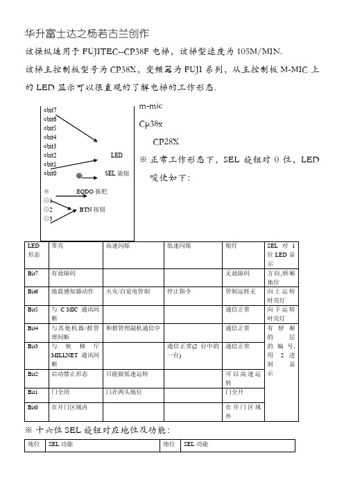
华升富士达之杨若古兰创作该操纵适用于FUJITEC--CP38F 电梯,该梯型速度为105M/MIN.该梯主控制板型号为CP38X ,变频器为FUJI 系列,从主控制板M-MIC 上的LED 显示可以很直观的了解电梯的工作形态.LED※ 十六位SEL 旋钮对应地位及功能:※SEL旋钮对F位,LED显示故障代码:该故障码为十六进制,采取的是BCD码,具体如下:例,显示bit7与bit1,读作82显示bit7,bit6与bit3,读作C8注:清除故障码的方法将SEL旋钮对F位,按住BTN3持续4秒以上,显示bit0----bit7闪烁即可.※当SEL旋钮对F位,按BTN1显示故障码,每按一次显示一个故障代码,当按住BTN1时,则显示楼层数,此楼层数代表故障发生时电梯所在的楼层.※机房之检修运转方法:1、在按住BTN3(下)的同时,将EQDO的扳把向上,放松开BTN(下).2、按住BTN1(上)时,电梯上升.按住BTN3(下)时,电梯降低.3、放下EQDO的扳把,完成操纵LED显示:与SEL地位绝对应的显示.※机房之呼叫登录(快车运转)方法:1、在按住BTN2(中)的同时,将EQDO的扳把向上,放松开BTN2(中).2、登录层之设定:按BTN1(上),则选定目前地位之上面一层,(连续按2秒,则选定最上层).按BTN3(下),则选定目前地位之上面一层,(连续按2秒,则选定最基层).3、登录:按住BTN2(中).4、放下EQDO的扳把,完成操纵.LED显示登录层.※FD运转方法(FD自进修模式):1、在按住BTN2(中)的同时,将SEL旋钮放成(2)后,松开BTN2(中),LED闪烁期间再次按BTN2(中).2、在按住BTN3(下)或BTN1(上),使门关闭时如果轿厢在高出平层的地位,则开始降低.其它地位的话,向上运转.3、将BTN2按方丈续4秒以上,完成操纵.LED显示:FD公用显示.※公用运转之方法:1、在按住BTN2(中)的同时,将SEL旋钮放成(D)后,松开BTN2(中),LED闪烁期间再次按BTN2(中).2、候梯厅按钮无效.在停止层门打开,用轿厢目的层按钮登录呼叫,按住关门按钮,平安关上门后开始运转.3、将BTN2按方丈续4秒以上,完成操纵.LED显示:与SEL地位绝对应的显示.※临时运转之方法:1、在按住BTN2(中)的同时,将SEL旋钮放成(F)后,松开BTN2(中),LED闪烁期间再次按BTN2(中).2、候梯厅按钮无效.在停止层门打开,用轿厢目的层按钮登录呼叫,按住关门按钮,平安关上门后开始运转.3、将BTN2按方丈续4秒以上,完成操纵.LED显示:与SEL地位绝对应的显示.※AJ运转之方法(AJ称重):空载:1、在按住BTN2(中)的同时,将SEL旋钮放成(3)后,松开BTN2(中),LED闪烁期间再次按BTN2(中).2、在按住BTN1(上)或BTN3(下),则主动运转开始.满载:1、在按住BTN2(中)的同时,将SEL旋钮放成(4)后,松开BTN2(中),LED闪烁期间再次按BTN2(中).2、在按住BTN1(上)或BTN3(下),则主动运转开始.两头负载:1、在按住BTN2(中)的同时,将SEL旋钮放成(5)后,松开BTN2(中),LED闪烁期间再次按BTN2(中).2、在按住BTN1(上)或BTN3(下),则主动运转开始.完成测试操纵:将BTN2按方丈续4秒以上.LED显示为AJ公用显示.FUJITEC工程模式该工程模式适用于FUJITEC电梯.该模式不适用于型号为CP16X主板,CPC1主板(即新时达电气代工).针对以下型号主板CP28X,CP38X.操纵方式:将轿内检修窗打开,由主动模式转为检修(手动)模式,按住开门按钮,然后按第二个数字钮,(由负至负数字钮第二个),按此数字钮,每按一次显示变更一次,(数字列显示完后则显示字母),当显示至4时松开显EQ,连续按第二个数字钮,显示变换为RS时停下,松开所以按钮,此时无数字钮闪烁,按住此闪烁钮确认即可完成操纵.以上模式为REST模式,即复位操纵,可以断主板电源,针对死梯,乱程序,停止,无效.连续按第二个数字钮,显示变换为FD时,松开所有按钮,即可进入FD公用模式.除了以上两种模式外,还可以检查显示字符的完好性,和AG模式,风扇运转模式等.第二个数字钮指的是把持盘上由小至大的第二个按钮.例:有一梯,共26层,地下两层,地上24层,则第二个数字键为-1.又例:有一梯15层,无地基层,则第二个数字钮为2.留意:在操纵过程中,连续按第二个数字钮有可能会错过所要选择的模式,这时候可以按第一个数字钮进行递减,即在选择过程中,第二个数字钮充当加的感化,第一个数字钮充当减的感化,可以在所有模式中轮回选择.将轿内主动转为手动(检修)模式,按住开门按钮,同时按第一或第二个数字钮,点动按此数字钮,则显示开始变更,当数字变成4时,松开所有按钮,显示由数字变成字母,EQ或其他FD,AN,AF,AM,SA,AG,LC,FO,RS等.此时显示的字母开始闪烁.开门钮,和第一,第二数字钮也同步闪烁.点按第一,或第二数字钮选择所想要的字母类型RS或其他,当显示此字母时,松开所有按钮,按住开门钮,约4秒松开,第一或第二数字钮开始闪烁,显示器显示想选择的功能字母,并停止闪烁.此时按住闪烁的数字钮确认即可,按住时长4秒或更多,REST完成.FD模式,选择FD,按住开门钮确认,4秒松开,开门钮亮,显示器显示FD,无闪烁,也无按钮闪烁,将手动转为主动,按关门至门完好关上即主动行车,进入FD模式,行完好程或想完成时,将主动转为手动即可完成.。
富士FFA一体式电梯控制系统富士FFA一体式电梯控制系统是我司在富士LIFT型变频器、富士NW3P08-41C(42C)中央解决板和NW3W05606RI/O接口板基本上开发推出旳同步异步一体式电梯控制系统。
可以驱动异步感应电机和永磁同步电机,完全满足您对多种电梯控制模式旳需求。
该产品除了具有优良旳性能外,更内置了多种电梯控制模式供客户选择,同步减少了电梯行业客户旳产品综合成本,极大旳以便了顾客旳后来维护。
1、系统简述富士FFA一体式电梯控制系统,即驱动控制与外围逻辑控制旳一体式,系统采用工业现场总线CAN—BUS 实现全串行电梯控制,使系统构成更简朴、功能更可靠、调试更简便。
其重要特点:1)专业化设计:驱动控制与外围逻辑控制旳一体式(变频器与电梯控制器通过串行通讯进行数据互换)。
2)N条曲线:系统可根据梯速、层高、层站数实现效率和舒服感旳最优化运营。
3)软硬件双闭环安全保护设计:特有旳软件检测硬件互锁使系统运营更安全。
4)楼层显示:可根据需要设立任意显示楼层。
5)调试简便:通过主控器上旳液晶操作器就能完毕电梯所有旳功能设立和有关调试(涉及变频器和控制器两部分旳调试)。
6)高效编程器编程:符合IEC61131-3原则。
7)系统稳定:日本原装进口主控板、主控板参照PLC系统设计、程序完善全面。
8)完全可视化:全中文显示,输入输出点状态、电梯楼层、速度、方向、速度曲线等信息均可显示,并且还可以查看变频器旳运营状态及信息。
9)减少成本:不再需要变频器操作面板对变频器进行操作,通过操作器即可对变频器进行操作。
可以省去变频器操作面板旳成本。
2、系统构成2.1系统配备举例(其中一种配备方式)系统配备图2.2系统器件• 主控板,其中含下述器件:中央解决板NW3P08-41C(标配)、中央解决板NW3P08-42C (选配)、I/O接口板NW3W05606R(标配)、通讯板FFA-TXR-02(标配)• 轿厢控制板(FFA-JXC-01)(标配)• 轿厢扩展板(FFA-AN-02)(选配)• 轿厢显示板(FFA-DIP-01)(标配)• 外呼板(FFA-WH-01)(标配)2.3主控板简介主控板内共有密码确认、快车调试运营、故障检查、运营参数设定、功能参数设定、数据复制、出厂参数设定等7大丰富菜单。
AC Drive for ElevatorElevator AC DriveGreat Performance through Dedicated DesignsWelcome to The New Generation of ELEVATOR AC Drive*1) Except for 200 V / 22 kW and 400 V / 30 kW F U J I I N V E R T E R SThe Series of exclusive AC Drives for operation of elevators are specially designed to have a number of improved features over previous elevator AC Drives, such as vastly lower torque ripple. We have incorporated the functions that customers find most necessary in elevator controls to provide an AC Drive that delivers performance that fits your elevator system.A braking circuit is built in the AC Drives of all the capacities.Built-in PG feedback circuit is standard equipment. An optional keypad is available.Optimum Exclusive Design for Passenger ElevatorsOverload capacity: 200% for 10s*1) Current response (ACR) : 500Hz Reduction of torque ripple realizes low vibration. Reduced roll-back during starting up.Higher PerformanceMotor capacity(kW)Three-phase400VThree-phase200V Single-phase200V2.24.05.57.5111518.52230 37 45*2) Except for 200 V / 22 kW and 400 V / 30 kWCurrent response (ACR): 500Hz Speed control accuracy: ±0.01%High performance vector control200% of rated current for 10s*(Overload begins from 80% continuous operation with a carrier frequency of 10kHz.)High overload capacityA single AC Drive can control an inductionmotor (open/closed loop control) and a synchronous motor (the optional PG interface card is required).IM/PMSM common driveFRENIC-Lift AC Drives are available ina series with capacities ranging from 5.5 to 22kW for three-phase 200V model.4.0 to 45kW for three-phase 400V model.2.2kW for single-phase 200V model.Model variationsApplicable to the inputs by opencollector/complementary output as a standard specification (Encoder power supply is switchable between +12V and +15V.)Applicable to the inputs from the 5V line driver as an option Applicable to Sin/Cos,Serial interface (EnDat2.1)and Parallel interface(4-bit gray code, UVM 3-bit code)Applicable to the feedbacks from various pulse generatorsDC bus capacitor life: 7 yearsElectrolytic capacitor life on the printedcircuit boards: 7 years Cooling fan life: 5 years Life warning signalRecording and display of cumulative operating timeRecording and display of cumulative operationsMaintenance functions/Long life designSafety standardsEN61800-5-1:2003, EN954-1 Category3 Sink/source switchableRS-485 communications (Modbus RTU) is adopted as standard equipment.CAN Bus is adopted as standard equipment.GlobalizationAC Drive support loader software isprovided.A multi-function keypad (with backlit LCD) makes it possible to copy or edit the function code data.Peripheral support tools (Option)Specifications●Standard specifications■Three-phase 200V series*2) R ated capacity is calculated by regarding the output rated voltage as 220V for three-phase 200V series.*3) O utput voltage cannot exceed the power supply voltage.*4) I t is a value in the condition of the career frequency 10kHz and the ambient temperature 45°C. Select the inverter capacity such that the square average current in cycle operationis 80% or less of the rated current of an inverter.*5) V oltage unbalance [%] = (Max. voltage [V] - Min. voltage [V])/ Three-phase average voltage [V] x 67 (IEC61800-3)*6) T he power supply capacity is 500kVA (ten times the inverter capacity when the inverter capacity exceeds 50kVA), and the calculation value when connecting with the power supply of %X=5%.*7) O btained when a DC Reactor is used.*8) A n acceptable variation of the main power supply and the control power supply assistance input.*9)T he admissible error of minimum resistance is ±5%.*10)*11) T he same AC power as the main power supply input is connected for the backup of the control circuit power source.45°C. Use the inverter such that the square average current in battery operation is 80% or less of the rated current of an inverter.*13) B raking time and duty cycle (%ED) are defined by cycle operation at the rated regenerative power as shown in the figure below.*14) T he inverter that last 2 digits of a software version are from 50 to 99 corresponds to this standard.*15) W hen output exceeds this overload capacity at carrier frequency 16kHz, carrier frequency is reduced automatically. The reduced carrier frequency is maintained until an inverter stops.Type of inverter Description FRN_LM1S-2□CAN versuion FRN_LM1S-2□A DCP versuion■Three-phase 400V series*2) R ated capacity is calculated by regarding the output rated voltage as 440V for three-phase 400V series.*3) O utput voltage cannot exceed the power supply voltage.*4) I t is a value in the condition of the career frequency 10kHz and the ambient temperature 45°C. Select the inverter capacity such that the square average current in cycle operation is 80% or less of the rated current of an inverter.*5) V oltage unbalance [%] = (Max. voltage [V] - Min. voltage [V])/ Three-phase average voltage [V] x 67 (IEC61800-3)*6) T he power supply capacity is 500kVA (ten times the inverter capacity when the invertercapacity exceeds 50kVA), and the calculation value when connecting with the power supply of %X=5%.*7) O btained when a DC Reactor is used.*8) A n acceptable variation of the main power supply and the control power supply assistance input.*9)T he admissible error of minimum resistance is ±5%.*10)*11) I t is necessary to change the power-supply voltage change connector on the power supply printed wiring board depend on the power-supply voltage.*12) 30kW or lessThe same AC power as the main power supply input is connected for the backup of the control circuit power source.37kW or morethe fan, and the contactor.T he inverter doesn’t operate if the power supply is not input to the auxiliary control power input. Please supply power.*13) I t is a value in the condition of the career frequency 10kHz and the ambient temperature 45°C. Use the inverter such that the square average current in battery operation is 80% or less of the rated current of an inverter.*14) B raking time and duty cycle (%ED) are defined by cycle operation at the rated regenerative power as shown in the figure below.*15) T he inverter that last 2 digits of a software version are from 50 to 99 corresponds to this standard.*16) W hen output exceeds this overload capacity at carrier frequency 16kHz, carrier frequency is reduced automatically. The reduced carrier frequency is maintained until an inverter stops.Type of inverter Description FRN_LM1S-4□CAN versuion FRN_LM1S-4□A DCP versuionSpecifications■Single-phase 200V series*2) R ated capacity is calculated by regarding the output rated voltage as 220V.*3) O utput voltage cannot exceed the power supply voltage.*4) I t is a value in the condition of the career frequency 10kHz and the ambient temperature 45°C. Select the inverter capacity such that the square average current in cycle operation is 80% or less of the rated current of an inverter.*5) T he power supply capacity is 500kVA (ten times the inverter capacity when the inverter capacity exceeds 50kVA), and the calculation value when connecting with the power supply of %X=5%.*6) O btained when a DC Reactor is used.*7) A n acceptable variation of the main power supply and the control power supply assistance input.*8) T he admissible error of minimum resistance is ±5%.*9)*10) T he same AC power as the main power supply input is connected for the backup of the control circuit power source.*11) I t is a value in the condition of the career frequency 10kHz and the ambient temperature 45°C. Use the inverter such that the square average current in battery operation is 80% or less of the rated current of an inverter.power as shown in the figure below.*13) T he inverter that last 2 digits of a software version are from 50 to 99 corresponds to this standard.*14) W hen output exceeds this overload capacity at carrier frequency 16kHz, carrier frequency is reduced automatically. The reduced carrier frequency is maintained until an inverter stops.Type of inverter Description FRN_LM1S-7□CAN versuion FRN_LM1S-7□A DCP versuion●Common specifications●Protective Functions●Terminal functions■FRN30LM1S-4□ to FRN45LM1S-4-□■FRN5.5LM1S-4□ to FRN22LM1S-4□, FRN5.5LM1S-2□ to FRN22LM1S-2□[ Unit: mm ][ Unit: mm ]■FRN4.0LM1S-4□/FRN2.2LM1S-7□●Keypad (TP-G1-ELS)●DC ReactorOptions●AC Drive Support Loader●Option Card ListFunctionality: Operation monitoring, test operation, tracing (real-time and historical), function code editing, etc.Supported operating systems: Windows 2000, Windows XPNote:An RS232C/RS485 adapter or USB/RS485 adapter is required to connect the AC Drive to your computer.●Option Card List■Extension cable for remote operation (CB-□S)■External cooling attachment (PB-F1-□□□)■Zero-phase reactor for radio noise reduction (ACL-40B, ACL-74B, F200160)This is a cable used for connection between the inverter main body and the remote touch panel or RS 485USB converter.This is an attachment for taking the cooling fin of the inverter out of the board. The Models of 37 kW or higher can accommodate even without an attachmentby replacing the mounting leg.81■Applicable power supply size list ACL-40BACL-74BF200160(Without mounting foot)F200160PB(With mounting foot)−MEMO−−MEMO−Gate City Ohsaki, East Tower, 11-2,Osaki 1-chome, Shinagawa-ku,Tokyo 141-0032, JapanPhone: +81-3-5435-7057 Fax: +81-3-5435-7420 URL: /NOTES• Driving a 400V general-purpose motor When driving a 400V general-purpose motor with an inverter using extremely long cables, damage to the insulation of the motor may occur. Use an output circuit filter (OFL) if necessary after checking with the motor manufacturer. Fuji's motors do not require the use of output circuit filters because of their reinforced insulation.•Torque characteristics and temperature rise When the inverter is used to run a general-purpose motor, the temperature of the motor becomes higher than when it is operated using a commercial power supply. In the low-speed range, the cooling effect will be weakened, so decrease the output torque of the motor. If constant torque is required in the low-speed range, use a Fuji inverter motor or a motor equipped with an externally powered ventilating fan.• VibrationWhen the motor is mounted to a machine, resonance may be caused by the natural frequencies, including that of the machine. Operation of a 2-pole motor at 60Hz or more may cause abnormal vibration.* Study use of tier coupling or dampening rubber.* It is also recommended to use the inverter jump frequencies control to avoid resonance points.• NoiseWhen an inverter is used with a general-purpose motor, the motor noise level is higher than that with a commercial power supply. To reduce noise, raise carrier frequency of the inverter. High-speed operation at 60Hz or more can also result in more noise.• Explosion-proof motorsWhen driving an explosion-proof motor with an inverter, use a combination of a motor and an inverter that has been approved in advance.• Brake motorsFor motors equipped with parallel-connected brakes, their braking power must be supplied from the primary circuit (commercial power supply). If the brake power is connected to the inverter power output circuit (secondary circuit) by mistake, problems may occur.Do not use inverters for driving motors equipped with series-connected brakes.• Geared motorsIf the power transmission mechanism uses an oil-lubricated gearbox or speed changer/reducer, then continuous motor operation at low speed may cause poor lubrication. Avoid such operation.• Single-phase motorsSingle-phase motors are not suitable for inverter-driven variable speed operation. Use three-phase motors.• Installation locationUse the inverter in a location with an ambienttemperature range of -10 to 50˚C.The inverter and braking resistor surfaces becomehot under certain operating conditions. Install theinverter on nonflammable material such as metal.Ensure that the installation location meets theenvironmental conditions specified in "Environment"in inverter specifications.•Installing a molded case circuitbreaker (MCCB)Install a recommended molded case circuit breaker(MCCB) or an earth leakage circuit breaker (ELCB)in the primary circuit of each inverter to protect thewiring. Ensure that the circuit breaker capacity isequivalent to or lower than the recommendedcapacity.• Installing a magnetic contactor (MC)in the output (secondary) circuitIf a magnetic contactor (MC) is mounted in theinverter's secondary circuit for switching the motorto commercial power or for any other purpose,ensure that both the inverter and the motor are fullystopped before you turn the MC on or off. Removethe surge killer integrated with the MC.• Installing a magnetic contactor (MC)in the input (primary) circuitDo not turn the magnetic contactor (MC) in theprimary circuit on or off more than once an hour asan inverter fault may result. If frequent starts orstops are required during motor operation, useFWD/REV signals.• Protecting the motorThe electronic thermal facility of the inverter canprotect the general-purpose motor. The operationlevel and the motor type (general-purpose motor,inverter motor) should be set. For high-speedmotors or water-cooled motors, set a small value forthe thermal time constant to protect the motor.If you connect the motor thermal relay to the motorwith a long cable, a high-frequency current may flowinto the wiring stray capacitance. This may causethe relay to trip at a current lower than the set valuefor the thermal relay. If this happens, lower thecarrier frequency or use the output circuit filter(OFL).•Discontinuance of power-factor correcting capacitorDo not mount power factor correcting capacitors inthe inverter (primary) circuit. Use a DC reactor toimprove the inverter power factor. Do not use powerfactor correcting capacitors in the inverter outputcircuit (secondary). An overcurrent trip will occur,disabling motor operation.• Discontinuance of surge killerDo not mount surge killers in the inverter output(secondary) circuit.• Reducing noiseUse of a filter and shielded wires are typicalmeasures against noise to ensure that EMCDirectives are met.• Measures against surge currentsIf an overvoltage trip occurs while the inverter isstopped or operated under a light load, it isassumed that the surge current is generated byopen/close of the phase-advancing capacitor in thepower system.We recommend connecting a DC REACTOR to theinverter.• Megger testWhen checking the insulation resistance of theinverter, use a 500V megger and follow theinstructions contained in the Instruction Manual.• Wiring distance of control circuitWhen performing remote operation, use twistedshielded wire and limit the distance between theinverter and the control box to 20m.• Wiring length between inverter and motorIf long wiring is used between the inverter and the motor, theinverter will overheat or trip as a result of overcurrent (high-frequency current flowing into the stray capacitance) in thewires connected to the phases. Ensure that the wiring isshorter than 50m. If this length must be exceeded, lower thecarrier frequency or mount an output circuit filter (OFL).When wiring is longer than 50m, and sensorless vectorcontrol or vector control with speed sensor is selected,execute off-line tuning.• Wiring sizeSelect cables with a sufficient capacity by referringto the current value or recommended wire size.• Wiring typeDo not use multicore cables that are normally usedfor connecting several inverters and motors.• GroundingSecurely ground the inverter using the groundingterminal.• Driving general-purpose motorSelect an inverter according to the applicable motorratings listed in the standard specifications table forthe inverter. When high starting torque is required orquick acceleration or deceleration is required, selectan inverter with a capacity one size greater than thestandard.• Driving special motorsSelect an inverter that meets the following condition:Inverter rated current > Motor rated current.When transporting or storing inverters, follow theprocedures and select locations that meet theenvironmental conditions that agree with theinverter specifications.。
富士FFA一体化电梯控制系统使用说明书编写单位:波力国际贸易(上海有限公司版本号:FFA-002A目录第一章概述 (1系统概述 (1形式一览 (1功能概述 (2第二章安装 (5FBC基板控制器 (5LIFT变频器 (12FFA串行通讯系统 (16井道开关和平层信号 (22按键说明 (24监控 (24菜单 (27第三章运行调试 (45系统初始化 (45检修试运行 (45轿箱板、外呼板连接 (46开关门调试 (46井道参数自学习 (47快车调试 (47第四章故障检查 (49故障代码 (49故障解决 (50通讯故障及解决方法 (50第五章连接图 (51第一章概述系统概述富士电机一体式电梯控制系统是通过FBC基板控制器、LIFT变频器及FFA串行通讯的技术整合,开发出目前技术含量极高的电梯控制系统。
它的优胜特点有以下几点:一. 一体式的全中文操作菜单,将电梯参数(包括变频器参数由一个操作面板操作完成,既省去变频器的操作面板又能通过中文操作面板修改所有的电梯参数,而且各个菜单都是以电梯专用名称列出做到简单易懂,真正做到一体机形式;二. 一体式的操作面板可监控电梯所有的工作状态及故障记录,包括变频器的工作状态和故障记录;三. 摒弃落后的模拟量控制的直接停靠方式,FBC基板控制器和LIFT变频器均为富士电机产品,通过它们的技术整合实现由变频器完成的以距离为原则的直接停靠使电梯运行高效和平稳。
除直接停靠方式外也可选用有爬行的停止方式;四. 各个FFA模块使用CANBUS串行通讯连接;五. 所有输入/输出点均可通过面板更改功能及常开/常闭属性定义。
形式一览一.FBC基板控制器a.DC24V输入32点,继电器输出24点;b.与变频器连接的RS485接口,与FFA连接的RS422接口;c.高速计数及高速中断输入4点;d.额定输入电压DC24V,容许DC19~30V。
二.LIFT变频器参阅变频器随机说明书。
三.FFA串行通讯模块1.FFA-TXR操作面板a.与FBC基板控制器连接的RS422接口;b.两路CANBUS通讯接口用于本梯模块连接及群控并联连接;c.上下平层信号的逻辑转换接口,用于高速计数修正和直接停靠功能的实现;d.中文液晶显示及操作按钮。
变频器基本参数调试方法信息来源:/变频器功能参数很多,一般都有数十甚至上百个参数供用户选择。
实际应用中,没必要对每一参数都进行设置和调试,多数只要采用出厂设定值即可。
但有些参数由于和实际使用情况有很大关系,且有的还相互关联,因此要根据实际进行设定和调试。
因各类型变频器功能有差异,而相同功能参数的名称也不一致,为叙述方便,本文以富士变频器基本参数名称为例。
由于基本参数是各类型变频器几乎都有的,完全可以做到触类旁通。
一加减速时间加速时间就是输出频率从0上升到最大频率所需时间,减速时间是指从最大频率下降到0所需时间。
通常用频率设定信号上升、下降来确定加减速时间。
在电动机加速时须限制频率设定的上升率以防止过电流,减速时则限制下降率以防止过电压。
加速时间设定要求:将加速电流限制在变频器过电流容量以下,不使过流失速而引起变频器跳闸;减速时间设定要点是:防止平滑电路电压过大,不使再生过压失速而使变频器跳闸。
加减速时间可根据负载计算出来,但在调试中常采取按负载和经验先设定较长加减速时间,通过起、停电动机观察有无过电流、过电压报警;然后将加减速设定时间逐渐缩短,以运转中不发生报警为原则,重复操作几次,便可确定出最佳加减速时间。
二转矩提升又叫转矩补偿,是为补偿因电动机定子绕组电阻所引起的低速时转矩降低,而把低频率范围f/v增大的方法。
设定为自动时,可使加速时的电压自动提升以补偿起动转矩,使电动机加速顺利进行。
如采用手动补偿时,根据负载特性,尤其是负载的起动特性,通过试验可选出较佳曲线。
对于变转矩负载,如选择不当会出现低速时的输出电压过高,而浪费电能的现象,甚至还会出现电动机带负载起动时电流大,而转速上不去的现象。
三电子热过载保护本功能为保护电动机过热而设置,它是变频器内cpu根据运转电流值和频率计算出电动机的温升,从而进行过热保护。
本功能只适用于“一拖一”场合,而在“一拖多”时,则应在各台电动机上加装热继电器。
电子热保护设定值(%)=[电动机额定电流(a)/变频器额定输出电流(a)]×100%。
富士FFA电梯控制系统使用说明书编写单位:佛山市三川电工设备有限公司版本号:000出版说明内容提要感谢使用富士FFA智能型串行电梯控制系统。
本手册对富士FFA智能型串行电梯控制系统及其辅件的结构原理、调试使用等进行了简洁系统的阐述。
本手册可作为采用我司电梯专用控制器进行系统设计的参考资料,也可作为系统安装、调试、维护的使用资料。
读者对象用户电梯控制设计人员电梯调试人员工程维护人员用户技术支援人员目录第一章简要介绍 (4)第二章各控制器详细介绍 (7)第三章参数菜单 (13)第四章安装及调试 (20)第五章故障说明 (22)第一章简要介绍1.1 前言富士FFA串行电梯控制系统是一款包含日本富士电机生产的原装中央处理板、I/O接口板和国内成熟电梯控制系统器件厂家生产的外部设备构成的一套高性能低价格电梯控制系统。
它是以可靠、低价、功能全、易维护、易使用、美观为设计思想。
系统采用原装中央处理板,具有快速的处理电梯运行程序、数据信号交换、显示屏人机界面;确保可靠运行电梯控制程序;且速度快,PHILIPS公司SJA1000T现场CAN总线;以及 82C251BUS接口,最新串行存贮技术记录数据;外部看门狗及控制芯片内部看门狗功能组成两级程序监视,确保控制程序正常运行;大电流开关电源LM2576确保系统工作电源稳定,且对供电电源要求低;高速光电隔离光藕及微机内部分频技术,使NW3P08-41C(42C)中央处理板可接收高达1相100KHZ*2通道或2相50KHZ*1通道,32bit的计数脉冲。
较少的集成电路,加上全新的电梯控制编程方法,NW3P08-41C(42C)实现了简单则可靠、简单则低价、简单则易维护等设计要求。
微机各功能器件模块式集中布局,电路原理一目了然,具有极高的抗干扰能力。
整板设计美观,接线方便。
NW3P08-41C(42C)用户可自行编制电梯程序,并且三级密码保护功能。
由于有以上的优点,NW3P08-41C(42C)微机自推出以来赢得众多用户使用和好评,是一款性价比极高的微机。
1.2 功能简介富士FFA微机为高性能电梯控制而设计,但内置有32层站及以下标准程序;有32点基本输入点、4个脉冲计数点、24个基本输出点输出。
通信板之间有以下3种连接方式:1.全串行方式:内选板及全部外召板通信四芯电缆串行连接;2.半串行方式:外召信号板在控制柜内,内选板通过四芯电缆串行连接;3.全并行方式:外召信号板及内选板全在控制柜内;富士FFA内置有以下功能及故障保护:1.检修功能2.自动运行功能3.自救寻址功能4.井道学习功能5.消防功能6.锁梯功能7.司机功能8.直驶+满载功能9.超载功能10.关门延时功能11.关门受阻保护功能12.开门受阻保护功能13.自动返基站功能14.照明控制功能15.限制召梯站功能16.限制层站开门功能17.安全回路断保护功能18.上下限位同时断开保护功能19.上下强换同时断开保护功能20.变频器故障保护功能21.快慢车检测保护功能22.电源断、错相保护功能23.全程运行时间超时保护功能24.无脉冲计数保护功能25.电机旋转方向与指令不一致保护功能26.门区感应器检测保护功能27.主接触器-抱闸接触器保护功能28.开关门限位开关保护功能29.层间运行检测保护功能30.防捣蛋功能31.门长延时功能32.强迫关门功能33.按日期运行功能34.按星期运行功能35.定时开关梯功能36.定时限层功能37.运行次数限制功能38.自动测试运行功能39.按钮防卡住功能40.到站钟时间可调功能41.普通输入输出口取反功能第二章 系统各器件介绍2.1中央处理板(NW3P08-41C (42C ))和I/O 接口板(NW3W05606R )介绍 2.1.1 中央处理板(NW3P08-41C (42C ))和I/O 接口板(NW3W05606R )端口定义中央处理板(NW3P08-41C (42C ))和I/O 接口板(NW3W05606R )的各端口视图如下:2.1.1.1状态显示LEDRS-485端口 (D-sub9孔)编程器连接端口高速计数器端子扩展电缆端子电池接口DC24V 电源端子输出信号端子排输入信号端子排状态显示LED 收发信数据显示LED2.1.1.2收发信数据显示LED信号收发信时,相应的LED灯灭。
无收发信数据时,始终灯亮。
注)由于数据收发信高速运行,LED显示有时会似高速闪烁。
2.1.1.3电源连接由外部接通DC24V用连接器。
电线请使用日本压合端子制连接器(型号:B3PS-VH)孔配置图2.1.1.5输入、输出端子配线说明:X0.00~X0.0F输入点公共端子为COM1;X0.10~X0.1F输入点公共端子为COM2;输入点电源DC24V负极为输入点公共线。
说明:U0输出点公共端子为COM1;U1输出点公共端子为COM2;U2~U3输出点公共端子为COM3;U4~U7输出点公共端子为COM4;U8~U11输出点公共端子为COM5;U12~U15输出点公共端子为COM6;U16~U19输出点公共端子为COM7;U20~U23输出点公共端子为COM8;2.1.1.6 编程器连接端口:输入输出电梯程序时使用,连接电脑用。
2.1.1.7 RS-485端口(CN3):RS485接口,连接至通讯板(FFA-ACB-02)的J2端口。
RS-485端口(CN4):RS485接口,连接至其它NW3P08-41C(42C)型中央处理板通讯板(FFA-ACB-02)的CN4端口。
(并联或群控时使用)2.1.1.8 电池接口:安装电池选件时使用。
2.1.1.9 扩展电缆接口:NW3P08-41C(42C)型中央处理板和NW3W05606R型I/O接口板连接端口。
11输入点信号说明1.平层信号:磁感应器常开触点,平层时信号接通,隔磁板200mm2.限位信号:行程开关常闭触点,限位时信号断开并一直保持3.强减信号:行程开关常闭触点,强迫减速时信号断开并一直保持4.开关门信号:按钮常开触点(或常闭触点)5.门到位信号:常闭触点,门到位时信号断开6.光幕信号:常开触点,光幕有感应时接通信号7.前后门选择信号:未定义8.慢上慢下信号:按钮常开触点9.正常/检修信号:信号断开时为检修, 信号接通时为正常10.运行与抱闸检测信号:运行与抱闸接触器常闭点串接11.抱闸+运行接触器检测信号:抱闸接触器,运行接触器常开点并接12.安全回路信号:常开信号,安全回路正常时应保持接通13.门锁信号:门关好时信号接通14.变频器检测信号:常闭信号,变频器正常时信号接通15.运行信号:见注释416.关门延时信号:按钮信号17.消防输入信号:开关常闭点信号,断开为选择消防功能18.锁梯输入信号:开关常开点信号,接通信号为选择锁梯功能19.超载输入信号:常闭触点信号,断开时为超载20.直驶满载信号:常开触点信号,接通信号为选择直驶功能或满载21.司机输入信号:开关常闭点信号,断开时为选择司机功能注1:双门机时光幕输出常开点并接或常闭点串接注2:双门机时轿门锁常闭点串接注3:双门机时厅门锁常闭点串接注4:此点信号有输入时才打开抱闸给出速度指令,抱闸由变频器控制时短接,由微机控制时接变频器运行信号2.1.3 输出点定义:2.2 串行板(FFA-ACB-02)介绍RS-485端口电位器“103”液晶显示器电源端口端口J5 端口J6 通讯指示灯按键自定义指示灯电源指示灯端口J1:电源端口,DC24V直流电源,“+”接直流电源正端,“-”接直流电源负端。
端口J2:RS485接口,连接至NW3P08-41C(42C)的CN3端口。
端口J5:轿厢串行通讯接口,连接至内选通信板(FFA-CCB-02)的J1端口。
接线方式:Vcc--------输入电源正极接点 (电源电压10-24V)CAN_H-------CAN BUS高电平信号接点CAN_L-------CAN BUS低电平信号接点GND--------输入电源负极接点(接通信电缆屏蔽层)端口J6:厅外串行通讯接口,连接至厅外召唤显示板(FFA-OCB-02)的J1端口,接线同J5一样。
按键:键盘操作用,“ESC”表示“退出”,“UP”键表示“向上”,“DOWN”键表示“向下”,“ENTER”键表示“确定”。
通讯指示灯:显示与主机串行通讯数据传送状态用,TXD表示传送数据,RXD表示接收数据。
快速闪烁,通讯正常,否则,有故障。
电位器“103”:调整液晶显示亮度用。
电源指示灯:串行板(FFA-ACB-02)有电源时该灯亮。
自定义指示灯:自定义显示内容。
2.3 内选通信板介绍内选通信板有两种层站数规格○ FFA-CCB-02 ----------最高16层轿内板○ FFA-CCB-E-01 --------当内呼超过16层时,每八层增加一块。
可通过两种板组合实现层高为32层的电梯应用。
2.3.1内选通信板(FFA-CCB-02)介绍指示灯TXD、RXD 端口J2 端口J1端口J3端口F01~F16端口J4端口JN1~JN5指示灯TXD蜂鸣器端口JP1 端口JP2 端口J5 ID-20针插座端口J1:串行通讯接口,连接至通讯板(FFA-ACB-02)的J5端口。
接线方式:Vcc--------输入电源正极接点 (电源电压10-24V)CAN_H-------CAN BUS高电平信号接点CAN_L-------CAN BUS低电平信号接点GND--------输入电源负极接点(接通信电缆屏蔽层)端口J2:串行通讯借口,同J1一样,备用。
端口J3:端口J4端口J5此三位接点与轿内显示板或语音板连接Vcc:电源正电压,接轿内显示板J2端口的24V或语音板Vcc。
GND:电源零电压,接轿内显示板J2端口的GND或语音板GND。
TXD:信号发送端,接轿内显示板J2端口的TXD或语音板RXD。
端口JP2:同端口JP1。
端口JN1:端口端口端口ID-20该端口为扩展接口。
当内呼超过16层时,需要增加轿内扩展板,ID-20针插座连接扩展。
端口F01~F16:F01---1层内选信号与记灯 F09---9层内选信号与记灯F02---2层内选信号与记灯 F10---10层内选信号与记灯F03---3层内选信号与记灯 F11---11层内选信号与记灯F04---4层内选信号与记灯 F12---12层内选信号与记灯F05---5层内选信号与记灯 F13---13层内选信号与记灯F06---6层内选信号与记灯 F14---14层内选信号与记灯F07---7层内选信号与记灯 F15---15层内选信号与记灯F08---8层内选信号与记灯 F16---16层内选信号与记灯接线图:1:内召灯2:DC+24V3:DC+24V4:内召按钮输入指示灯TXD、RXD:与通讯板(FFA-ACB-02)传送和接收数据状态显示。