LAPAR 电动阀门说明书
- 格式:pdf
- 大小:2.56 MB
- 文档页数:12

电动阀门智能定位器使用说明书Intelligent Electric Valve Locator Instruction Manual一、简介Introduction二、面板说明Panel Description1、按键功能说明The Key Function Description(1) A/M 键:A/M KeyA.手 /自动模式切换;Manual/Auto mode switchingB.手动模式下按 2 秒进入标定模式、In Manual mode, press it for 2 seconds to enter calibration modeC.标定模式下标定结果的储存和确认等;In calibration mode the verification and storage of the calibration results and soon(2)▲键:▲KeyB.手动模式下控制电机正转;In Manual mode control the motor forwardB.标定模式下做累加键使用;In calibration mode as the use of cumulative( 3)▼键:▼KeyA. 手动模式下控制电机反转;In Manual mode control the motor reversalB.标定模式下做递减键使用;In calibration mode as the use of decreaseC.自动模式下按 2 秒进入初始化模式In Auto mode, press it for 2 seconds to enter the initialization mode2、数码管显示说明(参照表1)LED display description (Table 1)( 1)手动模式下,显示阀门相应开度,显示范围不受0.00~ 100.0 的限制;In Manual mode, display the corresponding valve opening, the display range is notlimited from 0.00 to100.0( 2)自动模式下,正常状态显示目前阀门开度,显示范围不受0.00~ 100.0 的限制;In Auto mode, display the current valve opening, the display range is not limitedfrom 0.00 to100.0( 3)标定模式下,各显示详细含义见标定功能说明;In calibration mode the specific meaning refer to the function description.3、状态 LED 显示说明Status LED display description( 1)OPEN:电动履行器控制输出电路“开”输出有效;Electric actuator control output circuit “opening ”output is effective ( 2)SHUT :电动履行器控制输出电路“闭”输出有效;Electric actuator control output circuit “ closing output” is effective ( 3)MANU :定位器处于手动模式;Locator is in manual mode( 4)AUTO :定位器处于自动模式;Locator is in Auto mode4、用户标定LED 显示说明User calibration LED display description( 1)DRTA :正相标定,即4mA 对应阀门全闭,20mA 对应阀门全开;Normal phase calibration, 4mA corresponds to the valve fully closed,20mAcorresponds to the valve fully open( 2)RVSA :反相标定,即4mA 对应阀门全开,20mA 对应阀门全闭;RP Calibration, 4mA corresponds to the valve fully closed, 20mA corresponds tothe valve fully open( 3)OPEN:无输入信号时,阀门自动调至全开;No input signal, the valve automatically transferred to full open ( 4)STOP:无输入信号时,阀门自动停在目前地点;No input signal, the valve automatically stops at the current location ( 5)SHUT :无输入信号时,阀门自动调至全闭;No input signal, the valve automatically transferred to full closed.三、性能参数 ( Performance parameters)1、控制精度: 0.1% ~ 1.0% (可设置)Control precision: 0.1% ~ 1.0% (can be set)2、工作功耗: <10WWorking Power3、工作电压:沟通100~ 240VOperating Voltage: AC 100 ~ 240V4、电动履行器反应电位器:500 欧姆~ 10K 欧姆Electric actuator feedback potentiometer5、输入信号: 4~ 20mAInput signal6、输入阻抗: 250 欧姆Input impedance7、输出信号: 4~ 20mAOutput signal8、输出信号负载:≤450 欧姆Output Load9、环境温度: -20 ° C~ 70 ° CThe ambient temperature10、环境湿度:≤80% RHThe ambient humidity四、接线说明 ( wiring instructions)五、标定操作 ( calibration operation)在手动状态下,按住A/M 键 5 秒进入参数标定状态按A/M 键按▼键显示 F1-2 显示 F.1.-.2.按 A/M 键按 A/M 键最后确认相位按▼键显示 F2A1 自动标定按 A/M 键按A/M 键按▼键显示 F2H1 最小转角标定按 A/M 键按 A/M 键按▼键显示 F2H2 最大转角标定按 A/M 键按 A/M 键按▼键显示 F3-2 显示 F.3.-.2.按 A/M 键按 A/M 键最后确认模式按▼键显示 --05 显示 -.-.0.5.按 A/M 键按 A/M 键最后确认精度退出标定状态,答复到正常运转状态按▼键选择相位模式按A/M 键显示 F2A1按A/M显示 F2A1按A/M显示 F2A1按▼键无信号模式按A/M 键按▼键改变精度按A/M 键In manual mode, hold down the A / M button for 5 seconds to enter calibration statusPress A / Mpress ▼press ▼Display F1-2Display F.1.-.2. Select Phase Mode Press A/M keyFinal phase confirmationPress A/MPress A/Mpress ▼Display Press A/MDisplay Press A/MF2A1F2H1Automatic calibrationDisplay F2A1Press A/Mpress ▼Press A/MMinimum angle calibration Display F2A1Press A/MPress ▼Press A/MDisplay F2H2Minimum angle calibration Display F2A1Press A/MPress A/Mpress ▼press ▼Display F3-2Display F.3.-.2.No signal mode Press A/MPress A/MPress A/MFinal confirmation modePress ▼Press ▼Display --05Display -.-.0.5.Change the precisionPress A/MFinal accuracy confirmationPress A/MPress A/MOut of calibration status, return to normal operating state1、标定模式进入:手动模式下,按A/M 键并保持 2 秒,将进入标定模式;Enter the calibration mode: in manual mode, press A / M key and keep 2 seconds, will enterthe calibration mode2、相位标定:Phase calibration:(1)显示目前实质相位设置,如是正相模式则显示“F1- 2”,反相模式则显示“ F1- 1”,相应标定 LED 也会被点亮。

CE1N4893en 2020-05-11Building Technologies4893SSA.. without auxiliary switch SSA..1 with auxiliary switchACVATIX™Electromotoric actuatorsFor radiator valves, MiniCombiValves (MCV) and small valvesSSA31..SSA81..SSA61..·SSA31.. operating voltage AC 230 V 3-position control signal ·SSA81.. operating voltage AC 24 V 3-position control signal ·SSA61.. operating voltage AC / DC 24 V DC 0…10 V control signal ·SSA61EP.. equal-percentage valve characteristic ·Nominal force 100 N·Automatic identification of valve stroke·Direct mounting with coupling nut, no tools required·Basic types complete with plug-in connecting cable, length 1.5 m ·Optional cable types·Cable length 2.5 m and 4.5 m ·Halogen-free cables·Manual override and position indication·Parallel connection of multiple actuators possible·Auxiliary switch integrated in SSA31.1 and SSA81.1 actuators ·Optional tamper-proof fitting to prevent dismantlingUse·For radiator valves, VDN.., VEN.., VUN.., Combi valves VPP46.., VPI46.. and MiniCombiValves, VPD.., VPE..·For small valves, VD1..CLC· For radiator valves with M30 x 1.5 threaded fitting, nominal closing dimension11.6 mm and a 2.5 mm nominal stroke (without adapter). Also for use with third-party valves in conjunction with AV-type adapter2/10SiemensCE1N4893enSmart InfrastructureBuilding Technologies2020-05-11· For modulating or 3-position control in heating systems, chilled ceilings and terminal units.Type summaryTypereference Operating voltage Run time at 50 HzControl signalConnecting cableAuxiliary switchSSA31AC 230 V150 s3-position1.5 m SSA31/001)no cable SSA31.1 1.5 m YesSSA81AC 24 V1.5 m SSA81/001)no cable SSA81.1 1.5 m YesSSA61AC / DC 24 V 34 s DC 0...10 V1.5 m SSA61/001)no cable SSA61EP 2) 1.5 m SSA61EP/002)no cable1)For available cable lengths or terminal block connectors refer to "Accessories", page 42)With equal-percentage valve characteristicTypereference DescriptionOperating voltage Control signalASY3L25Connecting cable 2.5 mAC 230 V3-positionASY3L45Connecting cable 4.5 m ASY8L25Connecting cable 2.5 m AC 24 V ASY8L45Connecting cable 4.5 mASY8L45HF Connecting cable 4.5 m, halogen-free, VDE 0207-24ASY6L25Connecting cable 2.5 m AC / DC 24 V DC 0...10 V ASY6L45Connecting cable 4.5 m ASY6L45HF Connecting cable 4.5 m, halogen-free, VDE 0207-24ASY98Retaining screw for terminal block connectors. Included in ASY99 and ASY100.ASY99Terminal block connector for 3-position actuators SSA81../00ASY100Terminal block connector for DC 0…10 V modulating actuators SSA61/00AL40Tamper-proof fitting to prevent dismantling of actuators Adapter typefor third-party valves Adapter type for third-party valves AV51Beulco old (M30x1.0)AV56Giacomini AV522)Comap AV57Herz AV53Danfoss RA-N (RA2000)AV58Oventrop old (M30x1.0), till 2002AV54Danfoss RAVL AV592)Vaillant AV55Danfoss RAV AV60TA, till 20021)AV61Markaryd (MMA)1) No adapter required for type TBV-C 2)While stocks lastOrdering Type Stock no.DescriptionQuantity SSA81/00SSA81/00Electromotoric actuator 2ASY8L45ASY8L45Connecting cable2Actuators, valves and accessories are packed separately. Items are suppliedindividually packed.Overview tables, see page 9.AccessoriesExample:DeliveryRev.-No.3/10SiemensCE1N4893en Smart Infrastructure2020-05-11Equipment combinationsk vs = nominal flow rate of cold water (5...30 °C) through the fully open valve (H 100)at a differential pressure of 100 kPa (1 bar)V & = Nominal volume flow at 0.5 mm strokeTo ensure trouble-free operation of third-party valves with the SSA.. actuator, the valves must satisfy the following requirements:·Threaded connections with coupling nut M30 x 1.5·Nominal force F £ 100 N ·Dimension x x > 9.0 mm ·Dimension y y £ 14.5 mmFunction / mechanical designWhen the actuator is driven by DC 0…10 V control voltage or by a 3-position signal, it produces a stroke which is transmitted to the valve stem.The description of operation in this document applies to the valve versions which are fully open when de-energized (NO).·Voltage at Y1:Stem retracts Valve opens ·Voltage at Y2:Stem extends Valve closes ·No voltage at Y1 and Y2:Actuator maintains its current position· The valve opens / closes in proportion to the control signal at Y.· At DC 0 V, the valve is fully closed (A à AB).· When power supply is removed, the actuator maintains its current position.1)Actuator is calibrated to 2.5 mm stroke of VPI46.15.L06S t r o k e 2,5 m m ((c a l i b r a t e d )1)22.51.510.500246810control signal Y [V]Type reference Valve type k vs [m 3/h]V&[l/h]PN class Data sheet VDN.., VEN.., VUN..Radiator valves 0.09…1.41PN 10N2105, N2106VPD.., VPE..MCV radiator valves 25…483N2185VD1..CLC Small valves 0.25…2.60N2103VPP46.., bi valves 30…4001PN 25N4855For other radiator valves with type AV.. adapters refer to "Type summary / accessories"Radiator valves (M30 x 1.5) from other manufacturers, without adapter:· Heimeier · Crane D981..· TA-Type TBV-C · Oventrop M30 x 1.5 (from 2001)· MNG · Junkers · Honeywell-Braukmann · Cazzaniga · Beulco (new)Valves from othermanufacturers3-position control signalSSA31.. / SSA81..DC 0...10 V control signalSSA61, SSA61/004/10SiemensCE1N4893enSmart InfrastructureBuilding Technologies2020-05-11Combi valves VPI46../VPP46.. in combination with SSA61EP.. have an equal-percentage characteristics.· The valve opens / closes in equal percentage ratio to the control signal at Y.· At DC 0 V, the valve is fully closed (A à AB).· When power supply is removed, the actuator maintains its current position.1)Actuator is calibrated to 2.5 mm stroke of VPI46.15L06S t r o k e 2,5 m m (c a l i b r a t e d )1)2.42.51.510.500246810control signal Y [V]·Plastic housing·Locking-proof, maintenance-free gear train·Manual override with hexagonal socket wrench 3 mm ·Reduced power consumption in the holding positions·Load-dependent switch-off in the event of overload and in stroke end positions·Parallel operation of 6 SSA31.., 24 SSA81.. and 10 SSA61..possible, provided the controllers’ output is sufficient ·Terminal block connectors for customer made cables available (only for use with AC 24 V and AC / DC 24 V actuators)·Connecting cables with AC 24 V and AC 230 V connectors cannot be mixed up·Halogen-free cables availableAccessoriesAdapter types AV51 to AV61 are available for mounting the SSA.. actuators on third-party radiator valves as shown under "Type summary/accessories", page 2.1xtighten gentlyType ASY98 to secure the cable connector. Included in ASY99 and ASY100.The cable connector snaps into position,but can be additionally secured with the retaining screw.DC 0...10 V control signal SSA61EP,SSA61EP/00Features and advantagesAdapter type AV.. for third-party valves Tamper-proof fitting AL40Retaining screw ASY985/10SiemensCE1N4893en Smart Infrastructure2020-05-11For special cable lengths of the AC / DC 24 V actuators.·Type ASY99 for 3-position actuators SSA81../00·Type ASY100 for DC 0…10 V modulating actuators SSA61/00The terminal block connectors are supplied complete with mounting instructions (74 319 0385 0).Notes The actuators must be electrically connected in accordance with local regulations (refer to "Connection diagrams", page 9).Regulations and requirements to ensure the safety of people and property must be observed at all times!The permissible temperatures (refer to "Technical data", page 7) must be observed.The connecting cable of the actuator may come into contact with the hot valve body,provided the temperature of the valve body does not exceed 80 °C.Actuator types SSA 31.1 and SSA81.1 have a built-in auxiliary switch. The switch cannot be fitted in other actuators later.Mounting instructions (Ref. 74 319 0497 0) are enclosed in the product packaging.The actuator and valve are assembled with the coupling nut; no tools or adjustments are required.The actuator must be fitted in position 1 with the power disconnected (refer also to "Manual override", page 6):·Position the actuator and tighten the coupling nut manually ·Do not use any tools such as wrenches·Avoid lateral pressure or (cable) tension on the mounted actuator!In the case of actuators without a connecting cable (SSA../00), the separately orderedCrimp ferrule on stripped wire of connecting cable.When commissioning, check the wiring and the functioning of the actuator and auxiliary switch, if fitted.·Actuator stem extends (from position 1 to 0): Valve closes ·Actuator stem retracts (from position 0 to 1): Valve opens During commissioning and whenever the operating voltage is switched on,the SSA61.. runs a self-calibration routine. (Valve stroke 0® Max.stroke ® Setpoint).Never intervene manually in this process.ON0 %EngineeringMountingOrientationInstallationCommissioningTerminal block connectors ASY99ASY1006/10SiemensCE1N4893enSmart InfrastructureBuilding Technologies2020-05-11The second or third attempt at calibration occurs automatically after an 8-minute delay.After three failed calibration attempts the actuator stem remains in the extended position and the radiator valves are closed.For valves with strokes < 1.5 mm, the actuator/valve combination locks after three failed calibration attempts.The new Siemens type VDN.., VEN.. and VUN.. radiator valves have in all 1.5 mm stroke.A 3 mm hexagonal socket wrench can be used to move the actuator to any position.However, if a control signal from the controller is present, then this takes priority in determining the position.To retain the manually set position, unplug the connecting cable or switch off the operating voltage and the control signal.2.5 mm stroke5.5 mm strokeThe actuators are maintenance-free.When carrying out service work on the plant, following must be noted:·Turn power off (e.g. remove the plug)·If necessary, disconnect electrical connections from the terminals·The actuator must be commissioned only with a correctly mounted valve in place!SSA.. actuators cannot be repaired; the complete unit must be replaced.DisposalWarrantyThe technical data given for these applications is valid only when the actuators are used with the Siemens valves listed under "Equipment combinations", page 2.The use of the SSA.. actuators in conjunction with third-party valves invalidates any warranty offered by Siemens Building Technologies / HVAC Products.Note: Correctcalibration is only possible ·with valve·stroke > 1.5 mmOperationNoteManual overrideMaintenance!Repair7/10SiemensCE1N4893en Smart Infrastructure2020-05-11Technical dataPower supplyControlFunctional dataElectrical connectionsNorms and directivesDimensions /weight Housing colors 1)Provided the controller output is sufficient2)The documents can be downloaded from /bt/download8/10SiemensCE1N4893enSmart InfrastructureBuilding Technologies2020-05-11General ambient conditionsOperation EN 60721-3-3Transport EN 60721-3-2Storage EN 60721-3-1Environmental conditions Class 3K3Class 2K3Class 1K3Temperature +1...+50 °C –25...+70 °C –5...+50 °C Humidity 5...85 % r.h.< 95 % r.h. 5...95 % r.h.Connecting cableConnection terminalsY2Y1G4864Z 15Control signal CLOSE Control signal OPENSystem potential AC 24 VG0Y G4864Z 16System neutralControl signal DC 0...10 V System potential AC/DC 24 VFactory setting: 50 %0...50 % Q11® Q1250...100 % Q11® Q14The switching point can be adjusted by turning the switching cam with a screwdriver (see Mounting Instructions).Recommended connecting cable: H03VV-F, 2x0.5…0.75 mm 2.ASY3L.. with SSA31..ASY8L.. with SSA81..ASY6L.. with SSA61..ASY99for SSA81..ASY100for SSA61..Terminals for auxiliary switchesSSA31.1, SSA81.19/10SiemensCE1N4893en Smart Infrastructure2020-05-11Connection diagramsN Controller Y ActuatorL System potential AC 230 V NSystem neutralY1, Y2Control signal OPEN, CLOSE Q1, Q2Controller contactsN Controller YActuatorSP, G System potential AC 24 V SN, G0System neutralY1, Y2Control signal OPEN, CLOSE Q1, Q2 Controller contactsN Controller YActuatorSP, G System potential AC 24 V SN, G0System neutral Y Control signalSSA31..SSA81..SSA61..10/10SiemensCE1N4893enSmart InfrastructureBuilding Technologies2020-05-11DimensionsDimensions in mm8377484893M 0172.59M30 x 1,54893M 0298.5834889.5M30 x 1,59Revision numbersType reference Valid from Rev.-No.Type reference Valid from Rev.-No.SSA31K SSA61K SSA31/00K SSA61/00KSSA31.1K SSA81K SSA81/00K SSA81.1KActuator without auxiliary switch SSA31..SSA81..SSA61..Actuator with auxiliary switch SSA31.1..SSA81.1..Issued bySiemens Switzerland LtdBuilding Technologies Division International Headquarters Theilerstrasse 1a 6301 Zug SwitzerlandTel. +41 41-724 24 24/buildingtechnologies © Siemens Switzerland Ltd, 2005Technical specifications and availability subject to change without notice.。
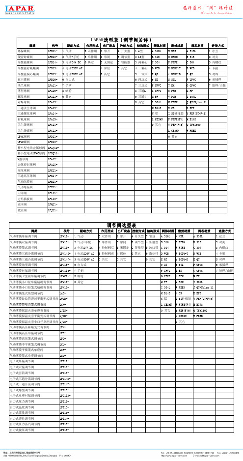
阀类代号驱动方式作用形式出厂状态控制方式结构形式阀体材质密封材质阀芯材质连接方式环保蝶阀LPB11- 1 气动 D 双作用 1 常开 A 开关型 1 A型 A 316L N NBR A 316L 1 法兰硬密封蝶阀LPB12- 2 气动+手轮S 单作用 2 常闭 B 调节型 2 LT型 B 316O EPDM B 316 2 对夹高性能蝶阀LPB14- 3 电动24V DC0 其它 3 无固定 C 智能型 3 两偏心 C 304P PTFE C 304 3 内螺纹高性能衬氟蝶阀LPB15- 4 电动220V AC 4 保位0 其它 4 三偏心 D WCB R BODY-T D WCB 4 卡箍高性能偏心蝶阀LPB13- 5 电动380V AC0 其它 5 一体式 E QT r BODY-D E QT 5 对焊真空蝶阀LPB16- 6 自力式 6 两块式 e HT S STL F UPVC 6 承插焊法兰球阀LPA11-7 手柄7 三块式 F UPVC T EK G CPVC7 胶焊/由任薄型球阀LPA16-8 蜗轮8 三通L G CPVC U FPM H PP螺纹球阀LPA12-0 其它9 三通T H PP V POM I 304L对焊球阀LPA15-0 其它I 304L W PEEK J QT+Nylon 11三通法兰球阀LPA13-M B148X CR K EPT三通螺纹球阀LPA14-N 铝Z SI硅橡胶Y FEP(QT+F46)衬氟球阀LPA19-L CE3MN P PTFE(F4)M B148卫生级球阀LPC11-0 其它Y FEP(F46)Q TFM1600卫生级蝶阀LPC12-L CE3MN W PEEKUPVC球阀LPD11-0 其它UPVC蝶阀LPD12-精小型电动金属球阀LPAJ12-精小型电动UPVC球阀LPDJ11-V型球阀LPA17-金属密封球阀LPA18-高压球阀LPK11-三通高压球阀LPK14-气动隔膜阀LPE11-气动角座阀LPF11-刀闸阀LPL11-方形插板阀LPL12-止回阀LPQ11-截止阀LPJ11-LAPAR选型表(调节阀另详)阀类代号驱动方式作用形式出厂状态控制方式结构形式阀体材质密封材质阀芯材质连接方式气动薄膜单座调节阀LPH11- 1 气动 D 双作用 1 常开 A 开关型7 常规 A 316L N NBR A 316L 1 法兰气动薄膜双座调节阀LPH12- 2 气动+手轮S 单作用 2 常闭 B 调节型 4 低温型 B 316O EPDM B 316 2 对夹气动薄膜笼式调节阀LPH13- 3 电动24V DC A 控制阀后 3 无固定 C 智能型 5 波纹管 C 304P PTFE C 304 3 内螺纹气动薄膜三通分流调节阀LPH148- 4 电动220V AC B 控制阀前 4 保位0 其它 6 散热性 D WCB R BODY-T D WCB 4 卡箍气动薄膜三通合流调节阀LPH147- 5 电动380V AC0 其它0 其它0 其它 E QT r BODY-D E QT 5 对焊气动薄膜角型调节阀LPH15- 6 自力式 e HT S STL F UPVC 6 承插焊气动薄膜衬氟调节阀LPH113-7 手柄 F UPVC T EK G CPVC7 胶焊/由任气动薄膜卫生级单座调节阀LPHC11-8 蜗轮G CPVC U FPM H PP气动薄膜小口径单座精确调节阀LPH11-0 其它H PP V POM I 304L气动薄膜小口径笼式精确调节阀LPH13-I 304L W PEEK J QT+Nylon 11气动薄膜笼式角型调节阀LAC-M B148X CR K EPT气动薄膜波纹管密封平衡笼式调节阀LWCB-N 铝Z SI硅橡胶Y FEP(QT+F46)L CE3MN P PTFE(F4)M B148调节阀选型表气动薄膜降噪音笼式调节阀LCN-气动薄膜保温夹套单座调节阀LJTS-0 其它Y FEP(F46)Q TFM1600气动薄膜保温夹套平衡笼式调节阀LJCB-L CE3MN W PEEK气动薄膜保温夹套小口径单座调节阀LJLS-0 其它气动薄膜高压降噪笼式调节阀LPN-气动薄膜高压单座调节阀LPS-气动薄膜高压笼式调节阀LPC-气动薄膜不平衡笼式调节阀LCU-气动薄膜平衡笼式单座阀LCP-气动薄膜笼式单座调节阀LSC-电子式单座调节阀LPG11-电子式双座调节阀LPG12-电子式套筒调节阀LPG13-电子式三通分流调节阀LPG148-电子式三通合流调节阀LPG147-电子式角型调节阀LPG15-电子式单座衬氟调节阀LPG113-自力式压力调节阀LPI11-自力式温度调节阀LPI12-自力式流量调节阀LPI13-自力式液位调节阀LPI14-自力式压力蒸汽调节阀LPI15-自力式微压调节阀LPI16-。

电动蝶阀使用说明书概要电动蝶阀是由角行程电动执行器和蝶形阀体组成的控制阀。
主要适用于空调、制冷、采暖等楼宇自动控制系统,同时也适用于化工、石油、冶金、电力、轻工等行业的生产过程的自动控制系统。
以满足调节流量和截流介质的要求。
主要特点:²外形美观、结构紧凑, 小型轻便,安装方便.易于拆装及维修。
² 90 度回转启闭迅速,调节性能好。
²启闭力矩较小,转轴两侧蝶板受介质作用基本相等,而产生转矩的方向相反,故启闭较省力。
²低压密封性能好。
²流体阻力小。
²功能强劲,有多种控制信号与反馈信号供选择。
²蜗轮输出轴一体化设计,传动精度高。
²安全可靠,能够通过AC1500V 耐压检测,选用F 级绝缘电机。
²启动和关闭次数2 万次。
² IP68 高标准防护等级。
执行器规格阀体规格外形尺寸DN50~DN500安装注意事项1. 属非防爆产品,所以不要安装在有爆炸性气体的室内。
2. 请预留进线、手动时所需要的空间。
3. 室外安装注意事项4. 调节阀与管道的连接:阀体与安装管道保持自然同轴,避免阀体侧漏。
注:阳光直射会造成机内高温,加速元器件的老化。
雨水会加速密封件的老化,造成渗水而损坏机器。
配线连接1 配线电缆要求:1.1 DN50-DN80 的执行器请用φ4-φ8 的电缆线。
1.2 DN100-DN125 的执行器请用φ8-φ10 的电缆线。
1.3 DN150-DN450 的执行器请用φ8-φ12 的电缆线。
1.4 根据进线线锁的尺寸,请使用合适的电缆线,以确保连线的安全可靠。
1.5 将电缆线穿过电缆夹头,将线头按线路图固定在端子台上。
1.6 旋紧线锁的外套,以锁紧电缆线。
注:原则上已将所需电缆引出阀外1米,电缆线的六根线颜色与电动执行器内部颜色相符,用户只需使用合适的电缆线将其连接并做好防水处理即可。
2 配线线管要求:2.1 使用电线管时,必须采取有效的防水措施。

Sinclair Collins ®•2 vias o 3 vias•Válvula Operada por Diafragma •Normalmente Cerrada •Normalmente Abierta •1/4" a 2" Roscada (NPT/G)•1/2" a 1 1/2" Bridada (ANSI 300#)•Control de ProcesoParker Hannifin Ind. e Com. Ltda.Av. Lucas Nogueira Garcez 218112325-900 Jacareí - Brasil Boletín de VentasBrazil Automation DivisionVálvula Roscada - Asiento SuaveCodificaciónOpciónRosca "G" - Agregar el sufijo "BSP" después del código.1/4"3,353,75--C264-000911/4"3,353,75--C284-000713/8"3,053,45--C284-000813/8"3,053,25--C264-001011/4"--4,154,25C264-001113/8"--4,904,25C264-001211/4"3,353,754,154,25C264-001313/8"3,053,454,904,25C264-001411/4"3,353,754,154,25C264-001513/8"3,053,254,904,25C264-001611/2"6,607,30--C264-200111/2"6,607,30--C274-200113/4"8,307,80--C274-200213/4"8,307,80--C264-200211/2"--8,008,00C264-200313/4"--9,9010,80C264-200411/2"6,607,308,008,00C264-200513/4"8,307,809,9010,80C264-200611/2"6,607,308,008,00C264-200713/4"8,307,809,9010,80C264-200811"15,2016,00--C264-400111"15,2016,00--C274-400111 1/4"19,2020,80--C274-400211 1/4"19,2020,80--C264-400211"--19,8023,80C264-400311 1/4"--24,2027,50C264-400411"15,2016,0019,8023,80C264-400511 1/4"19,2020,8024,2027,50C264-400611"15,2016,0019,8023,80C264-400711 1/4"19,2020,8024,2027,50C264-400812"37,5040,00--C274-600511 1/4"30,2028,80--C274-600111 1/2"34,2035,00--C274-600211 1/4"30,2028,80--C264-600111 1/2"34,2035,00--C264-600212"37,5040,00--C264-601711 1/4"--38,5043,00C264-600311 1/2"--38,5044,00C264-600412"--45,5054,50C264-601811 1/4"30,2028,8038,5043,00C264-600511 1/2"34,2035,0038,5044,00C264-600612"37,5040,0045,5054,50C264-601911 1/4"30,2028,8038,5043,00C264-600711 1/2"34,2035,0038,5044,00C264-600812"37,5040,0045,5054,50C264-60201ØConexión CódigoFunciónPresión TrabajoPilotoTemperatura28 bar2,4a 2,8 bar-40°a +204°C2 NA(Conexión en Línea )2 NC (Conexión en Línea )2 NA(Conexión en Ángulo )3 NC 3 NA Cuerpo Básico Cv1-22-12-33-21/4"28 bar2,4a 2,8 bar -40°a +204°C2 NA(Conexión en Línea )2 NC(Conexión en Línea )2 NA(Conexión en Ángulo )3 NC 3 NA 1/2"28 bar2,4a 2,8 bar -40°a +204°C2 NA (Conexión en Línea )2 NC(Conexión en Línea )2 NA(Conexión en Ángulo )3 NC 3 NA 1"28 bar2,4a 2,8 bar -40°a +204°C2 NA (Conexión en Línea )2 NC (Conexión en Línea )2 NA(Conexión en Ángulo )3 NC3 NA1 1/2"OpciónRosca "G" - Agregar el sufijo "BSP" después del código.ØConexión CódigoPresión TrabajoPilotoTemperatura Cuerpo Básico Cv1-22-12-33-21/4"26 bar 34 bar 26 bar 26 bar34 bar 34 bar1/2"34 bar1"31 bar1 1/2"34 bar31 bar31 bar34 bar1/4"2,062,06--C264-00091/4"1,801,85--C284-00073/8"1,952,25--C284-00083/8"2,572,48--C264-00101/4"--2,443,30C264-00113/8"--2,352,62C264-00121/4"2,062,062,443,30C264-00133/8"2,572,482,353,62C264-00141/4"2,062,062,443,30C264-00153/8"2,572,482,353,62C264-00161/2"6,206,30--C264-20011/2"6,106,50--C274-20013/4"7,608,00--C274-20023/4"7,606,80--C264-20021/2"--7,408,80C264-20033/4"--9,6012,00C264-20041/2"6,206,307,408,80C264-20053/4"7,606,809,6012,00C264-20061/2"6,206,307,408,80C264-20073/4"7,606,809,6012,00C264-20081"13,5013,80--C264-40011"13,2012,60--C274-40011 1/4"17,9017,00--C274-40021 1/4"17,2016,50--C264-40021"--17,9018,40C264-40031 1/4"--24,8026,00C264-40041"13,5013,8017,9018,40C264-40051 1/4"17,2017,0024,8026,00C264-40061"13,5013,8017,9018,40C264-40071 1/4"17,2017,0024,8026,00C264-40082"36,0034,70--C274-60051 1/4"31,9029,70--C274-60011 1/2"35,0032,90--C274-60021 1/4"31,9029,70--C264-60011 1/2"35,0032,90--C264-60022"36,0034,70--C264-60171 1/4"--43,2048,50C264-60031 1/2"--45,0049,90C264-60042"--47,3052,00C264-60181 1/4"31,9027,4043,2048,50C264-60051 1/2"35,0031,3045,0049,90C264-60062"36,0034,7047,3052,00C264-60191 1/4"31,9027,4043,2048,50C264-60071 1/2"35,0031,3045,0049,90C264-60082"36,0034,7047,3052,00C264-60202,1a 2,8 bar-40°a +232°C2,1a 2,8 bar -40°a +232°C2,1a 2,8 bar -40°a +232°C2,1a 2,8 bar-40°a +232°CFunción2 NA (Conexión en Línea )2 NC(Conexión en Línea )2 NA(Conexión en Ángulo )3 NC 3 NA 2 NA(Conexión en Línea )2 NC(Conexión en Línea )2 NA(Conexión en Ángulo )3 NC 3 NA 2 NA(Conexión en Línea )2 NC(Conexión en Línea )2 NA(Conexión en Ángulo )3 NC 3 NA 2 NA(Conexión en Línea )2 NC(Conexión en Línea )2 NA(Conexión en Ángulo )3 NC3 NAØConexión CódigoPresión TrabajoPilotoTemperaturaCuerpo Básico Cv1-22-12-33-2FunciónVálvula Bridada - Asiento Duro31 bar 1/2"6,607,30--C264-20011F 1/2"6,607,30--C274-20011F 3/4"8,307,80--C274-20021F 3/4"8,307,80--C264-20021F 1/2"6,607,308,008,00C264-20051F 3/4"8,307,809,9010,80C264-20061F 1/2"6,607,308,008,00C264-20071F 3/4"8,307,809,9010,80C264-20081F 2 NC(Conexión en Línea )1/2"1"15,2016,00--C264-40011F 1"15,2016,00--C274-40011F 1 1/4"19,2020,80--C274-40021F 1 1/4"19,2020,80--C264-40021F 1"15,2016,0019,8023,80C264-40051F 1 1/4"19,2020,8024,2027,50C264-40061F 1"15,2016,0019,8023,80C264-40071F 1 1/4"19,2020,8024,2027,50C264-40081F 1"1 1/2"34,2035,0038,5044,00C264-60061F 1 1/2"34,2035,00--C274-60021F 1 1/2"34,2035,00--C264-60021F 1 1/2"34,2035,0038,5044,00C264-60081F1 1/2"-40°a +204°C-40°a +204°C-40°a +204°C2,4a 2,8 bar 2,4a 2,8 bar2,4a 2,8 bar28 bar28 bar28 bar2 NA(Conexión en Línea )3 NC 3 NA 2 NA(Conexión en Línea )2 NC((Conexión en Línea )3 NC 3 NA2 NA (Conexión en Línea )2 NC (Conexión en Línea )3 NC 3 NAØConexión CódigoPresión TrabajoPilotoTemperaturaCuerpo Básico Cv1-22-12-33-2Función1/2"6,206,30--C264-2001F 1/2"6,106,50--C274-2001F 3/4"7,608,00--C274-2002F 3/4"7,606,80--C264-2002F 1/2"6,206,307,408,80C264-2005F 3/4"7,606,809,6012,00C264-2006F 1/2"6,206,307,408,80C264-2007F 3/4"7,606,809,6012,00C264-2008F 2 NC(Conexión en Línea )1/2"1"13,5013,80--C264-4001F 1"13,2012,60--C274-4001F 1 1/4"17,9017,00--C274-4002F 1 1/4"17,2016,50--C264-4002F 1"13,5013,8017,9018,40C264-4005F 1 1/4"17,2017,0024,8026,00C264-4006F 1"13,5013,8017,9018,40C264-4007F 1 1/4"17,2017,0024,8026,00C264-4008F 1"1 1/2"35,0031,3045,0049,90C264-6006F 1 1/2"35,0032,90--C274-6002F 1 1/2"35,0032,90--C264-6002F 1 1/2"35,0031,3045,0049,90C264-6008F1 1/2"-40°a +204°C-40°a +204°C-40°a +204°C2,4a 2,8 bar2,4a 2,8 bar2,4a 2,8 bar34 bar34 bar34 bar2 NA(Conexión en Línea )3 NC 3 NA 2 NA(Conexión en Línea )2 NC(Conexión en Línea )3 NC 3 NA2 NA (Conexión en Línea )2 NC (Conexión en Línea )3 NC 3 NAVálvula Roscada Cuerpo Básico 1/2"1/4" -NPTA 3 RoscasBCCBBCFD E1231233/4"A B CDEFDimensiones (mm )Rosca (NPT )1/2"Modelo 1/2"3/4"213,6267,549,398,6184,2178,62-vias NAconexión en línea1/8" - NPTA 3 RoscasCBD E123FRosca (NPT )AB C D E F 1/4" o 3/8"169,2127,038,176,2109,5Dimensiones (mm )2-vias NAconexión en ángulo2-vias NC 3-vias NA 3-vias NCVálvula Roscada Cuerpo Básico 1 1/2"1/4" -NPTABC FD1231231/4" -NPTA 3 RoscasBCBCFD E123123A BC D E FDimensiones (mm)Rosca (NPT)1 1/4"2-vias NA conexión en ángulo 3-vias NA 3-vias NC2-vias NC conexión en líneaModelo1 1/2"363,52"467,01 1/4"1 1/2"3192"467,0457,582,6165,1298,4457,52-vias NAconexión en líneaEA BCDEFDimensiones (mm )Rosca (NPT )1"Modelo1 1/4"1"1 1/4"289356,668,3136,6241,32542-vias NA conexión en ángulo2-vias NC 3-vias NA 3-vias NC2-vias NAconexión en línea3 RoscasVálvula Bridada Cuerpo Básico 1/2" - Conexión de 1/2"Válvula Bridada Cuerpo Básico 1/2" - Conexión de 3/4"Válvula Bridada Cuerpo Básico 1" - Conexión de 1"Válvula Bridada Cuerpo Básico 1" - Conexión de 1 1/4"Parker Hannifin Ind. e Com. Ltda.Av. Lucas Nogueira Garcez 2181Esperança Caixa Postal 14812325-900 Jacareí, SPVálvula Bridada Cuerpo Básico 1 1/2" - Conexión de 1 1/2"。

Quarter Master Chief Series 92 ActuatorInstallation, Operationand Maintenance ManualTable of ContentsSeries 92 Electric Actuator Introduction (3)Description (3)Electrical Requirement (3)Installation (4)Electrical (4)Type 21 Ball Valve (4)Type 23 Ball Valve (3-way) (5)Type 57 / 57L Butterfly Valves (5)Actuator Mounting Dimensions (6)Operation (7)Manual Override Operation (7)Setting Limit Switches (7)Options (8)Single Limit Switch (8)Double Limit Switch (8)Heater and Thermostat (8)Mechanical Brake (9)Feedback Potentiometer (9)Series 92 Options Codes for Serial # Tags (10)Troubleshooting (10)Maintenance (12)ATEX Requirements (12)Spare Parts (13)Series 92 Electric Actuator IntroductionDescriptionThe Series 92 electric actuators feature a reversing,capacitor run motor, with a permanently lubricated gear train, and hardened steel spur gears. These actuators are equipped with integral thermal overload protection (AC models) with automatic reset, independently adjustable limit switches, declutchable manual override, beacon position indication, baked powder epoxy coating with stainless steel trim, ISO bolt circle, and 2 (two) ½” NPT conduit entries.Standard models are offered in 115 VAC, feature a combination enclosure of Nema-4X, 7 & 9, and, provide up to 2000 in-lbs. of output torque.Various options are available such as operating voltages, additional limit switches, heater and thermostat, feedback potentiometers, etc.Please see page 8 regarding these options.Electrical RequirementWARNING: Do not open actuator cover while circuits are energized.CAUTION: Proper voltage must be supplied to actuator or damage will result.CAUTION: If 115vac & 220vac models are PLC driven, output contacts of PLC should be rated at a minimum of 1.5 times required input voltage of actuatorNOTE: To conform to various electrical codes, a green grounding screw has been provided (on the baseplate) inside of actuator.Terminal Strip Wiring: 75° C Copper Supply Wires up to #14 AWG, wired as per the attached diagrams or the wiring diagram affixed inside of actuator cover. Control Wiring shall be insulated with conductors rated 105° C, 300 V minimum.Torque Terminal Strip Wiring to 5 in-lbs.115 Vac 230 Vac 12 Vdc 24 Vdc 12 Vac 24 Vac Cycle Timeper 90 Model Torque Amp Duty Amp Duty Amp Duty Amp Duty Amp Duty Amp DutyDegrees (in/lbs) Draw Cycle Draw Cycle Draw Cycle Draw Cycle Draw Cycle Draw Cycle (seconds) S92 400 0.5 100% 0.4 100% 2.075% 4.075% 2.075% 3.0 75% 10A92 700 0.8 75% 0.6 75% 2.075% 4.075% 2.075% 3.0 75% 10B92 1100 0.5 100% 0.4 100% 2.075% 4.075% 2.075% 3.0 75% 25C92 2000 1.0 50% 0.6 50% 2.075% 4.075% 2.075% 3.0 75% 25 NOTE: Amp rating is considered locked rotor.Duty cycles are for ambient temperature (73°F)InstallationElectricalReference Drawing #289S92Models S-92, A92, & B921A. To gain access to terminal strip (Part #24) it is necessary to remove manual override knob (Part #18) by loosening slotted setscrew (Part #39). Remove 2 cover screws and cover; the remaining 6 cover screws are packaged inside the actuator. Torque cover/base screws to 120 in-lbs.Note: Failure to properly tighten cover/base flange fasteners to 120 in/lbs may compromise the certified safety factors of the actuator.Model C921B. To gain access to terminal strip it is necessary to remove manual override hand wheel (Part #18A) by loosening slotted setscrew (Part #39). Remove cam (Part #51) by loosening 2 set screws (Part #52). Remove 2 cover screws and cover; the remaining 6 cover screws are packaged inside the actuator.Torque cover/base screws to 120 in-lbs.All Models2. Make electrical connections to terminal strip as shown on wiring schematiclocated inside the cover (per various electrical codes there is a green screw on the actuator base plate for grounding purposes). Terminals are suitable for up to #14 AWG wire. All units are completely calibrated prior to shipment, and no internal adjustments should be required.3. For United States units, Install 1/2" NPT conduit fitting(s) to actuator base.For ATEX Certified European Union units, Install M20 x 1.5 conduit fitting(s) to actuator base.Note: Proper conduit fitting must be used to maintain enclosure rating and not compromise the certified safety factors of the actuator(weatherproof, explosion proof or combination weather proof/explosion proof). NOTE: We recommend sealing conduit openings on units installed outdoors or exposed to large temperature swings (15ºF or more).We also recommend the Heater and Thermostat option in these applications. 4. Replace actuator (gasket if removed) cover, and install 8 cap screws suppliedand tighten securely to 120 in/lbs. For outdoor or wet locations it isrecommended prior to replacing the cover that the top shaft seal be cleaned and coated with silicone grease. Also clean shaft and lightly coat seal area of shaft with silicone grease. Unit is now ready for operation.Type 21 Ball ValvePosition the valve and the actuator to corresponding positions (either OPEN or CLOSED). The flats on the actuator shaft extension indicate valve positionType 21 Ball Valves (See Drawing #0107BV sizes ½” – 2”)Install mounting bracket #3 to actuator #2 using bolts #8 and washers #9. Insert coupling #4 on stem of valve #1 and then bolt valve #1 to mounting bracket #3 using bolts #5, nuts #7, and washers #6.Note: All bolts should be snug and not excessively over tightened.Type 21 Ball Valves (See Drawing #0113BV sizes 2-1/2” - 4")Install mounting bracket #3 to actuator #2 using bolts #8 and washers #9. Insert coupling #4 on stem of valve #1 and then bolt valve #1 to mounting bracket #3 using bolts #5, nuts #7, and washers #6.Note: All bolts should be snug and not excessively over tightened.Type 23 Ball Valve (3-way)Position the valve and the actuator to corresponding positions (either OPEN or CLOSED). The flats on the actuator shaft extension indicate valve positionType 23 Ball Valves (3-way): (See Drawing #0130BV, sizes ½” - 4”)Install mounting bracket #3 to actuator #2 using bolts #8 and washers#9. Insert coupling #4 on stem of valve #1 and then bolt valve #1 tomounting bracket #3 using bolts #5, nuts #7, and washers #6.Type 57 / 57L Butterfly ValvesCAUTION: If valve is in line, system must be shut down and have no line pressure before removing throttle plate and retaining washer.Position the valve and the actuator to corresponding positions (either OPEN or CLOSED). The flats on the actuator shaft extension indicate valve position Butterfly Valves (See Drawing # 0200BF57 sizes 1-1/2” - 6”)No specially machined stem or valve body drilling required. Remove handle (remove handle cap and hex head bolt) to expose throttle plate screws. Remove throttle plate and retaining washer to expose existing bolt pattern.Mount bracket #3 to actuator #2 with bolts #8 and washers #9 and tighten evenly. Insert coupling #4 into actuator #2.Install valve #1 onto mounting bracket #3 and align stem of valve to engage with coupling. (Line scribed on top of stem indicates disc orientation). Install bolts #5, washers #6 and nuts #7 and tighten evenly. Flats on actuator shaft indicate valve position. (Disc Orientation)Butterfly Valves (See Drawing #0168BF57 8” size)No specially machined stem or valve body drilling required. Remove gear operator by removing 4 thru bolts in body of valve to gear operator and lift off. Mount bracket #2 to actuator #10 using bolts #7 and washers #8. Insert actuator shaft adapter #9 into actuator #10. Install valve #1 to mounting bracket #2 and align stem of valve to engage with coupling. (Line scribed on top of stem indicates disc orientation). Install bolts #3, washers #4 & #5 and nuts #6 and tighten evenly. Flats on actuator shaft indicate valve position. (Disc Orientation) CAUTION: If mounted unit is installed other than straight up, the actuator should be supported independently to prevent side loading and loosening up ofOperationManual Override OperationReference Drawing #289S92Models S-92, A92, & B92Pull up the declutching knob (Part #18) and apply a 5/8" open end wrench to exposed flats and rotate within labeled limits as indicated by arrows.To re-engage simply rotate actuator shaft in the opposite direction until declutching knob drops back down into position.Model C92Push down on hand wheel (Part #18A) and rotate within labeled limits.To re-engage simply rotate actuator hand wheel until it moves up and re-engages.CAUTION: The manual override should only be used when there is no power applied to actuator. When power is restored the actuator will automatically resume normal operation.Setting Limit SwitchesReference Drawing #289S92Open Travel Limit Switch (Top Switch Part #25):Using declutchable manual override, move the valve into a full open position. Then loosen set screws on top cam (Part #40) and rotate cam (CCW) into limit switch arm until a click is heard, this designates the switch circuit has opened and defines a full open position. Tighten 2 set screws (Part #40) on cam.Close Travel Limit Switch (Bottom Switch Part #25):Using declutchable manual override, move the valve to a full closed position, loosen set screws on bottom cam (Part #40) and rotate cam (CW) into limit switch arm until a click is heard, this designates the switch circuit has opened and defines a full closed position. Tighten 2 set screws (Part #40) on cam.Manually position valve to midstroke. Reapply power to actuator and drive to open or closed position. Actuator motor will run. The shaft will not turn until drivepins (Part #7) reseat in drive gear. This could take up to 25 seconds.OptionsModels S92, A92, B92, C92Single Limit SwitchInstall additional limit switch on posts on opposite side of standard limit switches using screws provided.Wiring for switch is as follows:Pink = Common to Terminal #6Purple = NC to Terminal #7Blue = NO to Terminal #8Cam must be set so that this switch is tripped just ahead of Closed limit switch. Wire tie loose wiring and check operation before installing cover.Double Limit SwitchInstallation and wiring is the same as for the single limit switch, with the additionof wiring of the second switch as follows:Brown = Common to Terminal #9Green = NC to Ternimal #10Orange = NO to Terminal #11Cam must be set so that this switch is tripped just ahead of Open limit switch. Wire tie loose wiring and check operation before installing cover.Heater and ThermostatModels S92 & A92Install Heater into threaded hole located between actuator base gasket andmotor module.Wiring is as follows:Heater lead = Terminal #12Thermostat lead = Terminal #13Wire tie loose wiring and check operation before installing cover.Models B92 & C92Install Heater into threaded hole located between actuator shaft and motor module.Wiring is as follows:Heater lead = Terminal #12Thermostat lead = Terminal #13Wire tie loose wiring and check operation before installing cover.Mechanical BrakeLoosen two (2) motor screws diagonally from each other and install bracket with tabs facing upward. Tighten screwsInstall hexagonal adapter over armature shaft and tighten set screws.NOTE: The adapter should be resting on the step of the armature shaft.Install brake assembly onto hexagonal adapter making sure that the brake assembly is sitting flush on the bracket. Tighten with supplied screws.Remove motor leads “A” & “B” from capacitor and install “piggy back connectors to capacitor, the re-install motor leads to their original locations.Connect brake leads to piggy back connectors on capacitor (orientation does not matter)Wire tie loose wiring and check operation before installing cover.Feedback PotentiometerUsing 4-40 x 3/8 hardware, install potentiometer and bracket on standoffs by limit switches, with potentiometer gear facing output shaft.Install drive gear face down over output shaft.Wiring for potentiometer as follows:#1 on potentiometer (black) #14 on terminal strip.#2 on potentiometer (white) #15 on terminal strip.#3 on potentiometer (red) #16 on terminal strip.Using multimeter set at 2k ohms, calibrate potentiometer with leads from meter connected to terminals #15 and #16. With actuator in closed position multimeter should read between 95 and 100 ohms.Rotate actuator 90 degrees (open position).Connect leads from multimeter to terminal #14 and #15; multimeter should read 95 to 100 ohms.If necessary adjust open limit switch cam so that multimeter will read 95-100 ohms.Series 92 Options Codes for Serial # TagsExample 1: S92HTP XWJHeater & thermostat and feedback potentiometer installed.Example 2: A92BRM1XWJMechanical brake and 1 extra limit switch installed.Troubleshooting WARNING: Do not open actuator cover while circuits are energized.Q: What if there is no output, but the motor runs?A: Manual override possibly engaged.When the manual override is engaged, the motor will run, but no output will be observed until the manual override re-engages with the output shaft.A: Valve stem broken. When the valve stem is broken, there will not be a change in fluid movement, making it seem as if the actuator has no output..Q: What if valve does not cycle?A: No power source to actuator. Check for power.A: Power source disconnected. Check for broken wire, loose connection or no connection as per appropriate wiring diagram.A: Low or wrong power source. Check for proper voltage.A: Mechanical Brake jammed or misaligned. Check alignment of brake assembly.This could occur during installation when someone would rest their hand on the Mechanical Brake to steady themselves. M1 1 extra limit switchM2 2 extra limit switches HT Heater & thermostat P Feedback potentiometer DP Dual feedback potentiometers C1 4-20 mA Positioner C3 4-20mA Output Transmitter BR Mechanical brake L2 2-Position Indicating Lights CO Center offCL Cycle length control 2W 2-wire control FS Failsafe Battery Pak A4 4-12mA Input Signal Positioner B12 Split Range Positioner ASI AS-I Bus Network CardQ: What if there is water and/or moisture inside of the unit?A: Conduit fitting installed improperly. Re-install correctly.A: Cover and/or base seal damaged. Replace damaged seal(s).A: Base gasket damaged or installed improperly. Check gasket and replace if necessary.A: Temperature swings of more than 15 degrees F. Install heater and thermostat to eliminate condensation.When these temperature swings occur, the unit will “sweat” on the inside causing internal corrosion unless the actuator is equipped with a heater and thermostat to keep a constant temperature inside of the housing.A: Unit has been submerged. Raise unit above liquid level.An actuator that is to be submerged MUST meet NEMA 6 for the proper protection of the actuator and the elimination of a potential hazard. We do not recommend submerging the Series 92 Actuator as the electrical rating does not meet NEMA 6.Q: What if unit is oscillating?A: Valve torque exceeds output torque of actuator. Check for chemical compatibility of valve, and flange torque.Q: What if thermal overload frequently cuts out motor?A: Frequency of operation exceeds duty cycle rating. Check cycling period.A: Unit is oscillating. Refer to above.Q: What if motor hums and no output is observed?A: Foreign material caught in valve. Remove material and inspect valve for damaged and/or worn parts. Replace parts as necessary.A: Unit wired incorrectly (simultaneously powering open and closed). Check wiring as per appropriate wiring diagram.A: Capacitor worn. Replace.Q: What if actuator “over-shoots” limit switches without stopping?A: Actuator wired in parallel to each other. Please note that each actuator requires it’s own set of switch contacts.MaintenanceDisconnect power!WARNING: Do not open actuator cover while circuits are energized. ArrayCAUTION: It is imperative for reducing the chance of electrical shock, and to prevent ignition of hazardous atmospheres that youDisconnect powerbefore any maintenance or repairs are performed.Series 92 actuators are virtually maintenance free. We do however, recommend that periodic checks are made to ensure that all fasteners are tight and properly torqued to extend the life of the actuator and valve.Series 92 Actuators are manufactured with factory lubricated grease in the gear case and gearbox. In most cases, this lubricant should never have to be replenished, however if deemed necessary, we recommend using Aeroshell Grease #33 MS, mfg. by Shell Oil Co.Consult our technical department before replenishing lubricant.For outdoor or wet locations keep top and bottom seals coated with a silicone based grease.ATEX RequirementsATEX Standard EEx d IIB Directive II 2 G Certified UnitsService/Maintenance/Inspection RequirementsAbove directive for hazardous location service electric actuators, for use throughout the European Union.All electric actuators are to be used for remote operation of a valve to open or closed positions. Any other uses are not approved by Asahi/America, Inc.Every 250,000 cycles or 10 years whichever comes first, the actuator must be removed from service and sent back to Asahi/America, Inc. for inspection of wear of bearings as they relate to joints and gaps in accordance with above directive. Any units not within normal tolerances, will need to be re-built or replaced at theusers expense.Spare PartsReference Drawing #289S92We recommend that the following be kept on hand as spare parts.1 --- Limit Switch (Part #25)1 --- Capacitor (Part #27 or #28)NOTE: When ordering replacement motor parts and/or options specify model # and voltage.Attachments:9 drawings: 0043EL, 0044EL, 0042EL, 0107BV, 0113BV,0130BV, 0168BF57, 0200BF57, 289S92。
电动蝶阀使用说明书(中英文)电动蝶阀Electric Butterfly Valve使用说明书Operation Manual一、用途Ⅰ.Application本系列蝶阀适用于冶金、矿山、建材、石化、造纸、纺织等行业的工业管道中。
它对气体半流体等管道中的介质按不同的信号,改变其流量的大小,从而达到自动调整风量,实现自动控制。
体阀采用优质钢板焊接结构,具有传动轻巧灵活,密封性能好,开闭时间短,切断速度快,能可靠的杜绝事故的发生。
This series butterfly valve is suitable to use in the industry pipe of metallurgical, ore building material. Paper textile and so on, Accord to the different signal in the pipes of the gas half fluid medium. Change the flow volume, and adjust the fan volume automatically. It can realize automatic control. The valve is used good welding structure. It is characterized by light, nimble good sealing, short open time, fast speed broken and dependable.二、结构及工作原理Ⅱ.The structure and Working principle1、电动蝶阀由电动执行机构和蝶阀组成,有关电动执行机构作用原理,使用维护等参阅电动执行机构说明书。
1、The electric butterfly valve is composed of electric executestructure and butter fly valve. The relative electric execute. Working principle and main is refer to the operation manual of electric executor.2、电动蝶阀按作业方式可分为电开式和电关式两种。
LH系列电动阀门使用说明书1、使用安全※为了长期安全的使用本产品,请仔细阅读本《使用说明书》,正确的使用本产品。
※在这里说明了本产品的基本规格,使用方法,以及防止使用时对人存在的危害的注意事项。
※本说明书根据危险程度区分了【警告】和【注意】,这些都是使用者对安全了解非常重要的内容,必须遵守。
※警告:无视这标志而误操作,则有可能导致人的死亡或重伤。
※注意:无视这标志而操作,则有可能导致人受轻伤或发生对物体的损坏。
2、警告※在通电操作时,不要分解驱动装置和阀门。
※在通电操作时,不要操作手动装置。
※请勿在接通电源的状况下进行配线工程。
3、注意※不要从高空落下,或对产品给予冲击,以免动作不良。
※不要把电动阀做搭脚处或攀爬手握处,以免损坏产品造成意外事故。
※请勿在雨天或水沫飞溅的情况下进行配线。
4、基本设置:1) 手动操作※向手轮方向推动手柄,使手柄直立,如果手柄不能直立,边慢慢的转动手轮,边推动手柄。
在手轮上有一个铸上的旋转方向标记。
.顺时针方向是关,逆时针方向是开。
用电动操作前,不用将手柄拌回原位,一旦通电,手柄会自动恢复到原始位置(电动操作位置)。
2)限位开关设置※推动手柄到手动操作方式,旋转手轮驱动执行器全关(全开)位置。
※.用L型扳手将禁固凸轮的螺栓放松,旋转CLS(或OLS)凸轮到CW(或CCW),使凸轮碰到关(或开)限位开关。
然后用L扳手上紧螺栓。
3)扭矩开关设置※扭矩开关出厂前已经设置好,用户不用进行设置,但应该按下面步骤来检验一下开关是否工作正常。
A.用螺丝刀推动闭开关,直到听见“咯”的声音,执行器应该立即停止。
如果执行器立即停止,说明开关工作正常。
B.然后根据上面的步骤,检测一下开的开关。
※如果扭矩开关被用户更改了,我们将不保证性能。
※如果必须更改设置,请和生产厂家联系。
4) 限位螺栓设置A.在手动操作前,放松限位螺栓上的两个螺母,将限位螺栓旋出3~4扣。
B.手动操作执行器到全闭位置,一旦凸轮和限位开关相触,停止手动操作。
The Refrigeration Controller has been designed to control one Sporlan Electric Expansion Valves (EEV) in response to a two temperature superheat and room air temperature. The valve controlled may be SEI .5 through SEI 11,SEI-50, SEH-100 or SEH-175. Optional batteries provide for valve shutdown in the event of power failure.The controller must be installed in a weather-proof enclosure. The controller should be mounted on standoffs, mounting holes are .250" from each edge and are .125" in diameter. The board must be supplied with 24 volts AC 50/60 Hz.at 40 V A. Unless otherwise requested, the boards are configured to operate with temperature sensors supplied by Sporlan.As illustrated, the controller is provided with hardware and input/output con-nections for a number of user specified purposes. See below:• One digital input (from external switches or relays)• Four temperature inputs ( Sporlan supplied surface or air sensors)• Optional battery backup for onboard time clock and fail-safe valve closure • Two digit LED readout • One green LED indicator • One red LED indicator• Two push buttons for setting superheat, alarm cancellation, etc.• One 8-position dip switch for addressing, mode selection, etc.• Two 20 Amp, 240 V AC NC/NO relays • One 5 Amp 240 V AC NC/NO relay • RS 485 port • Diagnostic portWiring of the board is shown in the table below.For two-temperature superheat control the location of the sensors is crit-ical, and generally requires a considerable amount of testing to determine the correct location. The inlet sensor requires a saturated vapor condi-tion. When starting, the sensors are the same temperature, therefore the controller w ill not "see" a superheat condition through the sensors. It doesn’t know if the evaporator is flooded or lacking refrigerant. The con-troller is programmed to open the valve partially for a specified length of time to allow refrigerant flow to the evaporator. The percentage of open-ing and the time period are very system dependent.R EFRIGERATION CONTROLLER - TWO TEMPERATURE SUPERHEAT CONTROL• Connect the Inlet sensor so the tip of the sensor is at a 4 or 8 o’clock posi-tion on the tube. Mount the sensor downstream of the valve and distributor on a circuit that is physically lowest with respect to the ground. Wrap the sensor with insulation foam so that air streams cannot affect it.• Connect the Inlet sensor to the controller at the terminals labeled ‘TS1’.• Connect the Suction sensor so the tip of the sensor is at a 4 or 8 o’clock posi-tion on the tube. Mount the sensor on the common suction line of the evapo-rator. Wrap the sensor with insulation foam so that air streams cannot affect it.•Connect the Suction sensor to the controller at the terminals labeled ‘TS2’.• Connect the Room Temperature sensor in the discharge air or return air stream of the evaporator.• Connect the Room Temperature sensor to the controller at the 2 terminals labeled ‘TS3’.• Connect Electric Expansion valve to ‘Valve #1’terminals as follows:Connect black wire to terminal labeled ‘B’.Connect white wire to terminal labeled ‘W’.Connect green wire to terminal labeled ‘G’.Connect red wire to terminal labeled ‘R’.•‘DI1’is defrost signal.•Open between 2 terminals puts controller in normal operation.• Short between 2 terminals puts controller in defrost, closes the valve,switches relays ‘K1’and ‘K2’, and leaves it there until short is removed.#1 is the common terminal of the relay.#2 is the normally closed terminal of the relay.#3 is the normally open terminal of the relay.• Relay ‘K1’can be used for defrost heaters. Connect one leg of power in to pin #1 of relay ‘K1’and the leg of the heater to pin #3 of relay ‘K1’. • Relay ‘K2’can be used for evaporator fans. Connect one leg of power in to pin #1 of relay ‘K1’and the leg of the fan to pin #2 of relay ‘K2’.CONNECTIONS FOR SPORLAN TWO TEMPERATURE REFRIGERATION CONTROLLERPower Input 24 VAC 40 VATemperature Sensors 3 & 4Panel Display JackRS 485 PortRed Status LEDPressing ‘ENTER’will toggle display between one of the displays described above and the numeric value read for that particular display. Pressing ‘UP’will scroll through the menu from ‘POSN’to ‘SUPH’, etc. Pressing ‘DOWN’will scroll through the menu the opposite way.When in ‘POSN’, pressing and holding the ‘UP’button and ‘ENTER’button simultaneously for 5 seconds will put the valve in manual valve position. The number of steps open will be displayed and the 1000’s digit will blink. Pressing the ‘UP’button will open the valve 1000 steps. Pressing the ‘DOWN’button will close the valve 1000 steps. Pressing the ‘ENTER’but-ton will change the flashing digit from 1000’s digit to the 100’s digit. Pressing the ‘UP’button will open the valve 100 steps. Pressing the ‘DOWN’button will close the valve 100 steps. Pressing the ‘ENTER’button will change the flashing digit from 100’s digit to the 10’s digit. Pressing the ‘UP’button will open the valve 10 steps. Pressing the ‘DOWN’button will close the valve 10 steps. Pressing the ‘ENTER’button will change the flashing digit from 10’s digit to the 1’s digit. Pressing the ‘UP’button will open the valve 1 step. Pressing the ‘DOWN’button will close the valve 1 step. Pressing the ‘ENTER’button will change the flashing digit from 1’s digit to the 1000’sdigit Press and hold ‘UP’button and ‘ENTER’button for 5 seconds will putthe controller in normal control. The digits will stop blinking.When in ‘SHSP’, pressing and holding ‘UP’button and ‘ENTER’buttonsimultaneously for 5 seconds will enable the superheat set point to be changed.The set point is displayed and the 100’s digit will blink. Pressing the ‘UP’but-ton will increase the setpoint to 30 degrees. Pressing the ‘DOWN’button willdecrease the set point to 0 degrees. Pressing the ‘ENTER’button will changethe flashing digit from 100’s digit to the 10’s digit. Pressing the ‘UP’buttonwill increase the setpoint by 10 degrees. Pressing the ‘DOWN’button willdecrease the set point by 10 degrees. Pressing the ‘ENTER’button will changethe flashing digit from 10’s digit to the 1’s digit. Pressing the ‘UP’button willincrease the setpoint by 1 degree. Pressing the ‘DOWN’button will decreasethe set point by 1 degree. Pressing the ‘ENTER’button will change the flash-ing digit from 1’s digit to the 100’s digit. Press and hold ‘UP’button and‘ENTER’button for 5 seconds will save the set point. The digits will stopblinking.When in ‘DASP’, pressing and holding ‘UP’button and ‘ENTER’buttonsimultaneously for 5 seconds will enable the room temperature set point to bechanged. The set point is displayed and the 100’s digit will blink. Pressing the‘UP’button will increase the setpoint by 100 degrees. Pressing the ‘DOWN’button will decrease the set point by 10 0 degrees. Pressing the ‘ENTER’but-ton will change the flashing digit from 100’s digit to the 10’s digit. Pressingthe ‘UP’button will increase the setpoint by 10 degrees. Pressing the ‘DOWN’button will decrease the set point by 10 degrees. Pressing the ‘ENTER’buttonwill change the flashing digit from 10’s digit to the 1’s digit. Pressing the ‘UP’button will increase the setpoint by 1 degree. Pressing the ‘DOWN’button willdecrease the set point by 1 degree. Pressing the ‘ENTER’button will changethe flashing digit from 1’s digit to the 100’s digit. Press and hold ‘UP’buttonand ‘ENTER’button for 5 seconds will save the set point. The digits will stopblinking.If display reads ‘1596’or ‘6386’, pressing and holding ‘UP’button and‘ENTER’button simultaneously for 5 seconds will enable the controller tochange to the other type of valve. All 4 digits will start to blink. Pressing eitherthe ‘UP’button or the ‘DOWN’button will toggle the display between ‘1596’and ‘6386’. Press and hold ‘UP’button and ‘ENTER’button together for 5seconds to save the selection. The digits will stop blinking.When power is applied, the green LED will be on constantly and the 2 digitdisplay will show the room temperature as read by the controller. The red LEDis the negative sign. If the red LED is off, the 2 digit display reading is between0 to 99 deg F. If the red LED is on, the 2 digit display reading is between -50and -1 deg F. Pressing button ‘PB1’at any time will cause the 2 digit displayto show the room temperature as read by the controller.Pressing button ‘PB2’at any time will cause the 2 digit display to show thesuperheat as read by the controller. The 2 digit display reading is between 0 to99 deg F. Pressing button ‘PB2’at any time will cause the 2 digit display toshow the superheat as read by the controller.Pressing buttons ‘PB1’and ‘PB2’simultaneously at any time will cause the 2digit display to show the suction temperature as read by the controller. The redLED is the negative sign. If the red LED is off, the 2 digit display reading isbetween 0 to 99 deg F. If the red L ED is on, the 2 digit display reading isbetween -50 and 0 deg F.Whenever the controller is in defrost, the 2 digit will display ‘dF’.Pressing and holding buttons ‘PB1’and ‘PB2’simultaneously until the greenLED starts blinking will cause the 2 digit display to show the room tempera-ture setpoint. While the green LED is blinking, pressing ‘PB1’will incrementthe setpoint by 1 deg F. While the green LED is blinking, pressing ‘PB2’willdecrement the setpoint by 1 deg F. Do not press any pushbutton for 5 to 10 sec-onds or until the green LED stops blinking. The controller will use the last dis-play for the room temperature set point and will go back to normal operation. ONBOARD 2 DIGIT DISPLAY AND BUTTONS。
This Unique SSV Aseptic is designed for uninterruptedproduction in sterile and aseptic applications across the dairy,food, beverage, brewery, biotechnology, pharmaceutical and many other industries.Benefits•Durable, aseptic valve design•Superior cleanability – smooth inner valve body without crevices•Extended seal life due to the defined seal compression •Enhanced product safety due to the static seal leak detection•Protection against bacterial contamination •Easy to configure Standard designThe Unique SSV Aseptic is available in a one- or two-body configuration, with easy-to-configure valve bodies, plugs,actuator and clamp rings. The valve can be configured for aseptic processing as a shutoff valve with two or three working ports or as a changeover valve with three to five ports.To ensure flexibility, the valve seat that sits between the two bodies in the changeover version is provided for assembly.The valve seals are optimized for durability and long service life through a defined compression design. The actuator is connected to the valve body using a yoke, and all components are assembled with clamp rings.The valve can also be fitted with the Alfa Laval ThinkTop V50and V70 for sensing and control of the ing the Alfa Laval Anytime configurator, it is easy to customize to meet virtually any process requirement.Working principleThe Alfa Laval Unique SSV Aseptic is operated by means of compressed air from a remote location. The actuator smooths operation and protects process lines against pressure peaks.An integrated valve plug/diaphragm secures asepticoperation. The valve can be controlled using an Alfa Laval ThinkTop ®.CertificatesTECHNICAL DATAMax. sterilization temperature (<1 min):150 °C/380 kPa (3.8 bar)Max. sterilization temperature:150 °C/380 kPa (3.8 bar)Air pressure:500-700 kPa (5-7 bar)Note!Vacuum is not recommended in aseptic applications.Valve body combinations2200-0179200300210220310320Actuator function•Pneumatic downward movement, spring return (NO)•Pneumatic upward movement, spring return (NC)•Pneumatic upward and downward movement (A/A)PHYSICAL DATAOther steel parts:1.4301 (304)External surface finish:Semi-bright (blasted)Internal surface finish:Bright (polished), Ra < 0.8 µm Product wetted seal:EPDM Other seals:NBRDiaphragm:PTFE (Product wetted side)/EPDMOptions •Male parts or clamp liners in accordance with required standard •Control and Indication: IndiTop, ThinkTop or ThinkTop Basic •Product wetted seals in HNBR or FPM •Low pressure actuator•High product pressure actuator •Maintainable actuator•2 step/3 position actuator (not for DN/OD 25/DN 25)•External surface brightNote!For further details, see instruction ESE00529.Other valves in the same basic designThe Unique SSV valve range includes several purpose built valves. Below are some of the valve models available,though please use the Alfa Laval Anytime configurator for full access to all models and options.•Manually operated valve •Two Step valve •Tangential valve •Tank Outlet valveSemi-Maintainable actuator comes with 5 year warranty.Dimensions (mm)Figure 1. Shut-off valveFigure 2. Change-over valve1A 2319325382409451501323327384412455503A 3356375441480531606364380444.5489543610A 4364384454493547622372389458502559626C 47.860.873.886.398.9123.652647692107126OD 25385163.576.1101.62941537085104ID 21.834.847.860.372.997.62638506681100t 1.6 1.6 1.6 1.6 1.62 1.5 1.5 1.5222E 5049.56181861195049.5617886120F 1111115151919111115151919F 289131316168913131616H8585114.9114.9154.3154.38585114.9114.9154.3154.3M/ISO clamp 212121212121------M/DIN clamp ------212121282828M/DIN male ------222223252530M/SMS male 202020242435------Weight (kg) Shut off valve3.1 3.3 5.6 6.611.5143.2 3.4 5.6 6.811.913.9Change-over valve3.94.27.28.714.218.44.14.57.1915.118.3For exact high pressure actuator dimension (A and F) - please refer to information in Anytime configurator.Note!Opening/closing time will be affected by the following:•The air supply (air pressure)•The length and dimensions of the air hoses•Number of valves connected to the same air hose•Use of single solenoid valve for serial connected air actuator functions •Product pressureAir Connections Compressed air:A/A0.5 x air pressure [bar]1.1 x air pressure [bar]2.7 x air pressure [bar]Pressure drop/capacity diagramsQ (m³/h)A = DN25/25 Kv 14B = DN40/38 Kv 31C = DN50/51 Kv 58D = DN65/63.5 Kv 91E = DN80/76.1 Kv 130F = DN100/101.6 Kv 202P (kPa)AB90Q (m³/h)A = DN25/25 Kv 13B = DN40/38 Kv 24C = DN50/51 Kv 46D = DN65/63.5 Kv 71E = DN80/76.1 Kv 125F = DN100/101.6 Kv 163P (kPa)Q (m³/h)A = DN25/25 Kv 16B = DN40/38 Kv 37C = DN50/51 Kv 68D = DN65/63.5 Kv 98E = DN80/76.1 Kv 124F = DN100/101.6 Kv 167P (kPa)A B90Q (m³/h)A = DN25/25 Kv 9B = DN40/38 Kv 23C = DN50/51 Kv 41D = DN65/63.5 Kv 64E = DN80/76.1 Kv 109F = DN100/101.6 Kv 135P (kPa)90Q (m³/h)A = DN25/25 Kv 13B = DN40/38 Kv 28C = DN50/51 Kv 52D = DN65/63.5 Kv 68E = DN80/76.1 Kv 119F = DN100/101.6 Kv 134P (kPa)90Q (m³/h)A = DN25/25 Kv 10B = DN40/38 Kv 24C = DN50/51 Kv 34D = DN65/63.5 Kv 63E = DN80/76.1 Kv 103F = DN100/101.6 Kv 128P (kPa)Note!For the diagrams the following applies:Medium: Water (20 °C)Measurement: In accordance with VDI 2173Pressure drop can also be calculated in Anytime configurator.Pressure drop can also be calculated with the following formula:Q = Kv x √Δp WhereQ = Flow in m 3/h.Kv = m 3/h at a pressure drop of 1 bar (see table above).Δ p = Pressure drop in bar over the valve.WhereQ = Flow in m 3/h.Kv = m 3/h at a pressure drop of 1 bar (see table above).Δ p = Pressure drop in bar over the valve.Q = Kv x √Δp2.5" shut-off valve, where Kv = 111 (See table above).40 = 111 x √Δp0.13 bar (This is approx. the same pressure drop by reading the y-axis above)Pressure data for Unique Single Seat Valve AsepticFigure 3. 1Figure 4. 2Figure 5. 3Figure 6. 4Figure 7. 5Figure 8. 6Shut fully closed. Max. static pressure without leakageFigure 4. 26NO 8.07.68.0 5.67.2 4.8Figure 5. 36NC 8.08.08.0 6.87.5 5.0Figure 6. 4 NC 8.0 6.37.2 4.2 6.4 4.2Figure 7. 56A/A 8.08.08.08.08.08.0Figure 8. 66A/A8.08.08.08.08.08.0Shut fully closed. Options with high pressure actuator - Max. static pressure without leakageFigure 4. 26NO 8.08.08.08.0--Figure 5. 36NC 8.08.08.08.08.0 4.1Figure 6. 4NC8.08.08.08.08.07.0Figure 9. 1Figure 10. 2Figure 11. 3Figure 12. 4Figure 13. 5Figure 14. 6Valve is closing. Approximately max. pressure in bar at which the valve can close by means of the spring or air pressureFigure 10. 26NO8.08.08.08.07.98.0Seat fully closed - Standard valve. Approximately pressure in bar, at which the valve plug can change positions by the spring or air pressureFigure 12. 46NO 8.08.08.08.08.08.0Figure 13. 56NC 8.08.08.08.08.08.0Figure 14. 6NC8.08.08.05.78.05.4This document and its contents are subject to copyrights and other intellectual property rights owned by Alfa Laval Corporate AB. No part of this document may be copied, re-produced or transmitted in any form or by any means, or for any purpose, without Alfa Laval Corporate AB’s prior express written permission. Information and services provided in this document are made as a benefit and service to the user, and no representations or warranties are made about the accuracy or suitability of this information and these services for any purpose. All rights are reserved.200004002-2-EN-GB© Alfa Laval Corporate ABHow to contact Alfa LavalUp-to-date Alfa Laval contact details for all countries are always available on our website at 。