骶髂螺钉的正确打法
- 格式:pdf
- 大小:1015.57 KB
- 文档页数:11
空心螺钉内固定治疗骶髂关节脱位发表时间:2010-08-19T09:47:44.810Z 来源:《中外健康文摘》2010年第14期供稿作者:苏福锦[导读] 空心螺钉内固定治疗骶髂关节脱位的技术具有操作较简单、固定可靠、创伤小、失血少、有利于患者康复等优点。
苏福锦(广西北流市人民医院骨科广西北流 537400)【中图分类号】R684 【文献标识码】A 【文章编号】1672-5085 (2010)14-0066-02 【摘要】目的探讨空心螺钉内固定治疗骶髂关节脱位的效果。
方法患者术中俯卧位,先行闭合手法复位。
切开显露髂骨外骨面,钻入克氏针,以C臂透视正侧位、入口位、出口位,以确定克氏针的位置,将直径7.3mm 适当长度的中空松质骨拉力螺钉置入骶1、2椎体。
结果术后随访6~36个月,23例患者术后无一例骨盆感染,无周围神经损伤。
骶髂关节复位和功能良好。
结论空心螺钉内固定治疗骶髂关节脱位的技术具有操作较简单、固定可靠、创伤小、失血少、有利于患者康复等优点。
【关键词】骨盆骨折骶髂关节脱位骨折内固定术1 资料与方法1.1 一般资料本组23 例,男17例,女6例,年龄17~58岁。
交通事故伤14例,施工挤压伤5例,高处坠落伤4例。
根据Tile分类CⅠ型17例,CⅡ型4例,CⅢ型2 例。
除2 例有髋臼骨折外,其余均伴有髂骨翼骨折。
17 例合并有股骨或胫骨等多发骨折伤。
手术前均行骨牵引,拍摄X线片和CT了解骨折和关节脱位情况,受伤后5~7d 手术。
1.2 治疗方法患者取俯卧位,全麻;先行骨盆挤压、旋转及牵引复位,C 臂正侧位,入口位、出口位观察复位情况。
常规术野消毒,作髂翼后骶髂关节弧形切口,切开皮肤及皮下筋膜。
沿髂骨外板骨膜下剥离,显露骶髂关节至坐骨大切迹,以食指自坐骨大切迹上缘插入骶髂关节前,触摸该关节是否平整完全复位,如复位不完全,可在患侧肢体牵引下撬拨髂骨使脱位复位;如关节内有撕裂韧带阻挡则切除之。
复位满意后,以坐骨大切迹顶至髂骨翼顶缘连线上1/3与中1/3交界处为进针点,自此钻入克氏针,在C臂X线监视下横向钻入骶1椎体中,于骶骨侧位片下确定骶1 椎体,避免穿出骶骨;视病人情况在第一枚克氏针的上或下依法再置入第二枚克氏针到骶1椎体中或在坐骨大切迹顶至髂骨翼顶缘连线中1/3与下1/3交界处再置入一枚克氏针到骶2椎体中。

微创治疗骨盆以及髋臼骨折具有明显优势,如经皮螺钉固定具有缩小手术切口、减少术中出血以及降低切口相关并发症发生率等优点。
要想使骨折完全复位以及安全准确的置入螺钉,主刀医生必须对不同方位透视图像了然于胸。
但是,骨盆内的解剖结构非常复杂,解读透视图像以及螺钉置入颇富挑战性。
目前3维计算机导航的应用减少了手术难度,但是2维透视图像依旧是骨科医生置入螺钉的基本辅助方法。
针对此种情况,华中科技大学同济医院易成腊等学者进行了文献检索,系统阐述了骨盆以及髋臼骨折中常用的螺钉置入技术;并对髂骨、耻骨支、坐骨以及骶髂关节的螺钉置入进行详细的讲解。
术前影像学评估一般采用正位、出口位以及入口位平片对骨盆骨折情况进行评估。
正位片有助了解骨折的总体情况;入口位片用于评估骨盆环的前后移位、髂骨向内旋转以及骶骨的压缩性损伤;出口位片用于观察骨盆一侧的垂直移位或旋转移位、骶骨以及骶孔的情况。
骨盆入口位片拍摄时球管向头端倾斜45°;骨盆出口位片拍摄时球管向尾端倾斜45°。
Ricci 等学者利用矢状位CT扫描重建图像寻找透视的最佳方位。
他们发现观察骶1前面的最佳体位为尾端倾斜21°。
在出口位为使射线垂直于骶1椎体,需向头端倾斜63°;而垂直于骶2,则需向头端倾斜57°。
未进行CT扫描重建不能评估骶骨倾斜角时,他们建议入口位片向头端倾斜25°,出口位片向尾端倾斜60°,从而能够对骨盆后方的骨性结构进行评估。
一般采用正位片和2个Judet位片评价髋臼骨折。
闭孔出口及入口位片有助于对骨折情况进行更加详细的评估。
轴向冠状位及矢状位CT扫描有助于进一步了解骨盆后环的骨折以及髋臼的骨折。
另外,3维CT扫描重建有助于评估复杂的骨盆及髋臼骨折。
术前定位和透视术前必须确保术中透视能够找到关键的影像学标记从而安全的置入螺钉。
术前应对骨折床进行调整,以满足术中透视的需要。
假如胃肠道口服造影剂显像或肠内积气过多影响透视,则应延迟手术。

骶骨螺钉上关节突关节面5点7点进钉方法的解剖及临床应用首都医科大学附属北京朝阳医院杜心如首都医科大学附属北京天坛医院赵玲秀北京协和医院武警总医院叶启彬骶骨螺钉内固定系统的应用腰骶部结核、肿瘤及创伤腰骶滑脱、腰椎管狭窄脊柱侧弯等技术要点1、确定进钉点2、从后路将骶骨螺钉经椎弓根拧入骶骨体内3、骶骨螺钉与同侧腰椎椎弓根螺钉钉尾在一条直线上,便于安放连结系统学习目的1、掌握骶骨螺钉上关节突关节面5点7点进钉方法2、了解应用经验一、椎体的结构(一)骶椎All Right Reserved1、骶骨上关节突关节面形态a:横径b:纵径2、骶骨上关节突:关节面3、骶骨上关节突乳突左侧圆形,无乳突;右侧横圆形,乳突明显4、骶骨夹角上关节突关节面与正中矢状面的夹角5、骶骨上关节突夹角骶骨上关节突与正中矢状面夹角>60°, 冠状型骶骨上关节突与正中矢状面夹角<45°, 矢状型6、如何确定骶骨上关节突5点7点以上关节突关节面纵、横轴交点为圆心,将两侧上关节突关节面各看作一个时钟表盘,上关节突关节面的纵轴与关节面上缘交点定为12点则右侧关节面相当于5点处、左侧关节面相当于7点处为螺钉进针点。
7、骶骨外侧沟椎弓根外侧,骶骨上关节突与第1骶椎椎体及骶骨翼之间有一斜向外下的浅沟,称骶骨外侧沟。
该沟在水平走向与向下走的转折点称为骶骨外侧沟最低点。
8、5点7点的位置均低于骶骨外侧沟最低点通过骶骨外侧沟最低点做水平线5点7点的位置均低于骶骨外侧沟最低点5点7点至骶骨外侧沟最低点的距离为:左侧7.4+/-1.5 (5.0~12.0) mm右侧7.3+/-1.6 (5.0~12.0) mm左右侧别差异无显著性意义9、骶骨上关节突横轴与外侧沟最低点关系关节面横轴与骶骨外侧沟最低点的位置关系及距离10、最低点与横轴的关系11、骶骨骶后孔c 第一骶后孔上缘至上关节突下缘间的距离12、第1骶后孔与上关节突第1骶后孔的形态各异上关节突下缘距第1骶后孔上缘的距离:左侧10.3±2.6(3.0~17.0)mm右侧9.9±2.3(4.4~16.0)mm 13、骶骨椎板变异观察骶骨椎板的变异,测量椎板中间部位的厚度14、第1骶椎椎板的形态15、第1骶椎上关节突退变16、骶骨横断面经5点7点平行于第一骶椎椎体上面锯开观测骨皮质及骨松质的情况该点至骶骨前侧骨皮质的距离钉道与骶管外侧壁骨皮质的距离骶管外侧壁骨皮质的厚度5点7点、骶骨翼处骨皮质较厚第1骶椎椎体前方骨皮质较薄在骶骨翼内骨松质较稀疏第1骶椎椎体内骨松质较密集17、横断面标本上观测与矢状面平行时至骶骨前侧骨皮质距离:左侧31.3±4.3(22.0~36.5)mm右侧31.9±4.9(20.0~39.0)mm与矢状面平行时至骶骨前侧骨皮质距离:左侧34.1±4.3(26.0~40.0)mm 右侧34.0±4.9(23.0~41.0)mm5点7点进钉,与矢状面夹角为0时,钉道与骶管外侧壁的距离:左侧为8.7±1.5(6.7~11.0)mm右侧为9.3±1.1(8.0~11.0)mm 骶管外侧壁骨皮质的厚度:左侧1.6±0.4(1.0~2.5)mm右侧1.8±0.5(1.0~3.0)mm 18、标本模拟进钉方法预出钉部位↑与矢状面夹角为00? ↑向内侧呈100进钉?↑向外侧呈100进钉?三种进钉方向钉道均未进入骶管19、CT观测经5点7点平行于第1骶椎椎体上面做CT扫描?19、CT观测解剖学经5点7点的骶骨CT扫描?钉道与正中矢状面平行时,钉道与骶管外侧壁距离?左: 10.0±1.6(6.0~14.0)mm右: 9.9±1.6(6.0~14.0)mm0°时5点7点至骶骨前侧骨皮质的距离:左: 左:32.6±3.5(24.0~40.0)mm 右: 32.6±3.5(24.0~42.0)mm10 °时5点7点至骶骨前侧骨皮质的距离:?左: 左38.1±3.8(30.0 ~ 46.0)mm右: 右38.0±3.9(30.0 ~ 46.0)mm (二)骶后毗邻结构横突棘肌群在骶后部粗大,占据了骶骨后面的骨筋膜室此肌深面附着于骶骨后部,浅层附着于腰骶筋膜的内面剥离该肌并切除筋膜,显露腰骶关节突关节在骶骨外侧沟均有一血管神经束,束内有动脉、静脉和第5腰神经后内侧。
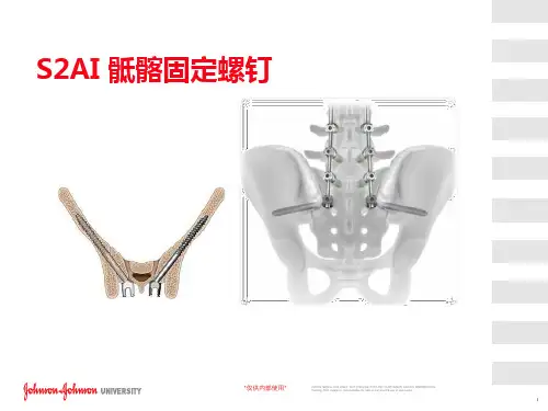
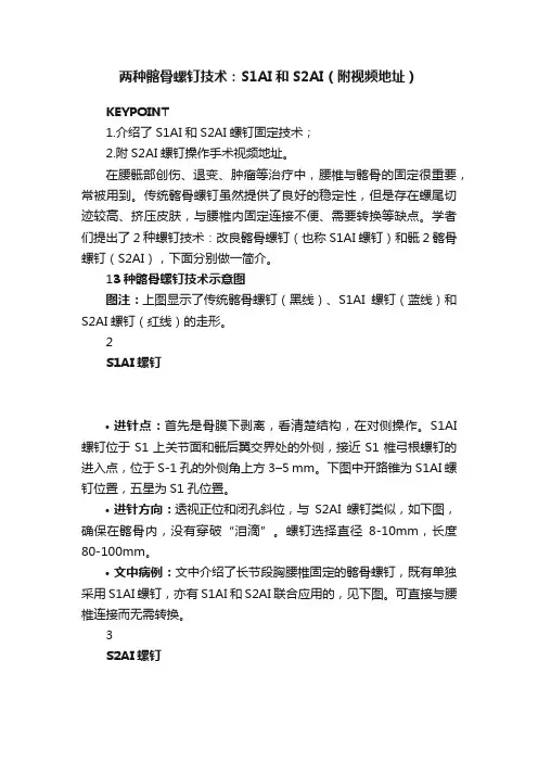
两种髂骨螺钉技术:S1AI和S2AI(附视频地址)KEYPOINT1.介绍了S1AI和S2AI螺钉固定技术;2.附S2AI螺钉操作手术视频地址。
在腰骶部创伤、退变、肿瘤等治疗中,腰椎与髂骨的固定很重要,常被用到。
传统髂骨螺钉虽然提供了良好的稳定性,但是存在螺尾切迹较高、挤压皮肤,与腰椎内固定连接不便、需要转换等缺点。
学者们提出了2种螺钉技术:改良髂骨螺钉(也称S1AI螺钉)和骶2髂骨螺钉(S2AI),下面分别做一简介。
13种髂骨螺钉技术示意图图注:上图显示了传统髂骨螺钉(黑线)、S1AI螺钉(蓝线)和S2AI螺钉(红线)的走形。
2S1AI螺钉•进针点:首先是骨膜下剥离,看清楚结构,在对侧操作。
S1AI 螺钉位于S1上关节面和骶后翼交界处的外侧,接近S1椎弓根螺钉的进入点,位于S-1孔的外侧角上方3–5 mm。
下图中开路锥为S1AI螺钉位置,五星为S1孔位置。
•进针方向:透视正位和闭孔斜位,与S2AI螺钉类似,如下图,确保在髂骨内,没有穿破“泪滴”。
螺钉选择直径8-10mm,长度80-100mm。
•文中病例:文中介绍了长节段胸腰椎固定的髂骨螺钉,既有单独采用S1AI螺钉,亦有S1AI和S2AI联合应用的,见下图。
可直接与腰椎连接而无需转换。
3S2AI螺钉•进针点:首先是骨膜下剥离,看清楚结构,在对侧操作。
进针点在S1孔和S2孔之间,注意与腰椎和S1螺钉的序列,排列在一条线上便于连接。
•进针方向:冠状面上尾向20-30°,矢状面上外倾角度45°,指向髂前下棘处,约大转子尖部上2指,X臂机可同方向引导开路锥。
采用弯头开路锥,背对盆腔,避免髂骨前壁损伤。
深度到骶髂关节时会有阻力。
透视正位和闭孔斜位,确保在髂骨内,没有穿破“泪滴”。
螺钉选择直径7.5-9mm,长度75-90mm。
下图为S1AI和S2AI进针点和方向对比,需要的话是可以同时植入的,注意进针位置,便于连棒。
下图为一例强直性脊柱炎L5/S1 Anderson损害的翻修病例,短节段固定后出现螺钉松动、神经刺激症状。
椎弓根螺钉进针点技巧
椎弓根螺钉是一种用于治疗脊柱疾病的手术工具。
下面简单介绍一下椎弓根螺钉进针点技巧:
1. 选择进针点:要选择合适的进针点,通常是在椎弓根最高点处,从侧面进针。
2. 定位:在进针前,需要将患者的脊椎进行X光定位,确定
进针点和进针角度。
3. 进针:在无菌条件下,使用术前测量好的椎弓根螺钉进行进针。
进针时要调整好进针角度,注意不要将钉头打穿椎板。
4. 固定:将椎弓根螺钉固定在椎弓根处,确保固定牢固且稳定。
总之,在进行椎弓根螺钉进针前,需要仔细评估患者病情和手术风险,规划好手术方案,避免出现手术并发症。
经皮螺钉内固定治疗骶髂关节脱位的护理随着现代社会的发展,交通意外、高处坠落和塌方等各种因素引起的骨盆外伤特别严重,且大多合并有骶髂关节的脱位[1]。
骶髂关节对于骨盆的稳定作用占60% 骶髂关节损伤,常合并全身其他脏器和骨盆前环的损伤,病情重、复杂。
X线机引导下行经皮空心螺钉内固定治疗具有手术时间短、损伤少、出血少、固定可靠、恢复快的优点。
2010年2月至2011年2月我科采用经皮空心螺钉内固定治疗骶髂关节脱位15例,以及配合加强术前术后护理取得满意效果,现将护理方法总结如下:1 临床资料本组15例,男9例,女6例。
年龄20~50岁,平均35.2岁。
致伤原因:交通事故10例,高空坠落伤5例,砸压伤1例。
其中合并失血性休克?,尿道损伤3例,四肢骨折2例。
2 护理体会2.1术前护理2.1.1心理护理:由于患者突遭意外伤害,对疼痛及疾病愈合及高昂费用的担心,产生焦虑与恐惧的心理。
病人的负性情绪对骨折的愈合及伤者的生活质量有一定的影响。
护理人员应及时的跟患者沟通了解患者心理变化,做好相关病房环境及疾病的介绍,使之尽快熟悉病房环境及工作人员,了解疾病的治疗方法。
取得患者对我们医护人员的信任和支持,减轻患者的焦虑与恐惧的心理,使患者以稳定的情绪配合各项治疗和护理。
2.1.2一般护理:①患者卧床休息,尽量减少搬动,以免因过度的搬动加重患者骨折周围及软组织损伤,造成骨折创面出血。
②迅速建立静脉通道,快速输液输血,纠正休克。
③引导病人平卧大小便。
指导病人多饮水,多食粗粮,防止尿路感染及便秘。
④予患者卧海绵垫,水垫局部减压,病情危重的予卧气垫床。
2.2术前准备:术前禁食禁水6-8小时,做好术前皮肤清洁、剔去手术部位毛发(术前备皮),做好交叉配血、药敏试验(皮试),术前留置尿管。
2.3术后护理2.3.1 一般护理:①了解术中经过及麻醉情况;②予低流量氧气吸入、床边心电监护,密切观察患者的生命体征;③观察患者的伤口敷料及伤口引流管情况;④观察患者有无腹痛、腹胀等不适;⑤观察患者上下肢的感觉运动情况。
让你秒懂的骶椎椎⼸根钉固定技术详解作者:雷伟医学博⼠,脊柱外科专家,教授、主任医师,博⼠研究⽣导师,西京⾻科医院副院长,西外科学教研室常务副主任。
出处:《脊柱内固定应⽤指南》权限:《⾻今中外》已获得作者对本⽂的转载授权。
⼀、骶椎椎⼸根的相关数据(图1ABCD)骶⾻椎⼸根和骶⾻翼处的⾻量相对较少,因为骶⾻为⽚状⾻,骶⾻椎⼸根螺钉可以从标准的前内侧⽅向拧⼊骶⾻体或⾻岬部,或者从前外⽅进⼊骶⾻翼。
对于任何外侧骶⾻螺钉的放置,最重要的是注意防⽌发⽣医源性损伤神经⾎管结构。
S1椎⼸根⾼度平均值:左侧(2.26±0.27)cm,右侧(2.22±0.21)cm,应⽤的螺钉直径达0.7cm,螺钉亦不易穿出椎⼸根上、下缘。
骶⾻前⽅的神经⾎管和脏器解剖的特点决定S1螺钉放置时可能的最⼤危险性是损伤腰骶神经⼲、髂内静脉和骶髂关节,S1螺钉放置的区域以前内侧最为安全。
除⾮特殊情况,⼀般不进⾏S1节段的固定。
⼆、骶椎椎⼸根螺钉进钉点的定位(图2)对于S1由于解剖上的变异,螺钉可以从不同的点、不同的⽅向进⼊,主要决定于器械和⾻骼的质量。
在骶椎上不同的位置⾻密度有着较⼤的差异,软⾻下⾻最硬,⽽骶⾻侧块相当疏松,有时甚⾄是空的。
⼀般的说,骶椎椎⼸根的进钉点为上关节的外缘切线与上关节下缘⽔平线的交点。
三、骶椎椎⼸根螺钉的进钉⾓度(图3)植⼊⾓度为内倾25°或者在骶⾻翼外侧成⾓35°。
俯卧位时向头侧偏斜25°-30°,瞄向骶⾻岬,进⼊软⾻下⾻。
四、骶椎椎⼸根螺钉的进钉深度:⼀般情况下为30-35mm深度。
五、骶椎椎⼸根螺钉的直径选择:最常选⽤的螺钉直径为6.5-7.0mm。
六、⼿术操作步骤(具体操作步骤及注意事项见腰椎椎⼸根钉技术)1、确认进钉点2、预备螺钉钉道a.去除⽪质⾻(图4)b.钻孔(图5)c.定位(图6)3、螺钉的植⼊(图7)七、标准椎⼸根螺钉的影像学(图8ABCDEF)。
骶1椎⼸根螺钉固定⽅式今天我们讨论⼀个较为基础但⾮常重要的问题,在做脊柱⼿术的时候经常需要,固定到第⼀骶⾻(以下称S1),这时候我们经常使⽤椎⼸根钉(以下简称螺钉)。
但是骶1螺钉的植⼊⽅式,在临床实践中,存在着⼀些不同。
⾸先我们来看下⾯这张⽚⼦。
这是⼀张腰5/骶1椎间盘突出合并椎管狭窄TLIF的术后⽚⼦,⼤家看有什么问题呢?有⼈可能会觉得⽚⼦好像没什么问题,平时⾃⼰也是这么⼲的。
今天的题⽬是S1螺钉,那咱们对这个⽚⼦上的S1螺钉的固定⽅式上有没有什么不⼀样的看法呢?我们先来简单复习⼀下骶⾻的解剖以及周围的解剖结构:骶⾻由5块骶椎融合⽽成,分骶⾻底、侧部、骶⾻尖、盆⾯和背侧⾯,呈倒三⾓形,我们从盆⾯看⽐较主要的结构就是上关节突、骶翼、还有骶⾻岬。
从背侧⾯看,也能看到上关节突,⽿状⾯,骶⾻粗隆,中间的是骶正中脊,骶正中脊两侧分布4对骶孔,有骶神经的前后⽀通过。
骶⾻周围⽐较重要的神经结构有,骶⾻岬两侧的臀上、下神经,骶孔有骶神经前、后⽀通过,骶⾻邻近的神经还有腰骶⼲、腰5脊神经。
⾎管主要分布在盆⾯,主要有在骶⾻岬最中间的骶正中动、静脉,腹主动脉在L5椎体前缘处往下分⽀成髂总动、静脉,再往下是髂内、外动、静脉,这是我们在⼿术中要密切注意避免损伤的⾎管。
这⾥有⼀个安全区域的概念,就是髂内静脉到骶⾻岬正中间,平均宽度约为24.5mm,如果我们从后路第⼀骶孔上缘向前进针,为了不伤及前⽅⾎管,⾓度需要保持在偏内7°到38°之间,这个后⾯还会提到。
接下来我们看骶1螺钉固定的进针点,⼀般有第⼀投影区和第⼆投影区两个区域,他们的界限就像这个图上表⽰的:第⼀区:(上)骶⾻翼上切迹(下)第⼀骶孔上缘(外)S1关节突外侧缘(内)外侧缘向内约11mm。
第⼆区的上下界和第⼀区是相同的,它的内侧缘就是第⼀区的外侧缘,它的外侧缘呢就是向外约15mm。
找到进针点以后咱们就要明确进针⽅向,从⽮状⾯看呢⼤体分为3种:1、由骶⾻后缘第⼀投影区与骶⾻底平⾏,向骶⾻岬钻⼊2、第⼆种和第⼀种的区别只有进针点不同,进针点选择第2投影区3、由骶⾻后缘第⼆投影区为进针点使⽤PTSF螺钉置⼊技术(骶⾻螺钉钻向前内侧朝向骶⾻岬,穿过腰5骶1椎间盘直⾄腰5椎体前缘, 但并不穿透腰5前缘的⾻⽪质的⼀种⽅法),多⽤于中重度的椎体滑脱关于选择内侧置钉还是外侧置钉,从早期到现在都存在争论,国内外的医⽣们都持不⼀样的态度,但是我所了解到的现在的主流还是向内侧置钉。
C 臂机引导骶髂螺钉经皮闭合穿钉治疗骶髂关节脱位何栩岚(浙江省余姚市人民医院,浙江余姚,315400) 关键词:C 臂机;骶髂螺钉;经皮闭合穿钉;骶髂关节脱位 中图分类号:R 68417 文献标识码:A 文章编号:1672Ο2353(2008)07Ο0104Ο02 随着现代社会的高度发展,交通工具意外引起的高能量创伤、高处坠落以及生产事故等引起严重的多脏器、多组织的损伤,往往并发骶髂关节骨折、脱位,在救治病员的过程中,病人的生命体征常不稳定,如何采用合适的治疗方式在治疗骨盆骨折的同时,又减少对患者生命的威胁,一直以来在不断的探索。
以往采用保守治疗方法,远期疗效并不令人满意,现在多倾向于手术复位内固定治疗[1Ο3],作者开展的C 臂机引导下微创经皮置入骶髂拉力螺钉内固定治疗骶髂关节脱位取得成功,其操作简便,损伤小,预后好而值得推广应用。
1 临床资料选择我院创伤科病房2004年3月~2007年7月住院期间符合骨盆骨折(Tile 分类C 型)诊断标准的患者17例。
本组男12例,女5例;年龄17~59岁,平均31.8岁;交通损伤11例,高处坠落伤3例,其他类型损伤3例。
所选病例均为骨盆后环损伤伴骶骨骨折或骶髂关节处髂骨骨折,其中4例伴有腹腔脏器损伤,2例伴有尿道损伤,1例伴有骶神经损伤。
伤后至手术时间为1~30d ,平均7.5d 。
术后住院时间6~29d ,平均15.5d 。
术前常规对患者生命体征进行评估。
采用全麻或硬膜外麻醉,患者一般取俯卧位,患肢置于骨科外展牵引床上行术前牵引,C 臂机透视显示骨盆后环移位基本纠正(移位或脱位<0.5cm)后方可手术。
常规消毒铺单,取骶1椎弓根轴线与髂骨翼后外侧面的交点为骶髂螺钉的进针点,此处做1~1.5cm 小切口。
在C 臂机引导下应用2.5mm 导针由切口钻入髂骨,导针角度根据C 臂机透视下进行调整,导针经髂骨、骶髂关节钻人S1椎体。
透视下,骨盆正位片上显示导针应止于S 中线附近,骨盆侧位导针位于骶管前方S1椎体内。
Injury,Int.J.Care Injured(2004)35,S-A46—S-A560020–1383/$—see front matterß2004Published by Elsevier Ltd. doi:10.1016/j.injury.2004.05.010For musculoskeletal tumor resections, it is rather difficult to define the exact resection line because normal and cancerous bone can hardly be differenti-ated in most cases. With exact resection, however, the preservation of osseous structures, eg, parts of the sacrum, is possible as well as preservation of nerve roots.Navigation procedures based on CT data are well proven in spinal surgery. With reduced radiation exposure, the precision can be enhanced [3]. In our own clinical practice, CT-based navigation is part of the clinical routine for dorsal spine instrumenta-tion. Between May and December 2000, 124 out of 126 pedicle screws inserted in the thoracic spine were placed correctly [13]. Based on these good experiences, CT-based navigation was used in pelvic surgery as well.Fluoroscopy-based n avigation o ffers t he a dvantage that the fluoroscope is already present in the operat-ing room (OR) and current images can be acquired whenever needed. Up to four C-arm projections can be displayed simultaneously on the navigation screen. Therefore, no intraoperative re-orientation of the fluoroscope is needed. After experimental definition of adequate fluoroscopy projections for five typical pelvic screws [12], fluoroscopy-based navigation was used in the clinical set-up. Modality-based navigation uses a specially de-signed and equipped CT-suite as an OR. Navigation is performed on the basis of the CT data with the possibility of immediate CT-control of the reduction and the navigation procedure as well.The clinical experiences with the different naviga-tion techniques in pelvic surgery are described with a particular focus on indications, operative technique, and limitations.Methods an d r e l e van t in d ica t i o n s Between June 1st, 2000 and December 31st, 2002 there were 41 percutaneous screw fixations per-formed with either CT- or fluoroscopy-based navi-gation.Ac et abular frac t ur e P e lvic ringinjurySIar th r os i snCT-ba sednaviga t i o n3115Flu o r os c o py-ba sed naviga t i o n820836 n1121941 T able 1: Indications for navigated screw fixations.Three musculoskeletal tumors were resected us-ing CT-based navigation. There were two chordomas of the sacrum and one Ewing sarcoma of the iliac wing.CT-ba sed naviga t i o nFor CT-based navigation, the CT-based spine module of Medivision® can be used. CT data with at least 2mm slices was transferred to the workstation. Within the 3-D reconstruction, the reference points for the paired point matching have to be defined and the preoperative planning performed. For per-cutaneous procedures, we recommend positioning the reference points along the iliac crest, which is easily accessed with small skin incisions. In addition to the palpable anterior superior iliac spine, ad-ditional points in a defined distance along the iliac crest are recommended. Marker screws can be used but have the disadvantage of an additional operative procedure before the CT. For tumor resections, the reference points were defined within the operative area. For surface matching, 15–20 points were ac-quired with the pointer. These points were located in the area of the reference points or in the operative area as well. After successful matching and verifi-cation, the navigated procedure was started. The fluoroscope was left in the OR-setup for the whole procedure to enable intraoperative control of the position of the guided instruments.Flu o r os c o py-ba sed naviga t i o nA conventional fluoroscope was used (Ziehm®) and the C-arm navigation module was from Medivision®. Optoelectronic markers were mounted onto the instruments, the dynamic reference base, and the fluoroscope. An infrared camera assessed the posi-tion in space. Up to four fluoroscopy projections can be displayed simultaneously on the navigation screen. The direction and length of the navigated drill or drill sleeve can be followed on the screen and thus be controlled in all four projections without additional imaging.S et-up(Fig.1)All navigated procedures need to be planned in advance regarding the set-up in the OR. For navi-gated pelvic surgery, the optoelectronic camera is positioned at the feet of the patient with about 2 m distance to the dynamic reference base, mostly mounted in the iliac crest of the side to be operatedon. The surgeon is on the operative side, with the fluoroscopy and navigation monitor positioned on the opposite side.Op e ra t iv e te c h niqu e f o r s cr e w fixa t i o n sFor screw fixations, 7.3 mm cannulated screws were used with a 2.8 mm guidewire. As preclinical tests showed deviations of the guidewire from the planned course in the bone, the technique for navigated cannulated screws was changed. After successful matching or acquisition of the appropriate fluor-oscopy projections, the correct skin incision point is defined with the navigated pointer . After skin incision and blunt dissection, the osseous entrance point was marked and the navigated drilling was performed with a specially reinforced drill and the referenced machine. In case of sacroiliac screws (SI), the drilling was just executed across the SI joint. After inserting the guidewire into the drill and fluoroscopic control of the position, the cannulated screw was inserted.Within the series, we noticed that movements with the navigated machine led to misleading changes in the screen display for navigation even though direction of the drill was unchanged (Fig. 2a). Therefore, a referenced drill sleeve was developed (Fig. 2b). This drill sleeve was inserted with a blunt trocar and had several sharp tips at the end for se-cure anchoring in the bone. Other than that point, the technique remained the same.T o assess the precision of the procedures, all screws were controlled with CT . For fluoroscopy-based navigation, fluoroscopy images, navigation screens, and postoperative x-rays were also com-pared.Fig. 1: OR–setup for navigation.Fig. 2: Technique a) M ovement of the referenced machine without chang-ing the effective direction of the drill, but with a clear change on the navigation screen. b) N ew developed navigated drill sleeve for percutaneous screw fixations.Fig 3: Modality-based navigation. 51-year-old patient, roofer, fell off a roof and was treated conservatively over several weeks for a sac-ral fracture. Fol-lowing persistent severe pain, decision to carry out a CT-control-led, navigated osteosynthesis. As a result the patient became pain-free and fit for work.4a) Pelvic x-ray after SI fixation right, matching within the surgical approach on the left side. 4b) Defining of the skin incision point according to the preoperative planning.4c) Intraoperative navigation with guidance and realtime modusFig. 4 a—e: CT-based navigation for transiliosacral screw.For painful bilateral SI arthrosis probatory SI screw fixation right was already performed with pain relief indication for definitive SI stabilisation bilateral. Inserting of the left SI screw with CT based navigation.d) After drilling with the reinforced navigation drill, inserting of the guide wire and the cannulated screwe) Postoperative x-ray after bilateral SI stabilisation , postoperative CT with correct position of the SI screw left,identical to the planning.Within the tumor cases, the resection lines were defined with navigated chisels as planned preopera-tively after successful matching and verification. Postoperatively , the resection areas were examined histologically .Mod ali t y-ba sed naviga t i o n (Fig. 3)The method of modality-based navigation is differ-ent to the above-mentioned techniques. Surgery is performed within a specially equipped CT-suite or in an OR with integrated CT . The patient is positioned on the CT table and the instruments are navigatedon the basis of the CT data, with the opportunity for immediate CT control of reduction maneuvers as well as all operative steps (Fig. 3).R es ul tsCT-ba sed naviga t i o n (Fig. 4, 5)With CT-based navigation, two percutaneous screw fixations of minimally displaced acetabular fractures were performed. One case was an anterior column fracture, the other a transverse fracture. For the an-a) Pelvic x-ray and CT after neoadjuvant treatment (Euro Ewing Schema).b) MRI and intraoperative situsFig. 5 a—d: 21-year-old patient with Ewing sarcoma of the right iliac wing.terior column fracture, one screw was inserted, and for the transverse fracture, two screws. The match-ing procedure was successful in both cases with two small incisions at the iliac crest. During the verifica-tion procedure we figured out that navigation is only possible with all points of the surface matching on the side to be operated on. With surface points on the contralateral side, the navigation display did not correspond with intraoperative fluoroscopy control, despite good matching results. The position of all the navigated screws was correct and perfectly cor-responded with the preoperative planning.In two cases, percutaneous SI screw fixations were performedusingCT-basednavigation. The indica-tions were one iliosacral dislocation fracture and one iliosacral arthrosis. In these cases, the matching5c) Defining of the resection lines with CT-based navigation.5d) Pelvic resection type IV Eneking and Dunham, postop-erative x-ray after stabilisation with two fibula grafts and distractionsspondylodesis.was also successful, with the first trial using two additional skin incisions at the iliac crest. The place-ment of the screws was identical to the preoperative planning (Fig. 4e).For tumor resections, paired point andsurfacematchingoccurredwithout any problems. The resec-tion line was exactly defined as planned preopera-tively . The histological examination revealed tumorfree resection lines in all cases. In the patient with the Ewing sarcoma in the iliac wing, the continuity of the pelvic ring was reconstructed with two fibula grafts.Flu o r os c o py-ba sed naviga t i o n(Fig.6)With fluoroscopy-based navigation, eight percuta-neous screw fixations were performed for acetabular fractures, and 28 transiliosacral screws were placed with 27 in S1 and one in S2.In one case of an iliosacral dislocation fracture, malreduction of the posterior pelvic ring was only noticed in the postoperative x-ray. Because of the re-duced image quality due to the navigation markers, it was not recognized intraoperatively. The revision surgery was then performed in the conventional way. In one patient with bilateral transforaminal sacral fractures and bilateral SI screws, the position of the screws was stated correctly in the postoperative x-rays (inlet, outlet view), whereas the CT showed an anterior cortex perforation of the sacrum on one side. With otherwise good reduction and because of the absence of neurological symptoms the screw was left in place.Except for this one misplacement, 35 of the 36 screws placed with fluoroscopy-based navigation were positioned correctly in x-ray and CT control. The average fluoroscopy time per procedure was 0.5 min.Di s cu ss i o nThe most frequent application of percutaneous screws in the pelvis are transiliosacral screws for minimally displaced sacral fractures or SI disrup-a) Pelvic x-ray and CT.b) Acquisition of the fluoroscopyprojections.c) I ntraoperative navigation screen forSI screw fixation right, postopera-tive x-ray.Fig. 6 a—c: Unstable pelvic injury with sacral fracture (C1.3).tions, which can be reduced by closed maneuvers [1, 8—10]. However, percutaneous screws are also used for acetabular fractures with appropriate frac-ture configuration and possible closed reduction [2, 7, 11]. For minimally displaced acetabular fractures, the aim of the percutaneous stabilization is early mobilization. As percutaneous pelvic stabilization is a technically ambitious procedure because of the pelvic geometry, average fluoroscopy times between 1.4 and 4.4 min per procedure are reported [8, 9, 11].CT-based navigation allows a procedure with high precision, especially in cases with no or minimally displaced fractures [1, 2, 6]. The matching proce-dure can be difficult because the osseous pelvis is surrounded by spacious soft tissues. Either fiducials can be used or it is necessary to define points along the iliac crest that are easily accessible through small skin incisions. For reduction maneuvers, a new CT dataset is necessary after each manipulation. Therefore, a CT needs to be available in the OR, resulting in concomitant logistical problems.In tumor surgery, a differentiation of intact or infil-trated bony surface can be difficult but is necessary to define the resection line. CT-based navigation can use the information from the CT intraoperatively. With additional visualization, the resection line can be planned exactly and executed safely. The match-ing procedure is easy to perform within the operative approach. In our three cases, the resection was per-formed according to the preoperative planning with histologically safe resection areas. With the fusion of additional imaging modalities like MRI, navigation procedures will be of increasing benefit even for soft tissue tumor surgery, especially when intraoperative referencing with ultrasound is possible.For fluoroscopy-based navigation, good quality of the defined fluoroscopy projections is mandatory for safe and precise screw positioning. In cases of insufficient image quality, the navigated procedure may not be performed. With good image quality, however, the pelvic screws, mainly SI screws, can be inserted securely and precisely with an average fluoroscopy time of 0.5 min per screw. This is a clear advantage compared to conventional procedures [8, 9]. For sacral dysplasia, which can be detected in CT, CT-based navigation is to be preferred.For both procedures, CT-based as well as fluor-oscopy-based, the fluoroscope remains in the OR throughout the procedure. The navigation system is an additional tool to enhance the precision with decreased radiation exposure. The navigation sys-tem itself cannot guarantee a 100% precision, not even with good matching values for registration. Unnoticed manipulations of the dynamic reference base, for example, can lead to a complete shift of the image. The navigation screen always displays a ‘virtual reality’, whereas the fluoroscope shows the real situation. T o avoid severe misplacements as described by other groups [3], it is therefore strongly recommended to leave the fluoroscope in the set-up and to control the operative steps in at least one projection.For percutaneous screw fixations, the described technique with the navigated drill sleeve and reinforced drill is recommended. Because of the tendency of the guidewire to bend, it is necessary to start the procedure with the cannulated drill to effectively use the advantages of the additional visualization with navigation.Overall, the results of the fluoroscopy-based navigation are very satisfying for the technically ambitious application of percutaneous pelvic screws with 35 of 36 screws placed correctly. With just 0.5 min radiation exposure, high precision of the screws was achieved. With further improvements in image quality and some technical changes, a further im-provement in precision is to be expected.The Siemens Iso C 3-D fluoroscope combines the advantages of CT- and fluoroscopy-based naviga-tion. It offers the advantage of axial cuts, 2-D and 3-D reconstructions, and enables immediate reduc-tion control. The image quality is clearly decreased compared to the CT but is sufficient to assess the reduction quality in the posterior pelvic ring and to navigate on the basis of these images. The first clini-cal cases are promising, and further clinical studies will show the potential of this new method, not only in pelvic surgery.CT ba sed Flu o r os c o pyba sedMod ali t yba sedA d van t ag es• P reoperativeplanning• A xial cuts• 3-Dreconstruction• N o matching• A ll timeupdatepossible• G oodreductioncontrolDi s a d van-t ag es• M atchingnecessary• N o updatewithout CT• N o axialcuts• L imitedimagequality• L imitationsforreductionmaneuversIn d ica t i o n s• N on-displacedfractures• D ysplasia• T umorresections• D isplacedfractures• S tandardprojections• A llfractureswith minorreductionsT able 2: Indications for navigation procedures in pelvic surgery.Modality-based navigation offers the opportu-nity for immediate CT control of all operative steps. Especially for the posterior pelvic ring, this is a clear advantage compared to the two other methods. Weknow that about 30% of all sacral fractures can only be detected in CT and only with the axial cuts and 2-D reconstructions of CT data can the reduction quality of the posterior ring be assessed adequately in all cases. Image quality is still the limiting factor for fluoroscopy and the Iso C 3-D offers the ability for axial and 2-D reconstructions, but image quality is clearly decreased compared to CT.For percutaneous pelvic surgery, modality-based navigation is the best method in terms of immediate quality control. But one has to take into account that a special CT suite or an interventional OR with CT is necessary for these procedures with some associated logistical problems. Limitations regarding reduction techniques and open surgical procedures need to be dealt with as well. R e f e r e nc es1. Ebrahim NA, Coombs R, Jackson WT, et al. (1994) Percutane-ous computed tomography-guided stabilization of posterior pelvic fractures. Clin Orthop; 07: 222–228.2. Gay SB, Sistrom C, Wang GJ, et al. (1992) Percutaneous screwfixation of acetabular fractures with CT-guidance: prelimi-nary results of a new technique. J Roentgenol [Am];158(4): 819–822.3. Gebhard F, Kinzl L, Arand M (2000) Computerassistierte Chiru-rgie. Unfallchirurg; 103: 612–617.4. Hamadeh A, Lavallee S, Cinquin P (1999) Automated 3-di-mensional computed tomographic and fluoroscopic image registration. Comp Aided Surg; 4(2): 65–76.5. Hofstetter R, Slomczykowski M, Sati M, et al. (1999) Fluor-oscopy as an imaging means for computed assisted surgical navigation. Comp Aided Surg;4(2): 65–76.6. Jacob AL, Messmer P, Stock KW, et al. (1997) Posterior pelvicring fractures: closed reduction and percutaneous CT-guided sacroiliac screw fixation. Cardiovasc Intervent Radiol; 20(4): 285–294.7. Parker PJ, Copeland C (1997) Percutaneous fluoroscopic screwfixation of acetabular fractures. Injury; 28(9-10): 597–600.8. Routt ML Jr, Kregor PJ, Simonian PT, et al. (1995) Early resultsof percutaneous iliosacral screws placed with the patient in the supine position. J Orthop Trauma;9(3): 207–214.9. Routt ML Jr, Simonian PT (1996) Closed reduction and per-cutaneous skeletal fixation of sacral fractures. Clin Orthop;329:121–128.10. Shuler TE, Boone DC, Gruen GS, et al. (1995) Percutaneousiliosacral screw fixation; early treatment for unstable poste-rior pelvic ring disruptions. J Trauma; 38(3): 453–458.11. Starr AJ, Reinert CM, Jones AL (1998) Percutaneous fixationof the columns of the acetabulum: a new technique. J Orthop Trauma; 12(1): 51–58.12. Stöckle U, König B, Hofstetter R, et al. (2001) Bildwandler-basierte Navigation: Eine experimentelle Studie zu Becken-verschraubungen. Unfallchirurg; 104: 215–220.13. Stöckle U, König B, Kandziora F, et al. (2001) Clinical experi-ences with CT-based navigation in the thoracic spine. Comp Aid Surg; 6: 120.14. Suhm N, Jacob AL, Nolte LP, et al. (2000) Surgical navigationbased on fluoroscopy: clinical application for computer-as-sisted distal locking of intramedullary nails. Comp Aid Surg;5: 391–400.Correspondence address:Priv. Doz. Dr. Ulrich StöckleZentrum für Muskuloskeletale ChirurgieCHARITÉ — Universitätsmedizin BerlinCampus Virchow KlinikumAugustenburgerpl.113353 Berlin, Germanyphone: 030 450 52033fax: 030 450 52901email: ulrich.stoeckle@charite.de。