新力川-说明书(修改简洁版3)
- 格式:pdf
- 大小:10.93 MB
- 文档页数:22
药品补充申请—5、10 申报资料3变更药品规格(增加薄膜衣)变更直接接触药品的包装材料或者容器(薄膜衣片增加铝塑泡罩包装)修订的药品说明书样稿及修订说明××××制药有限公司××年××月一、卡托普利片说明书样稿核准日期:卡托普利片说明书请仔细阅读说明书并在医师指导下使用【药品名称】通用名:卡托普利片英文名:Captopril Tablets汉语拼音:katuopuli pian【成份】本品主要成份为卡托普利。
化学名称:1-[(2S)-2-甲基-3-巯基-1-氧化丙基]-L-脯氨酸。
化学结构式:分子式:C9H15NO3S分子量:217.29【性状】本品为薄膜衣片,除去薄膜衣后显白色或类白色。
【适应症】1.高血压;2.心力衰竭。
【规格】25mg。
【用法与用量】视病情或个体差异而定。
本品宜在医师指导或监护下服用,给药剂量须遵循个体化原则,按疗效而予以调整。
1.成人常用量:(1)高血压,口服一次12.5mg(半片),每日2—3次,按需要1—2周内增至50mg(2片),每日2—3次,疗效仍不满意时可加用其他降压药。
(2)心力衰竭,开始一次口服12.5mg(半片)每日2—3次,必要时逐渐增至50mg(2片),每日2—3次,若需进一步加量,宜观察疗效2周后再考虑;对近期大量服用利尿剂,处于低钠/低血容量,而血压正常或偏低的患者,初始剂量宜用6.25mg每日3次,以后通过测试逐步增加至常用量。
2.小儿常用量:降压与治疗心力衰竭,均开始按体重0.3mg/kg,每日3次,必要时,每隔8—24小时增加0.3mg/kg,求得最低有效量。
【不良反应】1.较常见的有:(1)皮疹,可能伴有瘙痒和发热,常发生于治疗4周内,呈斑丘疹或荨麻疹,减量、停药或给抗组胺药后消失,7%—10%伴嗜酸性细胞增多或抗核抗体阳性。
(2)心悸,心动过速,胸痛。
(3)咳嗽。

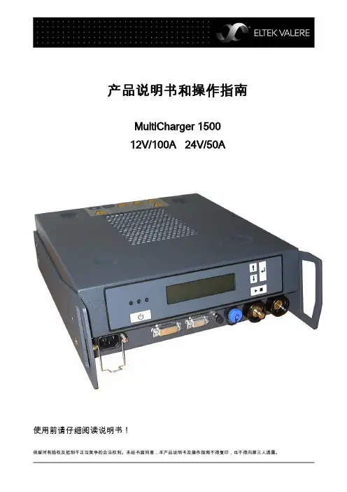
产品说明书和操作指南MultiCharger 150012V/100A 24V/50A使用前请仔细阅读说明书!保留所有版权及抵制不正当竞争的合法权利。
未经书面同意,本产品说明书及操作指南不得复印,也不得向第三人透露。
版本说明MultiCharger 1500EVD-No.: 811-0206-0Doc-No.: 2075354.01© December 2009 by Eltek Valere Deutschland GmbH 编号: 0109ELTEK VALERE DEUTSCHLAND GMBHFerdinand-Porsche-Straße 45 Postfach (PO Box) 61 06 51 D-60386 Frankfurt am Main D-60348 Frankfurt am MainTelefon-Nr. : +49 69 42002-0Fax-Nr. : +49 69 42002-389E-mail : info@eltekvalere.deweb : http://www.eltekvalere.de一般安全说明仅只能连接额定电压为12V和24V的电池。
注意——仅只能连接可充电电池。
注意——有形成爆鸣气体的危险:1. 连接及断开电池馈电线时,要断开电源。
2. 如电池是安装在车内的,则首先按照极性标识,将充电器的充电线与电池的正极(+)连接(不要与汽车底盘连接)。
然后,将负线与电池的负极(-)连接。
不要连接到汽化器或燃油管上。
充电完毕后,首先取下负线(底盘侧的线)。
(如电池是安装在车内的,则首先按照极性标识,将充电器的充电线与电池极进行连接,并使充电器进入待用状态。
在充电过程中,不要取下电池夹。
只是在充电器失活后以及断开电源后,方才取下电池夹。
)3. 不要使电池过度充电——参阅使用说明。
4. 电池附近禁止吸烟。
避免明火及火花。
5. 仅只在通风良好处使用。
休闲裤贴袋机Chino Pocket Setter (MB1002D-1-S7300A-305P)使用说明书Instruction Manual常州智谷机电科技有限公司CHANGZHOU WISDOM &VALLEY ELECTRICAL TECHNOLOGY CO.,LTD在使用本设备之前请先阅读本使用说明书Please read the operation manual of the touch screen interface before using the device 请将本使用说明书放在便于查阅的地方保管Please keep this operation manual of touch screen interface in convenient placeforreference2020.03版本信息/Version感谢购买IMB工业用缝纫机。
在使用此机器之前,请仔细阅读以下的说明,这样可以更好地帮到您了解此机器的相关操作。
这些说明是根据现行的条例明确阐述了正确的工作方法。
Thank you for purchasing this industrial sewing machine from IMBBefore using this automatic unit,please read the following instructions,which will help you tounderstand how the machine operates.These instructions illustrate the correct working methods to comply with current regulations.在没有得到IMB授权许可的前提下,此说明书的任何部分是不可以被复制或者转录的。
说明书的内容可能被修改,而不需预先通知。
No part of this manual may be copied or transcribed without requesting prior authorization from IMBThe contents of this manual may be subject to change without advance notification.我们将欣然接受各位提出的改进此说明书的任何建议和指示We are happy to receive suggestions and/or indications on ways we could improve this manual.本机介绍说明分为三部分,具体请参照《MB1002D休闲裤贴袋机-使用说明书》、《MB1002D休闲裤贴袋机-零件手册》、《MB1002D休闲裤贴袋机-触摸屏界面操作说明》。
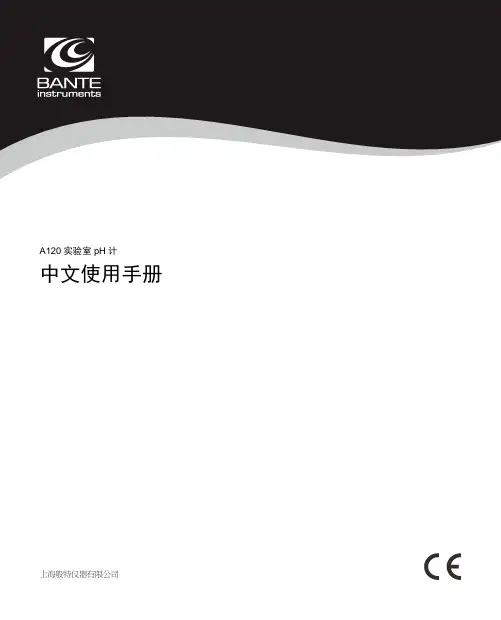
A120实验室pH计中文使用手册简介感谢您选择般特仪器的A120实验室pH计,这本操作手册循序渐进的描述了仪表的各项功能与特征。
使用前,请仔细阅读。
使用环境打开包装前,请确保当前工作环境符合以下条件:•相对湿度小于80%•环境温度大于0°C并且小于60°C•无潜在的电磁干扰装箱单以下列表描述了仪表出厂时的标准组件。
拆箱后,请检查所有部件是否齐全。
如有缺失或损坏,请立即联络般特仪器授权销售商。
A120 pH计电极架pH标准缓冲试剂pH电极TP-10K温度探棒DC12V电源适配器按键功能连接器安装电极架取出包装盒内的电极架。
翻转仪表,对准电极架底座与仪表的圆孔,将2颗螺钉适度拧入。
安装后,如果电极臂自动升起或落下,您需要适度调节电极架内的螺钉直至电极臂可以在任何位置定位。
1. 取下电极臂右侧的塑胶盖。
2. 使用十字螺丝刀适度拧紧螺钉。
3. 安装塑胶盖至先前的位置。
连接电极1. 取出包装盒内的pH电极,按下述步骤将电极插入电极臂的左或右侧。
1. 插入电极2. 勾入线缆3. 勾入线缆2. 将电极的BNC连接器插入仪表背面板标有pH/ISE的连接器座,顺时针旋转并锁紧。
连接完成后,请勿拉拽线缆,始终保持连接器清洁、干燥。
连接温度探棒1. 取出包装盒内的温度探棒并插入电极臂中间的圆孔。
2. 将温度探棒的连接器插入仪表背面板标有°C的连接器座,确保连接器完全就位。
连接电源适配器1. 连接电源适配器前,请确保其电压及规格符合您所在国家的供电要求。
2. 将电源适配器插入电源座,仪表现在可以使用了。
开关仪表• 按住键,仪表开机,屏幕显示测量值。
• 按住键3秒,仪表关机。
如果您需要启用自动关机功能,请参阅【设置菜单】一节所述。
设置菜单A120 pH 计包含一个完整的设置菜单用于自定义各项参数以符合测量需求,以下列表描述了各菜单项的功能。
设置默认选项1. 在测量模式,按住键3秒进入设置菜单。
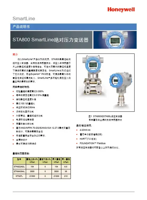

美格— 62使用说明书感谢选用美格62产品。
MEGA62是本公司继MEGA64之后又一鼎力之作。
为当今供水行业顶级专家厚积薄发,博采众家之长,精心打造的恒压供水行业的航空母舰。
该控制器性能卓越,功能强大,为简单应用用户提供更加稳定可靠的性能;为复杂尖端应用用户提供了更加灵活自由的供水设计解决方案。
62沿用了64蓝底白字四行八位的液晶屏全中文显示模式,并可直接挂接彩色触摸屏,操作更加直观简单方便。
该机器具有如下功能特点:1、多泵组设计,六台大泵加两台附属小泵,大泵、小泵皆可变频工频任意状态设定。
所有泵皆可实现故障互投或作处理对策。
2、分体结构,主机与显示器或触摸屏、上位机可分离。
专家自整定+模糊控制+现场优化经验处理,更符合供水控制特点。
3、界面美观,操作直观,全中文显示,分级菜单设定,无底层代码,无说明书也能自如设定应用;高低级功能设置,特殊场合亦可满足复杂要求。
4、控制模式、停车方式、大小分时、实时时间、目标值、当前值、频率、泵状态、各种报警均可同步显示;换泵倒计时、巡检倒计时、公司信息、电话、消防、休眠等等一目了然。
5、控制安全,各种工况处理对策可选。
6、双恒压可选,可通过开关量设定稳压值,或者决定消防功能启用与关闭。
7、多达八时段压力控制,且每时段内均可进行任意的压力设定控制及实现八时段的定时开关机功能。
8、智能节能休眠模式,解决行业内高层建筑休眠难题;主泵、小泵皆可休眠,小泵变量亦可休眠;压力提升休眠模式,并可控制小泵进休眠状态时间。
9、大小泵优先选项,并可锁定、禁止小泵运行时段,智能的定时换泵及独特的夜间换泵功能,正负反馈方式。
10、无负压功能,支持电接点或第二模拟量输入模式,且二者皆可自由设定;消防及巡检功能,消防泵巡检间隔及时长可随意设定,符合公安部最新消防标准。
11、延时启动功能,软停车功能,解决高层水锤及保护管网,获得平稳控制效果。
12、自动抑制表头抖动及系统振荡,让系统更稳定,模拟输出增益更宽可调。
力比泰(Alimta)的中文说明书(上)[药品名称]通用名:注射用培美曲塞二钠商品名:英文:ALIMTA中文:力比泰英文名:Pemetrexed disodium for Injection汉语拼音:Zhu She Yong Pei Mei Qu Sai Er Na本品主要成份为培美曲塞二钠其化学名称及结构式:略分子式:C20H19N5Na2O6·7H2O分子量:597.49[性状]本品为白色至淡黄色或绿黄色冷冻干燥固体。
[药理毒理]药理作用培美曲塞是一种结构上含有核心为吡咯嘧啶基团的抗叶酸制剂,通过破坏细胞内叶酸依赖性的正常代谢过程,抑制细胞复制,从而抑制肿瘤的生长。
体外研究显示,培美曲塞能够抑制胸苷酸合成酶、二氢叶酸还原酶和甘氨酰胺核苷酸甲酰转移酶的活性,这些酶都是合成叶酸所必需的酶,参与胸腺嘧啶核苷酸和嘌吟核苷酸的生物再合成过程,培美曲塞通过运载叶酸的载体和细胞膜上的叶酸结合蛋白运输系统进入细胞内。
一旦培美曲塞进入细胞内,它就在叶酰多谷氨酸合成酶的作用下转化为多谷氨酸的形式。
多谷氨酸存留于细胞内成为胸苷酸合成酶和甘氨酰胺核苷酸甲酰转移酶的抑制剂.,多谷氨酸化在肿瘤细胞内呈现时间-浓度依赖性过程,而在正常组织内浓度很低。
多谷氨酸化代谢物在肿瘤细胞内的半衰期延长,从而也就延长了药物在肿瘤细胞内的作用时间。
临床前研究显示培美曲塞体外可抑制间皮瘤细胞系(MSTO-211H,NCI-H2052)的生长。
间皮瘤细胞系MSTO-211H的研究显示出培美曲塞与顺铂联合有协同作用。
人群药效学分析采用的指标是绝对中性粒细胞计数;此时人群接受的为单药培美曲塞,未接受叶酸和维生素B12的补充治疗。
通过观察粒细胞最低值来判断血液学毒性发生的严重程度,结果发现其与本品全身给药剂量且呈负相关关系。
研究中也发现如果患者基线检查时胱硫醚或高半胱氨酸浓度高,那么其绝对粒细胞计数下降的会更为严重。
叶酸和维生素B12;可以降低胱硫醚或高半胱氨酸这两种底物的浓度。
P .O.Box1306,NewportBeach,California92663•Phone:714-751-0488•Fax:714-957-1621•E-Mail:*********************GALVANIC ISOLATORMODELS: GI-30 and GI-50I NSTALLATION I NSTRUCTIONSGENERAL INFORMATION:The Galvanic Isolator (GI) is a device for reducing stray low voltage currents travel-ing between the shore power’s AC safety ground (earth) and the boat’s DC bond-ing system, while maintaining the safety requirement of an electrical path to ground in the event of a short circuit.These stray currents are a chief cause of destructive galvanic corrosion (sometimes referred to as “electrolysis”) which eats away at sacrifi cial zincs, or if there are none, destroys outdrives, propellers and through-hull fi ttings.Installation of the GI blocks the fl ow of the majority of these stray currents, saving the boater the headaches and costs associated with haul-outs and zinc replacement.The GI uses solid state components housed in a rugged anodized aluminum heat-sink case. 10" heavy gauge input/output leads (GI-30) or 1/4-20 studs (GI-50) are provided for easy in-line installation.The GI is suitable for use with 115 or 230 V AC circuits up to 30 or 50 amps, depend-ing on model, and has been engineered to conform to the latest ABYC (American Boat and Yacht Council) Standards pertaining to boat wiring. These standards specify that a galvanic isolator must be capable of carry-ing 135 % of the rated shore power current, while maintaining a maximum exterior surface temperature of 90° C, in the event of an AC fault condition aboard the vessel. Models GI-30 and GI-50 comply with these standards when utilized in 30 and 50 amps shorepower installations, respectively.INSTALLATION:1) CAUTION: Ensure that the shore power cord is disconnected and that any AC gen-erators or DC-AC power inverters which are routed through the AC distribution panel have been shut down.2) If the shore power inlet housing is a metal enclosure which is tied to the incoming shore ground, verify that it is not tied to boat ground.3) Install the GI on a suitable mounting surface near the boat side of the AC power inlet. Caution: The GI is not to be installed in an area where ignition protection is required. The case of the GI is electrically isolated from the internal components, so it may be mounted on either a metal or non-metal surface.4) Locate the ground wire which normally runs from the AC inlet to the distribution sys-tem/panel. In the USA this wire is always green or green with yellow stripes. In other countries this may vary. (See wiring dia-gram.) Typically, it runs adjacent to the hot and neutral wires. Cut the ground wire.5) IMPORTANT STEP: In order to ensure that the GI will perform as required, you should verify that there is no electrical ground path from shore power ground to boat ground other than through the GI. Therefore, prior prior to installation you should check with an ohm meter to see that there is no continu-ity whatsoever between both ends of the ground wire which was cut in step 4. Ifany continuity is measured, its source must be located and disconnected for the GI to deliver the desired protection.6) Install the GI as shown in the diagram below:IMPORTANT:The Galvanic Isolator is only to be installed by someone knowledgeable and qualifi ed to work with AC circuits. Any questions regarding its suitability for a particular application or its proper installation within a particular circuit must be referred to a qualifi ed marine electrician.TROUBLESHOOTING:To verify the integrity of the GI's internal back-to-back diodes and and capacitor, and hence the continuity of the green wire earth ground, use the following procedure:1) Disconnect shore power and turn off all other on-board sources of AC power. Dis-connect the GI from the ship's wiring.2) Using an analog volt/ohm meter (VOM) set in the Rx1 resistance measuring mode, connect the VOM probes across the GI's two green wires (GI-30) or 1/4" stud posts (GI-50).3) The VOM meter needle should move to the far right hand side of the scale and then move slowly back to the left hand side. Measurements may vary slightly with different VOM's, however the meter needle should steady in the range of 1/4 to 3/4 scale.4) Reverse the VOM probes. You should get the same readings as you did with step 3. If the readings are signifi cantly different than described, or if you would like to have the GI factory inspected, contact NEWMAR for a Return Authorization number.SPECIFICATIONS:SHORE POWER VOLTAGE:115-230 V AC, 50-60 HzCURRENT RATINGS (NOMINAL): GI-30: 30 AMPS, GI-50: 50 AMPSMAXIMUM SHORT CIRCUIT (BOTH MODELS):5,000 AMPSSTRAY CURRENT PROTECTION:UP TO 1.4 VOLTS DC DIMENSIONS:GI-30: 2.75" x 4.75" x 7.3" (7 x 12.1 x 18.5 cm.)GI-50: 4.5" x 4.75" 8.9" (11.4 x 12.1 x 22.6 cm.)WEIGHT:GI-30: 2.3 LBS., 1 Kg.GI-50: 3.2 LBS., 1.5 Kg.ADDITIONAL INFORMATION:All boat wiring should conform to USCG 33 CFR 183-1 and ABYC Standard E11 (AC & DC systems). For copies of the applicable standards contact:Superintendent of Documents Government Printing Offi ce Washington, DC 20402Request: 33CFR Subpart 1American Boat and Yacht Council 613 Third Street, Suite 10 Annapolis, MD 21403Request: Standards and Practices for Small Craft, Section E11M-GI3050-BAs of August 2006。
• Applicable Product: Rinnai I -Series Condensing Boilers •Applicable Models:Combi Models• i060C (REB -A1847FF -US) • i090C (REB -A2647FF -US) •i120C (REB -A3558FF -US)•I -Series Manuals Referenced in this Document (English and French Versions): Revision #Manual TitleManual # 01 I -Series Boiler Installation and Operation Manual (Combi) 800000111 01 I -Series Boiler Installation and Operation Manual (Solo) 800000112 01 I -Series Boiler User Manual (Combi) 800000114 01 I -Series Boiler User Manual (Solo)800000140 03I -Series Boiler Conversion Manual (Combi and Solo) (English and French are combined into the same manual)800000113 Solo Models• i060S (REB -A1800FF -US) • i090S (REB -A2600FF -US) • i120S (REB -A3500FF -US) • i150S (REB -A4400FF -US)Fig 1. Manual and Revision Numbers on Last Page of ManualTable 1. Manuals Referenced in DocumentSample Last Page of Manual800000111 (01)05/2020Manual Number Publication Date (Month/Year)Revision Number− The manuals referenced in Table 1 above are located on . −Manual and revision numbers are the same for English and French manuals, except French manuals contain “-Fr ” at the end of the manual number. For example: English manual: 800000111(01) French manual: 800000111(01)-Fr −The manual and revision numbers are located on the last page of the manual in the bottom, right corner (Fig 1).Rinnai recently launched new product updates to the Rinnai I -Series Condensing Boilers. Listed below are some of the new product features and enhancements.Note: The following acronyms are commonly used throughout this document: CH = Central Heating; DHW = Domestic Hot Water.Description:The following temperatures have been lowered from 104°F (40°C) to 86°F (30°C): •Minimum Central Heating (CH) operation temperature (temperature was lowered toreduce the need of additional mixing valves for low temperature heat emitter systems). •Minimum temperature of Outdoor Reset Curve 4 in Parameter 01 (Fig 2).Model(s): Combi and SoloManual Reference:For more information on Outdoor Reset Curve 4, refer to section “12.5.4 Outdoor Reset Curves ” in the “I -Series Boiler Installation and Operation Manual ” (Combi and Solo versions).❶ Minimum Temperature ChangesFig 2. Minimum Temperature on Outdoor Reset Curve 4 as shown in the “I -Series Combi Boiler Installation and Operation Manual ”Description: To adjust the CH setpoint temperature, Parameter 01 must be set to “d ” (Curve 4) (Table 2). Model(s): Combi and SoloManual Reference:For more information on the CH setpoint temperature:• Combi models: Refer to section “12.3.2 Central Heating Setpoint Temperature ” in the “I -Series Combi Boiler Installation and Operation Manual.”• Solo models: Refer to section “12.3.1 Central Heating Setpoint Temperature ” in the “I -Series Solo Boiler Installation and Operation Manual.” ❷ CH Setpoint Temperature Parameter SelectionTable 2. Parameter 01 (Outdoor Reset Curve) as shown in the “I -Series Boiler Installation and Operation Manual ” (Combi and Solo versions).Description: The boiler has been adjusted to allow a greater maximum DHW draw while operating simultaneously between CH and DHW. Model(s): CombiManual Reference:For more information, refer to section “12.7 Simultaneous CH and DHW Operation ” in the “I -Series Combi Boiler Installation and Operation Manual.”❸ Greater Domestic Hot Water (DHW) Allowed in Simultaneous CH/DHW OperationDescription:A new diagnostic code, 021 (Continuous DHW), will display when DHW is incontinuous operation for extended periods of time (Fig 3). Model(s): CombiManual Reference:For more information on diagnostic code 021, refer to section “12.8 Diagnostic Codes ” in the “I -Series Combi Boiler Installation and Operation Manual.”Fig 3. Diagnostic Code 021 as shown in the “I -Series Combi BoilerInstallation and Operation Manual ”❺ Diagnostic Code 021Description:The following Ubbink Rolux® flexible venting is approved for vertical, non -direct vent (room air) applications: 2 in. (60 mm) Polypropylene (PP) (Fig 4). Model(s): Combi and SoloManual Reference:For more information on Ubbink Rolux® flexible venting, refer to section “5.5.5 Non -Direct Vent (Room Air)” in the “I -Series Boiler Installation and Operation Manual ” (Combi and Solo versions).Fig 4. Ubbink Rolux® FlexibleVenting❻ Ubbink Rolux® Flexible Venting2 in. (60 mm) PP Flexible VentingDescription:A new parameter setting, Parameter 18 (DHW Continuous Operation Time), has been implemented to prevent the building/house from unnecessarily cooling due to apotentially long uncontrolled DHW demand. Parameter 18 can be set to 60 minutes, 120 minutes, 180 minutes, or unlimited (Table 3).Model(s): CombiManual Reference:For more information on Parameter 18, refer to section “12.4.1 Parameter Settings Table ” in the “I -Series Combi Boiler Installation and Operation Manual.”❹ DHW Time LimitTable 3. Parameter 18 as shown in the “I -Series Combi Boiler Installation and Operation Manual.”Description:A combustion test port (Fig 5) is now available inside the boiler cabinet on the air box and enables the technician to perform a combustion analysis of theboiler.Model(s): Combi and SoloManual Reference:For more information on the combustion test port and combustion analysis:• Combi models: Refer to section “14.5.5 Perform Combustion Analysis ” in the “I -Series Combi Boiler Installation and Operation Manual.” • Solo models: Refer to section “14.4.5 Perform Combustion Analysis ” in the “I -Series Solo Boiler Installation and Operation Manual.”❼ Combustion Test PortCombustion Test PortFig 5. Combustion Test Port on Combi Boiler (Location is the Same on Solo Boilers)Description:PC Board has been updated to allow for better operation of Electronically Communicated Motor (ECM) pumps (Fig 7). Model(s):Combi and SoloManual Reference:Not ApplicableFig 7. Sample ECM Pump by Grundfos❾ Updated Pump TerminalsDescription:The CRN is a number issued by each province or territory of Canada to the design of pressure vessels, piping systems or fittings. The CRNidentifies the design is accepted and registered for use in that province or territory. The I -Series Condensing Boiler CRN is stamped on the heat exchanger data plate (Fig 6). Model(s): Combi and SoloManual Reference:The boiler CRN is listed in section “3.4Specifications ” of the “I -Series Boiler Installation and Operation Manual ” (Combi and Solo versions).CRN isstamped on the heat exchanger data plate.❽ Canadian Registration Number (CRN)Fig 6. Heat Exchanger Data Plate on Combi Boiler (Location is the Same on Solo Boilers)。
玻妞新说明书 Last updated on the afternoon of January 3, 2021说明书改版形式:图文结合,上图下文,形象说明框架:1,安全注意事项2,产品组成1)包装内容:主机、适配器、安全绳、遥控器、清洁环、清洁布2)技术参数3)部件名称:产品每个按键部位介绍3,产品使用步骤:1)使用前检查:2)安装清洁布3)连接适配器与DC延长线4)连接安全绳5)喷清洁液6)产品工作:连接电源、打开电源开关,吸附、开始工作7)产品暂停8)结束工作4,维护保养:清洁布保养,机器主机5,灯效及提示音6,故障排除1.安全注意事项使用本产品前请仔细阅读此说明书。
请保存好说明书。
1.产品不能由8岁以下的儿童、身体或者精神上有障碍的人使用。
若需要使用,请在监护人的监督指导下进行。
请不要让儿童靠近处于工作状态的产品,或将产品作为玩具玩耍。
2.仅当室外温度在0度以上40度以下、无大风、无雨,空气干燥的情况下方可在室外使用此产品。
产品工作温度:0℃~40℃(32℉~104℉)。
产品储藏温度:-10℃~50℃(14℉~122℉)。
3.第一次使用前务必充电5小时左右,保证内置锂电池充满电(绿灯亮)后使用。
4.本产品在工作时,请始终保持产品处于通电状态。
产品内置锂电池仅用于维持产品在突然断电情况下、在限定时间内保持吸附在玻璃上不跌落,不作为正常工作供电。
5.使用前请检查安全绳是否破损,绳结是否松脱。
使用时系好安全绳,并将安全绳绑住屋内的固定物,以免发生危险。
6.本产品在使用过程中,请确保有人在旁看护,必要时可以为产品提供帮助。
7.请勿在无框玻璃,有弧度玻璃、破损缝隙及凹凸不平玻璃上使用本产品,以避免玻璃破碎、产品跌落等风险。
8.严禁在大面积潮湿或油性玻璃上使用,以避免产品打滑造成跌落的风险。
产品使用存放需远离热源或易燃物。
9.请勿将本产品放在水中或其他液体中,请勿直接对机器喷水,造成电击危险;禁止用潮湿的手触碰插头或产品。