博美德伺服驱动器说明书
- 格式:pdf
- 大小:2.53 MB
- 文档页数:74

伺服驱动器使⽤说明书MMT-直流伺服驱动器使⽤⼿册济南科亚电⼦科技有限公司直流伺服驱动器使⽤说明书⼀、概述:该伺服驱动器采⽤全⽅位保护设计,具有⾼效率传动性能:控制精度⾼、线形度好、运⾏平稳、可靠、响应时间快、采⽤全隔离⽅式控制等特点,尤其在低转速运⾏下有较⾼的扭矩及良好的性能,在某些场合下和交流⽆刷伺服相⽐更能显⽰其优异的特性,并⼴泛应⽤于各种传动机械设备上。
⼆、产品特征:◇PWM控制H桥驱动◇四象限⼯作模式◇全隔离⽅式设计◇线形度好、控制精度⾼◇零点漂移极⼩◇转速闭环反馈电压等级可选◇标准信号接⼝输⼊0--±10V◇开关量换向功能◇零信号时马达锁定功能◇上/下限位保护功能◇使能控制功能◇上/下限速度设定◇输出电流设定功能◇具有过压、过流、过温、输出短路、马达过温、反馈异常等保护及报警功能三、主要技术参数◇控制电源电压AC:110系列:AC :110V±10%220系列:AC :220V±10%◇主电源电压AC:110系列:AC 40----110V220系列:AC50---- 220V◇输出电压DC:110系列:0—130V或其它电压可设定220系列:0—230V或其它电压可设定◇额定输出电流:DC 5A(最⼤输出电流10A)DC 10A(最⼤输出电流15A)DC 20A(最⼤输出电流25A)◇控制精度:0.1%◇输⼊给定信号:0—±10V◇测速反馈电压:7V/1000R 9.5V/1000R13.5V/1000R 20V/1000R可经由PC板内插⽚选定并可接受其它规格订制四、安装环境要求:◇环境温度:-5oC ~ +50oC◇环境湿度:相对湿度≤80RH。
(⽆结露)◇避免有腐蚀⽓体及可燃性⽓体环境下使⽤◇避免有粉尘、可导电粉沫较多的场合◇避免⽔、油及其他液体进⼊驱动器内部◇避免震动或撞击的场合使⽤◇避免通风不良的场合使⽤五、电源输⼊说明该驱动系统分两路电源输⼊:即U1、V1为主电源输⼊,U2、V2为控制电表1注:1、驱动器的主电源(即U1 V1)独⽴供电时,若电源开路时,驱动器会报警(⾯板上的T.F灯亮)待故障排出后,驱动器⾃动回复正常。
交流伺服电机驱动器使用说明书1 •特点16位CPU+32位DSP三环(位置、速度、电流)全数字化控制脉冲序列、速度、转矩多种指令及其组合控制转速、转矩实时动态显示完善的自诊断保护功能,免维护型产品交流同步全封闭伺服电机适应各种恶劣环境体积小、重量轻2 •指标输入电源三相200V -10%〜+15% 50/60HZ控制方法IGBT PWM(正弦波)反馈增量式编码器(2500P/r )控制输入伺服-ON报警清除CW、CCW驱动、静止指令输入输入电压土10V控制电源DC12〜24V 最大200mA保护功能OU LU OS OL OH REG OC ST CPU 错误,DSP错误,系统错误通讯RS232C频率特性200Hz或更高(Jm=Jc时)体积L250 X W85 X H205 重量3.8Kg 3•原理见米纳斯驱动器方框图(图1)和控制方框图(图2)4•接线4.1主回路卸下盖板坚固螺丝;取下端子盖板。
用足够线经和连接器尺寸作连接,导线应采用额定温度600C以上的铜体线,装上端子盖板,拧紧盖板螺丝。
螺丝拧紧力矩大于1.2Nm M4或2.0 Nm M5时才可能损坏端子,接地线径为2.0mn i 具体见接线图34.2CN SIG 连接器[具体见接线图4驱动器和电机之间的电缆长度最大20M这些线至少要离开主电路接线30cm,不要让这些线与电源进线走一线槽;或让它们捆扎在一起线经0.18mm2或以上屏蔽双绞线,有足够的耐弯曲力屏蔽驱动器侧的屏蔽应连接到CN.SIG连接器的20脚,电机侧应连接到J 脚若电缆长于10M,则编码器电源线+5V、0V应接双线4.3CN I/F 连接控制器等周边设备与驱动器之间距离最大为3M这些线至少和主电路接线相隔30cm ,不要让这些线与电源进线走同一线槽或和它们捆扎在一起COM和COM之间的控制电源(V DC)由用户供给控制信号输出端子可以接受最大24V或50mA不要施加超过此限位的电压和电流若用控制信号直接使继电器动作要象左图所示那样,并联一只二极管到继电器。
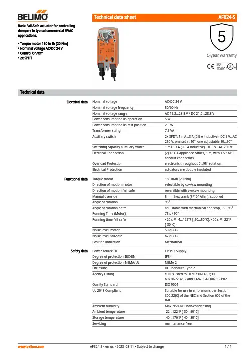
AFB24-SBasic Fail-Safe actuator for controllingdampers in typical commercial HVAC applications.• Torque motor 180 in-lb [20 Nm]• Nominal voltage AC/DC 24 V • Control On/Off • 2x SPDTTechnical dataElectrical dataNominal voltageAC/DC 24 V Nominal voltage frequency 50/60 HzNominal voltage rangeAC 19.2...28.8 V / DC 21.6...28.8 V Power consumption in operation 5 W Power consumption in rest position 2.5 W Transformer sizing 7.5 VAAuxiliary switch2x SPDT, 1 mA...3 A (0.5 A inductive), DC 5 V...AC 250 V, one set at 10°, one adjustable 10...90°Switching capacity auxiliary switch 1 mA...3 A (0.5 A inductive), DC 5 V...AC 250 V Electrical Connection (2) 18 GA appliance cables, 1 m, with 1/2" NPT conduit connectorsOverload Protection electronic throughout 0...95° rotation Electrical Protectionactuators are double insulated Functional dataTorque motor180 in-lb [20 Nm]Direction of motion motor selectable by ccw/cw mounting Direction of motion fail-safe reversible with cw/ccw mounting Manual override 5 mm hex crank (3/16" Allen), supplied Angle of rotation 95°Angle of rotation note adjustable with mechanical end stop, 35...95°Running Time (Motor)75 s / 90°Running time fail-safe <20 s @ -4...122°F [-20...50°C], <60 s @ -22°F [-30°C]Noise level, motor 50 dB(A)Noise level, fail-safe 62 dB(A)Position indicationMechanical Safety dataPower source ULClass 2 Supply Degree of protection IEC/EN IP54Degree of protection NEMA/UL NEMA 2Enclosure UL Enclosure Type 2Agency Listing cULus listed to UL60730-1A:02; UL60730-2-14:02 and CAN/CSA-E60730-1:02Quality Standard ISO 9001UL 2043 CompliantSuitable for use in air plenums per Section 300.22(C) of the NEC and Section 602 of the IMCAmbient humidity Max. 95% RH, non-condensing Ambient temperature -22...122°F [-30...50°C]Storage temperature -40...176°F [-40...80°C]Servicingmaintenance-freeAFB24-SFootnotesApplicationOperationTypical specificationWeight Weight5.6 lb [2.5 kg]MaterialsHousing material Galvanized steel and plastic housing†Rated Impulse Voltage 800V, Type of Action 1.AA.B, Control Pollution Degree 3.Product featuresFor On/Off, fail-safe control of dampers in HVAC systems. Actuator sizing should be done in accordance with the damper manufacturer's specifications. Control is On/Off from an auxiliary contact or a manual switch. The actuator is mounted directly to a damper shaft up to 1.05" in diameter by means of its universal clamp. A crank arm and several mounting brackets are available for applications where the actuator cannot be direct coupled to the damper shaft. Maximum of two AF's can be piggybacked for torque loads of up to 266 in-lbs. Minimum 3/4" diameter shaft and parallel wiring.The AF..24-S series actuators provide true spring return operation for reliable failsafe application and positive close off on air tight dampers. The spring return system provides constant torque to the damper with, and without, power applied to the actuator. The AF..24-S series provides 95° of rotation and is provided with a graduated position indicator showing 0° to 95°. The actuator may be stalled anywhere in its normal rotation without the need ofmechanical end switches. The AF..24-S versions are provided with two built-in auxiliary switches. These SPDT switches are provided for safety interfacing or signaling, for example, for fan start-up. The switching function at the fail-safe position is fixed at 10°, the other switch function is adjustable between 10° to 90°. The AF..24-S actuator is shipped at 5° (5° from full fail-safe) to provide automatic compression against damper gaskets for tight shut-off.On/Off spring return damper actuators shall be direct coupled type which require no crank arm and linkage and be capable of direct mounting to a jackshaft up to a 1.05” diameter. Theactuators must be designed so that they may be used for either clockwise or counter clockwise fail-safe operation. Actuators shall be protected from overload at all angles of rotation. If required, two SPDT auxiliary switch shall be provided having the capability of one beingadjustable. Actuators with auxiliary switches must be constructed to meet the requirements for Double Insulation so an electrical ground is not required to meet agency listings. Actuators shall be cULus listed and have a 5 year warranty, and be manufactured under ISO 9001 International Quality Control Standards. Actuators shall be as manufactured by Belimo.AccessoriesElectrical accessoriesDescriptionType Auxiliary switch, mercury-free P475Auxiliary switch, mercury-freeP475-1Signal simulator, Power supply AC 120 V PS-100Cable conduit connector 1/2"TF-CC US Transformer, AC 120 V to AC 24 V, 40 VAZG-X40AFB24-SMechanical accessoriesDescriptionTypeAnti-rotation bracket, for AF / NFAF-P Shaft extension 240 mm ø20 mm for damper shaft ø8...22.7 mm AV8-25End stop indicatorIND-AFB Shaft clamp reversible, for central mounting, for damper shafts ø12.7 / 19.0 / 25.4 mmK7-2Ball joint suitable for damper crank arm KH8 / KH10KG10A Ball joint suitable for damper crank arm KH8KG8Damper crank arm Slot width 8.2 mm, clamping range ø14...25 mm KH10Damper crank arm Slot width 8.2 mm, for ø1.05"KH12Damper crank arm Slot width 8.2 mm, clamping range ø10...18 mmKH8Actuator arm, for 3/4" shafts, clamping range ø10...22 mm, Slot width 8.2 mmKH-AFB Push rod for KG10A ball joint 36” L, 3/8” diameterSH10Push rod for KG6 & KG8 ball joints (36” L, 5/16” diameter).SH8Wrench 0.32 in and 0.39 in [8 mm and 10 mm]TOOL-06Retrofit clipZ-AF Mounting bracket for AF..ZG-100Mounting bracketZG-101Dual actuator mounting bracket.ZG-102Mounting bracket ZG-109Linkage kitZG-110Mounting bracket for AF / NFZG-118Jackshaft mounting bracket.ZG-120Mounting kit for linkage operation for flat and side installation ZG-AFB Mounting kit for foot mount installation ZG-AFB118Damper clip for damper blade, 3.5” width.ZG-DC1Damper clip for damper blade, 6” width.ZG-DC21" diameter jackshaft adaptor (11" L).ZG-JSA-11-5/16" diameter jackshaft adaptor (12" L).ZG-JSA-21.05" diameter jackshaft adaptor (12" L).ZG-JSA-3Weather shield 13x8x6" [330x203x152 mm] (LxWxH)ZS-100Baseplate, for ZS-100ZS-101Weather shield 406x213x102 mm [16x8-3/8x4"] (LxWxH)ZS-150Explosion proof housing 16x10x6.435" [406x254x164 mm] (LxWxH), UL and CSA, Class I, Zone 1&2, Groups B, C, D, (NEMA 7), Class III, Hazardous (classified) LocationsZS-260Weather shield 17-1/4x8-3/4x5-1/2" [438x222x140 mm] (LxWxH), NEMA 4X, with mounting bracketsZS-300Weather shield 17-1/4x8-3/4x5-1/2" [438x222x140 mm] (LxWxH), NEMA 4X, with mounting brackets ZS-300-5Shaft extension 1/2"ZS-300-C1Shaft extension 3/4"ZS-300-C2Shaft extension 1"ZS-300-C3Baseplate extension Z-SF Linkage kitJackshaft Retrofit Linkage with Belimo Rotary ActuatorsZG-JSLElectrical installationWarning! Live electrical components!During installation, testing, servicing and troubleshooting of this product, it may be necessary to work with live electrical components. Have a qualified licensed electrician or other individual who has been properly trained in handling live electrical components perform these tasks. Failure to follow all electrical safety precautions when exposed to live electrical componentscould result in death or serious injury.Meets cULus requirements without the need of an electrical ground connection.Apply only AC line voltage or only UL-Class 2 voltage to the terminals of auxiliary switches.Mixed or combined operation of line voltage/safety extra low voltage is not allowed.Actuators with appliance cables are numbered.Provide overload protection and disconnect as required.AFB24-SActuators may also be powered by DC 24 V.Two built-in auxiliary switches (2x SPDT), for end position indication, interlock control, fanstartup, etc.Actuators may be powered in parallel. Power consumption must be observed.Parallel wiring required for piggy-back applications.Wiring diagramsOn/Off Auxiliary SwitchesDimensions。
1.系统描述...................................................................................................................................- 3 -1.1系统布局图.......................................................................................................................................................- 4 -1.2基本原理...........................................................................................................................................................- 5 -1.3设备说明...........................................................................................................................................................- 6 -1.3.1电动缸DEMxB...........................................................................................................................................- 6 -1.3.2接线盒和电缆..........................................................................................................................................- 8 -1.3.3ACV9BR伺服驱动器...............................................................................................................................- 10 -2.技术规格....................................................................................................................................- 16 -2.1电动缸特性.....................................................................................................................................................- 16 -2.2伺服驱动器的技术特性.................................................................................................................................- 18 -2.3附属设备的技术规格.....................................................................................................................................- 20 -2.3.1主电源变压器........................................................................................................................................- 20 -2.3.2再生电阻RRC.........................................................................................................................................- 20 -2.3.3外部过滤器EFBR...................................................................................................................................- 21 -3.安装和接线.............................................................................................................................- 22 -3.1电动缸在塞棒机构上的安装.........................................................................................................................- 22 -3.1.1塞棒机构的准备....................................................................................................................................- 22 -3.1.1.1 塞棒机构固定件的图纸.....................................................................................................................- 22 -3.1.1.2 DEM电动缸在塞棒机构上的正确安装..............................................................................................- 23 -3.1.1.3塞棒机构间隙和阻力的检查..............................................................................................................- 24 -3.1.2电动缸的安装........................................................................................................................................- 26 -3.1.3塞棒的安装............................................................................................................................................- 27 -3.1.4隔热保护................................................................................................................................................- 28 -3.2.1接线盒JB9BR的安装说明.....................................................................................................................- 30 -3.2.2电缆说明................................................................................................................................................- 30 -3.2.3接线推荐规范和CE标准.......................................................................................................................- 32 -3.2.3.1 屏蔽线的接地.....................................................................................................................................- 32 -3.2.3.2 内部金属导体之间的连接.................................................................................................................- 32 -3.2.3.3 接线盒内的电缆连接.........................................................................................................................- 33 -3.2.3.4 驱动器侧的电缆连接.........................................................................................................................- 34 -3.2.4热区电缆的连接....................................................................................................................................- 35 -3.3驱动器ACV9BR的安装和接线.......................................................................................................................- 36 -3.3.1尺寸........................................................................................................................................................- 36 -3.3.2安装、定位和冷却................................................................................................................................- 37 -3.3.3电源的连接............................................................................................................................................- 39 -4.操作........................................................................................................................................- 40 -4.1手动模式.........................................................................................................................................................- 40 -4.2远程工作模式.................................................................................................................................................- 41 -4.3自动模式.........................................................................................................................................................- 41 -4.4塞棒关闭和安全装置.....................................................................................................................................- 42 -4.4.1塞棒关闭................................................................................................................................................- 42 -4.4.2断开电机电源(可选项).....................................................................................................................- 42 -4.5运行故障的处理.............................................................................................................................................- 43 -5.维护........................................................................................................................................- 44 -5.1检查周期.........................................................................................................................................................- 44 -5.2电动缸的检查和维护.....................................................................................................................................- 45 -5.3推荐的备件.....................................................................................................................................................- 49 -5.4伺服驱动器的故障代码.................................................................................................................................- 53 -5.5故障的数字输出代码.....................................................................................................................................- 57 -5.6驱动器复位和状态显示.................................................................................................................................- 58 -5.7没有报警显示时的故障排除.........................................................................................................................- 59 -6.辅助设备.................................................................................................................................- 61 -6.1DEM系列电动缸的测试台..............................................................................................................................- 61 -6.2塞棒机构MQS..................................................................................................................................................- 61 -1.系统描述SERT的塞棒执行器系统用于控制塞棒和塞棒机构的位置,以控制流入结晶器的钢水的流量。
前 言感谢您信任并选用深圳市山龙电控设备有限公司生产的SLSDA系列交流伺服驱动器。
本系列交流伺服驱动器是我公司自主研发并具有自主知识产权的全数字通用型交流伺服系统,具有高智能化、小体积、高精度、高可靠性等特点。
为了使本伺服驱动器能够更稳定可靠地工作,确保使用者的安全,请在使用本产品之前仔细阅读本使用说明书。
阅读完后请妥善保管此说明书,以备随时查阅。
目录目录.....................................................................................................................- 1 -第1章产品规格.............................................................................................- 2 -第2章产品外观、连接端子分布图.............................................................- 3 -2.1伺服驱动器的产品外观图.............................................................- 3 -2.2伺服驱动器的产品外形尺寸图.....................................................- 4 -2.3三相交流永磁同步伺服电机外形尺寸图.....................................- 4 - 第3章面板操作与试运行.............................................................................- 5 -3.1 面板说明........................................................................................- 5 -3.2 各种模式的切换............................................................................- 6 -3.3 监视模式........................................................................................- 6 -3.4 参数设置........................................................................................- 8 -3.5 参数管理........................................................................................- 8 -3.6 简单试运行..................................................................................- 10 -3.6.1速度试运行........................................................................- 10 -3.6.2 JOG点动运行...................................................................- 11 - 第4章应用实例...........................................................................................- 13 -4.1 山龙刺绣机主轴使用实例..........................................................- 13 -4.1.1山龙刺绣机主轴使用接线................................................- 13 -4.1.2山龙刺绣机主轴使用操作方法........................................- 14 -4.1.3驱动器参数设置详细说明................................................- 16 -4.2 山龙刺绣机绣框X/Y使用实例.................................................- 17 -4.2.1山龙刺绣机绣框X/Y使用接线.......................................- 18 -4.2.2山龙刺绣机绣框X/Y操作方法.......................................- 19 -4.2.3驱动器参数设置详细说明................................................- 21 -4.2.4绣框X/Y驱动器相关参数调整说明...............................- 22 -- 1 -- 2 -输入电源 三相或单相AC220V -15~+10% 50/60Hz 温度工作:0~40°C 存贮:-40°C ~50°C使用环境 湿度 40%~80%(无结露) 控制方法 ①位置控制 ②速度控制 ③转矩控制 ④JOG 运行 ⑤试运行控制再生制动内置单相或三相速度频率响应 200Hz 或更高 速度波动率 <±0.03(负载0~100%)<±0.02(电源-15~+10%)(数值对应于额定速度)调速比 1:30000 特性脉冲频率≤500kHz 显示 6位数码管 界面操作按键×4控制输入①伺服使能 ②报警清除 ③CCW 驱动禁止 ④CW 驱动禁止 ⑤偏差计数器清零/速度选择1/零速箝位 ⑥指令脉冲禁止/速度选择2 ⑦CCW 转矩限制 ⑧CW 转矩限制 控制输出①伺服准备好输出 ②伺服报警输出 ③定位完成输出/速度到达输出 ④机械制动器释放输入方式①脉冲+方向 ②CCW 脉冲/CW 脉冲 ③两相A/B 正交脉冲电子齿轮 1/32767~32767 位置控制反馈脉冲 2500线/转、混合式增量编码器速度控制 4种内部速度加减速功能参数设置 1~10000ms / 1000r/min监视功能转速、当前位置、指令脉冲积累、位置偏差、电机转矩、电机电流、直线速度、转子绝对位置、指令脉冲频率、运行状态、输入输出端子信号等保护功能超速、主电源过压欠压、过流、过载、制动异常、编码器异常、控制电源异常、位置超差等2.1 伺服驱动器的产品外观图- 3 -2.3 三相交流永磁同步伺服电机外形尺寸图- 4 -3.1 面板说明操作面板(如图3-1 操作面板)由6个LED数码管和4个按键▲、▼、◀、Enter及两个状态指示灯组成。
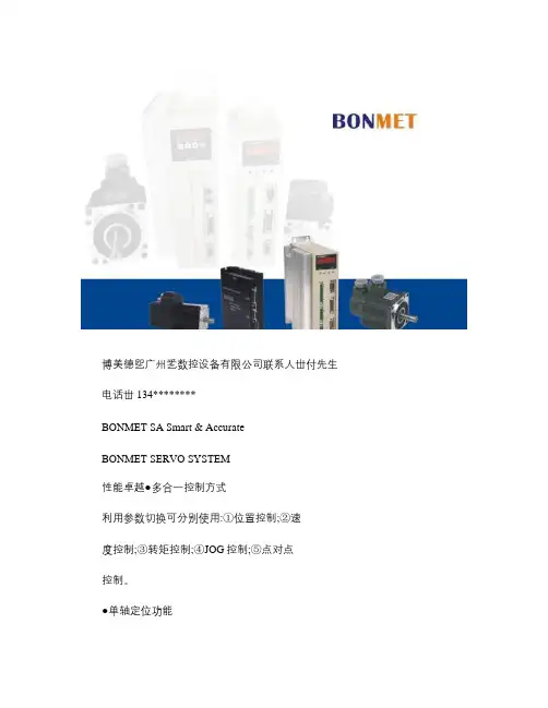
前言感谢您购买并使用BONMET伺服驱动器,本使用说明书将主要为您介绍以下内容:●伺服驱动器的组成说明●伺服驱动器的安装与检查●伺服驱动器的所有参数说明●伺服驱动器的控制功能以及调整方法●故障处理方法●检测与维护在使用前,谨请认真阅读本使用说明书,同时,请您在熟读本产品安全注意事项的基础上使用。
此外,请将它妥善放置在安全的地方以便随时查阅。
如果您在使用上仍有问题,请咨询本公司客服中心寻求技术支持。
安全注意事项●防止触电危险·接线或检测之前,请确认电源处于OFF状态。
●防止火灾注意·不要将伺服驱动器、伺服电机以及制动电阻安放在易燃物质上或靠近易燃物质。
●接线注意·请确认交流主回路电源的电压与驱动器器的额定电压是否一致。
●运行和调试注意·散热片及制动电阻因高温请勿触摸。
●其他注意第一章型号与规格1.1产品确认产品到货后,为了防止本产品在购买与配送过程中的疏忽,请就以下项目进行确认。
●到货产品是否与您订购的产品型号一致:参阅下节的型号说明,分別检查伺服电机与伺服驱动器上铭牌上的产品型号。
●伺服电机的旋转轴是否运行顺利:能用手轻轻转动则属正常,但是带失电制动器的电机则无法用手拧动电机轴。
●是否有损坏的地方:请察看外观,检查有无因运输而造成的损伤。
如有任何上述情况发生,请与厂家或者代理商联系。
1.2铭牌与型号说明1.2.1伺服电机●铭牌说明图1-1 伺服电机铭牌说明●型号说明图1-2伺服电机型号说明1.2.2 交流伺服驱动器 ● 铭牌说明图1-3 交流伺服驱动器铭牌说明● 型号说明图1-4交流伺服驱动器型号说明1.3 产品简介 1.3.1 伺服电机● 直插式连线旋转伺服电机(42系列,60系列,80系列)图1-5直插式连线旋转伺服电机各部分名称●旋钮式连线旋转伺服电机(110系列,130系列,150系列)图1-6 旋钮式连线旋转伺服电机各部分名称●正转(CCW)反转(CW)博美德伺服电机运转方向定义为:面对电机轴,CCW(逆时针)方向为正方向,CW(顺时针)方向为反方向。
SMD-30/30-XS硬体操作说明书匯出日期:2023-05-10修改日期:2021-04-192023/05/10, 21:101 序言感谢您长期对本公司产品的使用与支持。
本公司伺服团队不断致力於各项产品的研发,期许本公司产品与服务能给使用者带来最大的效益。
新代高性能驱动器系列产品为本公司最新推出之伺服驱动器,本产品使用高品质之元件与材料,并经过严格测试,采用精密向量控制,具有高精确度、高稳定性、高效率之特性。
本使用说明内容包括驱动器的硬体规格、安装、配线与讯号,能提供给使用者最正确的指引与操作,为充分发挥产品应有的优异性能与维护人员及设备的安全,在使用前请详细阅读本使用手册,并且妥善保存,以备日後调校与保养时使用,若有任何疑虑,请与本公司联络,本公司专业人员将竭诚为您服务。
2 适用机型本单轴操作手册适用於新代SMD-30/30-XS 驱动器。
3 硬体规格3.1 说明每部驱动器在出厂前均经过详细品管检查与防撞包装处理,请使用者收到产品後应先检查外观有无撞击损伤,并将外盒与产品上之序号做比对是否一致,若有不符,请第一时间与本公司联络。
型号说明3.2 外观介绍SMD-30/30-XS驱动器功能模塊說明A M3串行通讯端口连接上位控制器与下一站驱动器,串行通讯100MbpsB Mini USB端口连接个人计算机C I/O讯号端口外接电池端口连接I/O设备(急停、警示灯…等)连接绝对型编码器供电用电池D STO讯号端口STO接口,2组安全输入,1组安全功能回授E编码器回授由上至下分别为第一与第二埠。
第一端口与第二端口为连接马达编码器。
F外供电源连接三相交流电200V~230V(RST)G控制电源若有安规需求,可将控制电源自L1,L2独立供电,连接单相交流电200~230V,输入电压规格需与RST相同。
H回生电阻两种接法,择一使用即可:1. 外部回生电阻连结至P、B22. 内建煞车为将B1、B2短路I电机电源供给连接马达侧提供马达电源(UVW)J记忆用电池提供绝对式编码器记忆功能所需之电源3.3 外形尺寸3.4 驱动器规格新代驱动器SMD-30/30-XS电源额定电源电压三相200~230V 50/60Hz电源电压容许-15 ~ +10%范围电源频率变动±5%范围输出额定输出电流7.6A x 2过电流能力150% 60s、200% 1s控制方式三相全波整流,SVPWM-VVVF控制回生电阻内建、可外接外接,请参考回生电阻选用章节回授编码器支援串列介面:Tamagawa、SYNNET、NIKON、FeeDAT选配扩充编码器模组:支援Tamagawa、SYNNET、NIKON、ABZ、串列、SSI、BiSS (不支援UVW省配线型编码器)(若要使用扩充编码器模组,请参考伺服10PX1/10PX3扩充模组操作文件) PC通讯介面MINI-USB控制器串列通Mechatrolink III讯介面输出入信号数位输入4点,可规划数位输出2点,可规划STO双通道安全扭矩停止开关(2I 1O)冷却方式风扇冷却环境温度0℃ ~ 55℃(若环境温度超过45℃以上时,请强制周边空气循环)、储存:-20~65℃ (非冻结)湿度最大90% RH (非结露)、储存:90%RH以下 (非结露)安装地点室内(避免阳光直射);无腐蚀性气体、易燃性气体、油雾或尘埃海拔1000公尺以下至海平面振动最大 5.9 m/s2重量 3.9 kg•••••••••••••••••••••4 搬运与安装4.1 搬运搬运时必须拿取驱动器的机身,不能只拿取上盖或其中部分,否则可能造成掉落的危险。
交流伺服驱动器使用手册目录第一章概述1.1产品介绍 (1)1.2产品外观 (2)1.3与安全有关的符号说明 (3)1.4警告标志的内容 (4)1.5安全注意事项 (4)1.6到货检查 (7)第二章产品规格2.1 驱动器规格 (8)2.2电机规格 (9)2.3隔离变压器 (14)第三章安装3.1 环境条件 (15)3.2 伺服驱动器安装 (16)3.3伺服电机安装 (18)第四章接线4.1标准接线 (20)4.2端子功能 (22)4.3 I/O 接口原理 (26)4.4 伺服电机接线 (29)第五章显示与操作5.1键盘操作 (31)5.2. 监视方式 (32)5.3 参数设置 (35)5.4 参数管理 (36)5.5 速度试运行.................................................................. .39 5.6 JOG运行.. (39)5.7电机测试 (40)5.8 其它 (40)目录第六章通电运行6.1 电源的连接 (41)6.2 通电试运行 (43)6.3 参数调整 (45)第七章参数7.1 参数一览表 (48)7.2 参数功能 (50)第八章报警与处理8.1 报警一览表 (59)8.2 报警处理方法 (60)第九章常见问题9.1 常见问题报警.............................................................. ..67 9.2 频繁出现Err-15、Err-30、Err-31、Err-32报警.. (67)9.3 型号代码参数与电机对照表 (68)交流伺服驱动器使用手册第一章概述1.1 产品简介:随着交流伺服技术的成熟稳定,产品性能不断提高,适应工业控制向高速度、高精度、高效率、数字智能化方向发展,同时随着伺服产品性价比的不断提升,伺服控制替代步进控制已成为产业发展趋势。
交流伺服技术已从军工航空航天领域广泛深入地渗透到各行各业,广泛应用于数控机床、纺织机械、轻工机械、网版印刷、包装机械、自动生产线等自动化领域。
CDS V Command SeriesMADE IN TAIWAN(一) 安裝說明.................................................P1.P2(二) 規格說明.................................................P3.P4(三) PC板零件配置圖............................................P5(四) 系統流程圖...................................................P6(五) 電源供應說明................................................P7(六) 驅動器與馬達的選配說明.................................P8(七) 速度迴授電壓規格的選配說明...........................P9(八) 信號及配線說明....................................P10~P20(九) 保護功能及狀態說明...............................P21.P22(十) 調整說明.............................................P23~P27 (十一) 選項功能說明....................................P28~P34 (十二) 運轉異常排除說明..............................P35~P36註:此說明書內容若遇有修改或增列項目時,新設內容會以增頁方式 貼於最後頁的Memo欄內,敬請留意。
謝謝您的惠顧如您所知粗糙的驅動裝置,不僅會降低系統的伺服性能,更會損傷伺服馬達卻常被忽略;因此我們嚴謹的設計了CDS系列伺服驅動器,它俱有高效率的驅動裝置及周全的系統保護功能,對於驅動品質及人、機操作安全上均能提供優異的表現,同時對於DC有刷馬達常被垢病的電刷磨耗問題;更設計許多獨到的維護措施,大幅提升電刷的維護及使用時限,在某些應用場合比起時下許多AC無刷伺服系統,常有更耐久的表現,尤其對於低轉速,高扭力及動作線性要求較高的場合,CDS系列伺服驅動器,相信是您最可靠而實惠的選擇。
Instruction ManualStep Motor Driver (24 VDC Servo) Pulse input type Series LECPA###-#The intended use of the step motor driver is to control the movement of an electrical actuator in response to step data and electrical inputs.These safety instructions are intended to prevent hazardous situations and/or equipment damage. These instructions indicate the level of potential hazard with the labels of “Caution,” “Warning” or “Danger.”They are all important notes for safety and must be followed in addition to International Standards (ISO/IEC) *1), and other safety regulations.IEC 60204-1: Safety of machinery - Electrical equipment of machines. (Part 1: General requirements)ISO 10218-1: Robots and robotic devices - Safety requirements for industrial robots - Part 1: Robots.• Refer to product catalogue, Operation Manual and Handling Precautions for SMC Products for additional information. • Keep this manual in a safe place for future reference.CautionCaution indicates a hazard with a low level of risk which, if not avoided, could result in minor or moderate injury.WarningWarning indicates a hazard with a medium level of riskwhich, if not avoided, could result in death or serious injury.DangerDanger indicates a hazard with a high level of risk which, ifnot avoided, will result in death or serious injury.Warning• Always ensure compliance with relevant safety laws and standards.• All work must be carried out in a safe manner by a qualified person in compliance with applicable national regulations.2.1General specificationsItemSpecificationsCompatible motorStep motor (servo 24 VDC)Power supply voltage24 VDC +/-10%(motor drive control, stop, lock brake release).Current consumption 3 A (Peak 5 A) maximum Parallel Inputs 5 inputs (photo-coupler isolation) Parallel Outputs 9 outputs (photo-coupler isolation)Compatible encoderIncremental A/B phase(resolution: 800 pulses / rotation)Serial communication RS485Lock controlForced lock release terminal (applicable tonon-magnetizing lock). Cable lengthIO cable: 5 m maximumActuator cable: 20 m maximumCooling method Natural air-cooling Operatingtemperature0o C to 40o C (no freezing)Storage temperature -10o C to 60o C (no freezing) Operating humidity 90% RH or less (no condensation)Insulation resistance50 MΩ (500 VDC)between external terminals and caseWeight120 g (Direct mounting type)140 g (DIN rail mounting type)WarningSpecial products (-X) might have specifications different from those shown in this section. Contact SMC for specific drawings.4 Installation4.1 InstallationWarning• Do not install the product unless the safety instructions have been read and understood.• Design the installation so that the temperature surrounding the controller is within the specified operating temperature. Leave enough space between the controllers so that the operating temperature of the controllers remains within the specification range.• Mount the controller vertically with 30 mm minimum space on the top and bottom of the controller as shown below.• Allow 60 mm minimum space between the front of the controller and a door (lid) so that the connectors can be connected and disconnected.4.2 Mounting• The controller can be direct mounted using screws or mounted on a DIN rail (model LECPA##D).• When using DIN rail mounting, hook the controller on the DIN rail and press the lever down to lock it.CautionIf the mounting surface for the controller is not flat or is uneven, excessive stress may be applied to the enclosure, which can cause failure. Be sure to mount on a flat surface. 4.3 EnvironmentWarning• Do not use in an environment where corrosive gases, chemicals, salt water or steam are present.• Do not use in an explosive atmosphere.• Do not expose to direct sunlight. Use a suitable protective cover.• Do not install in a location subject to vibration or impact in excess of the product’s specifications.• Do not mount in a location exposed to radiant heat that would result in temperatures in excess of the product’s specifications.• Avoid mounting the controller near a vibration source, such as a large electromagnetic contactor or circuit breaker on the same panel. • Do not use in an environment with strong magnetic fields present. 4.4 WiringCaution• Do not perform wiring while the power is on. • Confirm proper insulation of wiring.• Do not route wires and cables together with power or high voltage cables.• Keep wiring as short as possible to prevent interference from electromagnetic noise and surge voltage.• Do not use an inrush current limited type of power supply for the controller.• Do not connect multiple wires to one connector terminal.Power Supply ConnectorWire the power supply cable to the power supply plug connector, then insert it into connector PWR on the driver.• Use special screwdriver (Phoenix Contact No. SZS0.4×2.0) to open / close lever and insert the wire into the connector terminal.Power Supply Wire specificationsPrepare the wiring according to the following specifications (to be prepared by the user).ORIGINAL INSTRUCTIONSPower supply connector. SMC Part No. LEC-D-1-1. Phoenix Contact Part No: FK-MC0.5/5-ST-2.510 mm minimum Driver30 mm min. (Direct mounting) 50 mm min. (DIN rail mounting)30 mm minimumParallel I/O Connector• When connecting the parallel I/O connector to a PLC use an SMC parallel I/O cable (LEC-CL5-#).• There are 2 types of parallel I/O with this controller: NPN type and PNP type. Check the polarity required before use.The parallel I/O wiring should be prepared according to the polarity.For further details of the Parallel I/O wiring refer to the Operation Manual on the SMC website (URL: https:// ).4.5 Ground connection• Place a ground cable with crimped terminal under one of the M4 mounting screws with a shakeproof washer and tighten the screw.CautionThe M4 screw, cable with crimped terminal and shakeproof washer must be prepared by the user.The controller must be connected to Ground to reduce noise. If higher noise resistance is required, ground the 0 V (signal ground). When grounding the 0 V, avoid flowing noise from ground to 0 V.• A dedicated Ground connection must be used. Grounding should be to a D-class ground (ground resistance of 100 Ω maximum).• The cross-sectional area of the ground cable shall be 2 mm 2 minimum. • The Grounding point should be as near as possible to the controller. Keep the grounding cable as short as possible.In order to move the electric actuator to a specific position, it is necessary to set up the patterns of operation with a PC using the controller setting software or by using a teaching box. This set up data will be recorded in the memory of the controller.Step data describes the data that sets items of operation (such as positioning width) excluding speed, position, acceleration, and deceleration, which are determined by the pulse-signal input. Step data will become effective as soon as it is recorded into the driver.Refer to the Operation Manual on the SMC website (URL: https:// ) for further setting details.Refer to the table below for details of the LED status.LEDDescriptionPWROFFPower is not supplied Green LED is ON Power is suppliedGreen LED is flashingEEPROM memory writing ALM OFFNormal operationRed LED is ONController Alarm generated7 How to OrderRefer to the catalogue on the SMC website (URL: https:// ) for the How to Order information.8 Outline Dimensions (mm)Refer to the drawings / operation manual on the SMC website (URL: https:// ) for outline dimensions.9 Maintenance9.1 General MaintenanceCaution• Not following proper maintenance procedures could cause the product to malfunction and lead to equipment damage.• Before performing maintenance, turn off the power supply. Check the voltage with a tester 5 minutes after the power supply is turned OFF. • If any electrical connections are disturbed during maintenance, ensure they are reconnected correctly and safety checks are carried out as required to ensure continued compliance with applicable national regulations.• Do not make any modification to the product.• Do not disassemble the product, unless required by installation or maintenance instructions.Caution• Maintenance should be performed according to the procedure indicated in the Operation Manual.• When equipment is serviced, first confirm that measures are in place to prevent dropping of work pieces and run-away of equipment, etc, then cut the power supply to the system. When machinery is restarted, check that operation is normal with actuators in the correct position.Warning• Perform maintenance checks periodically.• Confirm wiring and screws are not loose. Loose screws or wires may cause unexpected malfunction.• Conduct an appropriate functional inspection and test after completing maintenance. In case of any abnormalities (if the actuator does not move, etc.), stop the operation of the system. Otherwise, an unexpected malfunction may occur and it will become impossible to ensure safety. Operate an emergency stop instruction to confirm safety. • Do not put anything conductive or flammable inside of the controller. • Ensure sufficient space around the controller for maintenance.10 Limitations of Use10.1 Limited warranty and Disclaimer/Compliance Requirements Refer to Handling Precautions for SMC Products.11 Product disposalThis product shall not be disposed of as municipal waste. Check your local regulations and guidelines to dispose of this product correctly, in order to reduce the impact on human health and the environment.12 ContactsRefer to or www.smc.eu for your local distributor / importer.URL: https:// (Global) https://www.smc.eu (Europe) SMC Corporation, 4-14-1, Sotokanda, Chiyoda-ku, Tokyo 101-0021, Japan Specifications are subject to change without prior notice from the manufacturer. © 2021 SMC Corporation All Rights Reserved. Template DKP50047-F-085MPin No. Insulation Colour Dot mark Dot colour Category Signal 1 Light brown ● Black 24 V COM+ 2 Light brown ● Red 0 V COM- 3 Yellow ● Black Pulse signal NP+ 4 Yellow ● Red Pulse signal NP- 5 Light green ● Black Pulse signal PP+ 6 Light green ● Red Pulse signal PP- 7 Grey ● Black Input SETUP 8 Grey ● Red Input RESET 9 White ● Black Input SVON 10 White ● Red Input CLR 11 Light brown ●● Black Input TL 12 Light brown ●● Red Output TLOUT 13 Yellow ●● Black Output WAREA 14 Yellow ●● Red Output BUSY 15 Light green ●● Black Output SETON 16 Light green ●● Red Output INP 17 Grey ●● Black Output SVRE 18 Grey ●● Red Output ESTOP19White ●● Black Output ALARM 20White ●● Red Output AREA。