JYT伺服驱动说明书
- 格式:pdf
- 大小:6.12 MB
- 文档页数:59
380V 1kW 二代单轴驱动器 硬体操作说明书(SVD32C1-010)匯出日期:2023-05-11修改日期:2022-04-202023/05/11, 00:491 序言感谢您长期对本公司产品的使用与支持。
本公司伺服团队不断致力於各项产品的研发,期许本公司产品与服务能给使用者带来最大的效益。
新代高性能驱动器系列产品为本公司最新推出之伺服驱动器,本产品使用高品质之元件与材料,并经过严格测试,采用精密向量控制,具有高精确度、高稳定性、高效率之特性。
本使用说明内容包括驱动器的硬体规格、安装、配线与讯号,能提供给使用者最正确的指引与操作,为充分发挥产品应有的优异性能与维护人员及设备的安全,在使用前请详细阅读本使用手册,并且妥善保存,以备日後调校与保养时使用,若有任何疑虑,请与本公司联络,本公司专业人员将竭诚为您服务。
2 适用机型本单轴操作手册适用於新代 1kW 二代单轴驱动器。
3 硬体规格3.1 说明每部驱动器在出厂前均经过详细品管检查与防撞包装处理,请使用者收到产品後应先检查外观有无撞击损伤,并将外盒与产品上之序号做比对是否一致,若有不符,请第一时间与本公司联络。
型号说明3.2 外观介绍3.3 外形尺寸SVD32C1-010驱动器规格新代驱动器SVD32C1-010电源额定电源电压三相 380~440V 50/60Hz电源电压容许-15 ~ +10%范围电源频率变动±5%范围输出 额定输出电流 4.3A过电流能力150% 60s、200% 1s控制方式 三相全波整流输入,空间向量脉宽调变控制,可变电压可变频率(SVPWM-VVVF)输出回生电阻 建议使用内建即可,如要外接,请参考回生电阻选用章节新代驱动器SVD32C1-010反馈编码器 支援串列介面:Tamagawa、SYNNET、NIKON、FeeDAT、EnDAT、Panasonic、Mitsubishi、Mitutoyo、HCFA。


MMT-直流伺服驱动器使用手册济南科亚电子科技有限公司直流伺服驱动器使用说明书一、概述:该伺服驱动器采用全方位保护设计,具有高效率传动性能:控制精度高、线形度好、运行平稳、可靠、响应时间快、采用全隔离方式控制等特点,尤其在低转速运行下有较高的扭矩及良好的性能,在某些场合下和交流无刷伺服相比更能显示其优异的特性,并广泛应用于各种传动机械设备上。
二、产品特征:◇PWM控制H桥驱动◇四象限工作模式◇全隔离方式设计◇线形度好、控制精度高◇零点漂移极小◇转速闭环反馈电压等级可选◇标准信号接口输入0--±10V◇开关量换向功能◇零信号时马达锁定功能◇上/下限位保护功能◇使能控制功能◇上/下限速度设定◇输出电流设定功能◇具有过压、过流、过温、输出短路、马达过温、反馈异常等保护及报警功能三、主要技术参数◇控制电源电压AC:110系列:AC :110V±10%220系列:AC :220V±10%◇主电源电压AC:110系列:AC 40----110V220系列:AC50---- 220V◇输出电压DC:110系列:0—130V或其它电压可设定220系列:0—230V或其它电压可设定◇额定输出电流:DC 5A(最大输出电流10A)DC 10A(最大输出电流15A)DC 20A(最大输出电流25A)◇控制精度:0.1%◇输入给定信号:0—±10V◇测速反馈电压:7V/1000R 9.5V/1000R13.5V/1000R 20V/1000R可经由PC板内插片选定并可接受其它规格订制四、安装环境要求:◇环境温度:-5ºC ~ +50ºC◇环境湿度:相对湿度≤80RH。
(无结露)◇避免有腐蚀气体及可燃性气体环境下使用◇避免有粉尘、可导电粉沫较多的场合◇避免水、油及其他液体进入驱动器内部◇避免震动或撞击的场合使用◇避免通风不良的场合使用五、电源输入说明该驱动系统分两路电源输入:即U1、V1为主电源输入,U2、V2为控制电表1注:1、驱动器的主电源(即U1 V1)独立供电时,若电源开路时,驱动器会报警(面板上的T.F灯亮)待故障排出后,驱动器自动回复正常。
t3d伺服驱动说明书第一章:引言伺服驱动是一种控制系统,用于控制和驱动伺服电机。
本说明书将详细介绍t3d伺服驱动的功能、特点、使用方法和注意事项。
第二章:产品概述2.1 产品特点t3d伺服驱动具有以下特点:- 高精度:采用先进的控制算法,可实现高精度位置和速度控制。
- 快速响应:具备快速的响应能力,可以在短时间内完成位置和速度调整。
- 广泛适用:适用于各种机器人、自动化设备和工业控制系统。
- 稳定可靠:稳定的性能和可靠的工作保证了系统的安全和稳定运行。
2.2 产品组成t3d伺服驱动由以下几部分组成:- 控制器:负责接收和解析控制信号,并根据信号控制电机的运动。
- 电机:根据控制信号的指令,进行位置和速度调整。
- 传感器:用于检测电机的位置和速度,并将信息反馈给控制器。
第三章:使用方法3.1 连接电源将t3d伺服驱动的电源线接入电源插座,并确保电源稳定。
3.2 连接控制器将控制器的输出信号线连接到t3d伺服驱动的输入端口。
确保信号连接正确,避免反接或短路。
3.3 连接电机将电机的输出轴与所需的机械装置或负载连接,确保连接牢固可靠。
3.4 设置参数根据实际应用需求,通过控制器设置相应的参数,如位置精度、速度范围等。
确保参数设置正确,以达到最佳控制效果。
3.5 启动和停止按照控制器的启动和停止指令操作,启动和停止t3d伺服驱动,实现电机的运动控制。
第四章:注意事项4.1 安全操作在使用t3d伺服驱动时,务必遵守安全操作规程,确保操作人员的人身安全。
4.2 环境要求t3d伺服驱动应在干燥、通风良好的环境中使用,避免水、尘等外部物质对设备的影响。
4.3 维护保养定期对t3d伺服驱动进行维护保养,保持设备的清洁和正常工作状态。
4.4 故障排除在使用过程中,如果发生故障或异常情况,及时进行故障排除,确保设备的正常运行。
第五章:常见问题解答5.1 为什么电机无法正常运转?可能原因有:电源故障、信号线连接错误、参数设置错误等。
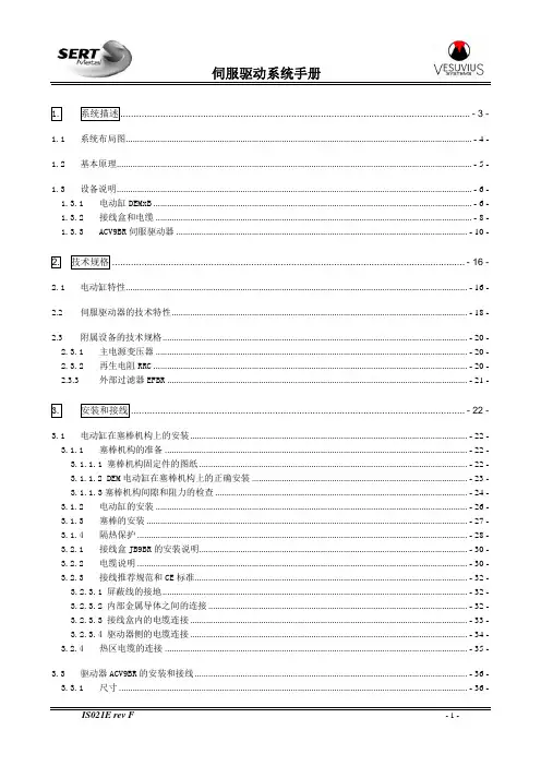
1.系统描述...................................................................................................................................- 3 -1.1系统布局图.......................................................................................................................................................- 4 -1.2基本原理...........................................................................................................................................................- 5 -1.3设备说明...........................................................................................................................................................- 6 -1.3.1电动缸DEMxB...........................................................................................................................................- 6 -1.3.2接线盒和电缆..........................................................................................................................................- 8 -1.3.3ACV9BR伺服驱动器...............................................................................................................................- 10 -2.技术规格....................................................................................................................................- 16 -2.1电动缸特性.....................................................................................................................................................- 16 -2.2伺服驱动器的技术特性.................................................................................................................................- 18 -2.3附属设备的技术规格.....................................................................................................................................- 20 -2.3.1主电源变压器........................................................................................................................................- 20 -2.3.2再生电阻RRC.........................................................................................................................................- 20 -2.3.3外部过滤器EFBR...................................................................................................................................- 21 -3.安装和接线.............................................................................................................................- 22 -3.1电动缸在塞棒机构上的安装.........................................................................................................................- 22 -3.1.1塞棒机构的准备....................................................................................................................................- 22 -3.1.1.1 塞棒机构固定件的图纸.....................................................................................................................- 22 -3.1.1.2 DEM电动缸在塞棒机构上的正确安装..............................................................................................- 23 -3.1.1.3塞棒机构间隙和阻力的检查..............................................................................................................- 24 -3.1.2电动缸的安装........................................................................................................................................- 26 -3.1.3塞棒的安装............................................................................................................................................- 27 -3.1.4隔热保护................................................................................................................................................- 28 -3.2.1接线盒JB9BR的安装说明.....................................................................................................................- 30 -3.2.2电缆说明................................................................................................................................................- 30 -3.2.3接线推荐规范和CE标准.......................................................................................................................- 32 -3.2.3.1 屏蔽线的接地.....................................................................................................................................- 32 -3.2.3.2 内部金属导体之间的连接.................................................................................................................- 32 -3.2.3.3 接线盒内的电缆连接.........................................................................................................................- 33 -3.2.3.4 驱动器侧的电缆连接.........................................................................................................................- 34 -3.2.4热区电缆的连接....................................................................................................................................- 35 -3.3驱动器ACV9BR的安装和接线.......................................................................................................................- 36 -3.3.1尺寸........................................................................................................................................................- 36 -3.3.2安装、定位和冷却................................................................................................................................- 37 -3.3.3电源的连接............................................................................................................................................- 39 -4.操作........................................................................................................................................- 40 -4.1手动模式.........................................................................................................................................................- 40 -4.2远程工作模式.................................................................................................................................................- 41 -4.3自动模式.........................................................................................................................................................- 41 -4.4塞棒关闭和安全装置.....................................................................................................................................- 42 -4.4.1塞棒关闭................................................................................................................................................- 42 -4.4.2断开电机电源(可选项).....................................................................................................................- 42 -4.5运行故障的处理.............................................................................................................................................- 43 -5.维护........................................................................................................................................- 44 -5.1检查周期.........................................................................................................................................................- 44 -5.2电动缸的检查和维护.....................................................................................................................................- 45 -5.3推荐的备件.....................................................................................................................................................- 49 -5.4伺服驱动器的故障代码.................................................................................................................................- 53 -5.5故障的数字输出代码.....................................................................................................................................- 57 -5.6驱动器复位和状态显示.................................................................................................................................- 58 -5.7没有报警显示时的故障排除.........................................................................................................................- 59 -6.辅助设备.................................................................................................................................- 61 -6.1DEM系列电动缸的测试台..............................................................................................................................- 61 -6.2塞棒机构MQS..................................................................................................................................................- 61 -1.系统描述SERT的塞棒执行器系统用于控制塞棒和塞棒机构的位置,以控制流入结晶器的钢水的流量。
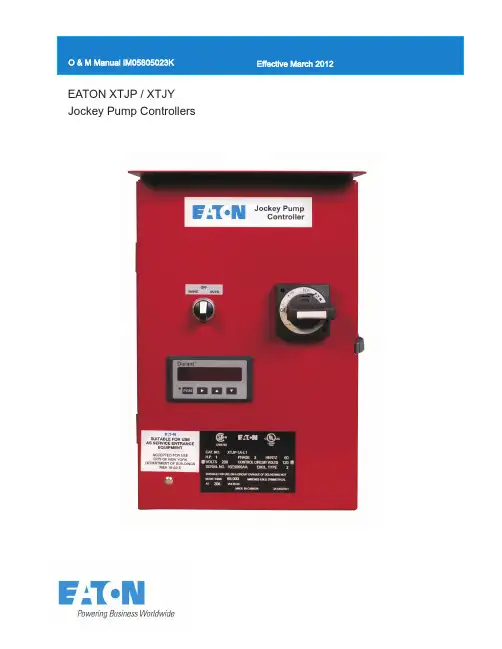
EATON XTJP / XTJY Jockey Pump ControllersDescription1.INSTALLATION AND MOUNTING OF THE CONTROLLER (3)2.SYSTEM PRESSURE CONNECTIONS (3)3.ELECTRICAL CONNECTIONS (3)3.1ELECTRICAL CHECKOUT INSTRUCTIONS (4)3.1.1 Motor Rotation Check (4)3.1.2 Starting and Stopping (4)3.1.3 Motor Circuit Protector / Overload Relay Trip Setting (4)3.1.4 Circuit Breaker Trip Settings (4)3.1.5 Run Period Timer (Optional) (4)FIGURE 1: ELECTRICAL WIRING SCHEMATIC - Three Phase (5)FIGURE 2: DIMENSIONAL DRAWING - NEMA 2 (6)FIGURE 3: ELECTRICAL WIRING SCHEMATIC - WYE DELTA (Star-Delta) (7)FIGURE 4: DIMENSIONAL DRAWING - WYE DELTA (Star-Delta) (8)4.DIGITAL DISPLAY (9)4.1PROGRAMMING...........................................................................................................9, 10, 11INSTALLATION & MAINTENANCE MANUAL FOR JOCKEY PUMP CONTROLLERSIn order to familiarize yourself with the Jockey Pump Controller, please read the instruction manual thoroughly and carefully. Retain the manual for future reference.1. Installation and Mounting of the Controller Carefully unpack the controller and inspect thoroughly.It is recommended that the controller is located as close as is practical to the motor it controlsThe controller is not free standing and must be bolted securely to a wall. For dimensional and weight data please refer to the respective data sheets for the Jockey Pump Controller.2. System Pressure ConnectionThe Jockey Pump Controller is equipped with a Pressure Transducer. The controller is provided with a ¼” NPT female system pressure connection located on the bottom, external side of the enclosure. The connection should be installed as per NFPA, pamphlet No. 20.NOTE: Water lines to the pressure transducer must be free from dirt and contamination.The pressure should not exceed what the pressure transducer is rated for.3. Electrical ConnectionsAll electrical connections should meet nationaland local electrical codes and standards.The controller should be located or so protected that they will not be damaged by water escaping from pumps or pump connections. Current carrying parts of controllers shall be a minimum of 12 inches (305 mm) above the floor level.Prior to starting verify all data on the nameplate such as, catalog number, AC line voltage and horsepower.Inspect all electrical connections, components and wiring for any visible damage and correct as necessary. Ensure that all electrical connections are tightened before energization.Install necessary conduit using proper methods and tools.Incoming AC line voltage is clearly marked L1, L2, L3 and ground, located at the top of the breaker.3.1 Electrical Checkout InstructionsWARNING :The following procedures should be carried out by a qualified electrician familiar with the electrical safety procedures associated with this product and its associated equipment..3.1.1Motor Rotation Check: With the controller energized, move the H.O.A. selector switch to "HAND" then back to “OFF” immediately to check the direction of the motor and pump rotation. If rotation direction is not correct, open the breaker and reverse the phase sequence of the load terminals of the contactor T1, T2, T3 or at the motor terminals.3.1.2Starting and Stopping: Energize the controller. With the H.O.A. selector switch set to “AUTO”, if the system water pressure is lower than the pressure transducer set-point pressure (1Lo), the pump will start. The pump will stop when pressure is above the stop point (1Lo+HYS). If the optional running period timer is included, the pump will run for the set time and then stop, provided the pressure is above the pressure stop point(1Lo+HYS). For manual operation, set the H.O.A. selector switch to “HAND' to start the pump and “OFF” to stop.3.1.3Motor Circuit Protector / Overload Relay Trip Setting: The trip setting should be set to match the motor nameplate full load amps.3.1.4Circuit Breaker Trip Settings: When a Circuit Breaker is installed, the trip setting must be set as indicated on the chart on the inside of the controller.3.1.5Run Period Timer: (Optional) Adjust the RPT dial to the desired run period time setting. Three rotary adjustment dials are provided on the front of the timer.(Ws)Single Shot - leading edge with control inputThe supply voltage U must be constantly applied to the device (green LED U/t illuminated).When the control contact S is closed, the output relay R switches into on-postion (green LED U/t illuminated) and the set interval begins (green LED U/t flashes). After the interval has expired (green LED U/tilluminated) the output relay switches into off-postion (yellow LED not illuminated).During the interval, the control contact can be operated any number of times.A further cycle can only be started when the cycle run has been completed.Adjustment Range Factory Default = 1Time RangeFactory Default = 10 mFunctionFactory Default = WsRun Period Timer Factory DefaultsFigure 1: Electrical Wiring Schematic - Three PhaseFigure 2: Standard Enclosure - Type NEMA 2N. Y. C.APPROVEDFigure 3: Electrical Wiring Schematic - Wye Delta (Star-Delta)Figure 4: Standard Enclosure - Wye Delta (Star-Delta)N. Y. C.APPROVED4. Digital DisplayThe XTJP and XTJY Jockey Pump Controllers are supplied standard with a digital panel meter that indicates the current pressure and Stop and Start pressure set points.LED DisplayHigh Visibility Red Superbright LEDFour full digits0.56in (14mm) high charactersFlashing AlarmsRatingsNEMA 4X1/8 DIN4.1 ProgrammingEnsure the Rotary Disconnect switch and the Hand-Off-Auto selector switch are in the OFF position.Apply power to the Jockey Pump Controller.Once power is applied, turn the Rotary Disconnect switch to the ON position.NOTE: The instructions below are based on the factory default settings. Displayed values may vary depending on the programmed parameter setpoint values. Factory default settings for each parameter are listed in Table 1.4.1.1 Intial SetupThe Digital Display will show the current system pressure.Press and hold the PGM button.The display will show “run”4.1.2 INPUT: (4.20)While holding the PGM button, press the UP Arrow button.The display will show “inP”Release the PGM buttonThe display is factory set to “4.20”.If the display does not show “4.20”, push the RIGHT Arrow button until “4.20” is displayedXXXrunPGMCurrent System PressurePGM+inp4.204.204.1.3 DECIMAL POINT: (1000)While holding the PGM button, press the UP Arrow button.The display will show “dp”Release the PGM buttonThe display will show “1000”Do not change the setting.4.1.4 OFFSET Minimum Transducer Pressure: (0 psi)While holding the PGM button, press the UP Arrow button.The display will show “OF”Release the PGM buttonThe display will show “+0000” – note: the “+” flashesDo not change the setting.4.1.5 FULL SCALE VALUE Maximum Transducer Pressure: (500 psi) While holding the PGM button, press the UP Arrow button.The display will show “FS”Release the UP Arrow and PGM buttonsThe display will show “+0500” – note: the “+” flashesDo not change the setting.4.1.6 RELAY 1 – Hi ALARM SETPOINT: (+9999)While holding the PGM button, press the UP Arrow button.The display will show “1Hi”Release the UP Arrow and PGM buttonsThe display will show “+9999”Do not change the setting.4.1.7 RELAY 1 – Lo ALARM SETPOINT: (+0500) Pressure Start Point While holding the PGM button, press the UP Arrow button.The display will show “1Lo”Release the UP Arrow and PGM buttonsThe display will show “+0500”Push the RIGHT Arrow button to move the value setting positionSet the desired START Point value using the UP and Down Arrow buttons (eg: For 100psi, the display will show “+0100”)4.1.8 RELAY 2 – Hi ALARM SETPOINTWhile holding the PGM button, press the UP Arrow button.The display will show “2Hi”Release the UP Arrow and PGM buttonsThe display will show “+9999”Do not change the setting.PGM+dp1000 +0000 +0500+0500 +9999 PGMPGM+ PGM+ PGM+OFFS1Lo1Hi PGM+2Hi +9999 4.1.9 RELAY 2 – Low ALARM SETPOINTWhile holding the PGM button, press the UP Arrow button.The display will show “2Lo”Release the UP Arrow and PGM buttons The display will show “-9999”Do not change the setting.4.1.10 HYSTERESIS (Differential)While holding the PGM button, press the UP Arrow button.The display will show “HYS”Release the UP Arrow and PGM buttonsThe display will show “+0000” - note: one of the “0” flashesPush the RIGHT Arrow button to move the value setting positionSet the desired Differential value using the UP and Down Arrow buttons (eg: Start Setpoint = +0100psi and the desired Stop Setpoint is 115 psi Set the HYS (differential) to +0015).Note: The minimum differential setting is 1psi (+0001).4.1.11 RUNWhile holding the PGM button, press the UP Arrow button.The display will show “run”Release the UP Arrow and PGM buttons The current pressure is displayed.PGM+PGM+PGM+2Lo HYS run -9999+0000EATON CORPORATION Page 11XXXCurrent System PressureTable 1. Parameter Default SettingsThis information booklet is published solely forinformation purposes and should not be considered all-inclusive. If further information is required, you should consult EATON.Sale of product shown in this literature is subject to terms and conditions outlined in appropriate EATON selling polices or other contractual agreement between the parties. This literature is not intended to and does not enlarge or add to any such contract. The sole source governing the rights and remedies of any purchaser of this equipment is the contract between the purchaser and EATON.NO WARRANTIES, EXPRESSED OR IMPLIED, INCLUDING WARRANTIES OF FITNESS FOR A PARTICULAR PURPOSE OR MERCHANTABILITY , OR WARRANTIES ARISING FROM COURSE OF DEALING OR USAGE OF TRADE, ARE MADE REGARDING THE INFORMATION,RECOMMENDATIONS AND DESCRIPTIONS CONTAINED HEREIN. In no event will EATON be responsible to the purchaser or user in contract, in tort (including negligence), strict liability or otherwise for any special, indirect, incidental or consequentialdamage or loss whatsoever, including but not limited to damage or loss of use of equipment, plant or power system, cost of capital, loss of power, additional expenses in the use of existing power facilities, orclaims against the purchaser or user by its information, recommendations and description contained herein.Eaton Corporation10725 - 25th Street NE Unit 124, Alberta, Canada T Tel: +1-403-717-2000Fax: +1-403-717-0567email:*********************Calgary 3N 0A4© 2012 Eaton Corporation All Rights Reserved Printed in CanadaPublication No.: IM05805023K March 2012。
金宝佳伺服驱动器说明书【实用版】目录1.金宝佳伺服驱动器说明书概述2.金宝佳伺服驱动器的主要特点3.金宝佳伺服驱动器的安装与连接4.金宝佳伺服驱动器的使用方法5.金宝佳伺服驱动器的维护与保养6.金宝佳伺服驱动器的故障排除与注意事项正文一、金宝佳伺服驱动器说明书概述金宝佳伺服驱动器是一种高性能的伺服控制系统,广泛应用于各种工业自动化设备中,如数控机床、机器人、自动化生产线等。
本文档将为您提供关于金宝佳伺服驱动器的详细使用说明,帮助您充分发挥设备的性能优势,提高生产效率。
二、金宝佳伺服驱动器的主要特点1.高精度:金宝佳伺服驱动器具有较高的角分辨率和位置控制精度,能够满足各类精密加工需求。
2.高速响应:驱动器响应速度快,能够实现高速、高加速度的运动控制。
3.良好的低速性能:金宝佳伺服驱动器在低速运行时具有优越的性能,可满足微小位移、微细加工等要求。
4.强大的过载能力:驱动器具备较强的过载能力,可在短时间内承受较大的负载冲击。
三、金宝佳伺服驱动器的安装与连接1.安装:根据设备制造商提供的安装指南进行安装,确保驱动器与电机、控制器等其他部件正确连接。
2.连接:连接驱动器的电源、控制信号、反馈信号等接口,并根据接线图进行正确接线。
四、金宝佳伺服驱动器的使用方法1.调试:在使用前,需对驱动器进行参数设置和调试,确保设备能够正常运行。
2.运行:根据设备需求,通过控制器发送指令,实现驱动器的启动、停止、加速、减速等操作。
3.调整:在运行过程中,可根据实际需求对驱动器的参数进行实时调整,以达到最佳性能。
五、金宝佳伺服驱动器的维护与保养1.定期检查:对驱动器进行定期检查,发现异常现象及时处理,确保设备正常运行。
2.清洁保养:保持驱动器及周边环境的清洁,避免灰尘、油污等进入设备内部。
3.更换零部件:根据使用情况,定期更换磨损严重的零部件,以延长设备使用寿命。
六、金宝佳伺服驱动器的故障排除与注意事项1.故障排除:遇到设备故障时,可通过查看驱动器故障代码、分析故障现象等方法进行排除。
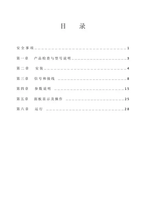
目录安全事项 (1)第一章产品检查与型号说明 (3)第二章安装 (4)第三章信号和接线 (8)第四章参数说明 (15)第五章面板显示及操作 (25)第六章运行 (28)安全事项欢迎您使用杭州之山科技有限公司生产的纺机专用伺服控制系统。
在产品存放、安装、配线、运行、检查或维修前,用户必需熟悉并遵守以下重要事项,以确保安全地使用本产品。
错误操作可能会引起危险并导致人身伤亡。
错误操作可能会引起危险,导致人身伤害,并可能使设备损坏。
严格禁止行为,否则会导致设备损坏或不能使用。
1、使用场合● 禁止将产品暴露在有水气、腐蚀性气体、可燃性气体的场合使用。
否则会导致触电或火灾。
● 禁止将产品用于阳光直射,灰尘、盐分及金属粉露末较多的场所。
● 禁止将产品用于有水、油及药品滴落的场所。
2、配线● 请将接地端子可靠接地,接地不良可能会造成触电或火灾。
● 请勿将220V驱动器电源接入380V电源,否则会造成设备损坏及触电或火灾。
● 请勿将U、V、W电机输出端子连接到三相电源,否则会造成人员伤亡或火灾。
● 必须将U、V、W电机输出端子和电机接线端子U、V、W一一对应连接,否则电机可能超速飞车造成设备损失与人员伤亡。
● 请紧固电源和电机输出端子,否则可能造成火灾。
● 配线请参考线材选择配线,否则可能造成火灾。
3、操作● 当机械设备开始运转前,必须配合合适的参数设定值。
若未调整到合适的设定值,可能会导致机械设备失去控制或发生故障。
● 开始运转前,请确认是否可以随时启动紧急开关停机。
● 请先在无负载情况下,测试伺服电机是否正常运行,之后再负载接上,以避免不必要的损失。
● 请勿频繁接通、关闭电源,否则会造成驱动器内部过热。
4、运行● 当电机运转时,禁止接触任何旋转中的零件,否则会造成人员伤亡。
● 设备运行时,禁止触摸驱动器和电机,否则会造成触电或烫伤。
● 设备运行时,禁止移动连接电缆,否则会造成人员受伤或设备损坏。
5、保养或检查● 禁止接触驱动器及其电机内部,否则会造成触电。

9230 VEHICULAR SLIDE GA TE OPERA TORPartial Open open gate short distance for cars or open fully for trucksINDUSTRIAL • MAXIMUM SECURITYVariable Speedmotor driveGate Tracker TMreporting outputLarge Gatesup to 5000 LbsACCESS CONTROL SOLUTIONSMORE APPLICATIONSMAXIMUM SECURITYMAXIMUM CHOICES WITHSPEED CONTROLS• U ser adjustable variablespeed control from 1/2 ft/secup to 2 ft/sec• S pecial anti-tailgating andpartial open features helpto reduce unauthorizedvehicle access• S electable loop function (stopor reverse), and ports for plug-inloop detectors simplify wiringand make installation easy• D irect driven limit switches forprecise gate control• 5-year limited warranty120 S. Glasgow Avenue,Inglewood, California 90301 U.S.A. Tel: 310-645-0023 FAX: 310-641-1586 © 2021 All Rights Reserved. Product specifications may change without notice. Rev. 3/21TECHNICAL FEATURESMECHANICALPrimary reduction is provided by a 30:1 gear running in a continuous oil bathOperator is shipped with chain brackets, hardware and 20-feet of #60 chainAdjustable solid state speed control, 1/2 to 2 Ft./sec Housing is G90 galvanized steel painted charcoal grey with stainless steel access doorGATE TRACKER TMReporting output provides operator data to aDKS 1833, 1835, 1837 or 1838 access control system (requires 2358 expansion board)OPTIONSChain tray kit (p/n 2601-270) is available in 10-ft lengths and is recommended on gates exceeding 20-ft in lengthRed/Green traffic signal provides a visual indication when it is OK for traffic to proceedELECTRICALFail-secure operator. Electrical interlock prevents gate from starting during manual operation Slow start / slow stop Adjustable partial open limitSelectable stop/reverse loop function Anti-tailgating feature Solid-state motor relaysDirect driven limit switches for precise gate control Built-in power and reset switchesT wo 115 V AC convenience outletsPorts for plug-in open and reverse loop detectors (DKS loop detectors only)MISCELLANEOUSEnvironmental: 10°F to 140°F (-12°C to 62°C)Thermostatically controlled heater kit recommended for colder environmentsShipping weight approximately 225 Lbs (102 kg)Depending on model and options selectedSAFETYThis vehicular slide gate operator is designed for Class III and IV applications only and should never be used in applications serving the general public such asapartment complexes, gated communities, residential applications, parking garages, etc.Operator requires T ype B1 and/or T ype B2 entrapmentprotection in each direction of travel, otherwise the operator will not run.DISTRIBUTED BY:MEMBER:DoorKing,®Inc.Access Control Solutions since 1948。

目录1.产品概述 (2)2.应用环境及安装 (3)2.1应用环境要求 (3)2.2驱动器安装尺寸 (4)2.3驱动器安装要求 (4)3.驱动器端口和接线 (5)3.1端口功能说明 (5)3.2电源输入 (5)3.3编码器连线 (6)3.4电机连线 (6)3.5控制信号连线 (7)3.5.1PUL、DIR端口:用于脉冲指令的连接 (7)3.5.2ENA端口:用于使能或禁止 (7)3.5.3ALM、Pend端口:用于报警和到位输出 (7)3.5.4控制信号接线实例 (8)3.6RS232串口 (8)4.拨码及运行参数设置 (9)4.1每转脉冲设置 (9)4.2电机方向选择 (10)4.3脉冲滤波功能选择 (10)4.4脉冲模式选择 (10)4.5开/闭环选择 (10)5.驱动器工作状态LED指示 (11)6.常见问题及对策 (11)附录A.保修条款 (12)1.产品概述感谢您选择锐特T系列数字式步进伺服驱动器。
步进伺服,是在普通开环步进电机的基础上,结合位置反馈和伺服算法形成的高速、高扭矩、高精度、低振动、低发热、不丢步的步进伺服方案。
T系列步进伺服驱动器,基于TI公司全新32位DSP处理芯片的平台,利用伺服驱动器中磁场定向(FOC)和矢量弱磁控制算法设计,具有全方位超越普通步进的性能表现。
内置PID参数调节功能,使电机更好的满足不同种类负载的应用;内置弱磁控制算法,使电机高速时磁场特性减弱,保持动力;内置电流矢量控制功能,使电机具有伺服的电流特性,发热低;内置微步指令算法,使电机运行各速度段时保持平稳、低振动;内置4000pulse分辨率的编码器反馈,使定位精度提高,绝不丢步。
总之,结合步进电机特性的伺服控制方案使得T系列步进伺服驱动器能更好的发挥步进电机的性能,可替代相同功率的伺服应用,是自动化设备最优性价比的新选择。
T86驱动器可通过拨码开关和调试软件设置细分及其他参数,具有电压、电流、位置等保护功能,增添报警输出接口,其输入输出信号均采用光电隔离。
东元伺服驱动器系列安全操作及保养规程前言东元伺服驱动器是一种高性能、高精度的控制设备,能够实现匀速、加减速、定位、跟踪等功能,广泛应用于各种机器人、数控机床、自动化生产线等领域。
为了确保设备的安全运行和稳定性能,本文介绍了东元伺服驱动器的安全操作和保养规程。
在使用过程中,请严格遵守本规程,以免发生意外事故。
一、安全操作规程1.1 接线•在接线前请先关闭电源;•晶体管输出端子和电机连接请使用插件端子,不要使用直接焊接;•控制信号线需要防止与高电压电源线共用,需要有效隔离。
1.2 软件操作•在操作之前,请先阅读设备说明书,熟悉软件功能;•不要修改设备参数,以免影响设备性能和安全;•在使用过程中遇到问题,请及时联系厂家或专业维修人员。
1.3 电源接入和运行•请使用符合标准的交流电源和直流电源;•运行前请确认电机转子没有卡死并且机械装置正常;•运行时请确认电机转子没有异常震动或噪声产生。
1.4 维修保养•维护和保养应该由特定人员完成;•执行维修和保养操作之前,请断开电源,并保证设备处于安全状态;•不要在没有厂家批准的情况下更换部件,以免影响设备性能和安全。
二、保养规程2.1 外部清洁•可使用一条干净、柔软的布擦拭外部表面;•不要使用水或其它液体擦拭设备,以免影响电气性能。
2.2 散热器清洁•散热器清洁周期建议为6个月,或者根据使用环境和使用场合进行适当调整;•确保散热器表面无障碍物遮挡,保证散热器能够有效散热。
2.3 后备电池更换•后备电池周期更换建议为1年;•更换时请注意电池的极性,不要插反;•更换后需要重新配置密封圈,以保证密封性。
2.4 安全性能检测•定期进行安全性能检测,确保设备性能和安全;•检测内容包括绝缘电阻、接地电阻、安全接地、设备接地系统等。
三、总结东元伺服驱动器是一种高性能的控制设备,使用起来非常复杂,而且在操作和保养过程中也需要注意安全问题。
一些简单的操作规程和保养规程,如定期清洗电子设备外部,检查移动部件的润滑状态,确认电气连接头和机械件无松动等,可以保证设备平稳运行,并有效降低发生意外事故的风险。
POSITool commissioning softwareOptimized drive technologySMS P/PA Planetary Geared Motor Acceleration torque P: 10 – 3,000 Nm Acceleration torque PA: 30 – 1,600 Nm Precision for positioning and synchronisation Right-Angle Planetary Geared Motor Acceleration torque PK: 120 – 2,700 Nm Acceleration torque PKX: 15 – 3,000 Nm SMS PK/PKXSMS PHK/PHKXRight-Angle Planetary Geared Motor Acceleration torque PHK: 140 – 7,500 Nm Acceleration torque PHKX: 36 – 7,500 Nm Backlash PK: < 3,5 – 4.5 arcmin Backlash PKX: < 3 – 6 arcminLots of variations with low backlashSMS PH(A) Planetary Geared Motor Acceleration torque PH: 34 –6,910 Nm Acceleration torque PHA: 36 –6,910 Nm Designed for high-performance servo drivesSMS C Helical Geared Motor Acceleration torque: 7.6 – 6,500 Nm Backlash: < 10 - 20 arcmin Various housing options SMS K Helical Bevel Geared Motor Acceleration torque: 29 – 13,200 Nm Backlash: reduced class I < 1.5 - 3 arcminVersatile with flange, solid or hollow shaftMGS System MotorThree-phase AC asynchronous motor Motor power: 0.12 – 45 kWabsolute encoderSTÖBER power electronicsED Servo MotorSlim design, high torque 6 sizes: ED 202 – ED 808Static torque: 0.43 – 84 NmOptimized for applications with high SMS F Shaft-Mounted Helical Geared MotorAcceleration torque: 23 – 1,100 Nm Backlash: reduced < 5 – 8 arcminMGS C Helical Geared Motor Motor power: 0.12 – 45 kW Backlash: < 10 - 20 arcminVersatile, with different housing options MGS S Helical Worm Geared Motor Motor power: 0.12 – 5.5 kWCompact and inexpensive for standard tasksMGS F Shaft-Mounted Helical Geared Motor Motor power: 0.12 – 9.2 kW Backlash: < 10 – 11 arcminParticularly suitable as travel driveMGS K Helical Bevel Geared Motor Motor power: 0.12 – 45 kW Backlash: < 10 - 12 arcmin Highly rigid geared motor SMS S Helical Worm Geared Motor Acceleration torque:29 – 960 Nm Compact and inexpensiveEZ/EZF Servo MotorSuper compact, with maximum power density 3 sizes: EZ 401 – EZ 705Static torque: 2.6 – 31 NmSuper compact, also with hollow boreGear unit with motor adapterAll SMS and MGS gear units are available with motor adapters so that STÖBER gear SMS PHQK Right-Angle Planetary Geared MotorAcceleration torque: 230 – 10,000 Nm Backlash : < 3.5 – 4 arcminSMS KL Helical Bevel Geared Motor Acceleration torque: 15 – 65 Nm Backlash : < 16 – 25 arcmin Super compact drive solution SMS KS Right-Angle Servo Geared Motor Acceleration torque: 33 – 400 Nm Backlash : < 4 – 6 arcminThe drive type for high demands SMS PHQ(A) Planetary Geared MotorAcceleration torque PHQ(A): 510 –10,000 Nm Backlash PHQ: < 3 arcmin Backlash PHQA: < 1 arcminThe ultimate servo quattro drivePARAMODULPlug-in memory module for easy data transfer of all program and settings data (also for unit replace-ment). Ideal for document -ing operational data.POSISCOPEDiagnostic tool for indivi-dual drive optimization.This software tool mini-mizes the number of trial runs.5th generation softwareThe software suite V5 contains the POSITool commissioning soft-ware, a comprehensive library of standard applications and the firmware for SDS 5000, MDS 5000 and FDS 5000.The development of POSITool has created a new, fully integrated 3-level architecture. It offers clarity, maximum reliability and effi-ciency for program generation and start-up.For general usersThe consistent project orientation of the modules gives users effective support when programming stan -dard applications. The Assistant function ensures that parameteriza-tion proceeds efficiently.For expertsExperienced, trained users can use the graphics editor layer (extended in conformance with PLCopen) to configure their own applications (customer application).Extra serviceWith the service package ‘Tailor Made Application‘ STÖBERANTRIEBSTECHNIK offers functio-nal extensions or comprehensive adaptation of basic applications.Easy, quick and dependableThe application library with the ready-made basic applications provides modules for:b Speed operation (fast reference value, comfort reference value)b Position-controlled operation (command positioning, motion block positioning)b Synchronous function (synchro-nous position control, electronic cam function)POSITool commissioningsoftwareThe POSITool Windows software supports the user during:b Programming of the application (optional)b Configuration and commissioning of the applicationb Diagnostics (event memory, oscilloscope function)Fig.1Fig. 2Fig. 3Fig. 4electronics.。
目录1 安全和正确使用设备的规定 ..........................................................................................11.1 触电伤害的警告.....................................................................................................1 1.2 设备损坏的警告.....................................................................................................1 1.3 火灾的警告............................................................................................................2 1.4 环境要求 ...............................................................................................................22 安装.................................................................................................................................32.1 安装要求 ...............................................................................................................3 2.2 规格尺寸 ...............................................................................................................43 接口及连线 ....................................................................................................................53.1 动力端子 ...............................................................................................................5 3.2 控制端子和反馈端子 .............................................................................................6 3.3 连线规定 .............................................................................................................194 显示与操作 ..................................................................................................................204.1 键盘操作 .............................................................................................................20 4.2 第 1 层 .................................................................................................................20 4.3 第 2 层 .................................................................................................................214.3.1 监控参数 ..................................................................................................21 4.3.2 参数设置 ..................................................................................................21 4.3.3 JOG 运行 ..................................................................................................225 参数...............................................................................................................................235.1 参数一览表..........................................................................................................23 5.2 参数功能表..........................................................................................................246 保护功能 ......................................................................................................................456.1 报警说明 .............................................................................................................45 6.2 报警处理方法 ......................................................................................................467 运行...............................................................................................................................497.1 工作时序 .............................................................................................................49 7.1.1 电源接通次序 ...........................................................................................49 7.1.2 时序图 ......................................................................................................507.2 注意事项 .............................................................................................................52 7.3 运行前的检查 ......................................................................................................53 7.4 位置控制模式的简单接线运行.............................................................................547.4.1 接线..........................................................................................................54 7.4.2 操作..........................................................................................................54 7.4.3 电子齿轮设置 ...........................................................................................55 7.5 速度控制模式的简单接线运行.............................................................................55 7.5.1 接线..........................................................................................................56 7.5.2 操作..........................................................................................................56 7.6 调整.................................................................................................................................56 7.6.1 基本增益调整 ...........................................................................................56 7.6.2 基本参数调整图........................................................................................57 附录一 ...................................................... ......................................................................................580JYT 系列交流伺服驱动器使用说明书1 安全和正确使用设备的规定1.1 触电伤害的警告警告 当驱动器电源接通时,请勿打开机器外壳,以免触电。
目录1 安全和正确使用设备的规定 ..........................................................................................11.1 触电伤害的警告.....................................................................................................1 1.2 设备损坏的警告.....................................................................................................1 1.3 火灾的警告............................................................................................................2 1.4 环境要求 ...............................................................................................................22 安装.................................................................................................................................32.1 安装要求 ...............................................................................................................3 2.2 规格尺寸 ...............................................................................................................43 接口及连线 ....................................................................................................................53.1 动力端子 ...............................................................................................................5 3.2 控制端子和反馈端子 .............................................................................................6 3.3 连线规定 .............................................................................................................194 显示与操作 ..................................................................................................................204.1 键盘操作 .............................................................................................................20 4.2 第 1 层 .................................................................................................................20 4.3 第 2 层 .................................................................................................................214.3.1 监控参数 ..................................................................................................21 4.3.2 参数设置 ..................................................................................................21 4.3.3 JOG 运行 ..................................................................................................225 参数...............................................................................................................................235.1 参数一览表..........................................................................................................23 5.2 参数功能表..........................................................................................................246 保护功能 ......................................................................................................................456.1 报警说明 .............................................................................................................45 6.2 报警处理方法 ......................................................................................................467 运行...............................................................................................................................497.1 工作时序 .............................................................................................................49 7.1.1 电源接通次序 ...........................................................................................49 7.1.2 时序图 ......................................................................................................507.2 注意事项 .............................................................................................................52 7.3 运行前的检查 ......................................................................................................53 7.4 位置控制模式的简单接线运行.............................................................................547.4.1 接线..........................................................................................................54 7.4.2 操作..........................................................................................................54 7.4.3 电子齿轮设置 ...........................................................................................55 7.5 速度控制模式的简单接线运行.............................................................................55 7.5.1 接线..........................................................................................................56 7.5.2 操作..........................................................................................................56 7.6 调整.................................................................................................................................56 7.6.1 基本增益调整 ...........................................................................................56 7.6.2 基本参数调整图........................................................................................57 附录一 ...................................................... ......................................................................................580JYT 系列交流伺服驱动器使用说明书1 安全和正确使用设备的规定1.1 触电伤害的警告警告 当驱动器电源接通时,请勿打开机器外壳,以免触电。