伊顿混合动力接口设计手册_Revision1
- 格式:pdf
- 大小:440.95 KB
- 文档页数:14
Service Manual Power Xpert® FMX Power Xpert® FMX Exchanging the circuit-breakerTable of contentsTable of contents1General 41.1Introduction 41.2Explanation of used warnings 41.3Safety relating to medium-voltage installations 41.4Tools, aids and protection equipment 51.5Product standards and guidelines used 51.6Product information 62FMX SYSTEM DESCRIPTION 82.1FMX System description 82.2Cross-section, single line diagram and list of functions 82.3Technical specifications, general 103EXCHANGING THE CIRCUIT-BREAKER 11 Appendix 1 – Contact values 21 Appendix 2 - Materials and tools 22Power Xpert® FMX 606.3768-02 8 April 2013 3General4 Power Xpert ®FMX 606.3768-02 8 April 2013 1General1.1IntroductionThe user must have authority to perform switchingoperations, which means being qualified in accordance with locally applicable guidelines, government legislation and in-house company regulations with respect to the operation of medium-voltage installations.Legal and other regulations and documents pertaining to accident prevention, personal safety and environmental protection must be observed."The service activities described in this Service Manual are the full responsibility of the user and/or the third party who perform these activities.Eaton assumes no responsibility with respect to these activities and shall not be liable for any costs, damages or losses whatsoever arising from or attributable to the service activities or to the use of this Service Manual by user and/or third party, including but not limited to loss of production, loss of profit or revenue, loss of use, claims of customers of user or for any other indirect or consequential damage or loss."Operations involving the repair of the switchgear unit are to be carried out by personnel of Eaton Industries (Netherlands) B.V. or by Eaton trained and certified personnel.Information with respect to these operations is, therefore, not included in this manual.1.2 Explanation of used warningsThe manual uses the following names and signs to highlight important (safety) information:This warning indicates that non-observance of the specified (safety) instructions COULD result in serious bodily injury or even death.NOTEThis note provides the user with additionalinformation. The user's attention is drawn to possible problems.TIPTips provide the user with suggestions and advice on how to make certain tasks easier or more convenient.1.3Safety relating to medium-voltage installationsOperations on medium-voltage installations can be life threatening if the necessary procedures are not observed.Always take suitable precautions before working on a medium-voltage installation..All personnel involved in operations carried out on, with or near electrical installations require to have been instructed on the safety requirements, safety rules and instructions applicable to the operation of the installation. Personnel must wear suitable clothing which fits the body closely. The person in charge of the operations must ensure that all requirements, regulations and instructions are complied with. The FMX unit has been designed to ensure that it exceeds applicable regulations.Furthermore, primary component enclosures are arc-resistant and interlocks have been fitted to prevent dangerous operations.Operations when the unit has been isolatedSwitching off prior to carrying out operations on an isolated system is subject to a number of essential requirements. 1. Switching off;2. Complete isolation;3. Protection from reactivation;4. Checking whether the unit is dead;5. Provide short-circuit proof protective earthing and avisible work-in-progress earth when needed.6. Provide protection with respect to active componentsin the vicinity. Safe layout of the work areaEnsure that access and escape routes are free at all times.Do not leave flammable materials in or near access and escape routes. Flammable materials must not be stored in areas which could be affected by arcs. In the event of a fireNever attempt to extinguish a fire on the switchgear unit before it is completely dead, this applies to both primary and secondary switchgear. Even if non-conducting extinguishing materials are used, electricity may pass through the extinguishing equipment. Never extinguish a fire on the unit with water. Prevent water from flowing into the unit. Keep well clear of the unit while the fire is being extinguished in the area around the unit.GeneralPower Xpert ®FMX 606.3768-02 8 April 2013 51.4Tools, aids and protection equipmentTools, aids and protection equipment must meet the requirements of national and international standards insofar as they are applicable. Drawings and documentsRecent documents of the electrical installation must be available in order to gain sufficient understanding of the schematic layout of the switchgear unit. Warning signsIf necessary, suitable warning signs shall be placed on the switchgear unit during operations to highlight possible hazards. The warning signs must comply with the applicable standards, insofar as they apply. Performing measurements safely on the unitSuitable and safe measuring equipment must be used for measuring safely on the unit. These instruments must be checked before and after use. The instruments must also be inspected periodically in accordance with the applicable regulations.1.5 Product standards and guidelines usedTable 1: Current product standards usedSwitchgear IEC Standard TitleGeneral62271-1 Common specifications for high-voltage switchgear and controlgear62271-200A.C. metal-enclosed switchgear and controlgear for rated voltages above 1 kV and up to and including 52 kV62271-201A.C. insulation-enclosed switchgear and controlgear for rated voltages above 1 kV and up to and including 38 kVDevices 62271-100 High-voltage alternating-current circuit-breakers62271-102Alternating current disconnectors and earthing switches50181Plug-in type bushings above 1kV up to 36kV and from 250A to 1.25kA for equipment other than liquid filled transformersDegrees of protection 60529 Degrees of protection provided by enclosures (IP Code)Voltage detection 61243-5 Live working - Voltage detectors - Part 5: Voltage detecting systems (VDS) Transformers 60044-1 Instrument transformers - Part 1: Current transformers60044-2 Instrument transformers - Part 2 : Inductive voltage transformers Communication 60870-5 Telecontrol equipment and systems. Part 5: Transmission protocols 61850Communications networks and systems in substations ISO ISO 9001-2000 QualityISO 14001 Environmental managementGeneral6 Power Xpert ®FMX 606.3768-02 8 April 2013 1.6Product informationThe unit is equipped with type plates on the inside walls of the secondary compartment The system nameplate includes: ∙ technical specifications;∙ serial number and year of manufacture.Each panel is uniquely identifiable by its panel nameplates.They are located on the left inside wall in the cable connection compartment of each panel. The panel type plate includes: ∙ the switch type;∙ technical specifications.Application outside the 'Normal Service Conditions' set out in IECPlease contact Eaton if the unit is used in anenvironment not in accordance with the 'Normal Service Conditions' in IEC 62271-1.Powering Business worldwideFig. 1-1: Example of system nameplateFig. 1-2: Example of panel type plate for circuit-breakerFig. 1-3: Current transformer information plateFig. 1-4: Voltage transformer Information plateGeneralTable 2: Explanation of type plate data in accordance with IECPower Xpert® FMX 606.3768-02 8 April 2013 7FMX SYSTEM DESCRIPTION8 Power Xpert ®FMX 606.3768-02 8 April 2013 2FMX SYSTEM DESCRIPTION2.1FMX System descriptionThe FMX switchgear system is a system with circuit-breakers which can be available for applications up to 24kV.The system is fully metal-enclosed. A very compact and safe implementation is achieved using high-quality epoxy resin insulation.Electric field strengths are kept at low levels by using specially shaped single-pole insulation components, as a result of which the risk of an internal fault is kept to an absolute minimum.All live primary components of the unit and the main components of the drive mechanisms are housed in a closed enclosure. This prevents any dust, moisture and other environmental factors from affecting the proper operation of the system.The enclosure is also arc resistant and thus provides conditions of optimum safety for the operator. The cable compartments are also available in arc-proof configuration.Two basic panel versions are available:∙ a vacuum circuit-breaker of 630, 800, 1250, 1600,2000 A.∙ a sectionaliser panel with vacuum circuit-breakers of1250, 1600, 2000 A.Both versions can be supplied in any combination and sequence in a system.The system has two compartments: one mainBusbar/Change-over switch compartment and a Circuit-breaker/Cable connection compartment.The main busbar system is on top of the panel and is completely closed. In the cable compartment are the current transformers and in the cable compartment voltage transformers can also be installed.The voltage transformers in the cable compartment are fully electrically operated from the front of the panel where the cable must be tested.Busbar voltage transformers are on the top of the system and also on top of the sectionalisers.Cables with a diameter up to 800 mm2 can be connected with T-connectors and cables for more than 1200 mm2, a flag connection is available.An interlocked cable connection point to test the cables is in the front of the panel.Earthing of the busbar is possible with the sectionaliser. It is also possible to make a circuit-breaker applicable for earthing the busbar. The circuit-breaker is equipped with vacuum interrupters and an electromagnetic mechanism, suitable for 30,000 operations.The circuit-breaker can be exchanged within 30 minutes from the front side of the panel.The change-over switch has two positions, connected to the busbar or connected to earth.The cable is earthed via the circuit-breaker.The interlock between the circuit-breaker and the door of the cable compartment is mechanical. The interlock between the circuit-breaker and the change-over switch is electric.The insulation of the busbar system is based on airinsulation. All other insulation is obtained by an insulating epoxy resin in which all single phase components are embedded and where the field strength between the conductors is controlled by the thickness and shape of the epoxy resin.2.2Cross-section, single line diagram and list of functionsFunctions circuit-breaker ∙ Connect cable to busbar. ∙ Disconnect cable.∙ Connect cable to earth.∙ Protect outgoing feeder from overcurrents. ∙Testing of the cable.Functions sectionaliser ∙ Connection of sections. ∙ Disconnection of sections. ∙ Earthing of sections.FMX SYSTEM DESCRIPTIONPower Xpert ®FMX 606.3768-02 8 April 2013 91. Busbar2. Secondary compartment3. Arc absorber4. Operating panel5. 2-position change-over switch6. EM-Mechanism7. Vacuum interrupter8. Cable test opening9. Cable connection 10. Voltage transformerFig. 2-1: Cross section circuit-breaker 630 / 800 A1. Busbar2. Secondary compartment3. Arc absorber4. Operating panel5. 2-position change-over switch6. EM-Mechanism7. Vacuum interrupter8. Cable test opening9. Cable connectionFig. 2-2: Cross section circuit-breaker 1250 / 1600 / 2000 A1. Busbar2. Secondary compartment3. Arc absorber4. Operating panel5. 2-position change-over switch6. EM-Mechanism7. Vacuum interrupterFig. 2-3:Cross section sectionaliser 1600 / 2000 AFMX SYSTEMDESCRIPTION2.3 Technical specifications, generalTable 3: Technical specifications* Per section one arc absorber box of 150 mm should be installed. With busbar voltage transformers the height is 500 mm more.10 Power Xpert® FMX 606.3768-02 8 April 2013 3 EXCHANGING THECIRCUIT-BREAKER Exchanging a vacuum circuit-breaker within the FMX switchgear may only be done by certified persons. Certified persons will only receive a certificate if they pass a special Eaton training. The certificate is valid for one year and only applicable for the trained person and organisation. Extension of the certificate can only be given by Eaton.Exchanging a circuit-breaker is only necessary in a very few occasions. Please consult the Eaton Service Organisation.Cables connected to the panel that needs an exchange of the circuit-breaker should be earthed on the opposite side!In case of a defect the circuit-breaker has to be exchanged and the complete system should be de-energized for a short period.Starting position of the Circuit-breaker see Fig. 3-1:∙Circuit-breaker ON.∙2-position change-over switch in Busbar position.Procedure:∙Switch OFF the circuit-breaker.∙Use the built-in voltage detector to check that the cable is dead in the outgoing panel.Arrows and dots are visible:∙Detector is functioning correctly and the cable is live.∙Arrows and dots not visible: cable is dead.NOTEThe visible dot shows that the detector is functioning correctly in accordance with the demands for voltage detecting systems as described in VDE 0682art. 415.This is a continuous internal function check.∙When the arrows and dots are not visible then check the operation of the voltage detection using thevoltage detection tester see Fig. 3-2:∙Insert the tester plugs in the contact sockets “earth” and L1. Test the detector by pressingthe tester button. The tested phase arrow anddot should now be present;∙Repeat the test for L2 and L3.∙If one or more arrows and dots do not appear, this might be the result of a faulty voltagedetector. Should this be the case contactEaton. Ensure by other means that the cable isdead before carrying out any further switchingoperations. Fig. 3-1 Fig. 3-2Fig. 3-3Power Xpert® FMX 606.3768-02 8 April 2013 1112 Power Xpert ®FMX 606.3768-02 8 April 2013 When the arrows and dots are visible then thefunctionality of the voltage detector can be tested as follows:∙ Connect a wire from the tester between thecontact sockets “earth” and L1. The arrow and dot indication from this phase must disappear. ∙ Repeat this test with the phases L2 and L3.NOTE The detector also has a piezo test button on the front for testing the LCD screen only.If the VDS system is functioning well but shows a “life” cable, switch off all incoming cables and earth these cables higher in the system.∙ Push OFF button for moving the 2-position change-over switch to the Earth position (Fig. 3-4).∙ Push ON button for Circuit-breaker ON. The cable isnow connected to earth.Fig. 3-4∙Open the top-unit and turn off the auxiliary voltage by switching the MCB's off (Fig. 3-5).Fig. 3-5∙Remove the strip, filoform covering plate and disconnect the low voltage terminals on clamps 1 up to 68 (X1) (Fig. 3-6).Fig. 3-6Power Xpert ®FMX 606.3768-02 8 April 2013 13∙Pull the Earth Lock and remove the cable door.Fig. 3-7∙Manually switch off the circuit-breaker.Fig. 3-8∙M ove the change-over selector switch to the left (Manual) position.Fig. 3-9∙Remove the 4 screws of the manual operation panel. Remove the Earth Lock and Manual Switch Off Handle.Fig. 3-10∙Push the Earth Lock support to the right.Fig. 3-1114 Power Xpert ®FMX 606.3768-02 8 April 2013 ∙Prove that all connection points (cable and change-over switch side) are dead. Do this by inserting a HV test probe into the holes and test the voltage to earth.Fig. 3-12∙ Remove the interlock of the cable compartment door (Fig. 3-13).∙Unscrew 5 captive bolts of the circuit-breaker. Leave the upper mid bolt connected. Forunscrewing the upper 2 bolts, turn the cover to open the openings (Fig. 3-14& Fig. 3-15).Fig. 3-13Fig. 3-14Fig. 3-15∙Place the truck. Make sure that the truck is placed in the right position (height) and that the brakes are activated (Fig. 3-16).Fig. 3-16Power Xpert ®FMX 606.3768-02 8 April 2013 15∙Unscrew the bolt on the backside of the Circuit-breaker (Fig. 3-17).Fig. 3-17∙Unscrew the last captive bolt (upper mid position) of the circuit-breaker (Fig. 3-18).Fig. 3-18∙Withdraw the circuit-breaker out of the panel.During withdraw make sure it is kept in a horizontal position. (Fig. 3-19)Fig. 3-19∙Remove the truck with circuit-breaker and change it by a second truck with a new circuit-breaker (Fig. 3-20).∙Place the second truck with the new circuit-breaker. Make sure it is placed in the right position (height) and that the brakes are activated (Fig. 3-21). ∙Then move the circuit-breaker into the panel.Fig. 3-20Fig. 3-2116 Power Xpert ®FMX 606.3768-02 8 April 2013 ∙Tighten the first bolt (upper mid position) before removing the truck! Tighten with a torque of 40 Nm (Fig. 3-22).Fig. 3-22∙Release the brake of the empty second truck and remove the truck (Fig. 3-23).Fig. 3-23∙Tighten the remaining 5 captive bolts. Tighten with 40 Nm. Check if the gray back plate of the mechanism hits the white plate of the housing (Fig. 3-24).Fig. 3-24∙Bring the secondary wiring with plugs back to the top-unit (Fig. 3-25).Fig. 3-25∙Tighten the bolt on the back side of the Circuit-breaker with a long tool (Fig. 3-26).Fig. 3-26Power Xpert ®FMX 606.3768-02 8 April 2013 17∙ Install the interlock of the cable compartment door (Fig. 3-27).∙Install the complete Manual Operation Panel. Make sure that the Change-over selector slide is in the manual position (left) (Fig. 3-28).Fig. 3-27Fig. 3-28∙Install the 4 screws of the manual operation panel. Install the Earth Lock and Manual Switch Off Handle (Fig. 3-29& Fig. 3-30).Fig. 3-29Fig. 3-30∙Lock the 2-position change-over switch by padlocking the selector in the mid position (Fig. 3-31).Fig. 3-31∙Turn on the auxiliary voltage by switching the MCB’s. Next close the top-unit door (Fig. 3-32).∙Switch on the circuit-breaker by pushing the push button on the top-unit door. The cable is nowearthed via the circuit-breaker (Fig. 3-33).∙Insert the test pins in the cable test facility holes (Fig. 3-34).∙Connect the test apparatus (Fig. 3-35):∙Connect the current injection cables to the earth bar and the backside of the test pin.∙Connect the voltage measurement cables to the earth bar and the backside of the test pin. ∙Switch off the circuit-breaker by pushing the push button on the top-unit door (Fig. 3-36). Fig. 3-32 Fig. 3-33 Fig. 3-34 Fig. 3-35 Fig. 3-3618 Power Xpert® FMX 606.3768-02 8 April 2013 ∙Inject 100A DC (I0) through the created circuit and measure the voltage U2 (mV) (Fig. 3-37).∙Calculate the resistance of the created circuit with following formula R2 = (U2/ I0) * 1000 (Fig. 3-38).∙Switch on the circuit-breaker by pushing the push button on the top-unit door (Fig. 3-39).∙Inject again 100A DC (I0) through the created circuits (in this case two circuits) and measure the voltage U2 (mV) (Fig. 3-40).∙Now calculate the current I2 (ADC) that runs through the cable plug with following formula:I2 = (U2 / R2) * 1000.∙Also calculate the current (I1) that runs through the circuit-breaker. This current can be calculated with following formula: I1 = I0 - I2(Fig. 3-41). Fig. 3-37 Fig. 3-38 Fig. 3-39 Fig. 3-40 Fig. 3-41Power Xpert® FMX 606.3768-02 8 April 2013 19∙Connect the voltage measurement cable to the earth bar of the 2-position change-over switch (Fig. 3-42).∙Inject again 100A DC (I0) through the created circuits (in this case two circuits) and measure thevoltage U1 (mV) (Fig. 3-43).∙Now calculate the resistance R1 of this circuit. This can be done with following formula:R1 = (U1 / I1) * 1000.∙Check if the calculated value is according the required value (see appendix for values per circuit-breaker type) (Fig. 3-44).∙If the values are ok, the breaker is built in correctly.∙Remove the test apparatus (Fig. 3-45).∙Install the filoform covering plate and strip.∙Remove the padlock on the 2-position selector switch.∙Remove the take-over earthing on the backside of the plugs.∙Install the cable door∙The panel is now ready for use again (Fig. 3-46). Fig. 3-42 Fig. 3-43 Fig. 3-44 Fig. 3-45 Fig. 3-4620 Power Xpert® FMX 606.3768-02 8 April 2013 Appendix 1 – Contact values630 A max. 160 mV 630 A max. 90 mV800 A max. 160 mV 800 A max. 90 mV1250 A * 1250 A *1600 A * 1600 A *2000 A * 2000 A ** Please contact Eaton for more information.Power Xpert® FMX 606.3768-02 8 April 2013 2122 Power Xpert ®FMX 606.3768-02 8 April 2013 Appendix 2 - Materials and toolsMaterials:∙ Scotch-Brite pads ∙ Silicon grease ∙ Acid free Vaseline ∙ BreakerTools:∙ Special long tool (green piece)∙Truck for replacing breaker∙Voltage test pinPower Xpert® FMX 606.3768-02 8 April 2013 23Eaton’s Electrical Sector is a global leader in power distribution, power quality, control and automation, and monitoring products. When combined with Eaton’s full-scale engineering services, these products provide customer-driven PowerChain™ solutions to serve the power system needs of the data center, industrial, institutional, public sector, utility, commercial, residential, IT, mission critical, alternative energy and OEM markets worldwide.PowerChain solutions help enterprisesachieve sustainable and competitiveadvantages through proactivemanagement of the power system as astrategic, integrated asset throughoutits life cycle, resulting in enhancedsafety, greater reliability and energyefficiency. For more information, visit/electrical.Eaton Industries (The Netherlands) B.V.P.O. Box 237550 AA HengeloThe NetherlandsTel.: +31 74 246 91 11Fax: +31 74 246 44 44***********************www.eaton.eu/electrical© 2013 Eaton CorporationAll rights reservedArt.no.: 606.3768-02。
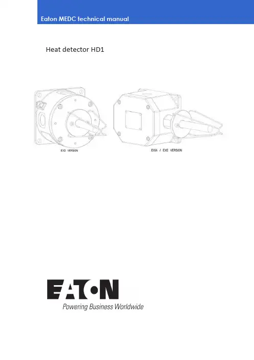
Heat detector HD1Heat detector HD12 HD1 Heat Detector TM159 J October 2024 DISCLAIMER OF WARRANTIES AND LIMITATION OF LIABILITYThe information, recommendations, descriptions and safety notations in this document are based on Eaton Corporation’s (“Eaton”) experience and judgment and may not cover all contingencies. If further information is required, an Eaton sales office should be consulted. Sale of the product shown in this literature is subject to the terms and conditions outlined in appropriate Eaton selling policies or other contractual agreement between Eaton and the purchaser.THERE ARE NO UNDERSTANDINGS, AGREEMENTS, WARRANTIES, EXPRESSED OR IMPLIED, INCLUDING WARRANTIES OF FITNESS FOR A PARTICULAR PURPOSE OR MERCHANTABILITY, OTHER THAN THOSE SPECIFICALLY SET OUT IN ANY EXISTING CONTRACT BETWEEN THE PARTIES. ANY SUCH CONTRACT STATES THE ENTIREOBLIGATION OF EATON. THE CONTENTS OF THIS DOCUMENT SHALL NOT BECOME PART OF OR MODIFY ANY CONTRACT BETWEEN THE PARTIES.In no event will Eaton be responsible to the purchaser or user in contract, in tort (includingnegligence), strict liability or other-wise for any special, indirect, incidental or consequential damage or loss whatsoever, including but not limited to damage or loss of use of equipment, plant or power system, cost of capital, loss of power, additional expenses in the use of existing power facilities, or claims against the purchaser or user by its customers resulting from the use of the information, recommendations and descriptions contained herein. The information contained in this manual is subject to change without notice.Heat detector HD13 HD1 Heat Detector TM159 J October 2024 ContentsIntroduction............................................. 4 General safety messages and warnings........ 4 Installation.............................................. 4 General.................................................... 4 Removing/Replacing the cover............... 4 Operation......................................................... 5 Maintenance.................................................... 5 Certification / approvals................................... 6 Exd IIB Version.......................................... 6 Exd IIC Version.. (6)Ex em Version (6)Ex ia Version............................................. Special conditions of use………………………6 7Heat detector HD14 HD1 Heat Detector TM159 J October 2024 1.0 INTRODUCTIONThe HD1 heat detector has been designed for use in flammable atmospheres and harsh environmental conditions. The marine grade alloy (Exd) or Glass Reinforced Polyester (Exem and Exia versions) cover and enclosure are suitable for use offshore or onshore, where light weight combined with corrosion resistance and strength is required.2.0 GENERAL SAFETY MESSAGES AND WARNINGSAll instructions and safety messages in this manual must be followed to allow safe installation of the device. The device must only be installed and maintained by correctly trained site personnel/installers.i. To reduce the risk of ignition of hazardousatmospheres and shock, do not apply power to the device until installation has been completed and the device is fully sealed and secured. ii. To reduce the risk of ignition of hazardousatmospheres and shock, keep device tightly closed when the circuit is energised.iii. Before removing the cover for installation ormaintenance, ensure that the power to the device is isolated.iv. Following installation, test the device to ensurecorrect operation.v. Following installation ensure a copy of this manualis made available to all operating personnel. vi. When installing the device, requirements forselection, installation and operation should be referred to e.g. IEE Wiring Regulations and the National Electrical Code’ in North America.Additional national and/or local requirements may also apply.vii. Cable termination should be in accordance withspecification applying to the required application. MEDC recommends that all cables and cores should be correctly identified. Please refer to the wiring diagram in this manual (or separate diagram provided with the unit).viii. Ensure that only the correct listed or certified cableglands are used and that the assembly is shrouded and correctly earthed.ix. Ensure that only the correct listed or certifiedstopping plugs are used to blank off unused gland entry points and that the NEMA/IP rating of the unit is maintained.x. MEDC recommend the use of a sealing compoundsuch as HYLOMAR PL32 on the threads of all glands and stopping plugs in order to maintain the IP rating of the unit.xi. For the Exem and Exia versions, a suitable sealingwasher must be fitted to all glands and stopping plugs fitted into the enclosure.xii. The internal earth terminal, where fitted,must be used for the equipmentgrounding and the external terminal, if available, is for a supplementary bonding connection where local codes or authorities permit or require such a connection.xiii. When installing the device, MEDCrecommends the use of stainless steel fasteners. Ensure that all nuts, bolts and fixings are secure.xiv. Note: The purchaser should make themanufacturer aware of any externaleffects or aggressive substances that the equipment may be exposed to.xv. Potential electrostatic charging hazard,protect from direct airflow from exhaust ducts and the like which may cause charge transfer. If the unit requires cleaning, only clean the exterior with a damp cloth to avoid electrostatic charge build up. Ensure the equipment is correctly earthed.xvi. Installation shall be in accordance withIEC60079-14.3.0 INSTALLATIONGeneralThe heat detector is mounted via 4 off Ø9mm (Exd version) or 4 off Ø7mm (Exem and Exia versions) fixing holes in feet on the base of the unit.The fixing holes have been designed to accept M8(Exd version) or M6 (Exe/Exi versions) screws or bolts.The heat detector has been designed to operate in any attitude.Removing/replacing the Cove rExd version: Unscrew and remove the 4 off M6 screws (5mm A/F hexagon key required) and lift the cover clear of the base. The screws are not captive and should be kept in a safe place during cable termination.Exem/Exi versions: Unscrew the 4 off M5 screws (4mm A/F hexagon key required) and lift the cover clear of the base. The cover screws are captive and will be retained in the cover.Once cable termination has been completed, the cover can be replaced and secured to the enclosure. Ensure that any cover seal is correctly seated.On Exd versions ensure that the gap between the cover and enclosure is 0.15mm max. .Heat detector HD15 HD1 Heat Detector TM159 J October 2024 4.0 OPERATIONThe heat detector consists of a sealed element containing a single normally open (N.O.) thermal switch which operates at a fixed temperature. The operatingtemperature is stated on the identification label on the outside of the unit.The sensor element is fully sealed, and no attempt must be made to modify this in any way. Adjustment of the temperature setting is not possible.General arrangement (exd version)General arrangement (exe/exi versions)5.0 MAINTENANCEDuring the working life of the heat detector it should require little or no maintenance. However, if abnormal or unusual environmental conditions occur due toplant damage or accident etc., then visual inspection is recommended.If a fault should occur, then the unit can be repaired by MEDC.Under no circumstances should any attempt be made to either unscrew the heat detector element from the enclosure or gain access to the inside of the heat detector element.Either of these actions will result in the assembly becoming unsafe for use in potentially explosive atmospheres.If you have acquired a significant quantity of heat detectors, then it is recommended that spares are also made available. Please discuss your requirements with MEDC’s technical sales engineers.If the unit requires cleaning, only clean exterior with a damp cloth to avoid electro-static charge build up.Heat detector HD16 HD1 Heat Detector TM159 J October 2024 6.0 CERTIFICATION / APPROVALSExd IIB version: Certified toATEX: EN60079-0 , EN60079-1 , EN60079-31, IEC60079-33IECEx: IEC60079-0 , IEC60079-1 , IEC60079-31, IEC60079-33Ex d unit(ATEX certification No. Baseefa 03ATEX0447) (IEC certification No. IECEx SGS 24.0013X.)Ex db sb IIB+H2 T6 (Tamb -20°C to +55°C) Ex tb IIIC T85°C Db IP6x OrEx db sb IIB+H2 T3 (Tamb -20°C to +125°C)* Ex tb IIIC T200°C Db IP6x*Please refer to certification label for temperature ratingExd IIC version: Certified toATEX: EN 60079-0, EN 60079-1, EN60079-31, IEC60079-33IECEx: IEC60079-0 , IEC60079-1 , IEC60079-31, IEC60079-33Ex d unit(ATEX certification No.Baseefa08ATEX0320) (IEC certification No. IECEx SGS 24.0012X.)Ex db sb IIC T6 Gb (Tamb -20°C to +55°C) Ex tb IIIC T85°C Db IP6X OrEx db sb IIC T4 Gb (Tamb -20°C to +90°C) Ex tb IIIC T135°C Db IP6XFor Type HD1 Addressable Heat Detector Units which do contain an addressable module the marking remains as:Ex db sb IIC T6 Gb (Tamb -20°C to +55°C) Ex tb IIIC T85°C Db IP6XThe Exd ATEX certificate and product label carry the ATEX group and category marking:II 2 GD Where:Signifies compliance with ATEXII Signifies suitability for use in surface industries 2 Signifies suitability for use in a zone 1 areaG Signifies suitability for use in the presence of gases D Signifies suitability for use in the presence of dustThe IECEx certificate and product label carry the IECEx equipment protection level markingGb and Db where Gb signifies suitability for use in a Zone 1 surface industries area in the presence of gas.Db suitability for use in a Zone 21 surface industries area in the presence of dust.Exe version: Certified toATEX: EN60079-0 , EN60079-7, IEC60079-33 IECEx: IEC60079-0, IEC60079-7, IEC60079-33(ATEX certification No. Baseefa03ATEX0428) (IEC certification No. IECEx SGS 24.0035X) Ex eb sb IIC T6 Gb (-20°C to +55°C) (With resistors fitted)Ex eb mb sb IIC T4 Gb (-20°C to +55°C)The ATEX certificate and product label carry the ATEX group and category marking:II 2 G Where:Signifies compliance with ATEXII Signifies suitability for use in surface industries 2 Signifies suitability for use in a zone 1 areaG Signifies suitability for use in the presence of gasesThe IECEx certificate and product label carry the IECEx equipment protection level marking GbWhere Gb signifies suitability for use in a Zone 1 surface industries area in the presence of gas.Ex ia version:ATEX: Certified to EN60079-0 & EN60079-11 IECEx: Certified to IEC60079-0 & IEC60079-11(ATEX certification No. Baseefa03ATEX0427) (IEC certification No. IECEx BAS 13.0010)Ex ia IIC T6 Ga (-55°C to +55°C) - HD1I version Ex ia IIC T4 Ga (-55°C to +55°C) - HD1IR versionThe Ex ia ATEX certificate and product label carry the ATEX group and category marking:II 1 G Where:Signifies compliance with ATEXII Signifies suitability for use in surface industries 1 Signifies suitability for use in a zone 0 areaG Signifies suitability for use in the presence of gasesThe IECEx certificate and product label carry the IECEx equipment protection level marking Ga.Where Ga signifies suitability for use in a Zone 0 surface industries area in the presence of gas.Heat detector HD17 HD1 Heat Detector TM159 J October 2024 7.0 SPECIAL CONDITIONS OF USEExd IIB/IIC version:1. Cover screws of minimum grade A4-80stainless steel shall be used. 2. Warning – Potential electrostaticcharging hazard – See instructions.Exe version:For HD1R units only:1. The electrical supply to the encapsulatedResistor is limited to a maximum of 1.2W 2. Units fitted with the encapsulated resistorshall be protected by a fuse rated for a prospective short circuit current of at least 1500A .Heat detector HD18HD1 Heat Detector TM159 J October 2024 EatonEMEA Headquarters Route de la Longeraie 7 1110 Morges, Switzerland Eaton.euEatonUnit B, Sutton Parkway Oddicroft Lane Sutton in Ashfield United Kingdom NG17 5FBT: +44 (0) 1623 444 400 /hac*******************© 2024 EatonAll Rights Reserved Printed in September Publication No. TM159/J Changes to the products, to the information contained in this document, and to prices are reserved; so are errors and omissions. Only order confirmations and technical documentation by Eaton is binding. Photos and pictures also do not warrant a specific layout or functionality. Their use in whatever form is subject to prior approval by Eaton. The same applies to Trademarks (especially Eaton, Moeller, and Cutler-Hammer). The Terms and Conditions of Eaton apply, as referenced on Eaton Internet pages and Eaton order confirmations.Eaton is a registered trademark.All trademarks are property of their respective owners.。
伊顿并联混合动力系统参数设置摘要:1.医联体医师诊疗奖惩制度的背景和意义2.医联体医师诊疗奖惩的具体措施3.医联体医师诊疗奖惩制度的实施效果4.医联体医师诊疗奖惩制度的存在问题和改进方向正文:一、医联体医师诊疗奖惩制度的背景和意义随着我国医疗体制改革的深入推进,医联体作为新型医疗服务体系的重要组成部分,逐渐成为实现分级诊疗、双向转诊、上下联动、急慢分治的重要途径。
在这个过程中,建立健全医联体医师诊疗奖惩制度,对于提高医疗服务质量、激励医师积极性和创造力具有重要意义。
二、医联体医师诊疗奖惩的具体措施1.建立绩效考核制度:通过制定科学合理的绩效考核指标,对医师的诊疗质量、服务效率、费用控制等方面进行量化评估,实现奖优罚劣。
2.设立奖励与惩罚措施:对于表现优异的医师,给予一定的物质和精神奖励,如奖金、晋升机会等;对于诊疗质量不高、服务态度恶劣的医师,给予相应的处罚,如扣发奖金、降低职称等。
3.完善培训与教育机制:加强对医师的业务培训和职业道德教育,提高其诊疗水平和服务素质,使其更好地适应医联体发展的需要。
三、医联体医师诊疗奖惩制度的实施效果医联体医师诊疗奖惩制度的实施,有助于提高医师的诊疗水平和服务质量,提升患者满意度,促进医联体良性发展。
同时,通过奖惩制度的激励和约束作用,引导医师合理使用医疗资源,降低医疗费用,提高医疗服务效率。
四、医联体医师诊疗奖惩制度的存在问题和改进方向1.考核指标不够科学合理,需要进一步完善,使之更加符合医疗实际和患者需求。
2.奖惩措施力度不够,对于部分医师来说,奖惩效果不明显。
需要加大对优秀医师的奖励力度,同时对不合格医师加大处罚力度。
3.培训教育机制不够完善,需要加强对医师的业务培训和职业道德教育,提高其综合素质。
总之,医联体医师诊疗奖惩制度在推动医联体发展、提高医疗服务质量等方面发挥了积极作用,但仍存在一些问题和不足。
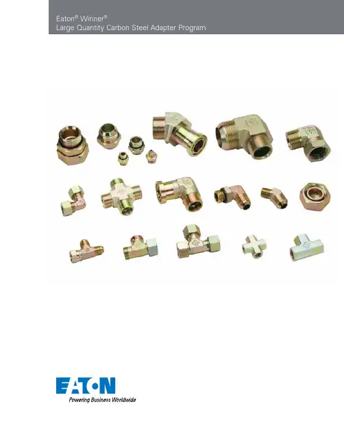
Eaton® Winner®Large Quantity Carbon Steel Adapter ProgramABCDEF2EATON Winner Carbon Steel Adapters E-MEAD-MC002-E April 2011Eaton® Winner®Carbon Steel Adapter Program Table of ContentsSection AJIC 74° (37°) Cone Flared Carbon Steel Adapters and SAE ORB Plugs 1J A-2 1J9 A-3 1JH A-3 1JN A-4 1JN4 A-5 1JN9 A-6 1JN9- A-7 1JN9- A-7 1JO A-8 1JO4-OG A-9 1JO9-OG A-10 1JO9-OG/ A-11 1JO- A-11 2J A-12 2J4 A-12 2J9 A-13 2NJ A-13 2OJ A-14 4ON A-14 4J A-15 4O A-15 5J A-16 5JN A-16 5JN9 A-17 5O A-17 6J-N A-18 6J4 A-18 6J9-N A-19 6NJ-N A-19 AJ A-20 AJ6JJ-N A-20 AJJ6J-N A-21 AJJN A-21 AJNJ A-22 AJJO-OG A-22 AJOJ-OG A-23 BJ A-23 CJ A-24 NB200 A-24 NB300 A-25 NB500 A-25Section BORFS Adapters1FN B-2 1FN9-16 B-2 1FO B-3 1FO4-OG B-3 1FO9-OG B-4 2F9 B-4 4F B-5 6F-L N B-56F9 B-69F B-6AFFO-OG B-7CF B-7Section CNPT Adapters1N C-21N9 C-24N C-34NN C-35N C-45N4 C-55N9 C-55ON C-65ON9-OG C-67N C-77N9-PK C-77NJ-S C-8GN-PK C-8HN C-9JN C-9ZN C-10Section DNPSM Adapters2NU D-22NU4 D-22NU9 D-32OU9-OG D-37NU-S D-4Section EFlange Adapters1JFL E-21JFL9 E-21JFS E-3Section FTechnical InformationWorking Pressure F-2Port Type and Dimensions F-4Recommended Thread Torque F-12Seal Specifications F-133EATON Winner Carbon Steel Adapters E-MEAD-MC002-E April 2011A B C D E FABCDEF4EATON Winner Carbon Steel Adapters E-MEAD-MC002-E April 2011JIC 74° (37°) Cone Flared Carbon Steel Adapters and SAE ORB PlugsPart No. IndexA-1EATON Winner Carbon Steel Adapters E-MEAD-MC002-E April 2011AEaton ®Winner ®JIC 74° (37°) Cone Flared Carbon Steel AdaptersThread Dimensions Part NumberEFAB L S11J-04Z 7/16"X207/16"X2014.014.03512Note: Nut and sleeve should be ordered separately. The nut NB200 and sleeve NB500 is suitable for metric tube, the nut NB200 and sleeve NB300 is suitable for inch tube.JIC Male 74° (37°) Cone1JA-2EATON Winner Carbon Steel Adapters E-MEAD-MC002-E April 2011AThread Dimensions Part NumberEFABS11J9-04Z 7/16"X20 7/16"X20 24.5 24.5 11Note: Nut and sleeve should be ordered separately. The nut NB200 and sleeve NB500 is suitable for metric tube, the nut NB200 and sleeve NB300 is suitable for inch tube.90° Elbow JIC Male 74° (37°) Cone1J91JHThread O-ring Dimensions Part Number EFF A BL S11JH-04-10Z 7/16”X20 M10X1O08.1X1.6 14 8.5 30 14Note: 1. Nut and sleeve should be ordered separately. The nut NB200 and sleeve NB500 is suitable for metric tube, the nut NB200 and sleeve NB300 is suitable for inch tube.2. F end is fit for ISO 9974-1 port or ISO 6149-1 port when useless of retaining ring.JIC Male 74° (37°) Cone / Metric Male Adjustable Stud End L-Series ISO 6149-31JHA-3EATON Winner Carbon Steel Adapters E-MEAD-MC002-E April 2011A1JNThread Dimensions Part Number EFAB L S11JN-04-02Z 7/16"X201/8"X27 14.0 10.5 30.5 12Note: Nut and sleeve should be ordered separately. The nut NB200 and sleeve NB500 is suitable for metric tube, the nut NB200 and sleeve NB300 is suitable for inch tube.JIC Male 74° (37°) Cone / NPT Male1JNA-4EATON Winner Carbon Steel Adapters E-MEAD-MC002-E April 2011A45° JIC Male 74° (37°) Cone / NPT Male1JN47Thread Dimensions Part No.EFAB S1A-5EATON Winner Carbon Steel Adapters E-MEAD-MC002-E April 2011A1JN9Thread Dimensions Part Number EFAB S11JN9-04Z 7/16"X201/4"X18 26.6 25.5 141JN9-32Z 2-1/2"X122"X11.5 75.4 67.5 63Nut and sleeve should be ordered separately. The nut NB200 and sleeve NB500 is suitable for metric tube, the nut NB200 and sleeve NB300 is suitable for inch tube.90° Elbow JIC Male 74° (37°) Cone / NPT Male1JN9A-6EATON Winner Carbon Steel Adapters E-MEAD-MC002-E April 2011A1JN9-LThread Dimensions Part Number EFAB S11JN9-04-02LZ 7/16”X20 1/8”X27 24.5 30 11Nut and sleeve should be ordered separately. The nut NB200 and sleeve NB500 is suitable for metric tube, the nut NB200 and sleeve NB300 is suitable for inch tube.90° JIC Male 74° (37°) Cone / Long NPT Male1JN9-L74°1JN9Thread Dimensions Part NumberEF AB S11JN9-04-02LLZ 7/16"X20 1/8"X27 24.5 39.6 11Nut and sleeve should be ordered separately. The nut NB200 and sleeve NB500 is suitable for metric tube, the nut NB200 and sleeve NB300 is suitable for inch tube.90° Elbow JIC Male 74° (37°) Cone / Longer NPT Male1JN9-LLA1JOThread O-Ring Dimensions 1JO-24-20Z 1-7/8”X121-5/8”X12O92027.515.0961.550Note: Nut and sleeve should be ordered separately. The nut NB200 and sleeve NB500 is suitable for metric tube, the nut NB200 and sleeve NB300 is suitable for inch tube.JIC Male 74° (37°) Cone /O-Ring Boss L-Series ISO 11926-31JOA1JO4-OGThread O-Ring Dimensions Part NumberEF FAB S1S21JO4-04OGZ 7/16”X20 7/16”X20O904 21 24.0 11 171JO4-20OGZ 1-5/8”X12 1-5/8”X12O920 42 48.5 41 50Note: 1. Nut and sleeve should be ordered separately. The nut NB200 and sleeve NB500 is suitable for metric tube, the nut NB200 and sleeve NB300 is suitable for inch tube. 2. F end is connected with ISO 11926-1 port.45° Elbow JIC Male 74° (37°) Cone / SAE O-ring Boss L-Series ISO 11926-31JO4-OG74°A1JO9-OGThread O-Ring Dimensions Part NumberEF FAB S1S21JO9-04OGZ 7/16"X20 7/16"X20 O904 24.5 27.2 11 1790° Elbow JIC Male 74° (37°) Cone / SAE O-ring Boss L-Series ISO 11926-31JO9-OGNote: 1 Nut and sleeve should be ordered separately. The nut NB200 and sleeve NB500 is suitable for metric tube, the nut NB200 and sleeve NB300 is suitable for inch tube. 2 F end is connected with ISO 11926-1 port.74ANote: 1. Nut and sleeve should be ordered separately. The nut NB200 and sleeve NB500 is suitable for metric tube, the nut NB200 and sleeve NB300 is suitable for inch tube. 2. F end is connected with ISO 11926-1 port.Thread O-Ring Dimensions Part Number EF FAB S1S21JO9-06OGLZ 9/16"X18 9/16"X18 O906 26.9 52.8 14 1990°JIC Male 74° (37°) Cone / Long SAE O-ring Boss L-Series ISO 11926-31JO9-OG/LNote: Nut and sleeve should be ordered separately. The nut NB200 and sleeve NB500 is suitable for metric tube, the nut NB200 and sleeve NB300 is suitable for inch tube.1JO-LThread O-Ring Dimensions Part Number EFFAB L S11JO-08LAZ 3/4"X163/4"X16 O908 48 11.1 67.5 22Long JIC Male 74° (37°) Cone / SAE O-ring Boss L-Series ISO 11926-31JO-LANote: Nut and sleeve should be ordered separately. The nut NB200 and sleeve NB500 is suitable for metric tube, the nut NB200 and sleeve NB300 is suitable for inch tube.2JThread Dimensions Part Number EFAB L S1S22J-08-10Z 3/4"X16 7/8"X14 16.7 13 36.5 22 27JIC Male 74° (37°) Cone / JIC Female 74° (37°) Seat2J74°2J4Thread Dimensions Part Number EFAB S1S22J4-04Z 7/16"X20 7/16"X20 21.5 911152J4-20Z 1-5/8"X121-5/8"X12 43.017 41 50Note: Nut and sleeve should be ordered separately. The nut NB200 and sleeve NB500 is suitable for metric tube, the nut NB200 and sleeve NB300 is suitable for inch tube.45° Elbow JIC Male 74° (37°) Cone / JIC Female 74° (37°) Seat2J4A2J9Thread Dimensions Part NumberEF AB S1S22J9-04Z 7/16"X20 7/16"X20 24.5 9111590° Elbow JIC Male 74° (37°) Cone / JIC Female 74° (37°) Seat2J9Note: Nut and sleeve should be ordered separately. The nut NB200 and sleeve NB500 is suitable for metric tube, the nut NB200 and sleeve NB300 is suitable for inch tube.2NJThread Dimensions Part Number EFAB L S1S22NJ-02-04Z 1/8"X27 7/16"X2010.5 9.024.512152NJ-20Z 1-1/4"X11.51-5/8"X12 26.517.0 56.0 46 50NPT Male / JIC Female 74° (37°) Seat2NJASAE O-ring Boss / JIC Female 74° (37°) Seat2OJ2OJ Thread O-Ring Dimensions Part No.EFE A B LS1S220J-16Z 1-5/16"X121-5/16"X12091615.116.038.538414ONThread O-RIng Dimensions Part Number E E AL S14ON-04Z 7/16"X20 09049.111.5 54ON-08Z 3/4"X16090811.114.3 8SAE O-ring Boss Hollow Hex Plug4ONA4JThread Dimensions Part Number EAL S14J-04Z 7/16"X2014.020124J-32Z 2-1/2"X1233.9 5265Note: Nut and sleeve should be ordered separately. The nut NB200 and sleeve NB500 is suitable for metric tube, the nut NB200 and sleeve NB300 is suitable for inch tube.4J4OThread O-Ring Dimensions Part Number E E AL S14O-04Z 7/16"X20 0904 9.1517.014SAE O-ring Boss Plug4OAThread Dimensions Part NumberEFAL S1B5J-04-06SZ 7/16"X20 9/16"X1814.024.619 9.8Note: Nut and sleeve should be ordered separately. The nut NB200 and sleeve NB500 is suitable for metric tube, the nut NB200 and sleeve NB300 is suitable for inch tube.JIC Male 74° (37°) Cone / JIC Female 74° (37°) Seat5J 5JSThread Dimensions Part NumberEFAL S15JN-04Z 7/16"X20 1/4"X1814.035.519Note: Nut and sleeve should be ordered separately. The nut NB200 and sleeve NB500 is suitable for metric tube, the nut NB200 and sleeve NB300 is suitable for inch tube.JIC Male 74° (37°) Cone / NPT Female5JNA5JN9Thread Dimensions Part Number EFAB S15JN9-04Z 7/16"X20 1/4"X1830.922.4 19Note: Nut and sleeve should be ordered separately. The nut NB200 and sleeve NB500 is suitable for metric tube, the nut NB200 and sleeve NB300 is suitable for inch tube.90° Elbow JIC Male 74° (37°) Cone / NPT Female5JN95OThread O-Ring Dimensions Part NumberEFE AB S15O-12-06Z 1-1/16"X129/16"X18O91215.0926.0325O-20-16Z 1-5/8"X121-5/16"X12 O92015.1 42.0 50SAE O-ring Boss L-SeriesISO 11926-3 / SAE Female ISO 11926-15OANote: “LN” in part number designates the adapter with lock nut. Nut and sleeve should be ordered separately. The nut NB200 and sleeve NB500 is suitable for metric tube, the nut NB200 and sleeve NB300 is suitable for inch tube.6J-LNThread Dimensions Part Number EFAB L S1S26J-04LNZ 7/16"X20 7/16"X2014.032.552.51717JIC Male 74° (37°) Cone Bulkhead6J-LN6J4Thread Dimensions Part Number EFAB S1S26J4-06LNZ 9/16”X189/16”X1823.042.414226J4-16LNZ 1-5/16”X121-5/16”X1237.865.0334145° JIC Male 74° (37°) Cone6J4ANote: “LN” in part number designates the adapter with lock nut. Nut and sleeve should be ordered separately. Nut and sleeve should be ordered separately. The nut NB200 and sleeve NB500 is suitable for metric tube, the nut NB200 and sleeve NB300 is suitable for inch tube.6J9Thread Dimensions Part NumberEF AB S1S26J9-04LNZ 7/16"X20 7/16"X20 24.5 40.4 11 176J9-16LNZ 1-5/16"X12 1-5/16"X1250.071.0 33 4190° JIC Male 74° (37°) Cone Bulkhead6J9-LN6NJThread Dimensions Part Number EFAB L S1S26NJ-04-06LNZ 1/4"X18 9/16"X18 15.0 32.5 55.5 22 226NJ-16LNZ 1"X11.5 1-5/16"X12 25.5 44.5 83.0 41 41Note: “LN” in part number designates the adapter with lock nut. Nut and sleeve should be ordered separately. Nut and sleeve should be ordered separately. The nut NB200 and sleeve NB500 is suitable for metric tube, the nut NB200 and sleeve NB300 is suitable for inch tube.NPT Male / JIC Male 74° (37°) Cone Bulkhead6NJ-LNANut and sleeve should be ordered separately. The nut NB200 and sleeve NB500 is suitable for metric tube, the nut NB200 and sleeve NB300 is suitable for inch tube.AJThread Dimensions Part Number EF GA BC S1AJ-04Z7/16"X20 7/16"X20 7/16"X20 24.5 24.5 24.511AJ-16Z 1-5/16"X121-5/16"X121-5/16"X12 49.0 49.0 49.0 33JIC Male 74° (37°) ConeAJNote: “LN” in part number designates the adapter with lock nut. Nut and sleeve should be ordered separately. The nut NB200 and sleeve NB500 is suitable for metric tube, the nut NB200 and sleeve NB300 is suitable for inch tube.AJ6JJThread Dimensions Part Number EF GA BC S1S2AJ6JJ-06LNZ9/16"X18 9/16"X18 9/16"X18 26.9 46.0 26.9 14 22JIC Male 74° (37°) ConeAJ6JJ-LNAThread Dimensions Part NumberEF GA BC S1S2Note: “LN” in part number designates the adapter with lock nut. Nut and sleeve should be ordered separately. The nut NB200 and sleeve NB500 is suitable for metric tube,the nut NB200 and sleeve NB300 is suitable for inch tube.JIC Male 74° (37°) ConeAJJ6J-LN74AJJNThread Dimensions Part Number EF GAB C S1AJJN-04Z 7/16"X20 7/16"X20 1/4"X18 26.6 26.6 25.514AJJN-16Z 1-5/16"X121-5/16"X12 1"X11.549.049.0 50.0 33Nut and sleeve should be ordered separately. The nut NB200 and sleeve NB500 is suitable for metric tube, the nut NB200 and sleeve NB300 is suitable for inch tube.JIC Male / JIC Male / NPT MaleAJJNAAJJO-OG Thread O-Ring Dimensions Part NumberEFG GA BC S1S2AJJO-04OGZ7/16"X20 7/16"X20 7/16"X20 O90424.5 24.5 27.21117Note: Nut and sleeve should be ordered separately. The nut NB200 and sleeve NB500 is suitable for metric tube, the nut NB200 and sleeve NB300 is suitable for inch tube.JIC Male / JICMale / SAE O-ring BossAJJO-OGJIC Male / NPT Male / JIC MaleAJNJ74°AJNJ Thread Dimensions Part No.EFGABCS1the nut NB200 and sleeve NB300 is suitable for inch tube.AAJOJ-OG Thread O-Ring Dimensions Part Number EF GF A BC S1S2AJOJ-06OGZ9/16"X18 9/16"X18 9/16"X18 O906 26.9 31.8 26.9 14 19Note: Nut and sleeve should be ordered separately. The nut NB200 and sleeve NB500 is suitable for metric tube, the nut NB200 and sleeve NB300 is suitable for inch tube.JIC Male / SAE O-ring Boss / JIC MaleAJOJ-OG74°BJThread Dimensions Part Number EF GA BC S1S2BJ-04Z7/16"X20 77/16"X20 7/16"X2024.5 924.51115BJ-20Z 1-5/8"X12 1-5/8"X12 1-5/8"X12 56.0 17 56.041 50Note: Nut and sleeve should be ordered separately. The nut NB200 and sleeve NB500 is suitable for metric tube, the nut NB200 and sleeve NB300 is suitable for inch tube.JIC Male / JIC Female / JIC MaleBJA74°CJCJ Thread DimensionsPart Number E F G A B C S1S2 CJ-04Z 7/16"X20 7/16"X20 7/16"X2024.524.5 9.01115CJ-20Z1-5/8"X121-5/8"X121-5/8"X12 55.5 55.51741 50 Note: Nut and sleeve should be ordered separately. The nut NB200 and sleeve NB500 is suitable for metric tube, the nut NB200 and sleeve NB300 is suitable for inch tube.JIC Male / JIC Male / JIC FemaleCJThread Tube O.D. & Sleeve Dimensions Part Number E in.Inch Sleeve mm Metric Sleeve L S2NB200-04Z 7/16"X20 1/4"NB300-046NB500-0615.814JIC Triple Lock NutNB200ANB300Tube Dimensions Part NumberThreadO.D.DLNB300-04Z 7/16"X201/4" 9.7310.4NB300-32Z 2-1/2"X122"61.1930.2JIC Inch SleeveNB300NB305TubeDimensions Part NumberThreadO.D. mm DLNB500-06Z 7/16”X2069.710.4NB500-32Z 1-5/8”X123238.923.1JIC Metric SleeveNB500APart No. Index Page intentionally left blank AORFS AdaptersPart No. Index1FNB-21FOB-31FO9-OGB-42F9B-44FB-56F-LNB-59FB-6AFFO-OGB-7CFB-71FN9-16B-21FO4-OGB-36F9B-6B Eaton® Winner®ORFS AdaptersORFS Male O-ring / NPT Male1FNThread O-Ring Dimensions Part Number EF EA BL S11FN-12Z 1-3/16"X12 3/4"X14 O018 17 19.5 49 32Thread O-Ring Dimensions Part NumberEFEA BS11FN9-16Z 1-7/16"X121"X11.5O02144.551.636Note: E end is connected with ISO 11926-1 port. ORFS fittings utilize a machined half dovetailed groove for seal retention.1FN9-1690° Elbow ORFS MaleO-ring / NPT MaleNote: ORFS fittings utilize a machined half dovetailed groove for seal retention.B1FO4-OGThread O-Ring Dimensions Part NumberEFEFA BL S11FO-04-06Z9/16"X18 9/16"X18 O011 O906 9.812.029.5 171FOORFS Male O-ring /SAE O-ring Boss S-Series ISO 11926-245° Elbow ORFS Male O-ring / SAE O-ring Boss S-Series ISO 11926-2Note: F end is connected with ISO 11926-1 port.ORFS fittings utilize a machined half dovetailed groove for seal retention.ThreadO-Ring Dimensions Part No.EFEFABS1S21FO4-04OGZ 9/16" X187/16" X20O011O90418.326.01417B1FO9-OG1FO9-OGThread O-Ring Dimensions Part NumberEFEF A BS1S21FO9-04OGZ9/16"X18 7/16"X20 O011 O904 23.030.3 14 171FO9-20OGZ 1-11/16”X121-5/8”X12O025O92047.560.54150Note: F end is connected with ISO 11926-1 port. ORFS fittings utilize a machined half dovetailed groove for seal retention.90° Elbow ORFS Male O-ring / SAE O-ring Boss S-Series ISO 11926-22F9Thread O-Ring Dimensions Part NumberEFE A BS1S22F9-06Z11/16"X16 11/16"X16 O012 27.5 10 19 222F9-16Z 1-7/16"X12 1-7/16"X12 O021 44.5 15 36 4190° Elbow ORFS Male O-ring / ORFS FemaleNote: ORFS fittings utilize a machined half dovetailed groove for seal retention.BORFS Male O-ring Plug4FThread O-Ring Dimensions Part NumberE E AL S14F-04Z 9/16"X18 O011 9.8 16.8 174F-20Z 1-11/16"X12 O025 17.5 27.9 466F-LNThread O-Ring Dimensions Part NumberEFEFA BL S1S26F-10LNZ1"X141"X14O016 O016 15.5 40.6 66.6 36 366F-20LNZ 1-11/16"X12 1-11/16"X12 O025 O025 17.5 42.2 70.2 50 50ORFS Male O-ring BulkheadLock NutNote: ORFS fittings utilize a machined half dovetailed groove for seal retention.Note: “LN” in part number designates the adapter with lock nut. ORFS fittings utilize a machined half dovetailed groove for seal retention.B。

伊顿液压接头样本伊顿液压接头是一种高质量的接头产品,其品质和可靠性备受认可。
伊顿公司在液压系统领域拥有多年的经验,产品质量一直处于业界领先水平,大部分液压系统用户对其产品的表现都非常满意。
伊顿液压接头是由优质材料及精密制造工艺制成的,具有高强度、耐磨损、耐高温、抗韧性强等特点。
其设计紧凑,安装简便,使用寿命长,广泛应用于工程机械、风力发电、冶金、采矿、船舶、造纸、农业等领域,深受广大用户的好评。
伊顿液压接头有多种型号和规格可供选择,其尺寸和参数可根据用户的要求进行定制。
此外,伊顿还提供一系列优质的附件,使其产品的功能更为完善。
这些附件包括密封件、接头夹具、螺旋管等,其使用可以进一步提高伊顿液压接头的可靠性和稳定性。
伊顿液压接头的样本可以免费向用户提供,以方便用户在购买产品前进行实际测试和评估。
其样本包括螺纹式、卡箍式、冷压式等多种型号,同时还提供各种不同的材质选择,以满足各类液压系统用户的需求。
用户可以根据自己的实际需求和应用环境,选择最适合自己的伊顿液压接头产品。
伊顿液压接头的使用和维护非常简单,用户只需按照相应的操作步骤和注意事项进行操作和维护即可。
在使用时,用户需要注意液压系统的压力和温度范围,以免影响液压接头的使用寿命。
在维护时,用户需要定期检查液压接头的连接部位和密封件的状况,如发现问题需及时更换。
总之,伊顿液压接头是一种高质量、可靠性强、安装简便的接头产品。
其样本免费提供,用户可以在购买前进行实际测试和评估。
用户在使用伊顿液压接头时,需要注意压力和温度范围,定期维护以确保其长期稳定运行。
伊顿液压接头是液压系统领域中的优秀产品,值得用户的信赖和选择。

Handbuch zum Laden von ElektrofahrzeugenWarum sich für ein Elektroauto entscheiden? Elektrofahrzeuge: Die VorteileWelches sind die verschiedenen Arten vonE-Fahrzeugen und was ist deren Funktionsweise? Der Unterschied zwischen kWh und kWPHEV vs BEVElektrofahrzeug-Ladeinfrastruktur (EVCI) Stecker und Steckdosen für Elektrofahrzeuge Wie man ein Elektrofahrzeug auflädt FahrzeugkompatibilitätWo und wann man ein E-Fahrzeug auflädt Elektrofahrzeuge in der Energiewende Verzeichnis4 68 10 12 14 16 18 22 25 27 29Inhalt20152015100100%8080%6060%4040%2020%00Quelle: BloombergNEFQuelle: BloombergNEF Langfristiger weltweiter Pkw-Absatz nach AntriebsartAnteil am Jahresumsatz2020202020252025203020302035203520402040werden könnten.Verbrenner-Fahrzeuge Brennst-offzelle PHEV Ver-brenner-Fahrzeuge E-Fah-rzeugeE-FahrzeugeWelches sind die verschiedenen ArtenElektrofahrzeug (BEV)Es ist wichtig, zwischen den beiden gebräuchlichsten Abkürzungenim Zusammenhang mit dem Laden von Elektrofahrzeugen zuunterscheiden: Kilowattstunden (kWh) und Kilowatt (kW).Um zu berechnen, wie lange es dauert, ein Elektrofahrzeug vollaufzuladen, muss man sowohl die Kapazität (in kWh) der Batterie desFahrzeugs als auch die von der Ladestation angebotene Leistung(in kW) kennen.kWh und kWVerbrennungsmotor umschalten.6050403020100d u r c h s c h n i t t l i c he B a t t e r i e k a p a z i t ät (k W h )201420152016201720182019Quelle: Green MotionAutofahrer müssen ihre E-Fahrzeuge zu Hause und unterwegsaufladen können, was bedeutet, dass sie Zugang zu Ladepunktenin Wohngebieten und öffentlichen Einrichtungen wie Tankstellenund Arbeitsplätzen benötigen. Die Aufladung kann entweder mit AC(Wechselstrom) oder DC (Gleichstrom) erfolgen.AC LadetechnikDiese Art der Ladeinfrastruktur ist am günstigsten zu installieren, dader Wechselstrom direkt aus dem Netz kommt. Er kann einphasig (übereinen einzelnen Umrichter) oder dreiphasig (über drei Umrichter für einegrößere Leistungsübertragung) geführt werden. Im gewerblichen undindustriellen Bereich wird fast immer das dreiphasige System verwendet,da es eine effizientere Möglichkeit ist, höhere Ladeleistungen zu erzielen.Die Batterie in einem E-Fahrzeug arbeitet ebenso wie die Batterie ineinem Laptop oder Mobiltelefon mit Gleichstrom. Das bedeutet, dassder Strom von einem AC-Ladegerät von AC in DC umgewandelt werdenmuss, bevor er für die Stromversorgung der Fahrzeugbatterie verwendetwerden kann. Um dies zu ermöglichen, wird der Strom durch dasOnboard-Ladegerät (OBC) des E-Fahrzeugs geleitet, das die Spannungund den Strom reguliert. Die Ladegeschwindigkeit ist abhängig vonder Leistungsabgabe des OBCs. Das bedeutet, dass selbst wenn einElektrofahrzeug mit einem relativ leistungsstarken 22-kW-AC-Ladegerätgeladen wird, die Leistung, die die Batterie erhält - und damit auch,wie schnell sie ihre Kapazität erreicht - von den Kennwerten desOBC abhängt.DC LadetechnikGleichstrom-Ladung erfolgt in der Regel an speziellen Gleichstrom-Ladestationen außerhalb des Hauses, die eine höhere Leistung undschnellere Ladegeschwindigkeiten bieten. Bei der Gleichstromladungwird der Strom innerhalb der Ladestation umgewandelt und direkt zurBatterie geleitet, wobei der potenziell begrenzende OBC umgangenwird. Erste DC-Ladegeräte begannen bei etwa 50 kW, aber derLeistungsbereich der meisten ist jetzt von 20 kW auf mehr als 150 kWgestiegen, im Einklang mit der breiteren Verfügbarkeit von größerenBatteriekapazitäten für Elektrofahrzeuge. Die Verfügbarkeit von Gerätenmit 20 kW bedeutet, dass sich DC-Ladegeräte im Wohnbereichwahrscheinlich zunehmend durchsetzen werden. Außerdem bieten siedem Eigentümer die Möglichkeit, seine Einnahmen zu erhöhen, da dieKapazität der DC-Ladegeräte an Bord höher ist als die der AC-Ladegeräte. Elektrofahrzeug-Ladeinfrastruktur (EVCI)Wie man ein Elektrofahrzeug auflädtEs gibt verschiedene Arten von Ladesteckern für E-Fahrzeuge, jenachdem, ob sie an einen AC- oder DC-Ladepunkt angeschlossenwerden. Der Eingangsanschluss des Fahrzeugs und der Typ desLadegeräts bestimmen, welche Steckdose verwendet werden kann.Mode 1Haushaltssteckdose und Verlängerungskabel (AC)Dabei wird das Elektrofahrzeug über eine normale Haushaltssteckdoseund ein Kabel ohne Schutzeinrichtung an das Netz angeschlossen.Aufgrund des hohen Stromverbrauchs des Ladegeräts über mehrereStunden besteht eine erhöhte Wahrscheinlichkeit von Bränden oderelektrischen Verletzungen, daher wird Mode 1 nicht empfohlen.Mode 2Haushaltssteckdose mit kabelintegriertem FI-Schutzschalter (AC)Das Elektrofahrzeug wird über eine Haushaltssteckdose an dasStromnetz angeschlossen. Das Aufladen erfolgt jedoch über ein Kabelmit eingebautem Schutz (Fehlerstromschutzschalter oder RCD) zumSchutz vor elektrischen Schlägen und Bränden. (Es wird empfohlendie Steckdose bzw. den Anlagenteil der regelmäßig zum Laden vonElektrofahrzeugen verwendet wird, von einer Elektrofachkraft überprüfenzu lassen.)Mode 3Dediziertes EV-Ladesystem (AC)Ein E-Fahrzeug wird über eine spezielle Steckdose, einen Stecker undeinen eigenen Stromkreis an das Netz angeschlossen. Mode 3 kann imprivaten, gewerblichen und öffentlichen Bereich eingesetzt und je nachAnwendung mit unterschiedlichen Leistungen betrieben werden.Mode 4Dediziertes EV-Ladesystem (DC)Der einzige Modus für das DC-Laden, das über einen eigenen Stromkreisund einen Stecker und normalerweise nur an öffentlichen Ladestationenerfolgt. Die Umwandlung von Wechselstrom in Gleichstrom erfolgtinnerhalb der Ladestation, was eine Leistung von ca. 50 kW oder mehrermöglicht, wenn die Versorgung des Standorts dies zulässt.Wie man ein Elektrofahrzeug auflädt DaheimMehrfamilienhaus am ZielortArbeitsplatz UnterwegsMode 2Mode 3 Mode 3Mode 3Mode 3Mode 4Mode 4Mode 41–2 Std. (über Nacht)1–2 Std.(über Nacht)~8 Std.Angestellter~2 Std.Besucher1-2 Std.Besucher8 Std.Angestellte15-20 MinAC DCAC DC AC DCACElektrofahrzeug-Ladeinfrastruktur (EVCI)• Für einphasige 230-V-Anschlüsse, Leistung (kW) = Amp (A) x 230 V*0,001• Für 3-Phasen-400-V-Anschlüsse, Leistung (kW) = 1.732*Amp per Phase (A) x 400 V*0,001**je nach LandFahrzeugkompatibilität PHEVs und BEVs verfügen über sehr unterschiedliche Batteriegrößen, so dass ihre Ladeanforderungen und die Lademethoden, mit denen sie am besten kompatibel sind, unterschiedlich sind.Die Batterie von PHEVs ist kleiner, in der Regel zwischen 6-15 kWh, und der OBC ist im Allgemeinen auf 3,4 kW oder 7,4 kW begrenzt. Angesichts der Größe der mitgeführten Batterie ist Mode 2 am besten für das Laden im Haushalt geeignet, obwohl das schnellere Laden, das Mode 3 bietet, für Batterien am oberen Ende der PHEV-Skala,insbesondere für das Laden unterwegs, vorzuziehen sein könnte. BEVs besitzen größere Batterien, in der Regel von 30 kW bis hin zu 95 kWh für Hochleistungsfahrzeuge, wobei die OBCs von 7 kW bis 22 kW reichen. BEVs können Mode 1, 2 und 3 verwenden, wenn sie es wünschen, aber fast alle sind mit den speziellen Systemen und der zusätzlichen Leistung von Mode 4 kompatibel.Ein Tesla Model 3-Besitzer, der sein Fahrzeug an einer 22-kW-AC-Ladestation auflädt, erhält nur 11 kW, begrenzt durch das Onboard-Ladegerät des Fahrzeugs. Das Aufladen der Batterie dauert 5-7 Stunden. Bei Verwendung einer 50-kW-DC-Ladestation, deren DC-Ladeleistung 145 kW beträgt, gibt es keine Begrenzung und es dauert 40-60 Minuten, um die Batterie zu laden.T op 15 PHEVs und E-Fahrzeuge (bezogen auf den bisherigen Jahresabsatz) im Jahr 2020 in EuropaWo und wann man ein E-Fahrzeug auflädtDas Betanken von ICE-Fahrzeugen basiert auf dem Prinzip, zu tanken, wenn der Tank leer ist. Bei Elektrofahrzeugen sieht das ganz anders aus. Der Fokus muss sich auf das "Gelegenheitsladen" verlagern, bei dem das Laden anderen Aktivitäten, wie dem Einkaufen oder dem Gang zur Arbeit, untergeordnet ist. Das Ergebnis ist ein regelmäßiges Nachladen, um sicherzustellen, dass die Ladung des E-Fahrzeugs nie zu niedrig wird. Um diese Umstellung der Verhaltensmuster zu ermöglichen, wird ein dichtes Netz von Ladestationen stetig ausgebaut. Standorte für das Laden von Elektrofahrzeugen sind:Elektrofahrzeuge in der EnergiewendeElektrofahrzeuge in der EnergiewendeDie wachsende Zahl von E-Fahrzeugen und die entsprechendeInfrastruktur sind nur der Anfang der Mobilitätsrevolution. In derZukunft werden E-Fahrzeuge eine Schlüsselrolle bei der Unterstützungdes Übergangs zu einem Energiesystem spielen, das von variabler erneuerbarer Erzeugung dominiert wird. Bidirektionale Ladestationen fürE-Fahrzeuge ermöglichen es, dass E-Fahrzeugbatterien zur Stabilisierungdes Netzes beitragen, indem sie je nach Energieverfügbarkeit und -bedarf entweder als Stromspeicher oder als Stromquelle fungieren.Indem sie es ermöglichen, dass Energie vom Elektrofahrzeug zumGebäude (und damit zum Netz) fließt und nicht nur vom Gebäude zum Elektrofahrzeug, führen bidirektionale Ladegeräte ein enormes Maß an Flexibilität bei der Nutzung von Elektrofahrzeug-basierten Technologienein, die als V2X (Fahrzeug-zu-Allem), V2G (Fahrzeug-zu-Netz) und V2H (Fahrzeug-zu-Haus) bekannt sind. Dank dieser Technologien kann einE-Fahrzeug für viel mehr als nur für den Transport genutzt werden.Einige Beispiele:• Funktion als Notstromquelle bei Stromausfall• Beitrag zur Stabilisierung des Netzes durch Stromspeicher- und Versorgungsmöglichkeiten• Einnahmen durch den Verkauf von ungenutztem Strom an dasNetz erzielen• Kosteneinsparung durch Speicherung von Energie mit niedrigem Tarifzur Nutzung während der Spitzenlastzeiten• Speicherung von überschüssiger, selbst erzeugter erneuerbarerEnergie, um sie bei Bedarf zu nutzen (was sowohl zur Stabilisierungdes Netzes als auch zu Kosteneinsparungen beiträgt)VerzeichnisAC BEV CCS DCE-Fahr-zeuge EVCI HEVVerbrenner-FahrzeugekWkWhOBCPHEVRCDWechselstromBatteriebetriebenes Elektrofahrzeug (BEV)Kombiniertes LadesystemGleichstromElektrofahrzeugLadeinfrastruktur für ElektrofahrzeugeHybrid-ElektrofahrzeugVerbrenner-FahrzeugKilowattKilowattstundeOn-Board LadegerätPlug-in-HybridfahrzeugFehlerstrom-Schutzschalter(Residual Current Device)tiefreichendem regionalem praktischem Know-how in denBereichen Stromverteilung und Stromkreisschutz, Stromqualität, Notstromversorgung und Stromspeicher, Steuerung undAutomatisierung, Schutzschaltgeräten und Sicherheitsbeleuchtung, strukturelle Lösungen und Lösungen für raue und gefährliche Umgebungen.Durch End-to-End-Services, Vertriebskanäle, eine integrierte digitale Plattform und eine umfassende Kenntnis der Branche treibt Eaton branchenübergreifend und weltweit das voran, worauf es ankommt, und hilft Kunden bei der Lösungihrer kritischsten Herausforderungen im Bereich des elektrischen Energiemanagements.Eaton hat sich das Ziel gesetzt, durch den Einsatz seiner Energiemanagement-Technologien und -Dienstleistungen für mehr Lebensqualität zu sorgen und die Umwelt zu schützen. Die nachhaltigen Lösungen helfen den Kunden, elektrische, hydraulische und mechanische Energie sicherer, effizienter und zuverlässiger zu nutzen. Eaton erzielte im Jahr 2020 einen Umsatz von 17,9 Milliarden Dollar und verkauft Produkte in mehr als 175 Ländern. Weitere Informationen finden Sie unter .Wir behalten uns das Recht auf Änderungen an den Produkten oder den in diesem Dokument enthaltenen Informationen vor. Das gleiche gilt auch für Preise sowie jedwede Fehler und Auslassungen. Verbindlich sind nur die von Eaton erstellten Auftragsbestätigungen und technischen Dokumentationen. Auch Fotos und Abbildungen jeglicher Form sind keine Gewähr für die Gestaltung oderFunktionalität der Produkte. Deren Verwendung in jedweder Weise unterliegt der vorherigen Genehmigung durch Eaton. Dasselbe gilt für Marken (insbesondere Eaton, Moeller und Cutler-Hammer). Es gelten die Allgemeinen Geschäftsbedingungen von Eaton, wie auf denInternetseiten und den Auftragsbestätigungen von Eaton angegeben.Folgen Sie uns in den sozialen Medien und erhalten Sie aktuelle Produkt- und Supportinformationen.Eaton ist ein eingetragenes Markenzeichen.Alle anderen Warenzeichen sind Eigentum ihrer jeweiligen Inhaber.EatonEMEA Hauptverwaltung Route de la Longeraie 71110 Morges, Schweiz © 2021 EatonAlle Rechte vorbehaltenPublikationsnummer: BR191002DE Juni 2021。
提供动力。
探索今天的伊顿。
我们提供:• 方案• • •动及动力总成解决方案马达控制设备命令和控制设备终端保护产品自动化和驱动产品134MOEM 市场综合样本目录2马达和线路控制设备伊顿拥有超过百年的接触器研发和制造经验,为用户提供至3185A 的线路控制解决方案,并提供不同系列的产品以满足用户的的多种要求Xstart 系列接触器:全球化的产品,提供包括UL 在内的主流认证,最高达3185安培(AC-1)的产品:• 独特的CT 型励磁机构,功耗更小;• 115A 以上集成电子线路板,降低功耗同时工作电压幅度更宽;• 580A 以上真空灭弧,应对严苛使用环境,业界最长预期寿命;• 提供本地化的XstartC 系列(认证情况请咨询当地销售办事处)。
D 系列接触器:本地化的产品,提供最高到500A 的高效控制和保护方案,应用于泵、风机、压缩机等场合,提供功能全面的辅助触点和宽幅的控制线圈电压选项。
• 齐全的线圈控制电压,185A 以上更提供交直流通用产品;• 全系列内置辅助触点• 百万次以上电气寿命• 使用温度-20 °C ~ +55 °CE 系列接触器:全球最小的电磁接触器之一,有效地利用空间,可靠性增强,材料使用更高效。
E 系列接触器额定值可至AC-3, 95A@400V ,最高工作电压高达660V ,体积小巧,却提供强大的性能。
• 百万次以上电气寿命• 690V 绝缘额定值• 最多可加装6个辅助触点模块• 常用交流控制电压及直流24VDC 线圈1马达控制设备目录电机控制产品 xStart C 接触器式继电器DILA..C 接触器DILM..C 过载继电器ZB..C电动机保护断路器PKZMC 电机控制产品 D 系列接触器 XTCD 热过载继电器 XTOD 电气行业解决方案 Eline 控制继电器 XTRG 接触器 XTCG热过载继电器 XTOD/XTOG电机控制产品 xStart C电机控制产品 D 系列电气行业解决方案Eline1接触器式继电器DILA..C目录系统概览 . . . . . . . . . . . . . . . . . . . . . . . . . . . . . . . . . . . . . . . . . . . . . . . . . . . . . . . . . . . . . . . . . . . . .本体DILA..C . . . . . . . . . . . . . . . . . . . . . . . . . . . . . . . . . . . . . . . . . . . . . . . . . . . . . . . . . . . . . . . . . .辅助触点模块 . . . . . . . . . . . . . . . . . . . . . . . . . . . . . . . . . . . . . . . . . . . . . . . . . . . . . . . . . . . . . . . .附件 . . . . . . . . . . . . . . . . . . . . . . . . . . . . . . . . . . . . . . . . . . . . . . . . . . . . . . . . . . . . . . . . . . . . . . . . .操作电压 . . . . . . . . . . . . . . . . . . . . . . . . . . . . . . . . . . . . . . . . . . . . . . . . . . . . . . . . . . . . . . . . . . . . .特性曲线,触点行程图 . . . . . . . . . . . . . . . . . . . . . . . . . . . . . . . . . . . . . . . . . . . . . . . . . . . . . . . .技术数据 . . . . . . . . . . . . . . . . . . . . . . . . . . . . . . . . . . . . . . . . . . . . . . . . . . . . . . . . . . . . . . . . . . . . .尺寸 . . . . . . . . . . . . . . . . . . . . . . . . . . . . . . . . . . . . . . . . . . . . . . . . . . . . . . . . . . . . . . . . . . . . . . . . .4极触点多种组合约定发热电流(I th )16A 交流与直流操作的产品尺寸相同直流操作的产品内置浪涌抑制器••••接触器式继电器DILA..C35791112131911接触器式继电器DILA..C说明121接触器式继电器DILA..C系统概览31接触器式继电器DILA..C系统概览4系统概览本体AC 或DC 操作电磁系统AC DC 可以扩展到8对触点反向互锁触点模块化系统螺钉连接和卡装手指接触防护螺钉端子第5页起抑制电路用于直流操作接触器式继电器的保护电路(所有直流型均内置)用于交流操作接触器式继电器的保护电路第32页起辅助触点模块23, 42或4极反向互锁触点第7页起124 – 400V, 50, 60, 50/60 Hz0.8 – 1.1 × U c 24 VA/3.4 VA 24 – 220 V DC0.8 – 1.1 × U c 于24 V :0.7 – 1.3 × U c 无附加辅助触点模块环境温度+40°C 3W/3W1接触器式继电器DILA..C本体5接线方式:螺钉端子触点N/O = 常开N/C = 常闭带反向互锁触点的本体额定工作电流AC – 15220 V230 V240 VI e约定发热电流,敞开,于60°CI th代码序号触点序号380 V400 V415 VI e1本体DILAC-XHI(V)...DILAC-XHI(V)...DILAC-XHI(V)...DILA-40C(220-230V50Hz)114842DILA-31C(220-230V50Hz)114852DILA-22C(220-230V50Hz)114862DILA-40C(24VDC)114847DILA-31C(24VDC)114857DILA-22C(24VDC)1148671件1件1件可以组合辅助触点模块标准包装说明AC 操作型号订货号操作电压220-230V50HzDC 操作型号订货号操作电压24VDC附件1 抑制器2 辅助触点模块操作电压页数32711触点编号,符合EN 50011线圈端子标记,符合EN 50005直流操作的接触器式继电器具有一个内置的保护电路。

伊顿EATON接头eaton简介Eaton在中国授权由------美国伊顿液压旗舰店----田凯文,为客户做技术支持、产品销售、客户服务和产品选型。
parker接头伊顿eaton接头特性伊顿eaton卡套式管接头因其特有的装配方便(仅需两把扳手)而广受欢迎。
经过近80多年的发展,EO工厂始终保持着卡套式管接头技术的领先地位。
今天,伊顿eaton管接头是世界上使用最为广泛的一种管接头。
EO管接头是为公制管子设计的,历史上曾经依照德国标准DIN3861、DIN3859和DIN2353,现在这些标准已被国际标准ISO8434取代。
Parker管接头以体积小,压力等级高而著称。
分为低压、中压和高压三个系列(LL、L、S系列)这样使得各种不同的应用场合可以实现最经济化和空间最小化的方案。
伊顿eaton材质及规格原装进口eaton管接头的材料除了最常见的碳钢镀锌以外,还提供铜和不锈钢两种材料,以适应不同的流体或环境条件。
Parker不锈钢接头的螺母螺纹采用镀银并预先润滑(规格15L-42L,12S-38S),较小规格的螺母螺纹采用蜡封,这样不仅有效的消除了不锈钢螺纹的咬合现象,同时减少40%装配拧紧力矩。
Eaton管接头具有50多种不同的形式,可供各种不同应用场合的灵活选择,加上许多eaton功能管接头,如旋转接头、球阀、单向阀、截止阀、测压接头等与eaton管接头配合使用,可大大方便系统的配套,提高系统密封的可靠性。
伊顿eaton液压软管具有防腐、耐高温、抗拉强度高,柔韧性好等诸多性能,而被广泛采用在各行业的液压工程中,派克软管有一层至多层钢丝编织增强层( 6 层以上),有低、中、高、超高三种压力等级,有轻、重两系列,公称通径在 3 — 32mm 。
有普通型和特殊型两种软管以满足在普通环境及特殊环境下使用,先进的不剥胶软管极大减轻装配劳动强度,广泛应用在各行业液压系统管路中。
美国派克液压旗舰店,将为你提供高压管接头以及软管各种配件,选择了我们,就是选择了终端液压提供商。
伊顿永华接头样本
?
Winner
软管总成 Hose Assembly
软管总成 Hose Assembly
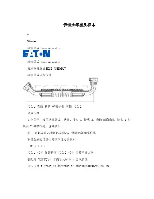
液压软管总成HOSE ASSEMBLY
软管总成订货代号
接头1 套筒软管弹簧护套套筒接头2
总成长度
如上图示,液压软管总成由软管、接头1、接头 2、套筒扣压而成。
接头 1 与接头 2 可以相同,也可以不
同,可以是直芯也可以是弯芯,弹簧护套可以不用。
软管总成的订货代号按下述方法表示:
,RS / X X /
接头1 代号弹簧护套接头2 代号自然弯曲方向
装配角软管代号( 含简号及标号 ) 总成长度
订货示例 1:22641-08-08/22691-12-08X1T08X1000V90/SSX+RS;
当无装配角、自然弯曲方向或弹簧护套时,则代号中这些内容可省去不写。
订货示例 2:当接头 1 与接头 2 相同时,只标一个接头的代号。
22691-08-
08X1T08X1000V90
A-01
液压软管总成HOSE ASSEMBLY
软管总成长度测量
软管总成长度L 以从接头芯端面或弯接头芯中心为基准进行测量。
如下图示。
管芯及管端管端
管端中心及管芯管端及管端中心
管芯中心线管端及管端中心
A-02。
FSM FUNCTIONAL SAFETY MANAGEMENTThese products are able to be used within a Safety System conforming to the requirements ofIEC 61508:2010 or IEC 61511. The products are not Safety Elements but may be used toprotect instrument loops designed to achieve Safety Integrity Level of up to SIL3.Eaton is a certified Functional Safety Management company meeting the requirements of IEC61508 Part1:clause 62SM MTLSurge rev 3This manual supports the application of the products in functional safety related loops. It must beused in conjunction with other supporting documents to achieve correct installation, commissioningand operation. Specifically, the data sheet, instruction manual and applicable certificates for theparticular product should be consulted, all of which are available on the Eaton web site.In the interest of further technical developments, Eaton reserve the right to make design changes.Contents1 Introduction31.1 Applicationandfunction 31.2 Variantdescription 32 System configuration42.1.1 Input/outputcharacteristics 52.1.2 Associated system components 53 Selection of product and implications 64 Assessment for use inFunctional Safety applications 64.1 EMC 84.2 Environmental85 Installation87 M aintenance88 Appendices9 Machine Monitor Interfaces1 Introduction1.1 Application and functionThe products concerned in this manual are ‘Surge Protection’ devices which can be located in safe or hazardousareas of a process plant to guard against the direct and indirect effects of lightning, or other transient overvoltage,on the instrumentation and power signals. They are also designed and tested according to IEC 61643-21 (Lowvoltage surge protective devices) for use in signal and communication loops.The location, or mounting, of the surge protection device is a key parameter when considering the operationof the device and the consequences of breakdown or failure upon the operation of the signal loop to which itis connected.The TP family of products are designed to protect field-mounted equipment, such as process measurement transmitters for level, flow, pressure, etc, by fixing directly into the cabling conduit entries of the housing. TheSD, SLP and IOP range are mounted on DIN rail in a cabinet or enclosure to protect the measuring and controlequipment that is usually located in a control or equipment room.Each module provides a hybrid surge protection circuit for one or two instrument loops. The devices are passiveand consume no loop current in normal operation.There are no configuration switches or operator controls to be set on the modules – they perform a fixed function,related to the model selected, and can be considered as wiring components that pass the process signals withoutalteration.Surge protectors rangeNote: The information given in this manual is intended to assist in the selection and application of surgeprotection devices for instrumentation signals that are being used to provide functional safety according to thelatest IEC 61508 and IEC 61511 standards.Within the context of these standards the surge protection devices themselves do not perform a defined safetyfunction and thus a full assessment for functional safety to IEC 61508 would not be relevant. The products areregarded as wiring components, providing connection and termination for the electrical signals, with the keyconcern being the reliability of the signal transfer through the device.See Appendix B where this position is affirmed by a notified certification body.1.2 Variant DescriptionFunctionally the surge protection devices are essentially the same, within a given range, but the modules differin the maximum signal voltage they will conduct in normal operation.The TP items become an integral part of the field transmitter and the SD/SLP/IOP models are selected to suit thespecific requirements for protection of one or more process loops.SM MTLSurge rev 334SM MTLSurge rev 3Typical internal construction of the devices is shown in the following diagrams:Figure 1 IOP range surge protection arrangementFigure 2 IOP range surge protection arrangement, (single channel)(dual channel)Figure 3 SD range surge protection arrangementFigure 4 TP range surge protection arrangement (typical), except SD150X/275X(Parallel)Figure 5 SD150X/SD275X surge protection arrangement% & 4565SM MTLSurge rev 3System ConfigurationThe surge protection devices may be used as protective wiring components in functional safety applications but the devices are not considered as ‘safety elements’ conforming to the requirements of IEC 61508. As stated previously, the protection devices limit the energy seen by instrument systems as a consequence of external electrical events such as induced surges, voltage transients, etc arising from lightning strikes or high voltage switching for example. Users of these surge protection devices can utilize the failure rate information contained in this manual in a probabilistic model of a Safety Instrumented Function (SIF) to determine suitability of the safety instrumented system to achieve the required Safety Integrity Level (SIL).The figure below shows an example system configuration and specifies detailed interfaces to the safety related system components. It does not aim to show all details of the internal module structure, but is intended to support understanding for the application.The SD/SLP/IOP modules are designed to protect the input into the safety plc from damaging transients and surge. The yellow (hatched) area shows the safety relevant system connection.Consideration must be given to the use of dual channel devices when considering the integrity of the installation. A failure in one channel of a two channel device will require replacement of the complete module and the downtime of the two loops connected.Otherwise, functionally the single channel and dual channel units are the same.2.1.1 Input/Output CharacteristicsThe SD/SLP/IOP/TP surge protectors are passive devices and do not modify or alter the signal in normal operation, but simply limit electrical energy.2.1.2 Associated System ComponentsThe surge protectors are wiring components in the signal path between safety-related sensors or other fielddevices and safety-related instruments or control systems.3 Selection of product and implicationsThe choice of surge protection component is made according to the location, signal type, signal level andoperational or maintenance considerations for the safety instrumented function rather than any safetyaspect of the surge components themselves.See the previous comments regarding the nature of surge protection in relation to functional safety applications.The information given in section 4 provides the hardware failure rates for the surge protection devices according tothe expected consequence of the failures upon the signal passing through the device. The user can thus assess theeffect of such failures upon the safety instrumented function.4 Assessment for use in functionalsafety applicationsOn their own, surge protection devices do not perform a safety function and are considered as wiringcomponents within the contexts of IEC 61508 and its associated standards. As such, the evaluation for usewithin a safety function, to a specific SIL level of such products, is not possible. However, when used as part ofa complete safety system, the product can be assessed with regard to failure modes and effects on the overallsystem.The hardware assessment shows that the surge protection devices:• have a hardware fault tolerance of 0• are classified as Type A devices (“Non-complex” component with well-defined failure modes)• There are no internal diagnostic elements of these products.The results of a Failure Mode and Effect Analysis to determine the hardware failure rate of the modules weredetermined as follows:-TP Parallel surge suppression devices* signal is driven outside normal operating range of 4/20mA and is detectable by the logic solver.6SM MTLSurge rev 3SD range surge suppression devices(i) SDyy used to represent SD07, SD16, SD32 and SD55(ii) z3 used to represent R3, T3 and X3* Surge protectors type SD150X and SD275X are intended for use in circuits that pass binary signals; hence thecorruption of analogue signals is not considered.SLP range surge suppression devicesIOP range surge suppression devices• FITs means failures per 109 hours or failures per thousand million hours.• Reliability data for this analysis is taken either from the Electrical and Mechanical Component Reliability Handbook, 2006, by Exida L.L.C., or from IEC TR 62380:2004.It is assumed that the device is installed, operated and maintained according to the product specification. Theproduct has been assumed to operate at an average ambient temperature of 40°C under normal conditions. Fora higher average temperature of 60°C, or if subject to frequent temperature fluctuation, the failure rates shouldbe multiplied with an experience based factor of 2.5.The information given here is to help the designer of a Safety Instrumented Function assess the impact ofincluding surge protection devices on the operation and availability of the instrument loops.The surge devices themselves are not ‘safety elements’.SM MTLSurge rev 374.1 EM CThe surge protection devices are designed for operation in normal industrial electromagnetic environment but,to support good practice, modules should be mounted without being subjected to undue conducted or radiatedinterference, see Appendix A for applicable standards and levels.Any maintenance or other testing activity should only be conducted when the field loop is not in service, toavoid any possibility of introducing a transient change in the field signal.4.2 EnvironmentalThe surge protection devices operate over the temperature range from -40°C to +70°C, and at up to 95% non-condensing relative humidity.The devices are intended to be mounted in a normal industrial environment without excessive vibration, asspecified for the specific product ranges. See Appendix A for applicable standards and levels.Continued reliable operation will be assured if the exposure to temperature and vibration are within thevalues given in the specification.5 InstallationThere are two particular aspects of safety that must be considered when installing the surge protection devicesand these are:• Functional safety (applicable when used in SIFs)• Intrinsic safety (only applicable when used in intrinsic safety loops)When required, reference must be made to the relevant sections within the instruction sheet or manualfor the product range which contain basic guides for the installation of the interface equipment to meet therequirements of intrinsic safety. In many countries there are specific codes of practice, together with industryguidelines, which must also be adhered to.Provided that these installation requirements are followed then there are no additional factors to meet theneeds of applying the products for functional safety use.With the exception of the TP models which are designed for field mounting, to guard against the effects of dustand water the modules should be mounted in an enclosure providing at least IP54 ingress protection rating, orthe location of mounting should provide equivalent protection such as inside an equipment cabinet.6 M aintenanceTo follow the guidelines pertaining to operation and maintenance of intrinsically safe equipment in ahazardous area, periodic audits of the installation are required by the various codes of practice.In addition, proof-testing of the instrumented loop operation to conform with functional safety requirementsshould be carried out at the intervals determined by safety case assessment.The continuity of the surge device will be tested (not surge function) when the overall loop function is testedboth during commissioning and through the life of the intended safety function. The removal of the Surgeprotective device during these tests is not required.If an Eaton MTL surge protection device is found to be faulty during commissioning or during the normallifetime of the product then such failures should be reported to Eaton. When appropriate, a CustomerIncident Report (CIR) will be notified to enable the return of the unit to the factory for analysis. If the unit iswithin the warranty period then a replacement unit will be sent.Consideration should be made of the normal lifetime for a device of this type which would be in the region oftwenty years, with a typical warranty period of ten years.8SM MTLSurge rev 37 AppendicesAppendix A: Summary of applicable standardsThe annex lists together all standards referred to in the previous sections of this document:SM MTLSurge rev 3910SM MTLSurge rev 3Appendix B:Functional Safety and Surge Protection DevicesThis page is left intentionally blankSM MTLSurge rev 311The given data is only intended as a product description and should not be regarded as a legal warranty of properties or guarantee. In the interest of further technical developments, we reserve the right to make design changes.EUROPE (EMEA): +44 (0)1582 723633 ********************THE AMERICAS: +1 800 835 7075 *********************ASIA-PACIFIC: +65 6645 9864 / 6645 9865 ***********************Eaton Electric Limited, Great Marlings, Butterfield, Luton Beds, LU2 8DL, UK.Tel: + 44 (0)1582 723633 Fax: + 44 (0)1582 422283E-mail:******************** © 2018 Eaton All Rights Reserved Publication No. SM MTLSurge rev 3 181018October 2018AUSTRALIA MTL Instruments Pty Ltd, 10 Kent Road, Mascot, New South Wales, 2020, Australia Tel: +61 1300 308 374 Fax: +61 1300 308 463E-mail:*********************BeNeLuxMTL Instruments BV Ambacht 6, 5301 KW Zaltbommel The Netherlands Tel: +31 (0) 418 570290 Fax: +31 (0) 418 541044E-mail:*********************CHINA Cooper Electric (Shanghai) Co. Ltd955 Shengli Road, Heqing Industrial Park Pudong New Area, Shanghai 201201Tel: +86 21 2899 3817 Fax: +86 21 2899 3992E-mail:****************FRANCE MTL Instruments sarl,7 rue des Rosiéristes, 69410 Champagne au Mont d’Or France Tel: +33 (0)4 37 46 16 53 Fax: +33 (0)4 37 46 17 20E-mail:*******************GERMANY MTL Instruments GmbH,Heinrich-Hertz-Str. 12, 50170 Kerpen, Germany Tel: +49 (0)22 73 98 12 - 0 Fax: +49 (0)22 73 98 12 - 2 00E-mail:*******************INDIA MTL India, No.36, Nehru Street, Off Old Mahabalipuram RoadSholinganallur, Chennai - 600 119, India Tel: +91 (0) 44 24501660 /24501857 Fax: +91 (0) 44 24501463E-mail:***********************ITALY MTL Italia srl, Via San Bovio, 3, 20090 Segrate, Milano, ItalyTel: +39 02 959501 Fax: +39 02 95950759E-mail:******************JAPAN Cooper Crouse-Hinds Japan KK, MT Building 3F, 2-7-5 Shiba Daimon, Minato-ku,Tokyo, Japan 105-0012Tel: +81 (0)3 6430 3128 Fax: +81 (0)3 6430 3129E-mail:****************NORWAY Norex AS Fekjan 7c, Postboks 147, N-1378 Nesbru, Norway Tel: +47 66 77 43 80 Fax: +47 66 84 55 33E-mail:*************RUSSIA Cooper Industries Russia LLC Elektrozavodskaya Str 33Building 4Moscow 107076, RussiaTel: +7 (495) 981 3770 Fax: +7 (495) 981 3771E-mail:*******************SINGAPORE Cooper Crouse-Hinds Pte Ltd No 2 Serangoon North Avenue 5, #06-01 Fu Yu Building Singapore 554911Tel: +65 6645 9864 / 6645 9865 Fax: +65 6 645 9865E-mail:***********************SOUTH KOREA Cooper Crouse-Hinds Korea 7F. Parkland Building 237-11 Nonhyun-dong Gangnam-gu,Seoul 135-546, South Korea.Tel: +82 6380 4805 Fax: +82 6380 4839E-mail:*******************UNITED ARAB EMIRATES Cooper Industries/Eaton Corporation Office 205/206, 2nd Floor SJ Towers, off. Old Airport Road,Abu Dhabi, United Arab EmiratesTel: +971 2 44 66 840 Fax: +971 2 44 66 841E-mail:*****************UNITED KINGDOM Eaton Electric Limited, Great Marlings, Butterfield, LutonBeds LU2 8DLTel: +44 (0)1582 723633 Fax: +44 (0)1582 422283E-mail:********************AMERICAS Cooper Crouse-Hinds MTL Inc.3413 N. Sam Houston Parkway W.Suite 200, Houston TX 77086, USA Tel: +1 281-571-8065 Fax: +1 281-571-8069E-mail:*********************。
伊顿并联混合动力系统参数设置摘要:1.伊顿并联混合动力系统简介2.参数设置的重要性3.参数设置的方法4.参数设置的实例分析5.总结正文:伊顿并联混合动力系统是一种先进的能源管理系统,通过有效整合多种能源形式,实现能源的高效利用。
在实际应用中,为了保证系统的稳定运行和高效节能,参数设置显得尤为重要。
本文将详细介绍伊顿并联混合动力系统的参数设置方法及实例分析。
1.伊顿并联混合动力系统简介伊顿并联混合动力系统是一种集成了发电机、电动机、变频器、蓄电池等设备的能源管理系统。
系统能够根据实际需求,自动选择最佳能源利用方式,实现对能源的高效利用。
在实际运行过程中,系统参数的设置将直接影响到系统的性能。
2.参数设置的重要性伊顿并联混合动力系统的参数设置对于保证系统稳定运行和高效节能具有重要意义。
合适的参数设置可以实现设备的最佳工作状态,提高系统运行效率,降低能源消耗。
反之,错误的参数设置可能导致系统运行不稳定,甚至设备损坏。
3.参数设置的方法伊顿并联混合动力系统的参数设置主要包括以下几个方面:(1)发电机和电动机的参数设置:包括额定功率、额定转速、过载保护等;(2)变频器参数设置:包括频率设定、加速/减速时间、电流限制等;(3)蓄电池参数设置:包括电池容量、充放电电流、电压范围等。
4.参数设置的实例分析以某企业为例,通过调整伊顿并联混合动力系统的参数设置,实现了显著的节能效果。
具体操作如下:(1)根据企业实际需求,合理设定发电机和电动机的参数,确保设备在最佳工作状态下运行;(2)调整变频器的参数,以适应企业生产过程中对速度的要求,提高设备运行效率;(3)设置合适的蓄电池参数,保证蓄电池在充放电过程中安全可靠,降低能源损耗。
5.总结伊顿并联混合动力系统的参数设置对于保证系统稳定运行和高效节能具有重要意义。
在进行参数设置时,需要根据企业实际需求,合理调整发电机、电动机、变频器、蓄电池等设备的参数。
伊顿混合动力接口设计手册(4块电池系统)版本号: 日期:2009-4-13一、混合动力系统构成 1、系统构造示意图2、系统元件示意图电池逆变器及其控制装置混合动力驱动系统发动机电动机 /发电机自动离合器AMT 变速箱制动器(防抱死系统)混合动力系统 控制模块面向不同发动机制造商和整车制造商的应用软件伙伴 伊顿混合动力系统3、混合动力系统元件清单二、混合动力系统设计安装要求及各部件参数伊顿混合动力系统有一份详细的安装指导书(TRIG1000),可为设计和安装提供参考。
下述的内容是作为安装指导书的提炼或必要补充。
1、混合动力冷却混合动力电机及控制器采用水冷方式,它独立于发动机或车上其它冷却系统,冷却系统的示意图如下:1)冷却系统管路走向需保证先冷却逆变器,再冷却电机;2)逆变器入口前的液体温度不超过60 ℃,电机入口前的液体温度不超过65 ℃,推荐中冷器的散热面积为9m2左右;3)散热器采用电子风扇冷却,此电子风扇受混合动力控制器控制;4)冷却水泵的流量为20~27升/分钟,压头为0.3Bar(5.3~7gpm@4psi);5)冷却管路内径不小于25mm,管路外边需要有编织层;6)系统需有膨胀水箱及液位显示装置;7)冷却液:只能采用50/50的乙二醇或Dexcool和水的混合液;2、混合动力系统供电要求混合动力控制系统要求使用独立的12V供电系统,具体要求如下:1)必须是完全独立的12V电系统,禁止此系统驱动整车其他元件;2)电瓶容量不小于85Ah,且电瓶应避免放在发动机舱经受高温烘烤;3)供电电压为11~14V,工作中瞬间电压不允许高于16V。
3、混合动力系统线束设计要求1)线束设计需严格参照伊顿混合动力系统原理图;2)线束各接头必须选用伊顿指定的型号;3)线束线径规矩须严格遵守伊顿要求;4)线束设计需采用最高的防水规格,线束尽量全部采用全密封的波纹管,如不行,可在一些最为重要的分支采用全密封波纹管。
FSM FUNCTIONAL SAFETY MANAGEMENTThese products are for use as sub-systems within a Safety System conforming to the requirements ofIEC61508:2010 and enable a Safety Integrity Level of SIL1 to be achieved for the instrument loop.Eaton Electric Ltd, Luton is a certified Functional Safety Management company meeting the requirements of IEC61508 Part1:clause 6* Refer to content of this manual for details2SMx 531-82 Rev 5 This manual supports the application of the products in functional safety related loops. Itmust be used in conjunction with other supporting documents to achieve correct installation,commissioning and operation.In the interest of further technical developments, MTL reserve the right to make design changes.Contents1 Introduction31.1 Applicationandfunction 31.2 Variantdescription 31.3 Product build revisions coveredbythismanual 42 System configuration52.1 Associated system components 63 Selection of product and implications 74 Assessment of functional safety74.1 Hardware safety integrity74.1.1 MTLx531Assessment 74.1.2 MTL5582Assessment 84.2 Systematic Safety Integrity94.3 SILcapability 94.4 EMC 94.5 Environmental 95 Installation106 Maintenance107 Appendices117.1 Appendix A: Summary of applicablestandards 117.2 AppendixB:Proof T est Procedure,MTL45/5500VibrationProbeInterfaces11 Machine Monitor Interfaces† These modules have an inherent fault tolerance of 0.* The maximum SIL attainment is limited by The Systemic Capability,and is independent of Hardware Fault Tolerance. Refer to section 4.1 Introduction1.1 Application and functionThe MTL4531 and MTL5531 are single channel isolator modules which enable vibration sensors andprobes located in a hazardous area to be connected to monitoring systems in the safe area. These modulesare designed and assessed according to IEC 61508 for use in Safety instrument systems up to SIL2. Forresistance temperature detectors, RTDs, the MTL4582B and MTL5582B module is a single channel isolatormodule that repeats the resistance value from hazardous to safe area. The modules are designed andassessed according to IEC 61508 for use in safety instrumented systems up to SIL1.The vibration modules are compatible with three-wire eddy-current probes and accelerometers or two-wirecurrent sensors. The RTD isolator is compatible with two, three or four-wire devices. There are configurationswitches on the modules that define the type and arrangement of the connected sensors.These modules are members of the MTL4500 and MTL5500 Series of products.MTL4500 AND 5500 SERIES1.2 Variant DescriptionFunctionally the MTL4500 and MTL5500 modules are the same but differ in the following way:- the MTL4500 modules are designed for backplane mounted applications- the MTL5500 modules are designed for DIN rail mounting.In both models the hazardous area field-wiring connections (terminals 1-3, and 4-6) are made through theremovable blue connectors on the top of the modules, but the safe area and power connections for theMTL4531 modules are made through the connector on the base, while the MTL5531/MTL5582 uses theremovable grey connectors on the top and side of the module.Note that the safe-area connection terminal numbers differ between the backplane and DIN-rail mounting models.The specific models covered by this manual are:MTL4531 and MTL5531 vibration transducer interfaceMTL4582 and MTL5582B resistance isolatorsNote: To avoid repetition, further use of MTLx531 in this document can be understood to include both DIN-railand backplane models. Individual model numbers will be used only where there is a need to distinguish them.SMx 531-82 Rev 531.3 Product build revisions covered by this manualThe information provided in this manual is valid for the product build revisions listed in the following table:The product build revision is identified by the field ‘CC’ in the module Product Identification Number that appears at the bottom left-hand corner of the side label:The CC field immediately precedes the 7-digit Serial Number field, DDDDDDD. Example:4SMx 531-82 Rev 52 System configurationAn MTLx531 or MTLx582B module may be used in a single-channel (1oo1) safety instrumented function upto SIL1 where the safe state is the output de-energised. The worked example in this manual is forSIL1 application.The figures below show the system configuration and specifies the interfaces to the safety related and nonsafety-related system components. It does not aim to show all details of the internal module structure, but isintended to support understanding for the application.SMx 531-82 Rev 556SMx 531-82 Rev 5The MTLx531 modules are designed to power a vibration sensor in the hazardous area and repeat the measurement signal as a voltage output to a monitoring system in the safe area. Three-wire or two-wire sensors can be connected to the modules and the configuration switches accessible on the edge of themodule set to the required state. When used with a two-wire current sensor, field terminals 1 and 2 must be linked together .The MTLx582B connects to a 2-, 3-, or 4-wire resistance temperature device (RTD) or other resistance sensor located in a hazardous area, isolates it and repeats the resistance to a monitoring system in the safe area. The module is intended typically (but not exclusively) for use with Pt100 3- wire RTDs, and operates over the range of 10 ohms to 400 ohms. Switches located on edge of the module allow selection of 2-, 3-, or 4-wire RTD connection. The number of wires which can be connected on the safe-area side of the unit is independent of the number of wires which can be connected on the hazardous-area side. The module drives upscale in the case of open-circuit detection.The yellow (hatched) area in the diagrams shows the safety-relevant system connection when using these products in safety-related applications.2.1 Associated System ComponentsThere are many parallels between the loop components that must be assessed for intrinsic safety as well as functional safety, where in both situations the contribution of each part is considered in relation to the whole.The MTLx531 module is a component in the signal path between safety-related sensors and safety related monitoring systems.The sensor and any associated amplifier must be suitable for the process and have been assessed and verified for use in functional safety applications, as well as its certification for hazardous area mounting.Similarly, the RTD sensors connected to the MTLx582B module must be selected for their suitability for the process and their use in a functional safety application, even though they are regarded as ‘simple apparatus’with regard to intrinsic safety.3 Selection of product and implicationsFor the MTLx531 modules there is only one function: to repeat the signal voltage and frequency from avibration sensor, powered through the module, into the input channel of a vibration monitoring system.This may be used within a safety function, with power off as the safe state. The input modules of the vibration monitoring system must be able to diagnose when the signal voltage is outside of the expected measuringrange and take appropriate action to declare the signal as ‘bad’.This is considering the hardware failure rate only and the user must consider the systematic implicationsof applying this equipment in safety functions where a number of safety-related subsystem channels are implemented to achieve the requisite hardware fault tolerance.The MTLx582B transfers the value of resistance from its measuring circuit to the output terminals withina given tolerance. Here also, the requirement for the receiving system is that it must diagnose when the resistance measured at the module output terminals is outside of the expected range and take appropriateaction.When using these modules within a safety instrumented function it is, of course, a requirement that thesensors have been assessed and verified for such an application and the failure rate data is available for use inthe relevant safety calculations.4 Assessment of functional safetyThe design features and the techniques/measures used to prevent systematic faults are suitable for the use in modules in safety functions up to SIL1 (MTLx582B) or SIL2 (MTLx531).It is assumed that the module is powered from a nominal 24Vdc supply. The product has been assumed tooperate at a maximum ambient temperature of 45°C under normal conditions4.1 Hardware safety integrity4.1.1 MTLx531 AssessmentThe hardware assessment shows that MTLx531 vibration interfaces:• have a hardware fault tolerance of 0• are classified as Type A devices (“Non-complex” component with well-defined failure modes)• there are no internal diagnostic elements of these products.The definitions for product failure of the modules at an ambient temperature of 45°C weredetermined as follows:-• FITs means failures per 109 hours or failures per thousand million hours.• Reliability data for this analysis is taken from IEC TR 62380:2004 Reliability Data Handbook.• Failure mode distributions are taken principally from IEC 62061:2005 Safety of Machinery.SMx 531-82 Rev 57Example of use in a safety functionIn this example for a module the application context is assumed to be:• the safety function is to repeat voltage within ±2% over a voltage range of -0.5V to -18Vand a frequency range of DC to 15kHz.• the monitoring system will diagnose voltages outside the range of -0.5V to -18V as faults and take appropriate actionThe failure modes shown above can then be defined as :The failure rates for these categories are then (FITs)In this example, the safe failure fraction is 60%.4.1.2 MTL5582 AssessmentThe hardware assessment shows that MTLx582B resitance isolators:• have a hardware fault tolerance of 0• are classified as Type A devices (“Non-complex”component with well-defined failure modes)• there are no internal diagnostic elements of these products.The definitions for product failure of the modules at an ambient temperature of 45°C weredetermined as follows:-Example of use in a safety functionIn this example for a module the application context is assumed to be:• the isolator safety function is to repeat resistance within ±4ohms.• the monitoring system will diagnose resistances above 400ohms and below 10ohms as faults and take appropriate action8SMx 531-82 Rev 5The failure modes shown above can then be defined as :The failure rates for these categories are then (FITs)In this example, the safe failure fraction is 78%.4.2 Systematic Safety Integrity4.2.1 MTLx531 modulesThe design features and the techniques/measures used to prevent systematic faults give the MTLx531 a systematic safety integrity measure of SC 2.Note: Revision 3 this manual inferred a systematic safety integrity for MTLx531 modules of SC 1. Subsequentre-assessment of the design features and techniques/measures used to avoid systematic faults has allowed the modules to be awarded SC 2. No change has been made to the product designs; the SC 2 systematic integrity measure therefore applies retrospectively to MTLx531 modules installed under previous revisions of thismanual.4.2.2 MTLx582B modulesThe design features and the techniques/measures used to prevent systematic faults give the MTLx582Bmodules a systematic safety integrity measure of SC1.4.3 SIL capability4.3.1 MTLx531 modulesConsidering both the hardware safety integrity and the systematic capability, this allows MTLx531 modules tobe used in SIL 2 safety functions in a simplex architecture (HFT = 0).4.3.2 MTLx582B modulesConsidering both the hardware safety integrity and the systematic capability, this allows MTLx582B modulesto be used in SIL 1 safety functions in a simplex architecture (HFT = 0). Note that the SIL capability is limited bythe systematic capability and is independent of the hardware fault tolerance4.4 EMCThe MTL4500 and MTL5500 modules are designed for operation in normal industrial electromagneticenvironment but, to support good practice, modules should be mounted without being subjected to undue conducted or radiated interference, see Appendix A for applicable standards and levels.It is important that the effect of electromagnetic interference on the operation of any safety function is reduced where possible. For this reason it is recommended that the cable connections from the logic solver to theisolator modules be a maximum of 30 metres and are not exposed to possible induced surges, keeping theminside a protected environment.Any maintenance or other testing activity should only be conducted when the field loop is not in service, toavoid any possibility of introducing a transient change in the field signal.SMx 531-82 Rev 594.5 EnvironmentalThe MTL4500 and MTL5500 modules operate over the temperature range from -20°C to +60°C, and at up to95% non-condensing relative humidity.The modules are intended to be mounted in a normal industrial environment without excessive vibration, asspecified for the MTL4500 & MTL5500 product ranges. See Appendix A for applicable standards and levels.Continued reliable operation will be assured if the exposure to temperature and vibration are within the valuesgiven in the specification.5 InstallationThere are two particular aspects of safety that must be considered when installing the MTL4500 or MTL5500modules and these are:• Functional safety• Intrinsic safetyReference must be made to the relevant sections within the instruction manual for MTL4500 Series (INM4500)or MTL5500 Series (INM5500) which contain basic guides for the installation of the interface equipment tomeet the requirements of intrinsic safety. In many countries there are specific codes of practice, together withindustry guidelines, which must also be adhered to.Provided that these installation requirements are followed then there are no additional factors to meet theneeds of applying the products for functional safety use.To guard against the effects of dust and water the modules should be mounted in an enclosure providing atleast IP54 protection degree, or the location of mounting should provide equivalent protection such as inside anequipment cabinet.In applications using MTL4500 Series, where the environment has a high humidity, the mounting backplanesshould be specified to include conformal coating.6 MaintenanceTo follow the guidelines pertaining to operation and maintenance of intrinsically safe equipment in a hazardousarea, yearly periodic audits of the installation are required by the various codes of practice.In addition, proof-testing of the loop operation to conform with functional safety requirements should becarried out at the intervals determined by safety case assessment.Proof testing must be carried out according to the application requirements, but it is recommended that this becarried out at least once every three years.Refer to Appendix B for the proof testing procedure of the MTLx531 or MTLx582B modules.Note that there may also be specific requirements laid down in the E/E/PE operational maintenance procedurefor the complete installation.If an MTL4500 or MTL5500 module is found to be faulty during commissioning or during the normal lifetimeof the product then such failures should be reported to MTL. When appropriate, a Customer Incident Report(CIR) will be notified to enable the return of the unit to the factory for analysis. If the unit is within the warrantyperiod then a replacement unit will be sent.Consideration should be made of the normal lifetime for a device of this type which would be in the region often years.10SMx 531-82 Rev 57 Appendices7.1 Appendix A: Summary of applicable standards and recommendationsThe MTL4531 and MTL5531 are single channel isolator modules which enable vibration sensors andprobes located in a hazardous area to be connected to monitoring systems in the safe area. For resistance temperature detectors, RTDs, the MTL5582 module is a single channel isolator module that repeats the resistance value from hazardous to safe area. The modules are also designed and assessed according to IEC61508 for use in safety instrumented systems up to SIL1.7.2 Appendix B: Proof T est Procedures7.2.1 MTLx531 Proof T est ProcedureFor MTL5531, remove the module from the target system and make the safe and hazardous area connectionsas shown below:Test circuit for MTL5531SMx 531-82 Rev 511Measure the voltage on terminal 3 with respect to terminal 1; this should be >19V. Vary the potentiometersetting and check that the reading on voltmeter V varies by no more than ±100mV.Note that the safe-area terminal numbers of MTL4531 differ from those of MTL5531: refer to the appropriateproduct data sheet. If an MTL4531 is to be tested in situ (ie installed on a backplane in the target system),it is imperative that the safe area terminals are disconnected from the input to the logic solver before thetest is conducted. Alternatively, the module may be removed from the target system and bench-tested on aseparate backplane.7.2.2 MTLx582B Proof T est ProcedureDue to the nature of the MTLx582B, testing of the module in isolation can be complex. If bench-testing facilitiesare unavailable, and the safety system is out of service (for example during a plant shut-down), the module maybe tested in combination with the logic solver. In this case, a simple test procedure would be to disconnectthe RTD sensor cables from the hazardous-area input terminals of the module and connect a precisionresistor directly across the module terminals (linking the 3- and 4-wire compensating terminals if necessary inaccordance with the module configuration). Using published charts for the appropriate RTD sensor type, checkthat the logic solver reads a temperature within an accuracy of ±4 ohms of the resistor value. Some additionalallowance for the inaccuracy of the logic solver may need to be made. The test should be conducted at twodifferent resistances within the range of the RTD sensor, for example by using values of 100 ohms and 250ohms.If it is not possible to test the module in situ, it may be bench tested as above, using a 1mA current source topass current through the safe-area + and – terminals.12SMx 531-82 Rev 5THIS PAGE IS LEFT INTENTIONALL Y BLANKSMx 531-82 Rev 513The given data is only intended as a product description and should not be regarded as a legal warranty of properties or guarantee. In the interest of further technical developments, we reserve the right to make design changes.Eaton Electric Limited, Great Marlings, Butterfield, Luton Beds, LU2 8DL, UK.Tel: + 44 (0)1582 723633 Fax: + 44 (0)1582 422283E-mail:******************** © 2024 EatonAll Rights Reserved Publication No. SMx 531-82 Rev 5 230424April 2024AUSTRALIA MTL Instruments Pty Ltd, 10 Kent Road, Mascot, New South Wales, 2020, Australia Tel: +61 1300 308 374 Fax: +61 1300 308 463E-mail:*********************BeNeLux MTL Instruments BV Ambacht 6, 5301 KW Zaltbommel The Netherlands Tel: +31 (0) 418 570290 Fax: +31 (0) 418 541044E-mail:*********************CHINA Cooper Electric (Shanghai) Co. Ltd 955 Shengli Road, Heqing Industrial Park Pudong New Area, Shanghai 201201Tel: +86 21 2899 3817 Fax: +86 21 2899 3992E-mail:****************FRANCE MTL Instruments sarl,7 rue des Rosiéristes, 69410 Champagne au Mont d’Or France Tel: +33 (0)4 37 46 16 53 Fax: +33 (0)4 37 46 17 20E-mail:*******************GERMANY MTL Instruments GmbH, Heinrich-Hertz-Str. 12, 50170 Kerpen, Germany Tel: +49 (0)22 73 98 12 - 0 Fax: +49 (0)22 73 98 12 - 2 00E-mail:*******************INDIA MTL India, No.36, Nehru Street, Off Old Mahabalipuram Road Sholinganallur, Chennai - 600 119, India Tel: +91 (0) 44 24501660 /24501857 Fax: +91 (0) 44 24501463E-mail:***********************ITAL Y MTL Italia srl, Via San Bovio, 3, 20090 Segrate, Milano, ItalyTel: +39 02 959501 Fax: +39 02 95950759E-mail:******************JAPAN Cooper Industries Japan K.K.Unizo Nogizaka Bldg. 7th Floor, 8-11-37, Akasaka, Minato-ku, Tokyo, Japan 107-0052Tel: +81 (0)3 6434 7890 Fax:+81 (0)3 6434 7889E-mail:****************NORWA Y Norex AS Fekjan 7c, Postboks 147,N-1378 Nesbru, NorwayTel: +47 66 77 43 80 Fax: +47 66 84 55 33E-mail:*************RUSSIA Cooper Industries Russia LLC Elektrozavodskaya Str 33Building 4Moscow 107076, RussiaTel: +7 (495) 981 3770 Fax: +7 (495) 981 3771E-mail:*******************SINGAPORE Cooper Crouse-Hinds Pte Ltd100G Pasir Panjang Road, Interlocal Centre #07-08 Singapore 118523 Tel: +65 6645 9888 Fax: +65 6645 9811E-mail:***********************SOUTH KOREA Cooper Crouse-Hinds Korea7F . Parkland Building 237-11 Nonhyun-dong Gangnam-gu,Seoul 135-546, South Korea.Tel: +82 6380 4805 Fax: +82 6380 4839E-mail:*******************UNITED ARAB EMIRATESCooper Industries/Eaton Corporation Office 205/206, 2nd Floor SJ Towers, off. Old Airport Road, Abu Dhabi, United Arab Emirates Tel: +971 2 44 66 840 Fax: +971 2 44 66 841E-mail:*****************UNITED KINGDOMEaton Electric Limited,Great Marlings, Butterfield, Luton Beds LU2 8DLTel: +44 (0)1582 723633 Fax: +44 (0)1582 422283E-mail:********************AMERICASCooper Crouse-Hinds MTL Inc. 3413 N. Sam Houston Parkway W.Suite 200, Houston TX 77086, USA Tel: +1 800-835-7075 Fax: +1 866-298-2468E-mail:*********************EUROPE (EMEA): +44 (0)1582 723633 ********************THE AMERICAS: +1 800 835 7075 *********************ASIA-PACIFIC:+65 6645 9888***********************。
混合动力系统零件图解目录EH-8E306A-CD 四电池系统2009年8月目录如何使用本零件图解目录 (3)离合器总成 (4)分离机构总成 (5)混合动力驱动单元 (7)离合器控制电机(ECA) (8)电机/发电机总成 (9)混合动力控制模块............................................................ . (10)变速器控制单元 (11)选换档电机总成 (12)变速器线束 (13)ECA速度传感器 (14)逆变器 (15)换档控制器 (16)电池包 (17)电池包空滤.................................................. (18)高压电缆 (19)变速器本体 (20)主壳体总成 (21)主驱动齿轮 (23)主轴总成 (24)中间轴总成 (26)倒档齿轮总成 (27)换档盖总成 (28)套件和总成件清单 (29)如何使用零件图解目录本手册仅包含信息会经常更新。
如需最新信息请与伊顿公司联系。
套件和装配总成件∙在解决变速器故障的服务过程中,为了达到最理想的变速器零件修理和零件更换效果,我们准备有变速器套装组件和单独的变速器装配总成件。
∙变速器套装组件和单独的装配总成件将在变速器各类零部件分总成中列明。
套装组件和装配总成件辨识字母A开头的零件号为预装的生产件总成。
字母K开头的零件号为未装配的维修套件。
字母S开头的零件号为预装的服务总成件。
∙注解:某些生产件总成零件号前也可能没有字母。
插图∙零部件插图按部件总成分类。
∙插图中零件的编号与插图相邻近的零件清单中的编号相对应。
∙补充信息在备注中说明。
零件清单零件清单按照部件总成进行分类并按维修需要进行了分解.为了更好的识别零件我们将零件清单作出以下分类:∙序号- 与插图中的号码相对应,便于识别∙零件号 - 可供服务用的领部件编号∙描述- 零件名称∙替代- 已经被替代的零件号∙数量- 定义特有的或必须的需求数∙注解- 说明维修套件或总成所包含的特殊零件∙包含该零件的套件或总成分总成:离合器总成离合器总成序号零件号描述替代数量备注包含该零件的套件或总成1 128683 离合器从动盘 1 不单独提供104101-82 138000-2 离合器压盘 1 不单独提供104101-83 1271005 分离轴承 1 不单独提供104101-84 125659 分离拨叉 1104101-8 离合器总成 1 不包含分离拨叉3分离机构序号零件号描述替代数量备注包含该零件的套件或总成1 4759 黄油嘴 1 1/8直螺纹2 4306335 螺堵4306085 1 K-37743 16387 卡簧 1 K-37744 4306083 离合器分离轴 1 K-37745 12815 衬套 2 K-37746 4306210 密封圈4306091 1 K-37747 X-3-700 垫片 2 K-3771,K-37748 90031 螺钉 2 7/16 ”X1-1/4 K-3771,K-37749 4306302 驱动轴 1 K-3771,K-377410 4306194 键 1 K-3771,K-377411 X-8-0503M 螺钉 412 4306347 手孔盖 113 5568550 O形圈-电机输出轴 114 K-3774 分离轴套件 1分离机构序号零件号描述替代数量备注包含该零件的套件或总成1 5568550 O形圈-电机输出轴 12 4306335 螺堵 1 K-37743 16387 卡簧 1 K-37744 4306083 离合器分离轴 1 K-37745 12815 衬套 2 K-37746 4306210 密封圈 1 K-37747 X-3-700 垫片 2 K-3771,K-37748 90031 螺钉 2 7/16 ”X1-1/4 K-3771,K-37749 4306302 驱动轴 1 K-3771,K-377410 4306194 键 1 K-3771,K-377411 X-8-0503M 螺钉 412 4306347 手孔盖 113 K-3774 分离轴套件 114 K-3915 注油管套件 1分总成:混合动力驱动单元1混合动力驱动单元(HDU)序号零件号描述替代数量备注包含该零件的套件或总成1 TA-C41-01 混合动力驱动单元 1 不包含输出叉、离合器分总成:离合器控制电机离合器控制电机(ECA)序号零件号描述替代数量备注包含该零件的套件或总成1 K-3777 离合器控制电机4306483 1 43066512 X-8L-609 螺栓3 K-3771,K-3777分总成:电机/发电机电机/发电机序号零件号描述替代数量备注包含该零件的套件或总成1 K-3771 电机/发电机套件 12 X-8-1014 螺栓 4 0.625-11X2.75K-37713 X-3-1000 锁止垫片4 K-37714 X-8L-609 螺钉 3 K-3771,K-3777分总成:混合动力控制模块混合动力控制模块(HCM)序号零件号描述替代数量备注包含该零件的套件或总成1 K-3787 混合动力控制模块套件 12 4305919 螺母3 1/4-20 K-3787分总成:变速器控制单元变速器控制单元(TECU)序号零件号描述替代数量备注包含该零件的套件或总成1 K-3797 变速器控制单元套件 12 X-8C-455 带垫片螺钉3 K-3797分总成:选换档电机总成选换档电机总成(X-Y)序号零件号描述替代数量备注包含该零件的套件或总成1 K-3784 选换档电机总成A-7670 1A-78562 4305452 纸垫4301958 1 K-3784,K-37913 K-3438 位置传感器套件691551 26919264 X-8C-615 螺钉 45 4304602 通气塞23605 1 1/4”管螺纹6 5559348 尼龙扎带 6 K-3781,K-3793分总成:变速器线束变速器线束序号零件号描述替代数量备注包含该零件的套件或总成1 K-3781 变速器线束4306086 1分总成:ECA速度传感器ECA速度传感器序号零件号描述替代数量备注包含该零件的套件或总成1 K-3776 ECA速度传感器套件 1 安装在发动机飞轮壳下部分总成:逆变器逆变器序号零件号描述替代数量备注包含该零件的套件或总成1 TBA逆变器套件 1 4306662分总成:换档控制器换档控制器序号零件号描述替代数量备注包含该零件的套件或总成1 4306043 按钮式换档控制器S-3068 1分总成: PEC 电池包(4电池)PEC 电池包(4电池)序号 零件号描述替代号 数量备注包含该零件的 套件或总成1 A-8029 PEC 电池包(4电池)1个别应用中空滤安装位置有所不同1电池包空滤序号零件号描述替代数量备注包含该零件的套件或总成1 4306705 电池包空滤 1 个别应用中空滤安装位置有所不同2 X-8C-401 螺钉 412高压电缆序号零件号描述替代数量备注包含该零件的套件或总成1 TBA 高压交流电缆 1 长度1 TBA 高压交流电缆 1 长度2 TBA 高压直流电缆 1 长度2 TBA 高压直流电缆 1 长度1变速器本体序号零件号描述替代数量备注包含该零件的套件或总成1 TN-C41-01 变速器本体 1 不包含输出叉61主壳体序号零件号描述替代数量备注包含该零件的套件或总成2 A-7635 主壳体4305847 14 4305936 PTO盖 1 速度传感器安装位置5 201398 PTO盖 16 X-8-686 螺钉12 3/8”-16X3/4”K-37938 3315679 螺堵 19 4305309 纸垫1684 1 K-3791,K-379311 X-3-1000 弹簧垫圈 4 5/8”K-377112 X-8-1014 螺栓 4 K-3771.625-11X2.7515 3315659 纸垫 1 K-379116 4305925 前轴承盖 117 4305927 油封 118 239614 螺母 6 3/8”-16X3/4”21 3315681 调整垫片.004 121 3315682 调整垫片.007 121 3315683 调整垫片.010 121 3315684 调整垫片.020 121 4300977 调整垫片.040 123 X-12-1209 加油塞 124 X-12-1207 放油塞 1 3/4”磁性序号零件号描述替代数量备注包含该零件的套件或总成27 4301607 中间轴轴承盖 130 3316160 速度传感器转子 1 16齿31 711123 轴承外圈 132 3315662 调整垫片.004 132 3315663 调整垫片.007 132 3315664 调整垫片.010 132 3315665 调整垫片.020 132 4300978 调整垫片.040 133 S-2864 后轴承盖总成691423 169166634 4300119 油封 1 轴2.753,厚0.5 S-286436 K-3411 螺母套件21937 14301920430469037 239436 垫圈 4 1/2”38 86D8 螺母86D08 4 1/2”-2044 X-8C-604 螺栓 4 3/8”-16X1-1/4”47 14373 磁铁 2 A-763549 239433 双头螺栓 4 1/2”-20X2-5/16”50 X-12-405 管塞 152 238370 吊耳 153 K-3772 速度传感器套件 254 X-8C-409 螺栓 1 1/4”-20X5/8”K-377255 14142 O形圈 4 K-3125,S-286456 K-3125 堵塞套件4302707 257 X-8C-409 螺栓 2 K-377259 X-8C-409 螺栓 2 K-377260 20875 0形圈 1 K-377261 86746 输出叉 1主驱动齿轮序号零件号描述替代数量备注包含该零件的套件或总成1 675250 轴承外圈 12 742259 锥形内圈 13 4305928 主驱动齿轮 1主轴总成序号零件号描述替代数量备注包含该零件的套件或总成4 710787 轴承内圈 16 691415 滑动离合器(5/6档) 17 4301476 离合器毂(5/6档) 18 4304543 5档齿轮 19 3315737 轴承 210 3315728 卡环3315729 111 3315727 垫圈 112 4304098 4档齿轮4304401 113 4124075 轴承 415 3315725 卡环 216 691414 滑动离合器(3/4档) 117 4301475 离合器毂3/4 1主轴总成序号零件号描述替代数量备注包含该零件的套件或总成18 4304057 3档齿轮4304063 119 3315722 轴承 220 3315717 卡环3315718 121 3315719 垫圈 122 4303231 2档齿轮4301482 123 4301852 滑动离合器(1 /2档) 124 4303230 1档齿轮4301483 125 4301484 倒档齿轮 126 4301474 离合器毂 -倒档 127 4301473 滑动离合器-倒档 128 10J06 钢球 2 3/16”31 3315703 轴承 433 4301468 主轴 134 4301492 垫圈 135 5557003 轴承内圈 1中间轴总成序号零件号描述替代数量备注包含该零件的套件或总成1 3315686 弹簧卡环 12 3315687 垫圈 13 K-3795 轴承套件1313645,791943 15 3315752 弹簧卡环3315751 16 4304541 驱动齿轮 17 4304542 5档齿轮 18 4304097 4档齿轮4304099 19 4304056 3档齿轮4304062 110 230292 半圆键 211 4303238 中间轴3315740 112 658981 轴承内圈 113 660181 轴承外圈 1倒档齿轮总成序号零件号描述替代数量备注包含该零件的套件或总成15 3315674 轴承 216 3315676 隔套 118 3315672 倒档齿轮轴 119 10J06 钢珠 1 3/16”20 4304318 倒档齿轮 1换档盖总成序号零件号描述替代数量备注包含该零件的套件或总成1 S-2865 换档盖总成691655 1A-70532 4300854 纸垫3315678 1 K-3791,S-28653 X-8C-600 螺钉239611 15 3/8”-16X1”4 691644 弹簧 45 10J14 钢球13 7/16”6 201044 销钉 27 4301719 倒档钢球限位垫圈 126 691526 倒档拨块 127 691654 倒档拨叉轴691422 128 3315897 倒档拨叉 129 691522 1/2档拨块 130 691419 1/2档拨叉轴 1序号零件号描述替代数量备注包含该零件的套件或总成31 3315772 1/2档档拨叉3315770 132 691420 3/4档拨叉轴 133 A-7038 3/4档拨叉691524 134 1JM6028 销钉 635 1JM3528 销钉 636 691421 5/6档拨叉轴 137 A-7039 5/6档拨叉691525 139 4301279 换档轴压板3315756 240 3315757 换档轴压板 141 233043 螺钉8 3/8”-16X1”43 227675 拨叉耐磨垫 6 A-7038,A-703944 235052 堵塞 1 9/16-1844 4303656 螺堵15917 1 9/16-18,螺纹45 15900 纸垫 1 K-3791,S-286546 X-8-688 螺钉 247 238370 吊耳 2 3/8”-16X1”48 X-12-603 管塞X-12-602 1 3/8”K-3784999 S-2865 换档盖总成691655 1A-7053套件和总成件清单序号零件号描述替代数量备注包含该零件的套件或总成K-3125 堵塞套件 1K-3411 螺母套件 1K-3438 位置传感器套件 2K-3771 电机/发电机套件 1K-3772 速度传感器套件 1K-3774 分离轴套件 1K-3776 ECA速度传感器套件 1K-3777 离合器执行电机套件 1K-3778 逆变器套件 1K-3779 PEC电池包套件 1K-3781 变速器线束 1K-3784 选换档电机套件 1K-3787 混合动力控制模块套件 1K-3791 纸垫套件 1K-3792 电池包空滤套件 1K-3793 PTO安装套件 1K-3795 轴承套件1313645 1791943K-3797 变速器控制单元 1S-2864 后轴承盖总成 1S-2865 换档盖总成 1伊顿公司版权所有。