伊顿离合器安装手册(中英版)
- 格式:ppt
- 大小:4.26 MB
- 文档页数:60

FSM FUNCTIONAL SAFETY MANAGEMENTThese products are able to be used within a Safety System conforming to the requirements ofIEC 61508:2010 or IEC 61511. The products are not Safety Elements but may be used toprotect instrument loops designed to achieve Safety Integrity Level of up to SIL3.Eaton is a certified Functional Safety Management company meeting the requirements of IEC61508 Part1:clause 62SM MTLSurge rev 3This manual supports the application of the products in functional safety related loops. It must beused in conjunction with other supporting documents to achieve correct installation, commissioningand operation. Specifically, the data sheet, instruction manual and applicable certificates for theparticular product should be consulted, all of which are available on the Eaton web site.In the interest of further technical developments, Eaton reserve the right to make design changes.Contents1 Introduction31.1 Applicationandfunction 31.2 Variantdescription 32 System configuration42.1.1 Input/outputcharacteristics 52.1.2 Associated system components 53 Selection of product and implications 64 Assessment for use inFunctional Safety applications 64.1 EMC 84.2 Environmental85 Installation87 M aintenance88 Appendices9 Machine Monitor Interfaces1 Introduction1.1 Application and functionThe products concerned in this manual are ‘Surge Protection’ devices which can be located in safe or hazardousareas of a process plant to guard against the direct and indirect effects of lightning, or other transient overvoltage,on the instrumentation and power signals. They are also designed and tested according to IEC 61643-21 (Lowvoltage surge protective devices) for use in signal and communication loops.The location, or mounting, of the surge protection device is a key parameter when considering the operationof the device and the consequences of breakdown or failure upon the operation of the signal loop to which itis connected.The TP family of products are designed to protect field-mounted equipment, such as process measurement transmitters for level, flow, pressure, etc, by fixing directly into the cabling conduit entries of the housing. TheSD, SLP and IOP range are mounted on DIN rail in a cabinet or enclosure to protect the measuring and controlequipment that is usually located in a control or equipment room.Each module provides a hybrid surge protection circuit for one or two instrument loops. The devices are passiveand consume no loop current in normal operation.There are no configuration switches or operator controls to be set on the modules – they perform a fixed function,related to the model selected, and can be considered as wiring components that pass the process signals withoutalteration.Surge protectors rangeNote: The information given in this manual is intended to assist in the selection and application of surgeprotection devices for instrumentation signals that are being used to provide functional safety according to thelatest IEC 61508 and IEC 61511 standards.Within the context of these standards the surge protection devices themselves do not perform a defined safetyfunction and thus a full assessment for functional safety to IEC 61508 would not be relevant. The products areregarded as wiring components, providing connection and termination for the electrical signals, with the keyconcern being the reliability of the signal transfer through the device.See Appendix B where this position is affirmed by a notified certification body.1.2 Variant DescriptionFunctionally the surge protection devices are essentially the same, within a given range, but the modules differin the maximum signal voltage they will conduct in normal operation.The TP items become an integral part of the field transmitter and the SD/SLP/IOP models are selected to suit thespecific requirements for protection of one or more process loops.SM MTLSurge rev 334SM MTLSurge rev 3Typical internal construction of the devices is shown in the following diagrams:Figure 1 IOP range surge protection arrangementFigure 2 IOP range surge protection arrangement, (single channel)(dual channel)Figure 3 SD range surge protection arrangementFigure 4 TP range surge protection arrangement (typical), except SD150X/275X(Parallel)Figure 5 SD150X/SD275X surge protection arrangement% & 4565SM MTLSurge rev 3System ConfigurationThe surge protection devices may be used as protective wiring components in functional safety applications but the devices are not considered as ‘safety elements’ conforming to the requirements of IEC 61508. As stated previously, the protection devices limit the energy seen by instrument systems as a consequence of external electrical events such as induced surges, voltage transients, etc arising from lightning strikes or high voltage switching for example. Users of these surge protection devices can utilize the failure rate information contained in this manual in a probabilistic model of a Safety Instrumented Function (SIF) to determine suitability of the safety instrumented system to achieve the required Safety Integrity Level (SIL).The figure below shows an example system configuration and specifies detailed interfaces to the safety related system components. It does not aim to show all details of the internal module structure, but is intended to support understanding for the application.The SD/SLP/IOP modules are designed to protect the input into the safety plc from damaging transients and surge. The yellow (hatched) area shows the safety relevant system connection.Consideration must be given to the use of dual channel devices when considering the integrity of the installation. A failure in one channel of a two channel device will require replacement of the complete module and the downtime of the two loops connected.Otherwise, functionally the single channel and dual channel units are the same.2.1.1 Input/Output CharacteristicsThe SD/SLP/IOP/TP surge protectors are passive devices and do not modify or alter the signal in normal operation, but simply limit electrical energy.2.1.2 Associated System ComponentsThe surge protectors are wiring components in the signal path between safety-related sensors or other fielddevices and safety-related instruments or control systems.3 Selection of product and implicationsThe choice of surge protection component is made according to the location, signal type, signal level andoperational or maintenance considerations for the safety instrumented function rather than any safetyaspect of the surge components themselves.See the previous comments regarding the nature of surge protection in relation to functional safety applications.The information given in section 4 provides the hardware failure rates for the surge protection devices according tothe expected consequence of the failures upon the signal passing through the device. The user can thus assess theeffect of such failures upon the safety instrumented function.4 Assessment for use in functionalsafety applicationsOn their own, surge protection devices do not perform a safety function and are considered as wiringcomponents within the contexts of IEC 61508 and its associated standards. As such, the evaluation for usewithin a safety function, to a specific SIL level of such products, is not possible. However, when used as part ofa complete safety system, the product can be assessed with regard to failure modes and effects on the overallsystem.The hardware assessment shows that the surge protection devices:• have a hardware fault tolerance of 0• are classified as Type A devices (“Non-complex” component with well-defined failure modes)• There are no internal diagnostic elements of these products.The results of a Failure Mode and Effect Analysis to determine the hardware failure rate of the modules weredetermined as follows:-TP Parallel surge suppression devices* signal is driven outside normal operating range of 4/20mA and is detectable by the logic solver.6SM MTLSurge rev 3SD range surge suppression devices(i) SDyy used to represent SD07, SD16, SD32 and SD55(ii) z3 used to represent R3, T3 and X3* Surge protectors type SD150X and SD275X are intended for use in circuits that pass binary signals; hence thecorruption of analogue signals is not considered.SLP range surge suppression devicesIOP range surge suppression devices• FITs means failures per 109 hours or failures per thousand million hours.• Reliability data for this analysis is taken either from the Electrical and Mechanical Component Reliability Handbook, 2006, by Exida L.L.C., or from IEC TR 62380:2004.It is assumed that the device is installed, operated and maintained according to the product specification. Theproduct has been assumed to operate at an average ambient temperature of 40°C under normal conditions. Fora higher average temperature of 60°C, or if subject to frequent temperature fluctuation, the failure rates shouldbe multiplied with an experience based factor of 2.5.The information given here is to help the designer of a Safety Instrumented Function assess the impact ofincluding surge protection devices on the operation and availability of the instrument loops.The surge devices themselves are not ‘safety elements’.SM MTLSurge rev 374.1 EM CThe surge protection devices are designed for operation in normal industrial electromagnetic environment but,to support good practice, modules should be mounted without being subjected to undue conducted or radiatedinterference, see Appendix A for applicable standards and levels.Any maintenance or other testing activity should only be conducted when the field loop is not in service, toavoid any possibility of introducing a transient change in the field signal.4.2 EnvironmentalThe surge protection devices operate over the temperature range from -40°C to +70°C, and at up to 95% non-condensing relative humidity.The devices are intended to be mounted in a normal industrial environment without excessive vibration, asspecified for the specific product ranges. See Appendix A for applicable standards and levels.Continued reliable operation will be assured if the exposure to temperature and vibration are within thevalues given in the specification.5 InstallationThere are two particular aspects of safety that must be considered when installing the surge protection devicesand these are:• Functional safety (applicable when used in SIFs)• Intrinsic safety (only applicable when used in intrinsic safety loops)When required, reference must be made to the relevant sections within the instruction sheet or manualfor the product range which contain basic guides for the installation of the interface equipment to meet therequirements of intrinsic safety. In many countries there are specific codes of practice, together with industryguidelines, which must also be adhered to.Provided that these installation requirements are followed then there are no additional factors to meet theneeds of applying the products for functional safety use.With the exception of the TP models which are designed for field mounting, to guard against the effects of dustand water the modules should be mounted in an enclosure providing at least IP54 ingress protection rating, orthe location of mounting should provide equivalent protection such as inside an equipment cabinet.6 M aintenanceTo follow the guidelines pertaining to operation and maintenance of intrinsically safe equipment in ahazardous area, periodic audits of the installation are required by the various codes of practice.In addition, proof-testing of the instrumented loop operation to conform with functional safety requirementsshould be carried out at the intervals determined by safety case assessment.The continuity of the surge device will be tested (not surge function) when the overall loop function is testedboth during commissioning and through the life of the intended safety function. The removal of the Surgeprotective device during these tests is not required.If an Eaton MTL surge protection device is found to be faulty during commissioning or during the normallifetime of the product then such failures should be reported to Eaton. When appropriate, a CustomerIncident Report (CIR) will be notified to enable the return of the unit to the factory for analysis. If the unit iswithin the warranty period then a replacement unit will be sent.Consideration should be made of the normal lifetime for a device of this type which would be in the region oftwenty years, with a typical warranty period of ten years.8SM MTLSurge rev 37 AppendicesAppendix A: Summary of applicable standardsThe annex lists together all standards referred to in the previous sections of this document:SM MTLSurge rev 3910SM MTLSurge rev 3Appendix B:Functional Safety and Surge Protection DevicesThis page is left intentionally blankSM MTLSurge rev 311The given data is only intended as a product description and should not be regarded as a legal warranty of properties or guarantee. In the interest of further technical developments, we reserve the right to make design changes.EUROPE (EMEA): +44 (0)1582 723633 ********************THE AMERICAS: +1 800 835 7075 *********************ASIA-PACIFIC: +65 6645 9864 / 6645 9865 ***********************Eaton Electric Limited, Great Marlings, Butterfield, Luton Beds, LU2 8DL, UK.Tel: + 44 (0)1582 723633 Fax: + 44 (0)1582 422283E-mail:******************** © 2018 Eaton All Rights Reserved Publication No. SM MTLSurge rev 3 181018October 2018AUSTRALIA MTL Instruments Pty Ltd, 10 Kent Road, Mascot, New South Wales, 2020, Australia Tel: +61 1300 308 374 Fax: +61 1300 308 463E-mail:*********************BeNeLuxMTL Instruments BV Ambacht 6, 5301 KW Zaltbommel The Netherlands Tel: +31 (0) 418 570290 Fax: +31 (0) 418 541044E-mail:*********************CHINA Cooper Electric (Shanghai) Co. Ltd955 Shengli Road, Heqing Industrial Park Pudong New Area, Shanghai 201201Tel: +86 21 2899 3817 Fax: +86 21 2899 3992E-mail:****************FRANCE MTL Instruments sarl,7 rue des Rosiéristes, 69410 Champagne au Mont d’Or France Tel: +33 (0)4 37 46 16 53 Fax: +33 (0)4 37 46 17 20E-mail:*******************GERMANY MTL Instruments GmbH,Heinrich-Hertz-Str. 12, 50170 Kerpen, Germany Tel: +49 (0)22 73 98 12 - 0 Fax: +49 (0)22 73 98 12 - 2 00E-mail:*******************INDIA MTL India, No.36, Nehru Street, Off Old Mahabalipuram RoadSholinganallur, Chennai - 600 119, India Tel: +91 (0) 44 24501660 /24501857 Fax: +91 (0) 44 24501463E-mail:***********************ITALY MTL Italia srl, Via San Bovio, 3, 20090 Segrate, Milano, ItalyTel: +39 02 959501 Fax: +39 02 95950759E-mail:******************JAPAN Cooper Crouse-Hinds Japan KK, MT Building 3F, 2-7-5 Shiba Daimon, Minato-ku,Tokyo, Japan 105-0012Tel: +81 (0)3 6430 3128 Fax: +81 (0)3 6430 3129E-mail:****************NORWAY Norex AS Fekjan 7c, Postboks 147, N-1378 Nesbru, Norway Tel: +47 66 77 43 80 Fax: +47 66 84 55 33E-mail:*************RUSSIA Cooper Industries Russia LLC Elektrozavodskaya Str 33Building 4Moscow 107076, RussiaTel: +7 (495) 981 3770 Fax: +7 (495) 981 3771E-mail:*******************SINGAPORE Cooper Crouse-Hinds Pte Ltd No 2 Serangoon North Avenue 5, #06-01 Fu Yu Building Singapore 554911Tel: +65 6645 9864 / 6645 9865 Fax: +65 6 645 9865E-mail:***********************SOUTH KOREA Cooper Crouse-Hinds Korea 7F. Parkland Building 237-11 Nonhyun-dong Gangnam-gu,Seoul 135-546, South Korea.Tel: +82 6380 4805 Fax: +82 6380 4839E-mail:*******************UNITED ARAB EMIRATES Cooper Industries/Eaton Corporation Office 205/206, 2nd Floor SJ Towers, off. Old Airport Road,Abu Dhabi, United Arab EmiratesTel: +971 2 44 66 840 Fax: +971 2 44 66 841E-mail:*****************UNITED KINGDOM Eaton Electric Limited, Great Marlings, Butterfield, LutonBeds LU2 8DLTel: +44 (0)1582 723633 Fax: +44 (0)1582 422283E-mail:********************AMERICAS Cooper Crouse-Hinds MTL Inc.3413 N. Sam Houston Parkway W.Suite 200, Houston TX 77086, USA Tel: +1 281-571-8065 Fax: +1 281-571-8069E-mail:*********************。
To ensure that Eaton Corporation’s safety switches are applied cor-rectly and safely, many factors need to be addressed. One important factor to consider is that the wire that is being used is suitable for use with the lug, or wire connector. In addition to ensuring that the lug is rated for the wire material (copper or aluminum), size, and insulation temperature rating the customer wants to use; also, it is likewise important that the lug is rated for the number of strands that make up that wire.This instruction leaflet is presented to guide the installer when utiliz-ing Eaton switches with fine stranded wire. This instruction leaflet should eliminate the possibility of product failure due to inappropri-ate lug/wire combinations.There are eight major classifications for the stranding of wires. The classifications include B, C, D, G, H, I, K, & M which go in order from fewer strands to more strands. Thus, class B has the least amount of stranding, classes C, D, G, and H have intermediate amounts of stranding, and classes I, K, and M have the most finely stranded cables. Class B is the most common type of stranded cable and is the common stranding of building wire. The majority of lugs are designed to accommodate Class B stranding. (More information can be found in T able 1 on determining strand classifications and Table 2 can be used in conjunction with Table 1 to determine the common types of building wire that fall into each class.)Fine stranded wire usually falls within classes C or D; however, it is becoming more common to see wire falling between classes G to M. Fine stranded wire is commonly known as “welding cable” andSafety Switch Fine Strand Wire Guidelinesis very flexible and easy to install. Because of these characteristics, fine stranded wires are becoming more popular in control equip-ment to provide a durable, flexible routing solution against vibrations and infrequent motion. However, all lugs are not rated to be used with these higher classes of stranded wire.With no marking or factory instructions to the contrary, most lugs may only be used with up to Class B stranded conductors. Many of the lugs that Eaton uses in the manufacture of Safety Switches are not currently listed by the lug manufacturer as suitable for use with fine stranded wire. However, Eaton has done independent testing of many of these lugs in conjunction with the safety switch and has achieved approval for fine strand wire compatibility.The lugs that were approved, qualified under UL 486A-486B,CSA C22.2 NO.65 standards and passed the static heating testing.To pass the static heating test, the combinations of lug, fine strand wire,and ferrules must follow these specified criterion:the temperature rise must not exceed 50°C, the joint between the connector and conductor must remain intact, there must not be any breakage of the conductor or any strand of a stranded conductor, there must not be any stripping of threads, shearing of parts, or any other damage to the connector.Table 3 illustrates the lug, fine strand wire, and ferrule combinations that are approved for use within the applicable safety switches. Currently, these are the only known compatible combinations that can be used and other combinations could result in failure. It is the installers’ responsibility to make sure that the lug within the safety switch being ordered is approved for the type of cable intended for the installation of the product.Instruction Leaflet SA008030EN E ective June 2022Safety Switch Fine Strand WireGuidelinesEaton Corporation Electrical Sector Canadian Operations5050 Mainway Burlington, ON L7L 5Z1 ETN-CARE (1-800-268-3578)EatonCanada.ca© 2022 Eaton Corporation All Rights Reserved Publication No. SA008030EN June 2022Eaton is a registered trademark of Eaton Corporation.All other trademarks are property of their respective owners.T able 3. Lug and Fine Strand Wire Capabilities used at 75°CSwitch Application Lug Type Flex CableGaugeFlex CableStrand CountFlex Cable StrandGauge Flex Cable AWM StyleQualified withMiromar FerrulePN N950034Tested withStrandingClass100 A HD, DT Fusible & Non-Fusible Line, Load2336.016” = 26 AWG3340, 3374No I, K200A CDG, HD, DT Fusible & Non-Fusible Ground,Line, Load1/0 259.020” = 24 AWG3340, 3374No H, I 3/0 259.0255” = 22 AWG3340, 3374No H 3/0 & Cu Foil1672.05” = 30 AWG1232, 1284, 1338, 10269Yes K400A CDG, HD, DT Fusible & Non-Fusible Line, Load Two 1/0259.020” = 24 AWG3340, 3374No I Two 3/0259.0255” = 22 AWG3340, 3374Yes HElevatorConnector ES5, Fusible Line, Load Two 1/0259.020” = 24 AWG3340, 3374No H Two 3/0259.0255” = 22 AWG3340, 3374Yes HT able 2. Common Wire & Cable ClassesClass Common Wire & CableB PV / RHH / RHW / THW / TW / XHHW / USE-2 / CP / THHN / THWNC MTW / THHN / THWND Topweld / Topflex / Flextel / Powerflex / XtremG GPTM / SGTH SIS / TEW / HYP / GPT / TGGT / MGTI DLO / DLIH / SBCK Copper Grounding Cable / Welding Cable / SOW / SJOW / STOW / TFF / TFN /TFFN / XLPVCM Welding Cable / SO。
Machine Configurator quick start guideIntroductionEaton’s Machine Configurator is a Microsoft® Windows®-based software that helpsmanage Eaton configuration tools such as Power Xpert inControl, XSOFT-CODESYS,and Galileo. This guide provides instructions on how to use Machine Configuratorto install, uninstall, launch, and update these tools from your laptop/desktop.Cybersecurity is at the core of Eaton’s “secure by design” philosophy. Our securedevelopment approach helps us manage cybersecurity risks in our productsthrough the entire product life cycle—from threat modeling, requirements analysisimplementation and verification, to ongoing maintenance. Machine Configuratorhas been tested by an authorized UL® cybersecurity test lab, following industryestablished frameworks and standards. Eaton’s Cybersecurity Center of Excellence(CCoE) is committed to ensuring our customers are aware of the importance ofcontinuing to review, implement, and maintain recommended cybersecuritybest practices.Machine Configurator system requirements • Software: Microsoft Windows 10 or 11 (32-bit or 64-bit)• Screen resolution: 1280x1024 pixels or higher resolutionUser registrationBefore you can use and log into Machine Configurator, you need to be registered. Click Register Now! to begin. You will be re-directed to the Registration page. Follow the online instructions to complete your registration.Log inAfter you have completed registration, click Log in on the Machine Configurator window.On the Sign In page, enter your Username and click Next.Enter your Password and click Verify .To reset password:1. Click Change Password . The Reset Password windowwill open.2. Enter your email address and click Reset via Email .3. Follow the online instructions to change the password.Log outClick the user icon in the upper right side of the blue bar. Select Log outfrom the dropdown menu to exit the portal.2EATON Machine Configurator quick start guideMachine Configurator home pageMachine Configurator provides several features to manage different configuration tools(see screenshot below). Machine Configurator has three main sections:• Installed Apps• Available Apps• NewsInstalled AppsMachine Configurator will search for the applications installed on the laptop/desktop.After the search is complete, all installed applications and their respective versions will be displayed inthe Installed Apps section.N See Supported Applications on page 5 for more information about the Eaton applications.ote:In the Installed Apps window, you can launch or see additional information about that specific application.3EATON Machine Configurator quick start guideTo display information about the application before it is launched, select View More. Please refer to Product Specific Page on page 7 for more details.Choose the application you want to install and click Launch.If there are multiple versions of the application, select the version you want from the dropdown options and then click Launch.Available AppsApplications that are available to install and update are listed in Available Apps section. SelectLearn more to display additional information about the application. (See Product Specific Pageon page 7.)4EATON Machine Configurator quick start guideSupported applicationsMachine Configurator supports the following Eaton applications:Power Xpert inControlPower Xpert inControl device configuration and control software makes programming networked drives and soft starters quick and easy. It provides a processor-generic, simple interface for configuration, monitoring, troubleshooting, firmware gradation, and logic editing functionality using communication protocols. Power Xpert inControl software supports the latest version update. An older version on the laptop/desktop can be launched, uninstalled, or updated; however, multiple versions of Power Xpert inControl cannot be installed on the same laptop/desktop.On availability of the newest version of the application, Machine Configurator will show the details in the product specific page and update the available tag. For more information, please visit Eaton’s Power Xpert inControl configuration software webpage.XSOFT-CODESYSXSOFT-CODESYS software is the ideal programming tool for machine and process applications in machine building and system integration. The software is the perfect solution for all applications in which a powerful PLC or HMI-PLC with various field bus connections is required.XSOFT-CODESYS supports the installation of multiple software versions on the same system and all versions can be managed on the laptop/desktop. Machine Configurator supports the followingXSOFT-CODESYS versions:On availability of the application’s newest version, Machine Configurator will show the details in the product specific page and update the available tag. For more information, visit Eaton’s XSOFT-CODESYS programming software webpage.GalileoGalileo is an intuitive, easy-to-learn and powerful project design environment that fulfills almost all requirements of an on-site machine operation. With its non-sector specific concept, the visualization software offers seamless project design for allXV/XP operator panels and all PC run-time solutions. It providesfull functionality for the project designer at any time without any gradation restrictions on variables or screens.With only a few clicks, existing Galileo visualizations can be turned into web visualizations, which then enables remote/mobile operation as well.Galileo supports installing multiple versions on the same system and all versions can be managed on the laptop/desktop. MachineConfigurator supports the following Galileo versions:On availability of the application’s newest version, Machine Configurator will show the details in the product specific page and update the available tag. For product specific details, visit Eaton’s Galileo webpage.NewsThe News section lists all the latest updates from Eaton, including application updates and new releases.The Help section can be used for customer support information.5 EATON Machine Configurator quick start guideTo view All News, click View All.Click the news title to display the entire content.6EATON Machine Configurator quick start guideProduct specific pageThe product specific page displays the product details and the versions installed, and allowsthe user to download and uninstall the available versions on the system.If a new version is available and it is not installed on the system, antag is shown. Click Download to install the update.If you would like to install an older version, select an option from the Older versions dropdown menu.Machine Configurator’s product specific page also displays product Documentation, Tutorialand FAQs.The Documentation section provides resources and product support that can be downloaded and therequired links to useful information to assist the user in effectively operating and using the application.The Tutorial section lists tutorials, learning videos and other instructional aids to help the user becomemore proficient with the application.The FAQs section provides the user with quick and easy access to helpful information and the answersto the most relevent questions.7EATON Machine Configurator quick start guideEaton is a registered trademark.All other trademarks are property of their respective owners.Eaton1000 Eaton Boulevard Cleveland, OH 44122United States ©2024 EatonAll Rights Reserved Printed in USAPublication No. MN040080EN / Z29177August 2024SettingsMachine Configurator offers three system settings to enhance user experience.Minimize to System Tray: When this setting is turned on, the application will continue to run in the background instead of closing completely. You can relaunch the application by using the system tray icon.Language: This setting allows you to choose the preferred language of the tool. Once you select the desired language, all the text and various elements will be displayed in that specific language.All languages other than English are sample texts and are marked as BETA. Valid translations for respective languages will be provided in future updates and the BETA tag will be removed.Update Machine Configurator Automatically: This setting enables the Machine Configurator application to be updated automatically when the latest version becomes available. This new version will be downloaded and updated whenever the application is restarted.To reach an EatonCare representative, please call:+1-877-ETN-CARE or +1-877-386-2273 (USA)+1-800-268-3578 (Canada)+1-828-651-0786 (International)Follow us on social media to get thelatest product and support information.。

Eaton®June, 1995 Heavy Duty HydrostaticsInstallation &Operating InstructionsConstant Speed Control2Operating Instructions for Constant Speed Control(The valve package, speed sensor and electronic control box are installed by following the instructions and diagrams ona 12 VDC system.)1.The motor will remained stopped if: A) The manual control valve is in the center position; B) The switch on the elec-tronic controller is in the “OFF” position.2.The direction of the motor rotation is controlled by the manual control handle. The electronic controller does not affect the direction of motor rotation.3.The speed of the motor is determined by the position ofmanual control handle when the electronic controller is in the “NORMAL” position. With the switch in the "normal" position,the manual control handle has the same (normal) effect on motor rotation as it does when there is no electronic controller on the pump.4.With engine at minimum rpm and the manual control handle displaced from center enough to cause the drum to rotate at least two revolutions per minute (rpm), placing the controller switch in the “AUTOMATIC” position will cause the drumspeed to be controlled automatically. (The manual control handle may be placed all the way forward or reverse without affecting the speed at which the motor is automaticallycontrolled). Drum speed will be limited to approximately one and 11/2 rpm.5. Drum rotation can be stopped or started with an electrical switch wired across the "remote" terminals (in place of the electrical jumper strap which may have been across the terminals when the controller was received). The switch can act as a remote switch by attaching it to an electrical cable extending from the controller to the back of the truck or other location within 100 feet of the controller.Note:The controller switch must be in the “NORMAL” positionto enable the remote switch to control the motor. Also note that the remote switch must be in the “ON” position to empower motor rotation.The electronic transit mixer control requires the use of an Eaton motor with the digital speed sensor option to monitor the speed of the hydraulic motor. The digital speed sensor (PN 106768)has a three pin connector that mates with the wiring harness connector shown on page 5.Screw the digital speed sensor into the motors’s end cover until it touches the shaft. Unscrew the sensor until the flats are parallel with the motor shaft (see figure 3).To provide running clearance between the motor shaft and speed sensor, unscrew the speed sensor an additional 1/2 turn.The total amount the speed sensor is unscrewed must not exceed 270˚.Tighten the sealing hex nut against the end cover and torque it to 14Nm [10 lb-ft ]*. Make sure that the sensor flats are still parallel with the motor shaft.*Caution: More torque than the specified amount may permanently damage the sensor.Installing the Digital Speed Sensor5˚3Electrical CableUse an oil resistant, weather resistant cable such as industrial type SJOW, 2 wire, AWG size 18 or heavier.A molded assembly with the connector molded on the cable will have superior resistance to weather and washing. Route the wires in a protected area and secure them frequently to prevent snagging.ConnectorsThe pump connectors must meet DIN 43650 specification such as Hirschmann GDM 209, IMEX # MPM-182-09-N or equivalent. The cable to connector joint must be weather tight. The connector lug cavity should be filled with an electrical corrosion resistant grease. NOCO Company,NCP–2 battery corrosion preventative works well. The speed pick-up has a weather pack connector, #12015793.ConnectionsThe polarity of the solenoid and speed sensor wiring is interchangeable on the pump and motor connections.Constant Speed Control Installation RequirementsThe solenoid with the external tube fitting must have one wire going to the control box lower terminal strip marked “solenoid” (see wiring diagram).MountingReplace the S1 orifice under the controller following the instructions below. The solenoid valves must be oriented on the pump as shown. Failure to do so will result in bending the tube assembly unnecessarily, causing erratic operation of the control. Remove the two plugs on the manual control and mount the valve package with the fittings provided. The plug on the pump housing isreplaced with the fitting provided and the tube is connected to it. Tighten all fittings to 22 Nm[16 lb-ft].FailuresSee attached troubleshooting. In the event of an electrical or solenoid failure, the particular solenoid can be overrid-den by turning the screw on the end in about 11/2 turns.Note: The orifice size is stamped on the orifice in thousandths of an inch, example: 21 = .021 in.Orifice Removal and Installation1. Place the .021 inch orifice in the ‘S1’ Orifice pocket so the size is visible.2 Stake the orifice in three places with a center punch.3 Insure that the orifice is properly seated after staking.4 Reinstall the manual control valve with a new gasket and thecontrol line attached. Torque the controller mounting bolts to 122 Nm[16 lb-ft].Orifice Pockets S2S1PGasket Surface of Control ValveTrouble Shooting GuideProblem Cause Corrective Action Motor will not run with the Control lever centered.Move manual control lever one-inchswitch in NORMAL or(or more) from the center position.AUTOMATIC position.Loose or corroded wire Tighten and/or clean theattached to POWER (+12)connection and secure the wire.or GROUND (-12)terminal on the controller.Modulating valve Remove valve and clean outstuck open.debris or replace valve.Solenoid bad.Replace solenoid valve.Control and/or secondary Remove and clean holes in orifices.orifice plugged.Fuse blown in controller.Remove and replace fuse. Check wiring forshort from solenoid to ground. Exchangecontroller with known good unit. Checksolenoid coils on valves for shorts.NOTE: To override control system and restoremotor rotation, turn the screw in until thevalve is seated.Incorrect wiring.Insure the jumper or remote switch is attachedto the correct terminals.Incorrect wiring.Insure the 2 solenoid connections arenot reversed.Motor will not rotate when No electrical power to the Change position of remote switch to ON.the controller switch is in modulation / controlthe NORMAL position.solenoid because theremote switch is OFF.4Trouble Shooting GuideProblem Cause Corrective ActionMotor speed changes very Bypass Solenoid Valve Remove and clean Solenoid Valve spool.slowly (that is, speed stuck shut or orifice(s)Re-assemble valve and test for spool movement changes from highest to a clogged.when 12 volts are applied to the two solenoidstop takes more than three terminals. If spool does not respond, install a seconds with warm oil) when new solenoid valve. If system continues tothe controller switch is in respond slowly, orifice(s) may be partiallythe NORMAL position.clogged. Inspect orifices in the manualcontrol valve and clean holes if necessary.Incorrect plumbing.External tube should connect the solenoid tothe S1 port and not to the charge pressureport on the side of the pumpMotor speed higher than the Defective sensor Replace sensor.speed the controller is set on the motor.for (when the controllerswitch is in the Loose connection or Tighten screws / nuts and/or replaceAUTOMATIC position).broken wire in sensor cable.sensor cable.Sensor located too far Check clearance between the tip of thefrom spline of shaft inside sensor and the surface of the spline. Providethe motor.proper clearance (.003 to .005) by carefullythreading sensor in until the tip touches thehighest point on the spline on the shaft andthen rotate the sensor 20˚counter-clockwise.Torque the jam nut to 19 N·m [14 ± 1 lb ft].CAUTION: More torque than the specified amountmay permanently damage the sensor!Motor speed uneven in Bypass solenoid not Check wiring to BYPASS SOLENOIDAUTOMATIC mode of closing in AUTOMATIC the solenoid should have electricaloperation and motor speed mode.power (12 VDC) when the controllerchanges as quickly in switch is in the AUTOMATIC position.AUTOMATIC as inNORMAL mode.Secondary orifice missing.Remove manual control valve and install orifice. Automatic speed control is not Either the 021 orifice Inspect orifices in the manual control and clean working. Drum runs at what-manual control is plugged or holes if necessary. Remove and clean solenoidever speed the manual control the solenoid is stuck.valve spool. Re-assemble valve and test for spoolis set at.movement when 12 volts are applied to the twosolenoid terminals. If spool does not respond, install anew solenoid valve.5© 2008 Eaton Corporation All Rights Reserved Printed in USADocument No. E-PUPI-TI010-E Supersedes 04-513January 2009EatonFluid Power GroupHydraulics Business USA 14615 Lone Oak Road Eden Prairie, MN 55344USATel: 952-937-9800Fax: 952-294-7722/hydraulicsEatonFluid Power GroupHydraulics Business Europe Route de la Longeraie 71110 Morges SwitzerlandTel: +41 (0) 21 811 4600Fax: +41 (0) 21 811 4601EatonFluid Power GroupHydraulics Business Asia Pacific11th Floor Hong Kong New World Tower 300 Huaihai Zhong Road Shanghai 200021 ChinaTel: 86-21-6387-9988 Fax: 86-21-6335-3912。

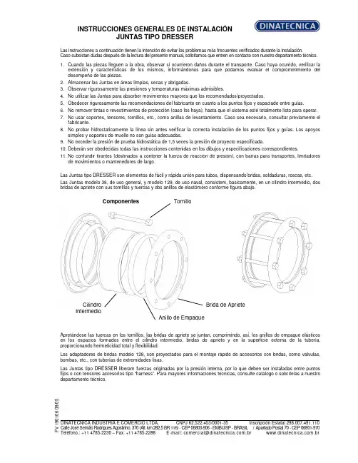
INSTRUCCIONES GENERALES DE INSTALACIÓN JUNTAS TIPO DRESSERLas instrucciones a continuación tienen la intención de evitar los problemas más frecuentes verificados durante la instalación. Caso subsistan dudas después de la lectura del presente manual, solicitamos que entren en contacto con nuestro departamento técnico.1. Cuando las piezas lleguen a la obra, observar si ocurrieron daños durante el transporte. Caso haya ocurrido, verificar la extensión y características de los mismos, informándonos para que podamos evaluar el comprometimiento del desempeño de las piezas.2. Almacenar las Juntas en áreas limpias, secas y abrigadas.3. Observar rigurosamente las presiones y temperaturas máximas admisibles.4. No utilizar las Juntas para absorber movimientos mayores que los recomendados/proyectados.5. Obedecer rigurosamente las recomendaciones del fabricante en cuanto a los puntos fijos y espaciado entre guías.6. No remover tintas o revestimientos de protección (caso los haya), hasta que el sistema esté totalmente listo para operar.7. No usar soportes, tensores, tornillos, etc., como anillas de levantamiento. Caso sea necesario, consultar previamente el fabricante.8. No probar hidrostaticamente la línea sin antes verificar la correcta instalación de los puntos fijos y guías. Los apoyos simples y soportes de muelle no son guías adecuadas.9. No exceder la presión de prueba hidrostática de 1,5 veces la presión de proyecto especificada.10. Deberán ser obedecidas todas las instrucciones contenidas en los dibujos y especificaciones correspondientes.11. No confundir tirantes (destinados a contener la fuerza de reacción de presión), con barras para transportes, limitadores de movimientos o mantenedores de largo.Las Juntas tipo DRESSER son elementos de fácil y rápida unión para tubos, dispensando bridas, soldaduras, roscas, etc. Las Juntas modelo 38, de uso general, y modelo 129, de uso naval, consistem, basicamente, en un cilindro intermedio, dos bridas de apriete con sus tornillos y tuercas y dos anillos de elastómero conforme figura abajo.Componentes Apretándose las tuercas en los tornillos, las bridas de apriete se juntan, comprimindo, así, los anillos de empaque elásticos en los espacios formados entre el cilindro intermedio, bridas de apriete y en la superficie externa de la tubería, proporcionando hermeticidad total y flexibilidad.Los adaptadores de bridas modelo 128, son proyectados para el montaje rápido de accesorios con bridas, como válvulas, bombas, etc., con tuberías de extremidades lisas.Las Juntas tipo DRESSER liberam fuerzas originadas por la presión interna, por lo que deben ser instaladas entre puntos fijos o con tensores accesorios tipo “harness”. Para mayores informaciones técnicas, consulte catálogo o solicítelas a nuestro departamento técnico.F V 190106 08/05 DINATECNICA INDUSTRIA E COMERCIO LTDA. CNPJ 62.522.453/0001-35 Inscripción Estatal 298.007.491.110 Calle José Semião Rodrigues Agostinho, 370 (Alt. km 282,5 BR 116) - CEP 06803-906 - EMBU/SP - BRASIL / Apartado Postal 70 - CEP 06801-970Teléfono.: +11 4785-2230 – Fax: +11 4785-2288 E-mail:*************************.br .brTornilloBrida de Apriete Anillo de EmpaqueCilindro IntermedioINSTRUCCIONES GENERALES DE INSTALACIÓN JUNTAS TIPO DRESSERTipos 38 y 129 ESQUEMA DE MONTAJELimpiar los extremos de los tubos que serán acoplados (aprox.200 mm en cada extremo). Remover completamente cualesquiera oleosidades, rebarbas, salpicaduras de soldadura, etc., de tal forma que los tubos queden limpios y sin ningún saliente que pueda perjudicar el montaje y performance de la Junta. Recomendamos que, después de limpiar los anillos de empaque y, antes del montaje del sistema, sean imersos en una solución de água y jabón (y glicerina, tratándose de temperaturas abajo de 0°C), lo que facilitará el montaje de los mismos.Colocar las bridas de apriete, deslizándolas en el área limpia de los tubos. Posicionar los anillos de empaque cerca de las bridas (uno en cada extremo del tubo).Limpiar bien el cilindro intermedio, poniendo particular atención en los extremos donde asentarán los anillos de empaque. Colocar el cilindro intermedio sobre uno de los tubos terminales.Aproximar el otro terminal hasta conseguir que entre los dos extremos se establezca una holgura de 13mm (tipo 38), y de 13 mm + diámetro del “pipe-stop” (tipo 129). Esta holgura permite la absorción de la dilatación de la línea.Una vez completada la centralización, deslize los anillos de empaque y bridas de apriete contra los extremos (asientos) del cilindro intermedio hasta que se produzca el encaje de los mismos.Insertar los tornillos. Ajustar las tuercas manualmente hasta que se recuesten en las bridas.El apriete final deberá ser dado con dos llaves fijas, una produciendo el torque y otra impidiendo el giro del tornillo.El apriete deberá ser realizado en forma intercalada con fuerza progresiva, hasta conseguir que todos los tornillos tengan un ajuste uniforme. Si en la prueba hidrostática surgiesen escapes, deberá darse un sobre-apriete uniforme, progresivamente, hasta que la prueba presente resultado satisfatório.Cuando haya “pipe-stops”, estos deberán ser retirados antes de la instalación y recolocados después de su finalización.Tipo 128 Deben seguirse los mismos cuidados para los tipos 38 y 129, sin embargo, considerándose que uno de los terminales es parte integrante de la Junta, lo que facilitará su instalación.a) Antes de, eventualmente, modificar cualesquiera de nuestras instrucciones, solicitamos consultarnos. NOTAS: b) Nuestra garantía no cubre daños ocurridos por el incumplimiento de cualesquiera de las recomendaciones aquí expuestas, sin nuestro previo consentimiento.F V 190106 08/05DINATECNICA INDUSTRIA E COMERCIO LTDA. CNPJ 62.522.453/0001-35 Inscripción Estatal 298.007.491.110 Calle José Semião Rodrigues Agostinho, 370 (Alt. km 282,5 BR 116) - CEP 06803-906 - EMBU/SP - BRASIL / Apartado Postal 70 - CEP 06801-970Teléfono.: +11 4785-2230 – Fax: +11 4785-2288 E-mail:*************************.br .br。
EN 60204-1机械电气系统安全需求旸致科技股份有限公司Sunreach Technology Co., Ltd. TEL:(04)24758336 FAX:(04)24758230目录第5章电源入线及切断装置 (4)5.1节电源入线 (4)5.2节外部接地系统 (4)5.3节电源断电装置 (4)5.4节防意外起动之切断装置 (5)5.5节个别电气设备的断电装置 (5)5.6节未经授权、意外及/或错误开启的保护 (5)第六章触电保护 (6)6.2节直接触电保护 (6)6.3节间接触电保护 (7)6.4节超低压保护(PELV) (7)第七章设备的保护 (7)7.2节过电流保护 (7)7.3节马达的过载保护 (8)7.4节异常温度 (8)7.5节电源中断或电压降低与随后电力恢复的保护 (8)7.6节马达过速度保护 (8)7.7节接地失效/残余电流保护 (8)7.8节相序保护 (8)7.9节因闪电及开关涌流而造成过电压的保护 (9)第八章等电位键结 (9)8.2节保护性键结电路 (9)第九章控制电路与控制功能 (10)9.1节控制电路电源 (10)9.2节控制功能 (10)9.3节保护互锁 (12)9.4节绝缘失效时的控制功能 (13)第十章操作者接口与机器外部之控制装置 (13)10.1节安装与位置 (13)10.2节按钮开关 (14)10.3节指示灯及显示 (14)10.4节照光式按钮开关 (14)10.5节旋转式控制装置 (15)10.6节启动装置 (15)10.7节紧急停止装置 (15)10.8节紧急切断装置 (15)10.9节显示装置 (15)11.2节基本需求 (15)11.3节可程序设备 (16)第十二章控制机构: 位置,安装与电气箱 (16)12.1节一般需求 (16)12.2节位置与安装 (16)12.3节保护等级 (17)12.4节电气箱,门及开孔 (17)12.5节控制机构的接近 (18)第十三章导线与电缆线 (18)13.2节导线 (18)13.3节绝缘 (18)13.4节电流承载量 (18)13.5节导线与电缆线电压降 (18)13.6节最小线径需求 (19)13.7节可挠性电缆线 (19)13.8节集电线、集电条与集电环组合 (19)第十四章配线实务 (20)14.1节连接与线路 (20)14.2节导线的辨认 (20)14.3节电气箱内配线 (21)14.4节电气箱外配线 (21)14.5节导线槽,接线盒及其它接线箱 (22)第十五章电动马达与相关设备 (23)15.1节一般需求 (23)15.2节马达外壳 (24)15.3节马达尺寸 (24)15.4节马达安装与隔间 (24)15.5节马达选用的准则 (24)15.6节机械性煞车保护装置 (25)第十六章附属设备及照明 (25)16.1节附属设备 (25)16.2节机器与设备的局部照明 (25)第十七章标志,警告标示及参考名称 (26)17.1 节一般需求 (26)17.2 节警告标示 (26)17.3 节功能辨认 (26)17.4 节控制设备的标示 (26)17.5 节参考名称 (27)18.1节一般通则 (27)18.2节须提供的数据 (27)18.3节文件需求 (27)18.4节基本数据 (27)18.5节安装图 (28)18.6节方块(系统)图与功能图 (28)18.7节电路图 (28)18.8节操作手册 (28)18.9节维修手册 (28)18.10节组件表 (28)第十九章测试与检查 (28)19.1 节一般需求 (29)19.2 节保护性键结电路的连续性 (29)19.3 节绝缘电阻测试 (29)19.4 节耐压测试 (30)19.5 节残存电压防护 (30)19.6 节功能性测试 (30)19.7 节重测 (30)附录一: 何谓IP保护等级 (31)附录二: 导线的等级 (31)第5章电源入线及切断装置5.1节电源入线1. 建议机器电控系统的电源供给为单一电源。
![变速箱维修拆装 伊顿[上海]S9和S13挡变速箱维修工具操作手册](https://uimg.taocdn.com/768e7cffaeaad1f346933f6b.webp)
EUxComfort CDAU-01/02, CDAU-01/03Assembly instructionsMontageanweisungInstructions de montageMontážní návodMontážní návodMontagevejledningInstrucciones de montajeSzerelési utasitásIstruzioni di montaggioMontasjeveiledningMontage instructieInstruções de montagemInstrukcja montazuMontageanvisningAsennusohjeetMontaj talimatiInstructiuni de montajDangerLebensgefahrDanger de mortNebezpeíčNebezpe enstvočFarePeligroÉletveszélyPericolo di morteFareLevensgevaarPerigoNiebezpieczenstwoVarningVaaraHayati TehlikePericolInstallation by electricians onlyMontage nur durch ElektrofachkräfteMontage uniquement par un électricienMontážpouze osobami s elektrotechnickou kvalifikaciMontážiba osobami s elektrotechnickou kvalifikáciouM kun installeres af en aut. el-installatøråDebe ser instalado por un profesional eléctricoCsak szakképzett személy szerelhetiMontaggio esclusivamente ad opera di personale specializzatoM monteres av autorisert installatøråMontage alleen door elektromonteursDeve ser instalado por um profissionalMontaz tylko przez uprawnionych instalatorówF r endast utföras av behörig elektrikeråAsennus vain sähköasentajan toimestaSadece uzman kisiler monte edebilirInstalare numai de catre electricieniIP20CDAU-01/02EU- type examination performed by:TÜV Austria Services GmbH, Notified Body 1230 Vienna, Deutschstrasse 10, AustriaAffixing date of CE mark: 2003Doc.Id.: CDAU-0102_CDAU-0103_171117Senior Vice President Director Quality General Manager & SystemsFriedrich Schröder Fernando CeccarelliWe, EATON Industries (Austria) GmbH 3943 Schrems, Eugenia 1 Austriadeclare under our sole responsibility that the product (family)Eaton - Dimming actuator, CDAU-01/02; CDAU-01/03(the declaration of conformity applies to alllisted types within our actual product catalogue)provided that it is installed, maintained and used in theapplication intended for, with respect to the relevant manufacturers instructions, installation standards and “good engineering practices”complies with the provisions of Council directive(s):RED Directive 2014/53/EURoHS Directive 2011/65/EUbased on compliance with following standard(s):EN 301489-3 V2.1.1, EN 300220-2 V3.1.1, EN 50491-5-1:2010,EN 50491-5-2:2010, EN 62479:2010, EN 55015:2013, EN 61547:2009, EN 50428:2005 + A1:2007 + A2:2009, EN 50581:201217.11.2017。
Keep your customers on the road.Eaton’s complete portfolio of all-makes transmission parts are available for popular automated manual transmissions (AMTs), including Detroit™ DT12®, Volvo ® I-Shift and Mack ®mDRIVE™. Premium components ensure quality and fit, and are backed by Eaton quality and support.This comprehensive line of service parts includes everything needed for a complete remanufactured transmission unit including gears, bearings, gaskets, shafts, synchronizers and fasteners, so you can get your customer's trucks back on the road quickly. Eaton recommends replacing all wearable parts when performing service to maximize uptime and reliability.S U P P O R T B A C K E D B YFor spec’ing or service assistance, call 1-800-826-HELP (4357) or visit . Eaton Vehicle Group 13100 E. Michigan Ave.Kalamazoo, MI 49053 USA© 2022 Eaton All Rights Reserved. Printed in USA.APSL0701 0122Note: Features and specifications listed in this document are subject to change without notice. Although every attempt has been made to ensure the accuracy of information contained within, Eaton makes no representation about the completeness, correctness or accuracy and assumes no responsibility for any errors or omissions. Features and functionality may vary depending on selected options.Eaton and Roadranger are registered trademarks of Eaton. All trademarks, logos and copyrights are those of their respectiveowners.Core Features:•Premium components ensure quality and fit: fully interchangeable with original parts • Complete range of components:over 400 parts for DT12, I-Shift and mDRIVE AMTs • Simple ordering: convenient kits include all recommended service replacement parts in one part number • Fully backed by Eaton quality and support • Quick delivery: all inventory stocked in Eaton USwarehouse。
C lutch Division, Eaton Corporation伊顿430mm拉式膜片离合器(快速连接分离轴承)EATON 430mm Pull Clutch (Quick Attached Release Bearing)安装拆卸指导Installation Guide伊顿卡车客车零部件(上海)有限公司EATON TRUCK & BUS COMPONENTS(SHANGHAI) CO., LTD.2009-9-18 修订1. 测量测量发动机飞轮壳和飞轮。
发动机飞轮壳和飞轮必须满足以下技术要求,否则将导致离合器的早期磨损,取下旧的导向轴承,所有被测量面必须擦拭干净,保持干燥。
使用百分表检查以下部位:1.飞轮面端面跳动: 将百分表座可靠的固定在飞轮壳端面,百分表触头垂直接触飞轮面靠外圈部位,旋转飞轮一周,最大的跳动量为0.20mm2. 导向轴承内孔圆跳动继续以上测量,百分表触头移至导向轴承安装孔内表面,旋转飞轮一周,最大圆跳动为0.13mm3.飞轮壳内径圆跳动 将百分表表座可靠的固定在曲轴上,百分表触头接触飞轮壳导向内孔面上,旋转飞轮一周,最大跳动量为0.20mm4.飞轮壳定位端面跳动将百分表表座可靠的固定在曲轴上,百分表触头接触飞轮壳定位端面上,旋转飞轮一周,最大跳动量为0.20mm注:在样车试制中,这一步必须做。
在量产中,可以省略,但需要视觉检查配合面质量,并定时抽检。
2 离合器安装第一步:擦净飞轮表面的油泥、润滑脂或防锈油等第二步:测量飞轮沉孔尺寸是否与从动盘减振器相配第三步:检查在飞轮上是否正确安装了新的导向轴承。
第四步:安装两个导向螺柱到飞轮的11和1点钟的位置上。
如下面左边图示。
根据安装熟练程度,可以省去导向螺栓的安装。
第五步:将导向花键穿过离合器盖和离合器从动盘。
确保从动盘上标有“Flywheel Side”面朝向飞轮。
第六步:将导向花键轴带着盖总成和从动盘插入飞轮上的导向轴承,然后将盖总成对准两个导向螺柱,安装到飞轮上。