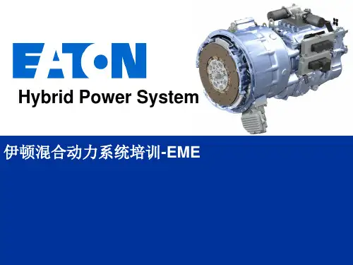
Eaton Hybrid General Introduction-JH
- 格式:pdf
- 大小:661.26 KB
- 文档页数:15
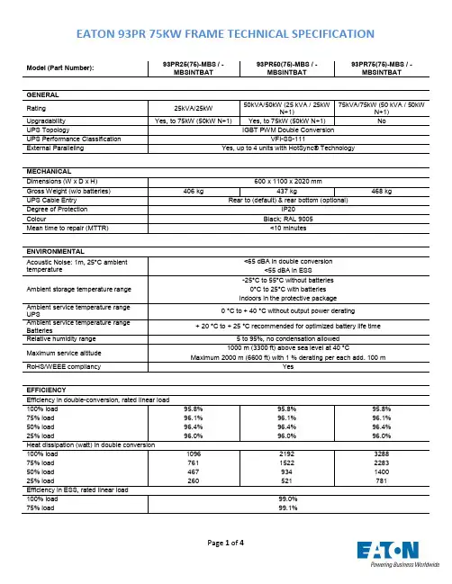
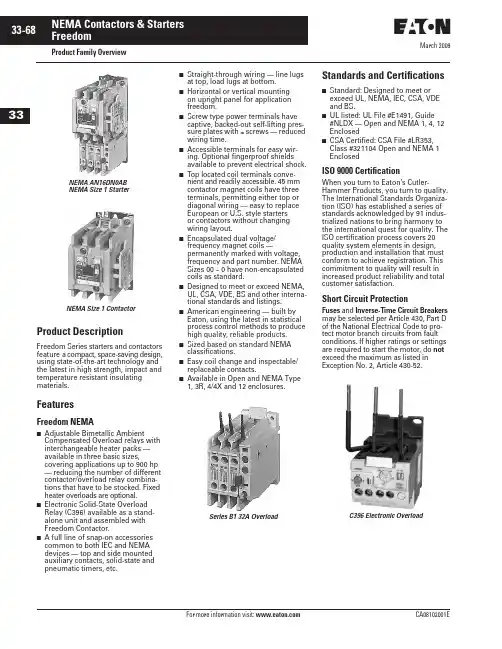
March 2009Product Family OverviewProduct DescriptionFreedom Series starters and contactors feature a compact, space-saving design, using state-of-the-art technology and the latest in high strength, impact and temperature resistant insulating materials.FeaturesFreedom NEMA■Adjustable Bimetallic AmbientCompensated Overload relays with interchangeable heater packs — available in three basic sizes,covering applications up to 900 hp — reducing the number of different contactor/overload relay combina-tions that have to be stocked. Fixed heater overloads are optional.■Electronic Solid-State Overload Relay (C396) available as a stand-alone unit and assembled with Freedom Contactor.■ A full line of snap-on accessories common to both IEC and NEMA devices — top and side mounted auxiliary contacts, solid-state and pneumatic timers, etc.■Straight-through wiring — line lugs at top, load lugs at bottom.■Horizontal or vertical mounting on upright panel for application freedom.■Screw type power terminals have captive, backed-out self-lifting pres-sure plates with ± screws — reduced wiring time.■Accessible terminals for easy wir-ing. Optional fingerproof shields available to prevent electrical shock.■Top located coil terminals conve-nient and readily accessible. 45 mm contactor magnet coils have three terminals, permitting either top or diagonal wiring — easy to replace European or U.S. style starters or contactors without changing wiring layout.■Encapsulated dual voltage/frequency magnet coils —permanently marked with voltage, frequency and part number. NEMA Sizes 00 – 0 have non-encapsulated coils as standard.■Designed to meet or exceed NEMA, UL, CSA, VDE, BS and other interna-tional standards and listings.■American engineering — built by Eaton, using the latest in statistical process control methods to produce high quality, reliable products.■Sized based on standard NEMA classifications.■Easy coil change and inspectable/replaceable contacts.■Available in Open and NEMA Type 1, 3R, 4/4X and 12 enclosures.Standards and Certifications■Standard: Designed to meet or exceed UL, NEMA, IEC, CSA, VDE and BS.■UL listed: UL File #E1491, Guide #NLDX — Open and NEMA 1, 4, 12 Enclosed■CSA Certified: CSA File #LR353, Class #321104 Open and NEMA 1 EnclosedISO 9000 CertificationWhen you turn to Eaton’s Cutler-Hammer Products, you turn to quality. The International Standards Organiza-tion (ISO) has established a series of standards acknowledged by 91 indus-trialized nations to bring harmony to the international quest for quality. The ISO certification process covers 20 quality system elements in design, production and installation that must conform to achieve registration. This commitment to quality will result in increased product reliability and total customer satisfaction.Short Circuit ProtectionFuses and Inverse-Time Circuit Breakers may be selected per Article 430, Part D of the National Electrical Code to pro-tect motor branch circuits from fault conditions. If higher ratings or settings are required to start the motor, do not exceed the maximum as listed in Exception No. 2, Article 430-52.NEMA AN16DN0AB NEMA Size 1 StarterNEMA Size 1 ContactorSeries B1 32A OverloadC396 Electronic OverloadMarch 2009Starters — 3-Phase Non-reversing and Reversing, Full VoltageContentsDescriptionPageProduct Family OverviewProduct Description. . . . . . 33-68Features . . . . . . . . . . . . . . . 33-68Standards andCertifications . . . . . . . . . . 33-68Catalog NumberSelection . . . . . . . . . . . . . 33-69Starters — 3-Phase Non-reversing and Reversing, Full Voltage, Bi-Metallic OverloadProduct Description. . . . . . 33-73Features . . . . . . . . . . . . . . . 33-73Technical Data . . . . . . . . . . 33-74Wiring Diagrams . . . . . . . . 33-74Product Selection. . . . . . . . 33-75Starters — 3-Phase Multispeed, Bi-Metallic OverloadProduct Selection. . . . . . . . 33-76Starters — Single-PhaseNon-reversing, Full Voltage, Bi-Metallic OverloadProduct Description. . . . . . 33-77Wiring Diagrams . . . . . . . . 33-77Product Selection. . . . . . . . 33-77Starters — 3-Phase Non-reversing and Reversing, Full Voltage,C386 Electronic Overload . . 33-78Technical Data . . . . . . . . . . . . . 33-79Accessories . . . . . . . . . . . . . . . 33-82Auxiliary Contacts . . . . . . . 33-86DC Magnet Coils . . . . . . . . 33-88Mounting Plates. . . . . . . . . 33-89Special Modifications . . . . . . . 33-90Renewal Parts . . . . . . . . . . . . 33-91Dimensions . . . . . . . . . . . . . . . 33-94Product DescriptionNon-reversingThree-phase, full voltage magnetic starters are most commonly used to switch AC motor loads. Starters con-sist of a magnetically actuated switch (contactor) and an overload relay assembled together.ReversingThree-phase, full voltage magnetic starters are used primarily for revers-ing of 3-phase squirrel cage motors. They consist of two contactors and a single overload relay assembledtogether. The contactors are mechani-cally and electrically interlocked to prevent line shorts and energization of both contactors simultaneously.Features■Bimetallic Ambient Compensated Overload relays — available in three basic sizes covering applications up to 900 hp — reducing number of different contactor/overload relay combinations that have to be stocked.These overload relays feature:❑Selectable Manual or Automatic Reset operation.❑Interchangeable heater packs adjustable ±24% to match motor FLA and calibrated for 1.0 and 1.15 service factors. Heater packs for smaller overload relay will mount in larger overload relay — useful in derating applications such as jogging.❑Load lugs built into relay base.❑Single-phase protection, Class 20 or Class 10 trip time.❑Overload trip indication.❑Electrically isolated NO-NC con-tacts (pull RESET button to test).■The C396 is a self-powered, robust electronic overload designed for integrate use with Freedom NEMA contactors.❑Tiered feature set to provide cov-erage specific to your application.❑Broad 5:1 FLA range for maxi-mum flexibility.❑Coverage from 0.05 – 1500 Amps to meet all your needs.■Long life twin break, silver cadmium oxide contacts — provide excellent conductivity and superior resistance to welding and arc erosion. Gener-ously sized for low resistance and cool operation.■Designed to 3,000,000 electrical operations at maximum hp ratings up through 25 hp at 600V.■Steel mounting plate standard on all open type starters.■Wired for separate or common control.Non-reversing■Holding circuit contact(s) supplied as standard:❑Sizes 00 – 3 have a NO auxiliary contact block mounted on right-hand side (on Size 00, contact occupies 4th power pole position — no increase in width).❑Sizes 4 – 5 have a NO contact block mounted on left side.❑Sizes 6 – 7 have a 2NO/2NC contact block on top left.❑Size 8 has a NO/NC contact block on top left back and a NO on top right back.Reversing■Each contactor (Size 00 – 8) supplied with one NO-NC sidemounted contact block as standard. NC contacts are wired as electrical interlocks.NEMA Size 1 — Cat. No. AN16DN0ABNEMA Size 1 — Cat. No. AN56DN0ABMarch 2009Starters — 3-Phase Non-reversing and Reversing, Full VoltageTechnical DataTable 33-96. Wire (75°C) Sizes — AWG or kcmil — NEMA Sizes 00 – 2 — Open and EnclosedᕃTwo compartment box lug.ᕄMinimum per NEC. Maximum wire size: Sizes 00 and 0 to 8 AWG and Sizes 1 – 2 to 2 AWG.Table 33-97. Wire (75°C) Sizes — AWG or kcmil — NEMA Sizes 3 – 8 — Open and EnclosedᕅMinimum per NEC. Maximum wire size: Sizes 00 and 0 to 8 AWG and Sizes 1 – 2 to 2 AWG.Wiring DiagramsFigure 33-24. Typical Wiring Diagrams — Three-Phase and Single-Phase ApplicationsNEMA SizeWire Size ᕄ Cu OnlyPower Terminals — Line0001212 – 16 AWG stranded, 12 – 14 AWG solid 8 – 16 AWG stranded, 10 – 14 AWG solid 8 – 14 AWG stranded or solid3 – 14 AWG (upper) and/or 6 – 14 AWG (lower) stranded or solid ᕃPower Terminals — Load — Cu Only (stranded or solid)00 – 01 – 214 – 6 AWG stranded or solid 14 – 2 AWG stranded or solidControl Terminals — Cu Only12 – 16 AWG stranded, 12 – 14 AWG solidNEMA SizeWire Size ᕅPower Terminals — Line and Load31/0 – 14 AWG Cu/Al4Open — 3/0 – 8 AWG Cu; Enclosed — 250 kcmil — 6 AWG Cu/Al 5678750 kcmil — 2 AWG; or (2) 250 kcmil — 3/0 AWG Cu/Al (2) 750 kcmil — 3/0 AWG Cu/Al (3) 750 kcmil — 3/0 AWG Cu/Al (4) 750 kcmil — 1/0 AWG Cu/AlControl Terminals — Cu Only12 – 16 AWG stranded, 12 – 14 AWG solidTable 33-98. Plugging and Jogging Service Horsepower Ratings ᕆᕆMaximum horsepower where operation is interrupted more than 5 times per minute, or more than 10 times in a 10 minute period. NEMA Standard ICS2-1993 table 2-4-3.Kits and Accessories■Auxiliary Contacts, contactor mounted — Pages 33-86 – 33-87. ■Transient Suppressor, for magnet coil — Pages 33-84.■Timers — Solid-State andPneumatic, mount on contactor — Page 33-83.Renewal Parts Publication Numbers■See Page 33-91.NEMA Size 200V 230V 460V 575V 000123—1-1/237-1/2151/21-1/2310201/22515301/2251530456256012530751506015030060150300March 2009Starters — 3-Phase Non-reversing and Reversing, Full Voltage, Bi-Metallic OverloadProduct SelectionWhen Ordering Supply■Catalog Number■Heater pack number (see selectiontable, Pages 33-107 – 33-108) or full load current.Table 33-99. Type AN16/AN56 NEMA — Manual or Automatic Reset Overload Relay — Non-reversing and ReversingNote: Starter Catalog Numbers do not include heater packs. Select one carton of three heater packs. Heater pack selection, Pages 33-107 – 33-108.ᕃUnderscore (_) indicates coil suffix required, see Table 33-100.ᕄMaximum horsepower rating of starters for 380V 50 Hz applications: ᕅThe service-limit current ratings represent the maximum rms current, in amperes, which the controller shall be permitted to carry for protracted periods in normal service. At service-limit current ratings, temperature rises shall be permitted to exceed those obtained by testing the controller at itscontinuous current rating. The current rating of overload relays or trip current of other motor protective devices used shall not exceed the service-limit current rating of the controller.ᕆCommon control. For separate 120V control, insert letter D in 7th position of listed Catalog Number. EXAMPLE: AN56VN D 0CB.Magnet Coils — AC or DCStarter coils listed in this section also have a 50 Hz rating as shown in the adjacent table. Select required starter by Catalog Number and replace the magnet coil alpha designation in the Catalog Number (_) with the proper Code Suffix from the adjacent table.For Sizes 00 – 2 and 5 – 8, the magnet coil alpha designation will be the next to last digit of the listed Catalog Num-ber. EXAMPLE: For a 380V, 50 Hz coil, change AN16BN0_C to AN16BN0L C. For all other sizes, the magnet coil alpha designation will be the last digit of the listed Catalog Number.For DC Magnet Coils , see Accessories, Pages 33-88 – 33-89.Table 33-100. AC Suffix CodeᕇNEMA Sizes 00 and 0 only.ᕈNEMA Sizes 00 and 0 only. Sizes 1 – 8 are 24/60 only.NEMA Size Continuous Ampere Rating Service-Limit CurrentRating ᕅ(Amperes)Maximum UL Horsepower ᕄ3-PoleNon-reversing ᕃ3-PoleReversing ᕃVerticalReversing ᕃPrice U.S. $1-Phase3-Phase115V 230V 208V 240V 480V 600V CatalogNumber Price U.S. $Catalog Number Catalog Number 009111/311-1/21-1/222AN16AN0_C AN56AN0_C —01821123355AN16BN0_C AN56BN0_C AN56BNV0_12732237-1/27-1/21010AN16DN0_B AN56DN0_B AN56DNV0_2455237-1/210152525AN16GN0_B AN56GN0_B AN56GNV0_390104——25305050AN16KN0_AN56KN0_AN56KNV0_4135156——4050100100AN16NN0_AN56NN0_AN56NNV0_5270311——75100200200AN16SN0_B AN56SN0_B —6540621——150200400400AN16TN0_C AN56TN0_C —7810932——200300600600AN16UN0_B AN56UN0_B —8 ᕆ12151400——400450900900AN16VN0_BAN56VN0_B—NEMA Size 00012345678Horsepower1-1/2510255075150300600900Size 0Non-reversing StarterSize 1Reversing StarterSize 3 Vertical Reversing StarterNEMA Size 0Cat. No. AN56BN0ACCoil Volts and Hertz Code Suffix 120/60 or 110/50240/60 or 220/50480/60 or 440/50600/60 or 550/50A B C D 208/60277/60208 – 240/60 ᕇ240/50E H J K 380 – 415/50550/5024/60, 24/50 ᕈ24/50L N T U 32/5048/6048/50V W YTechnical Data. . . . . . . . . . Pages 33-79 – 33-81Overload Relay . . . . . . . . . Page 33-103Dimensions . . . . . . . . . . . . Pages 33-96 – 33-98Special Modifications . . . Page 33-90Accessories. . . . . . . . . . . . Pages 33-82 – 33-90March 2009Starters — Single-Phase Non-reversing, Full Voltage, Bi-Metallic OverloadProduct DescriptionSingle-phase, full voltage magnetic starters connect the motor directly across the line, allowing it to draw full inrush current during start-up. These starters are most commonly used for control of self-starting single-phase motors up to 15 horsepower at 230V. They consist of a 2-pole electromag-netic contactor to make and break the motor power circuit and an overload relay to provide running overload protec-tion. Starters listed in the table include:■Two-pole Freedom Series contactor with long life twin break, silver cadmium oxide contacts. Generously sized for low resistance and cool operation. Designed to 3 mil-lion electrical operations at maximum hp and 30 million mechanical operations to Size 0, 10 million operations to Size 2 and 6 million operations to Size 3.■Three-pole Freedom Series overload with poles 2 and 3 wired in series for motor overload protection. This over-load is ambient compensated, selectable Manual or Auto-matic reset, interchangeable Class 10 or 20 heater packs, 1.0 or 1.15 service factor selectability, overload trip indica-tion and electrically isolated NO-NC contacts (pull RESET button to test).■Holding circuit NO auxiliary contact supplied as standard. On Size 00, the contact occupies the 4th power pole position. Sizes 0 – 3 have the NO auxiliary mounted on the right side of the contactor.■Steel mounting plate as standard on all open type starters. Wired for separate or common control.Wiring DiagramsFigure 33-25. Typical Wiring Diagrams — Single-Phase Applications (Factory Wired)Product SelectionWhen Ordering Specify■Catalog Number■Heater Pack Number (see selection table, Pages 33-107 – 33-108) or full load current.Table 33-104. Type BN16 NEMA — Manual or Automatic Reset Overload RelayNote: Starter Catalog Numbers do not include heater packs. Select 1 carton of 3 heater packs. Heater pack selection, Pages 33-107 – 33-108.ᕃFor separate 120V control circuit. For maximum hp at listed motor voltages, use the rating of other starters of same size.NEMA Size 1 — Cat. No. BN16DN0ABNEMA SizeMaximum Horsepower MagnetCoil Voltage (60 Hz)Open Type 2-Pole Motor Voltage 1-Phase Catalog Number Price U.S. $001152301/31120 ᕃ240BN16AN0AC BN16AN0BC 011523012120 ᕃ240BN16BN0AC BN16BN0BC 111523023120 ᕃ240BN16DN0AB BN16DN0BB 1P 11523035120 ᕃ240BN16PN0AB BN16PN0BB 211523037-1/2120 ᕃ240BN16GN0AB BN16GN0BB 31152307-1/215120 ᕃ240BN16KN0A BN16KN0BContentsDescriptionPage Thermal Overload RelaysProduct Description. . . . . . 33-103Features . . . . . . . . . . . . . . . 33-103Operation . . . . . . . . . . . . . . 33-103Technical Information . . . . 33-103Technical Data . . . . . . . . . . 33-104Factory Modifications . . . . 33-105Accessories. . . . . . . . . . . . . 33-105Replacement Parts. . . . . . . 33-105Dimensions. . . . . . . . . . . . . 33-106Product Selection. . . . . . . . 33-107Heater Pack Selection . . . .33-107Product DescriptionC306 Overload Relays are designed for use with CE or CN non-reversing and reversing contactors. Four sizes are available for overload protection up to 144A.Features■Selectable Manual or Automatic Reset operation.■Interchangeable Heater Packs adjustable ±24% to match motor FLA and calibrated for use with 1.0 and 1.15 service factor motors.Heater packs for 32A overload relay will mount in 75A overload relay — useful in derating applications such as jogging.■Class 10 or 20 heater packs.■Load lugs built into relay base.■Bimetallic, ambient compensated operated. Trip free mechanism.■Electrically isolated NO-NC contacts (pull RESET button to test).(Electrical Ratings see Table 33-158 on Page 33-104).■Shrouded or fingerproof terminals to reduce possibility of electrical shock.■Meets UL 508 single-phasing requirements.■UL listed, CSA certified, NEMA compliance and CE mark.OperationC306 Overload Relay SettingFigure 33-43. FLA Dial AdjustmentFor motors having a 1.15 service fac-tor, rotate the FLA adjustment dial to correspond to the motor’s FLA rating. Estimate the dial position when the motor FLA falls between two letter values as shown in the example.For motors having a 1.0 service factor, rotate the FLA dial one-half position counterclockwise (CCW).Figure 33-44. Manual/Automatic Reset The overload relay is factory set at M for manual reset operation. For auto-matic reset operation, turn the reset adjustment dial to the A position as shown in the illustration.Automatic reset is not intended for two-wire control devices.Test for Trip IndicationTo test overload relay for trip indica-tion when in manual reset, pull out the blue reset button. An orange flag will appear indicating that the device has tripped. Push reset button in to reset.Warning — To provide continued pro-tection against fire or shock hazard, the complete overload relay must be replaced if burnout of the heater element occurs.Technical InformationGeneral“Overload relays are provided to pro-tect motors, motor control apparatus and motor-branch circuit conductors against excessive heating due to motor overloads and failure to start. This definition does not include:1) motor circuits over 600V,2) short circuits,3) ground faults and 4) fire pump control.” (NEC Art. 430-31)Time Current CharacteristicsThe time-current characteristics of an overload relay is an expression of per-formance which defines its operating time at various multiples of its current setting. Tests are run at Underwriters Laboratories (UL) in accordance with NEMA Standards and the NEC. UL requires:■When tested at 100 percent of its current rating, the overload relay shall trip ultimately.■When tested at 200 percent of its current rating, the overload relay shall trip in not more than 8 minutes.■When tested at 600 percent of the current rating, the overload relay shall trip in not more than 10 or 20 seconds, depending on the Class of the relay.“Current Rating” is defined as the minimum current at which the relay will trip. Per NEC, an overload must ultimately trip at 125% of FLA current (heater) setting for a 1.15 service factor motor and 115% FLA for a 1.0 service factor motor.“Current Setting” is defined as the FLA (Full Load Amperes) of the motor and thus the overload heater pack setting.Example: 600% of current rating is defined as 750% (600 x 1.25) of FLA current (heater) setting for a 1.15 ser-vice factor motor. A 10A heater setting must trip in 20 seconds or less at 75A 32A OverloadCat. No. C306DN3BProduct SelectionTable 33-166. C306 Thermal Overload RelaysᕃNEMA Sizes 5 – 8 use the 32A overload in conjunction with CTs.ᕄSeries B overload relays have load lugs built into relay base and will only accept Series B heater packs. These relays can be directly attached to contactor or they can be DIN rail or panel mounted using adapter on Page 33-105.ᕅThese relays can be panel mounted only.Table 33-167. C306 Thermal Overload RelaysᕆOverload relay assembled with mounting adapter for DIN rail or panel mount.ᕇPanel mount only.ᕈNEMA Sizes 5 – 8 use the 32A overload in conjunction with CTs.Heater Pack SelectionHeater packs H2001B to H2017B and H2101B to H2117B are to be used only with Series B overload relays Catalog Numbers C306DN3B (Part No. 10-7016) and C306GN3B (Part No. 10-7020). The load lugs are built into the overload relay base to allow load wiring prior to heater pack installa-tion. The previous heater design had integral load lugs. The Series B heater packs are electrically equivalent to the previous heater design. Heaters H2018-3 to H2024-3 have not changed.Table 33-168. Starters with Series B Overload RelaysNote: The series of a starter is the last digit of the listed Catalog Number. EXAMPLE: AN16DN0A B .For Use with Freedom Series Contactors Maximum Ampere RatingNumber of PolesOpen Type NEMA 1 Enclosed NEMA Size Catalog NumberPrice U.S. $Catalog Number Price U.S. $00, 01, 2345 – 8 ᕃ32 ᕄ75 ᕄ105 ᕅ144 ᕅ—3333—C306DN3B C306GN3B C306KN3C306NN3—C306DG3B C306GG3B —75A OverloadCat. No. C306GN3B 75A OverloadCat. No. C306GT3B 32A OverloadCat. No. C306DT3B 32A OverloadCat. No. C306DN3BFor Stand-Alone Applications Maximum Ampere RatingNumber of PolesOpen Type NEMA Size Catalog NumberPrice U.S. $00, 0, 1 ᕆ1 ᕆ3 ᕇ4 ᕇ5 – 8 ᕈ3275105144—3333—C306DT3B C306GT3B C306KN3C306NN3—Heater PackH2001B – H2017BHeater PackH2101B – H2117BHeater Pack H2018 – H2024NEMA — AN Type IEC — AE Type Size Series Size Series 00 – 01 – 2567 – 8C B B C BA – F G – KC BTechnical Data . . . . . . . . Page 33-104Dimensions. . . . . . . . . . . . Page 33-106。

Distribution switchboardsThe broadest offering in the industryIndustry-leading Eaton switchboardsEaton’s electrical group offers the widest selection of switch-board types in the industry, and this is only the start.Our switchboards are built from the ground up based on customer input and needs. From the simplest 800A switchboard to Web-enabled, Eaton switchboards offer flexibility in designs to accommodate any power distribution need you have.Our flexible designs are onlyas good as the people andservice that bring the productsto you. Eaton has uniquelypositioned manufacturingcenters of excellencethroughout the United States.Our 18 facilities, strategicallylocated near our customers,provide more than just switch-boards and panelboards. Theyare your personal plants. TheseRegional Manufacturing Facilitieshave the capability of muchlarger facilities. They understandyour needs and your markets...because they are right there.Our goal, and the goal of ouroutstanding sales team, is toexceed your expectations.From emergency shipments tolarge projects, from new con-struction to aftermarket and ren-ovation, we have the experienceand expertise to help you.As you review the productsin this brochure, rememberthat this is only a samplingof our capabilities. To learn more,we invite you to contact yourlocal sales office or plant, andto come visit us.178429365Pow-R-Line C switchboardsEaton’s distributionswitchboards combine a space-saving design with modular construction and increased systems ratings to provide economical anddependable electrical system distribution and protection.Features•6000A maximum main bus rating • 600 Vac and below • Front or rear accessible • Indoor or outdoor enclosures •ANSI-61 gray powder coat paint finish•Microprocessor-based metering, monitoring and communication devices • Utility metering provisions •Surge protective devices (SPD)• Ground fault protection •Busway and transformer connections• Integrated panelboards (IFS E )•65 kAIC standard bus bracing; optional 100 or 200 kAIC •Aluminum or optional copper bus•Meets NEMA Standard PB-2 and UL 891•Seismically qualifiedMain devices•Magnum E DS power circuit breakers, 800–5000A • Molded-case circuit breakers, 400–2500A, fixed mounted •Pringle bolted pressure contact switches, 800–5000A •Fusible switches, 400–1200A1. Utility MeteringCompartmentsAvailable to meet standard or specific requirements. Units can be arranged for hot or cold sequence.2. Single Chassis DesignProvides device flexibility, accommodating both circuit breaker and fusible switches.3. Pow-R-Line C SwitchboardsGroup-mounted distribution switchboards.6. Electronic T rip Unit SystemAdvanced technology options offer superior protection, energy management and communications.7. Surge Protective DeviceIntegrally mounted with overcurrent feeder.Electronic trip unit systemEaton electronic trip units provide enhanced accuracy and reliability for protection and optimum system coordination.Surge protective devicesEaton’s surge protectivedevices (SPDs) protect sensitive electronic equipment from the damaging effects of high and low energy transients, as well as high-frequency noise.The SPD, combined with our innovative connection, yields the industry’s lowest let-through voltage.Wide range of surge ratings Surge current ratings from 100 to 400 kA per phaseprovide a range of cost-effective facility-wide protection solutions. Products are third-party tested to verify published surge current ratings.SPD mounted within the enclosure eliminates extra wiring and the need for outboard wall space:•UL 1449 Listed high-performance suppression system and parallel hybrid filter technology • Diagnostic system •Integral circuit breaker disconnect4. Eaton Molded-CaseCircuit Breakers 225A, electronic tripframe (left); 600A, electronic trip frame (middle); and 2500A, electronic trip frame (right).5. Magnum DS PowerCircuit Breakers8. Metering and MonitoringDevicesPower Xpert Gateway (front) and IQ 250 Meter (back).9. Eaton’s Power XpertCommunications System, Programming and Monitoring Accomplished remotely from a personal computer via the Web.Group-mounted distribution devices•Molded-case circuit breakers, 15–2000A•Fusible switches, 30–1200AMetering andmonitoring devicesA wide range of metering options for power measurement and power quality is available. Along with local display, these meters can provide Web-enabledmonitoring of Eaton switchboards and other equipment via an open communications architecture. The Power Xpert Gateway enables third-party equipment to communicate across this same system.DistributionswitchboardsIQ Energy SentinelsPower and energy information from IQ Sentinels can be communicated to a PC, a panel-mounted central energy display (CED), or even existing building management or distribution control systems.IQ Energy SentinelsCost-effectivesubmetering throughout the electrical systemThese devices monitor power and energy readings down to the smaller loads. They measure watts, peak demand andwatt-hours within a one-percent accuracy level.The device mounts directly on F-, J- or K-Frame feeder breakers without requiring additional panel height. A universal sentinel is available where breaker mounting is not feasible and for the larger frame breakers.162345Pow-R-Line i switchboardsPow-R-Line i distributionswitchboards are engineered in a compartmentalized design for applications where a greater degree of component isolation is required. A wide variety of configurations is possible, including utility metering, customer metering, main devices, branch devices, accessories and enclosures.Significant safety features•Individual compartments for branch devices help eliminate possible contact with the main bus and reduce fault propagation•Three-section construction with each barriered from the other:•Device section —each device is mounted in its own compartment•Busbar section —contains both horizontal and vertical busses•Rear cable compartment — completely isolated from the busbars•Insulated runbacks, so that power is taken from the protective device by the runback through a full-height glass-polyester barrier to the rear cable compartment, virtually eliminating the possibility of accidental contact with the main busses during installation or maintenanceConstruction features•Full family of metering and protective devices available •Custom-built utility metering compartments •Individually mounted main devices•Compartmentalized feeder devices•Meets NEMA Standard PB-2 and UL 891• Rear accessible•65 kAIC standard bus bracing; optional 100 and 200 kAIC •Aluminum or optional copper busbar •ANSI-61 gray powder coat paint finish •Indoor and outdoor enclosures•Seismically qualifiedA wide selection of branch devices Circuit breakersBranch circuit breakers range from 150A to 1200A Fusible switchesBranch fusible switches are avail-able from 100A to 1200A frames1. Branch Circuit BreakersShown in single- and tandem- mounted construction.2. Fusible SwitchesBranch fusible switches in single-unit construction.5. Laser Cut andPower Coat FinishLaser cut panelboard trims with a high-quality baked-on powder coat finish provides a high-quality appearance.6. Benefits of IFSIFS can be integrated with service equipment wherepanelboards are needed in the electrical distribution equipment room. IFS lowers installation time and saves space.Integrated facility systems (IFS)Eaton is the industry leader in integrated switchboards with more than 100,000 IFS sections delivered to customers. Eaton’s Integrated Facility Systems E (IFS) switchboards can reduce the overall space requirement over traditional panelboard and transformer installations. Because IFS is factory assembled and wired between major components, there are fewer pieces to handle and install, thus reducing installation time.IFS is ideal for both new construction and renovation. Each IFS switchboard is custom designed to meet customer requirements. Specificrequirements for panelboard configurations, as well as transformers and otherequipment, can be customized into IFS switchboards. Eaton’s experience andcapabilities ensure that your IFS is configured to yourexacting standards and delivered on time from one of Eaton’s 18 assembly plants.Standard panelboard andtransformer configurations can ship in as few as two weeks. These include IFS sections with 480Y/277 Vac lighting panelboards with a feeder to a NEMA TP1 transformerfeeding one or more 208Y/120 Vac panelboard(s). All breakers are installed to your drawings and factory wired between the transformer feeder device and the 208 Vac lighting panelboard.3. Pow-R-Line i SwitchboardsCompartmentalized design for increased device isolation.4. Barriered ConstructionOvercurrent devices isolated from bus.Features• Single - and three-phase • 600 Vac maximum• Integrated lighting panelboards • Integrated power panels • Lighting control •Dry-type distribution transformers• Breakers and fusible devices •Provisions for customer- installed equipmentIFS Space-Saving CapabilitiesAn IFS switchboard can significantly reduce the size of an electrical room. Replacing traditional panelboards and transformers with IFS can free up valuable space for the owner. Ideal for facility electrical upgrades where space is limited.Factory Installed WiringTransformers are pre-wired in Eaton’s assembly facility from the primary side feeder (when in the same switchboard) to the secondary overcurrent device. All wiring is marked “Factory Installed” using industry convention colored wire markings. All factory cabling is in accordance with the National Electrical Code using the same standards as field wiring.• Special heights and depths • Metering•UL 891 Listed and meets NEMA PB-2 standards • Seismically qualified • Designs for raised floors •Indoor and outdoor enclosures•Automatic transfer switches1523467Commercial metering switchboardsEaton offers a number of options for commercialmetering switchboards. These include assemblies that meet utility requirements for bulb type watt-hour meters and electronic tenant metering switchboards.Features•Free-standing switchboard construction•Factory-assembled complete with interconnections from incoming mains to the meter and to the tenant main •UL 891 Listed and meets NEC and NEMA PB-1 standards • Seismically qualified •Indoor and outdoor enclosuresUtility type watt-hour meter switchboards•Available with different meter socket configurations:•EUSERC- approved designs through 200A•Lever bypass meter sockets through 400A•Choice of fusible or circuit breaker tenant mains •Hot or cold sequences metering provisionsElectronic tenant metering•Ideal for third-party metering of tenants •Capabilities to read meters remotely• Revenue-grade accuracy •Monitor tenants and loads from 30A through 400A1. WWCMS ConstructionAssembly includes meter socket and test block perEUSERC requirements, pre-wired to tenant disconnect.2. WCMS ConstructionTypical 200A seven-jaw sockets with manual lever bypass connected to circuit breaker disconnects in hot sequence arrangement.3. IQ Multipoint EnergySubmeter II T enant Mains and Sensors5. IQ Multipoint EnergySubmeter II T enant Metering Switchboard 6. Eaton’s Electronic T enantMetering with QuadlogicMeters87. Quadlogic with IntegratedCommunications, Load Profiling, Time-of-Use Data 8. Pow-R-Line C InstantSwitchboardsPreassembled and available from stock.9. Seismic QualificationPow-R-Line Cinstant switchboardsInstant switchboards include EUSERC utility metering provisions and a fused main switch with optional distribution panelboard.Construction features•Completely enclosed with front, rear and side covers •Manufactured of code-gauge steel with ANSI-61 gray powder coat paint finish •Indoor and outdoor enclosures•Outdoor units include front hinged padlockable door •UL Listed and meets EUSERC, NEC and NEMA standards •Seismically qualifiedService ratings•120/240 Vac(singe-phase, three-wire)• 208Y/120 or 240/120 Vac (three-phase, four-wire)• 480Y/277 Vac(three-phase, four-wire)Metering compartment• Meets EUSERC standards •Barriered hot sequence CT provisions•Provisions for meter socket with test block provision •Hinged sealable compartment doors•Standard section includes two 15-inch-high doors (one for socket, one blank)Main switch•400A, 600A or 800A main overcurrent devices •Load lugs or connection to panelboard•Hinged cover with interlockDistribution panelboard• Factory installed •Provisions for bolt-on circuit breakersEaton switchboards Quality construction Parts are manufactured to exacting specifications to ensure precision construction of stable, rigid structuresSeismic qualificationEaton switchboards are seismically tested and qualified to exceed requirements of theUniform Building Code (UBC), the California BuildingCode (CBC) and the International Building Code (IBC)Quality assuranceFinal testing helps ensure that each switchboard performs in accordance with UL standards and customer specificationsAll switchboards are backed by Eaton’s commitment to quality, safety and reliability.4. T ype WCMS (left) and T ypeWWCMS (right)Reliable multiple circuit distribution and metering for commercial applications.•Choice of two metering solutions:•Eaton IQ Multipoint Energy Submeter II •Quadlogic•Software and communications packages•Secured remote access14365171. Receptacles Sub-AssemblyReceptacles are color-codedfor Phase A, B and C, neutraland ground.Roll-up generatorQuick ConnectswitchboardProduct descriptionThe Eaton generator QuickConnect switchboard is anengineered assembly designedto allow safe and fast connectionof a mobile generator to yourfacility’s electrical system or aportable load bank.Through inclusion of cam-typereceptacles, standard mechanicallugs, dedicated generator-servicedisconnect and a manual key-interlock transfer scheme, youcan quickly and safely supplybackup power to parts of yourelectrical power system that arenot currently covered by yourpower system, or you can backup existing generators.Loads connected to thegenerator quick connectswitchboard can immediatelybe safely transitioned to analternative power source,made possible by the generatorquick-connect switchboard.Specifications• UL 891 Listed switchboard• 480 Vac and below• Sizes 400A–4000A• Indoor and outdoorenclosures• Key interlocked mainovercurrent devices• Quick-connects to speedand simplify generatorconnections2. Generator Quick ConnectSwitchboard2000A Quick Connectswitchboard with key interlockedmain and generator connections.3. Customized, Design-Buildand Retrofit Solutions4. Panelboards and EnclosedBreakers Up to 1200A5. Switchboards Up to 6000A6. Emergency Quick Shipand Pickup7. Satellite PlantsBenefits of the generatorQuick Connect switchboardSpeed of connectionThe owner does not haveto do any of the following thatare common roll-up generatorpower situations:• No making additional fieldmodifications to an internalswitchboard in order toconnect the generator cablesafter the initial installation• No modifying the building’sphysical structure toaccommodate generatorcables (e.g., drilling holesin walls)• No running cables throughdoorways or windows andthrough hallways or up stairsSafer and more reliableReduction of the potentialfor safety problems associatedwith connecting the mobilegenerator to the facility’selectrical system underlost-power conditions• A permanent connectionpoint for mobile power, nota temporary connection• Installed under normalcircumstances, not duringa possibly chaotic lostpower situation• Tested as part of theinstallation, providingassurance when needed• Eliminates the safetyhazards of generator cablesrun through doorways andup stairways; building doorsand/or windows remainclosed for security andsafety reasonsAs part of the larger assembly,there are several sub-assembliesthat provide greater function andbenefit to facilities• Generator ServiceDisconnect—A UL Listed circuit breakerinterlocked with the servicedisconnect. The generatordisconnect can be rated upto 4000A continuous andmay include ground faultSatellite manufacturingfacilitiesBest service in the industryEaton’s switchboards are custom-built to your requirements usingworld-class manufacturingtechniques. Eaton is the onlyelectrical manufacturer that notonly uses huge manufacturingplants to meet the needs ofour customers, but also has16 smaller Satellite BusinessCenters across the countryto cater to your individualneeds. We’re probably rightin your backyard!protection, shunt trips, alarms,single-phase protection andauxiliary contacts. Such optionscan allow for integration intoa larger control system toaccomplish load sheddingwhile the facility is underbackup power• Cam-Type ReceptacleSub-Assembly—Designed to work with thecam-type plugs commonlyfound on mobile generatorcables. Includes color-codingfor easy phase connectoridentification to help ensureproper field connection ofthe generator• Permanent OperationInstructions—Affixed to each generatorquick-connect switchboard.Through the inclusion ofthese simple instructions,operation of the mechanismscan be performed by anyauthorized personnel• Generator Connection Lugs—In addition to the cam-typereceptacles, a set of standardmechanical lugs is providedwith the generator quick-connectSwitchboard to allow analternate method of connectinggenerator cables• Bus ConnectionSub-Assembly—All connection methodsdescribed previously areconnected together using onlyfactory stamped and formedbus. Bus connection, asopposed to cable, providesa more robust and smallerconstruction Located at strategic locationsthroughout the United States,these facilities manufactureand deliver standard orcustom Eaton brandedassembled switchboards,as well as panelboards andenclosed circuit breakers, whenand where you need them. Andwhen you have an emergency,they can have your equipmentready in just hours! Highlytrained and experiencedpersonnel will manage yourorder and ensure that youreceive on-time delivery ofhigh-quality equipment thatmeets your specifications.Speedy delivery• Panelboards—from oneto five days• Switchboards—between fiveand 10 days• Assembled enclosedcircuit breakers—fromone to 10 daysFor more informationFor more information, contactyour Eaton representative orauthorized distributor.SeattleSan FranciscoLos AngelesPhoenixDenverChicagoClevelandBaltimoreSumterWindsorNewJerseySt. LouisDallasHoustonAtlantaRaleighOrlandoEaton’s Electrical Sector isa global leader in power distribution, power quality, control and automation, and monitoring products. When combined with Eaton’s full-scale engineering services, these products provide customer- driven PowerChain E solutions to serve the power system needs of the data center, industrial, institutional, public sector, utility, commercial, residential, IT, mission critical, alternative energy and OEM markets worldwide. PowerChain solutions help enterprises achieve sustainable and competitive advantages through proactive management of the power system as a strategic, integrated asset throughout its life cycle, resulting in enhanced safety, greater reliability and energy efficiency. For more information, visit /electrical.Eaton Corporation Electrical Sector1111 Superior Ave. Cleveland, OH 44114United States877-ETN-CARE (877-386-2273) © 2010 Eaton CorporationAll Rights ReservedPrinted in USAPublication No. BR01500001E / Z10437 December 2010PowerChain Management is a registered trademark of Eaton Corporation.All other trademarks are property of their respective owners.。
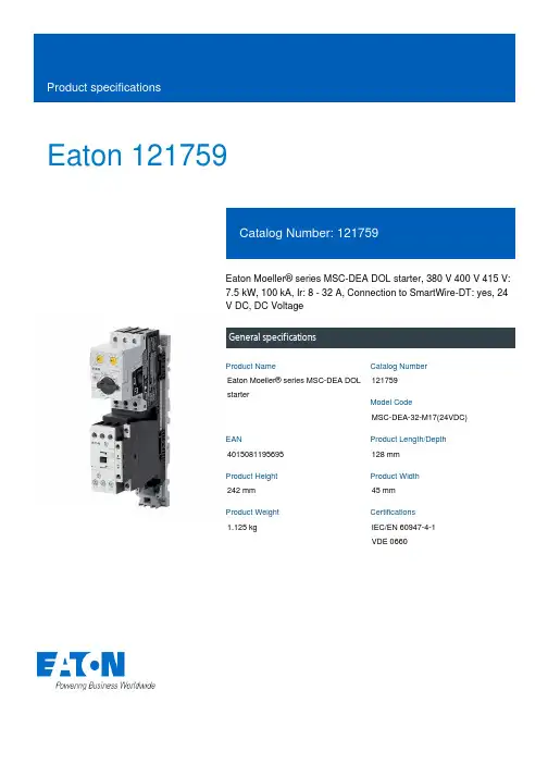
Eaton 121759Eaton Moeller® series MSC-DEA DOL starter, 380 V 400 V 415 V: 7.5 kW, 100 kA, Ir: 8 - 32 A, Connection to SmartWire-DT: yes, 24 V DC, DC VoltageGeneral specificationsEaton Moeller® series MSC-DEA DOL starter121759MSC-DEA-32-M17(24VDC)4015081195695128 mm 242 mm 45 mm 1.125 kgIEC/EN 60947-4-1 VDE 0660Product NameCatalog Number Model CodeEANProduct Length/Depth Product Height Product Width Product Weight Certifications17 AIs the panel builder's responsibility. The specifications for the switchgear must be observed.7.5 kW230 - 415 V AC0 A0 VMeets the product standard's requirements.Is the panel builder's responsibility. The specifications for the switchgear must be observed.DIN rail≤ 500 ms, main conducting paths, AC-4 cycle operationDoes not apply, since the entire switchgear needs to be evaluated.0 kW0 kWMeets the product standard's requirements.24 VShort-circuit release Simple, flexible and safe! Distribution system for motor-starter combinationsSave time and space thanks to the new link module PKZM0-XDM32ME Motor Starters in System xStart - brochureProduct Range Catalog Switching and protecting motorsDA-DC-00004245.pdfDA-DC-00004109.pdfeaton-manual-motor-starters-dol-starter-msc-d-dimensions.epseaton-manual-motor-starters-mounting-msc-d-dol-starter-3d-drawing.eps eaton-manual-motor-starters-dol-starter-msc-d-3d-drawing-002.eps eaton-general-ie-ready-dilm-contactor-standards.epsDA-CE-ETN.MSC-DEA-32-M17(24VDC)IL03402010ZWIN-WIN with push-in technologyDA-CS-msc_de_bg2DA-CD-msc_de_bg2eaton-manual-motor-starters-msc-d-dol-starter-wiring-diagram.epsRated operational current for specified heat dissipation (In) 10.11 Short-circuit ratingRated operational power at AC-3, 380/400 V, 50 Hz Rated operational voltageRated conditional short-circuit current, type 1, 480 Y/277 V Rated control supply voltage (Us) at AC, 50 Hz - min10.4 Clearances and creepage distances10.12 Electromagnetic compatibilityMounting methodCut-out periods - min10.2.5 LiftingRated power at 575 V, 60 Hz, 3-phaseRated power at 460 V, 60 Hz, 3-phase10.2.3.1 Verification of thermal stability of enclosures Rated control supply voltage (Us) at DC - minFitted with:BrochuresCatalogs Certification reports DrawingseCAD model Installation instructions Installation videos mCAD modelWiring diagramsCurrent flow times - min700 (Class 10) AC-4 cycle operation, Main conducting paths 1000 (Class 20) AC-4 cycle operation, Main conducting paths For all combinations with an SWD activation, you need not adhere to the minimum current flow times and minimum cut-out periods.500 (Class 5) AC-4 cycle operation, Main conducting paths900 (Class 15) AC-4 cycle operation, Main conducting paths Note: Going below the minimum current flow time can cause overheating of the load (motor).Number of pilot lightsRated control supply voltage (Us) at AC, 50 Hz - max0 VCoordination type210.8 Connections for external conductorsIs the panel builder's responsibility.Coordination class (IEC 60947-4-3)Class 2Rated conditional short-circuit current, type 1, 600 Y/347 V0 AAmbient operating temperature - max55 °CRated operational power at AC-3, 220/230 V, 50 Hz4 kWConnection to SmartWire-DTIn conjunction with PKE-SWD-32 SmartWire DT PKE module YesNumber of command positionsStatic heat dissipation, non-current-dependent Pvs0.86 WElectrical connection type of main circuitScrew connectionRated conditional short-circuit current (Iq), 500 V50 AElectrical connection type for auxiliary- and control-current circuit Screw connectionPower consumption (sealing) at DC0.86 WRated control supply voltage (Us) at DC - max24 V10.9.3 Impulse withstand voltageIs the panel builder's responsibility.Ambient operating temperature - min-25 °C10.6 Incorporation of switching devices and componentsDoes not apply, since the entire switchgear needs to be evaluated.10.5 Protection against electric shockDoes not apply, since the entire switchgear needs to be evaluated.ClassAdjustable10.13 Mechanical functionThe device meets the requirements, provided the information in the instruction leaflet (IL) is observed.10.2.6 Mechanical impactDoes not apply, since the entire switchgear needs to be evaluated.10.9.4 Testing of enclosures made of insulating materialIs the panel builder's responsibility.10.3 Degree of protection of assembliesDoes not apply, since the entire switchgear needs to be evaluated.Heat dissipation per pole, current-dependent Pvid2.7 WActuating voltage24 V DCVoltage typeDCOverload release current setting - min8 AEquipment heat dissipation, current-dependent Pvid8.2 WHeat dissipation capacity Pdiss0 WRated operational current (Ie)16.7 ASuitable forAlso motors with efficiency class IE3Number of auxiliary contacts (normally closed contacts)1Rated conditional short-circuit current (Iq), type 2, 380 V, 400 V, 415 V100000 A10.2.3.2 Verification of resistance of insulating materials to normal heatMeets the product standard's requirements.10.2.3.3 Resist. of insul. mat. to abnormal heat/fire by internal elect. effectsMeets the product standard's requirements.Rated operational power at AC-3, 500 V, 50 Hz7.5 kWProtocolOther bus systemsOverload release current setting - max32 A10.9.2 Power-frequency electric strengthIs the panel builder's responsibility.Overvoltage categoryIIIDegree of protectionIP20NEMA OtherPollution degree3Rated control supply voltage (Us) at AC, 60 Hz - min0 V10.7 Internal electrical circuits and connectionsIs the panel builder's responsibility.Rated impulse withstand voltage (Uimp)6000 V ACConnectionScrew terminals10.10 Temperature riseThe panel builder is responsible for the temperature rise calculation. Eaton will provide heat dissipation data for the devices.FunctionsTemperature compensated overload protectionRated operational current (Ie) at AC-3, 500 V12.1 ARated conditional short-circuit current (Iq), type 2, 230 V 100000 ATypeStarter with electronic trip unit10.2.2 Corrosion resistanceMeets the product standard's requirements.10.2.4 Resistance to ultra-violet (UV) radiationMeets the product standard's requirements.10.2.7 InscriptionsMeets the product standard's requirements.Short-circuit release (Irm) - max496 ARated control supply voltage (Us) at AC, 60 Hz - max0 VRated operational current (Ie) at AC-3, 380 V, 400 V, 415 V 17 AModelDirect starterNumber of auxiliary contacts (normally open contacts)Eaton Corporation plc Eaton House30 Pembroke Road Dublin 4, Ireland © 2023 Eaton. All Rights Reserved. Eaton is a registered trademark.All other trademarks areproperty of their respectiveowners./socialmedia。
Eaton and Hybrid Electric Vehicle Powertrains- Past, Present, and FutureEaton’s HEV Roots Go DeepEaton Corporation has been involved in the evolution of electric and hybrid vehicles for over 20 years. During the late 1970s and throughout the 1980s, Eaton was heavily engaged in electric vehicle research and development helping to pioneer important technological advances such as the migration from brush-type DC motors to brush-less induction motors. Early projects included the installation of complete electric traction drive systems into Ford and Chrysler passenger car and light truck applications. In the late 1980s, Eaton put its electric vehicle program on hold because of the gap in commercially viable battery technologies. This proved to be a wise decision, since most electric vehicle programs were dropped throughout the industry during the ‘90s and replaced with hybrid electric and fuel cell vehicle programs.During this time, as Eaton continued to monitor these developments, they became convinced that battery technology for hybrid electric applications was approaching commercial viability. At the same time, forward-thinking end users and truck OEM customers were becoming more receptive to the idea of hybrid electric vehicles (HEV).Eaton Forms HEV Business Unit- Sharpens FocusIn January 2000, Eaton launched itself into the HEV world with an internally funded R&D program aimed at building a Class 7 prototype hybrid truck. In March 2000, Eaton formed an HEV powertrain business unit within their Truck Electronic Systems Division, focusing human talent and resources toward the development of commercially viable hybrid powertrain systems. The successful demonstration of the Class 7 prototype in November 2000 paved the way for a second prototype, aimed at the urban P&D segment in the Class 4 range, to be built in 2001.In late 2000, Eaton began to seek key partnerships with strategic fleets such as FedEx. During this time Eaton learned of FedEx Express’ plans to issue a Request for Information that was aimed at a Class 4 hybrid electric delivery step-van. Within just a few months, Eaton submitted a competitive proposal in response to an industry-wide Request for a Proposal issued by FedEx Express.On February 26, 2002, FedEx Expressannounced that it had selected three finalists--including Eaton-- in its search for a prototypeversion of a hybrid electric Class 4 step-van.Eaton delivered its prototype to FedEx inSeptember 2002, and that fall, was selected asthe sole supplier of 18 HEV powertrainprototypes to be installed in FedEx vehicles fortesting in four major metropolitan areas. At apress event in Washington D.C. in May 2003,FedEx Express proclaimed its leadership in the adoption of hybrid power in its fleet of Class 4 delivery vehicles, in cooperation with its powertrain supplier Eaton Corporation and advocacy group Environmental Defense.U.S. Senator Orrin Hatch (R-Utah) congratulates FedEx Express, Environmental Defense andEaton for launching an advanced technology vehicle that is "a bellwether for the rest of the nation and the world."Adding importance to the event were appearances by U.S. Senator Orin Hatch (R-Utah) and Environmental Protection Agency director Christine Todd-Whitman, both hailing the announcement as a real and positive step towards the adoption of fuel-saving and pollution-reducing technologies.Meanwhile, in September 2002, Eaton was awarded a $7.1 million contract to lead a project in the Advanced Heavy Hybrid Propulsion System (AHHPS) Program sponsored by the U.S. Department of Energy. Through this program Eaton, in partnership with International Truck & Engine, will develop a heavy hybrid propulsion system designed to increase fuel efficiency and decrease emissions for commercial vehicles in the Class 4-7 weight range. Recently, a prototype UPS urban delivery vehicle was built using this new system and is currently in the testing stage.At the state capitol ceremony in SacramentoFedEx Express President David Bronczek explains the FedEx hybrid program to California Governor Arnold Schwarzenegger while Eaton’sJim Sweetnam and Fred Krupp of EnvironmentalDefense look on. On March 30, 2004, at a state capitol ceremonyin Sacramento, CA, FedEx Express, incollaboration with Sacramento Metropolitan AirQuality Management District and EnvironmentalDefense, placed the first of 18 Eaton hybridelectric powered delivery vehicles into service.The official rollout of the FedEx OptiFleet E700took place on the capitol steps with CaliforniaGovernor Arnold Schwarzenegger inattendance. Since late February, two FedExOptiFleet vehicles have been tested in theSacramento area to demonstrate thecommercial viability of the lower-emissionpowertrain in heavy-duty vehicles. Throughout the rest of 2004, Eaton will be placing an additional 16 trucks into service in selected cities. These trucks will endure real-world FedEx operating conditions to verify and provetheir viability in commercial applications.In May 2004, Eaton, in collaboration with International Truck and Engine, submitted a proposal to build a hybrid electric drive system for heavy-duty utility trucks. The proposal was submitted in response to a Request for Proposal from the HTUF Utility Hybrid Truck Working Group (Hybrid Task Force). Before submitting their proposal Eaton and International conducted several “Day-in-the-Life” sessions with members of the HTUF Utility Task Force Fleets. These sessions were held to better understand how the equipment is used in the field and have directly impacted the proposed design. In August 2004, the HTUF Working Group notified Eaton and International that their proposal had been selected.In October 2004, Eaton will host the fourth annual national meeting for the Hybrid Truck Users Forum (HTUF) in Kalamazoo, MI. In addition to hosting the event, Eaton will showcase several HEV commercial vehicle prototypes of varying vocations with a “ride-and-drive” at the Eaton Proving Grounds in Marshall, MI.Eaton’s Hybrid Mission & StrategyHybrid electric systems are critical to the automotive and truck industry’s technological roadmap that ultimately leads to fuel cell powertrains and beyond. The successful introduction of electric motor drives, inverters, energy storage devices and advanced power management controls on HEVs will pave the way for future migration to fuel cell powertrains.Eaton recognizes that in order to be commercially viable, hybrid electric vehicles will need to deliver significant fuel savings and environmental benefits. They are convinced that the most successful hybrid products will have the lowest price premiums compared to conventional vehicles as well as demonstrate exceptional reliability “out-of-the-box.” These objectives are what drives Eaton’s commitment to develop a hybrid electric system that will enable truck OEMs and engine manufacturers to comply with strict emissions regulations, reduce fuel consumption, improve drivability and increase functionality by providing on-board electrical power generation.By combining their successful automated manual transmission and clutch products with electric motor drives and related components, Eaton will be able to create integrated hybrid drivetrain units that are attractive to various commercial truck segments.Product Strategy: Series Vs. ParallelWhen building an HEV powertrain there are two basic configurations: series and parallel.• A “series” configuration has a generator mounted directly to the engine. All power from the engine is converted directly into electrical energy, which is then used to drive traction motors at the axle or wheel ends. In this type of design there is no mechanical drive path between the engine and the drive wheels.• A “parallel” configuration maintains conventional mechanical drivetrain architecture, but adds the ability to augment engine torque with electrical horsepower. A parallel system provides operating redundancy not found in a series system, whereby the conventional power can continue to operate in the event of an electrical power malfunction.Eaton is focused on developing parallel-hybrid drivetrainsystems that provide the best cost-benefit balance formany commercial truck applications. Most hybridsuppliers began working on series-hybrid systems andhave since transitioned to parallel hybrid architecture forsimilar reasons.Eaton’s first prototype truck featured a Full Hybridsystem that made it possible to operate the engineindependently from the vehicles’ road load conditions.This freedom was accomplished by combining a CVT-like device with an electric motor used to fill the gap between the most desirable engine operating conditions and the vehicle operating demands. The Full Hybrid An Eaton Fuller automated medium-duty transmission is fitted with an automated clutch and an electric motor-generator in the latest prototype.architecture provides the maximum potential for reducing fuel consumption and exhaust emissions of commercial trucks.Eaton’s second prototype truck features a Direct Hybrid system that incorporates an electric motor/generator located between the output of an automated clutch and the input to the AutoShift® transmission. This architecture makes it possible to recover energy normally lost during braking and store that energy in batteries or other devices. Electric torque can be blended with engine torque to improve vehicle performance and to operate the engine in the most fuel-efficient range for a given speed or to operate the vehicle with electric power only. In addition, this configuration creates a built-in power generator function into the vehicle for applications where remote power may be critical. Finally, this design provides a level of redundancy by enabling the vehicle to operate in electric-only or engine-only modes if the other system experiences a failure.Product and Technology DevelopmentHybrid electric vehicles require an unprecedented level of integration and partnership between truck OEMs, the engine manufacturer, and the suppliers of the drivetrain and major electrical components. Eaton’s strategy includes early and significant collaboration with truck OEMs, engine manufacturers and key technology/component suppliers.Eaton plans to offer complete, integrated Hybrid Drive Units to truck OEMs that include automated clutch, electric motor/generator, motor controller/inverter, energy storage, automated manual transmission, and an integrated supervisory Hybrid Control Module.Eaton’s HEV vision includes the Hybrid Drive Unit, which includes an automated clutch, a motor/generator,automated transmission and inverter/controls, as well as the supervisory Hybrid Control Module.HEV: Commercial StatusMany industry observers believe that hybrid electric technology is readily available. They point to the increasing popularity of passenger cars like the Toyota Prius and the Honda Insight as examples of successful passenger car applications. Recent moves by the transit departments in New York City and Seattle to purchase hundreds of hybrid electric transit buses are cited as examples of successful heavy hybrid vehicle application. Since most commercial trucks fall between the gross vehicle weights of these two hybrid examples, shouldn’t commercial trucks be an easy next step?Eaton, in partnership with International Truck & Engine, was recently selected by WestStart’s Hybrid Truck Users Forum (HTUF) to manufacture more than 20 advanced, pre-production hybrid-electric work trucks for national deployment and assessment.This is the first announcement by a U.S. truck OEM regarding production plans for Class 4-8 (light, medium and heavy-duty) hybrid vehicles. Unlike city buses and passenger cars, commercial trucks are subject to unique durability, reliability and operating requirements and expectations. For example, a typical passenger car’s useful life of 100,000 to 125,000 miles is not even close to being acceptable for commercial truck applications. Many commercial fleets put 100,000 miles or more on a truck in a single year. Other fleets may keep their trucks for 10 years or more.Today, the use of hybrid electric technology in commercial trucks faces many challenges. From a technological standpoint, these challenges include hybrid electric systems being able to create the increased torque and horsepower required in medium or heavy-duty trucks. The durability and reliability of battery systems and motor/inverter components must be proven in hybrid applications where battery cycles and operating environments are consistent with actual commercial truck field conditions before truck OEMs will invest in product development programs leading to production release. Furthermore, the production volumes of commercial trucks are much smaller than passenger cars, making it more difficult to recover the R&D and tooling investment. Thus, strong business cases from both the fleet operator and OEM manufacturer’s perspectives must be demonstrated before truck OEMs will commit to large investments. For these and other reasons, successful commercialization of hybrid electric trucks will require government support of initial technological development and demonstration of reliability in the field. In 2000, four federal government departments and 16 industrial partners, including Eaton, formed the 21st Century Truck Partnership to address these issues.The 21st Century Truck Partnership was formed to bring industry and the government together in research and development efforts and share the associated costs. The role of the federal agencies is to build on existing research and to assign priority to major new research identified by the Partnership. These research efforts will address concerns specific to all trucks, tractor-trailers, transit buses and military vehicles.Currently, Eaton is engaged in planning discussions with certain truck OEMs, engine manufacturers and key early adopter fleets. Increasingly, these discussions focus on characterizing sales volume forecasts and component cost structures required for successful commercialization.Eaton Hybrid In The NewsEaton’s rapid progress in hybrid power technology over the last two years has earned visibility not only in its own market, but by the general public as well. In addition to being featured in trucking industry news and environmental journals for its groundbreaking efforts, Eaton has also been featured along with its teammates FedEx Express and Environmental Defense on CNN and CNN Headline News, as well as CNBC, MSNBC, the New York Times and other national and international media.SummaryEaton has established a Hybrid Electric Powertrain business unit and is investing aggressively in the technology and product development necessary to develop commercially attractive solutions for cost effective, reliable hybrid drive systems. At present, Eaton is optimistic that battery durability, reliability and cost will improve to the point where these systems are attractive for commercial fleet customers. In the meantime, aggressive government R&D funding and purchasing incentives are essential to bridge the gaps between today’s technology and a significant hybrid penetration in the future.###。
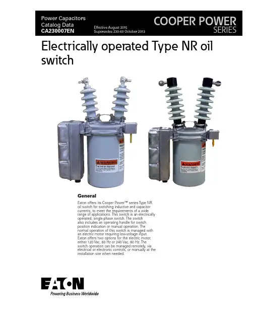
GeneralEaton offers its Cooper Power™ series Type NR oil switch for switching inductive and capacitor currents, to meet the requirements of a wide range of applications. This switch is an electrically operated, single-phase switch. The switch also includes an operating handle for switch position indication or manual operation. Thenormal operation of this switch is managed with an electric motor requiring low-voltage input. Eaton offers two options for the electric motor, either 120 Vac, 60 Hz or 240 Vac, 60 Hz. The switch operation can be managed remotely, via electrical or electronic controls, or manually at the installation site when needed.Electrically operated Type NR oilswitchFigure 1. Untanked T ype NR oil switch.DescriptionThe Type NR oil switch is a single-phase device for use ondistribution circuits. Compact design makes these switches ideal for use on capacitor banks, especially pole-top installations. These switches are electrically operated and can be controlled by various electrical or electronic devices. An operating handle, which also serves as a contact position indicator, is provided for manually opening and closing the switch.otee:N The Type NR oil switch may not be manually closed into a faulted line. The making current rating to these switches applies to electrical operation only.Capacitor bank switching The standard Type NR single-phase oil switch is rated at 15.0 kV / 95 kV BIL and is capable of switching three-phase capacitor banks up to 3600 kVAR on 14.4 kV systems; with three (3) switches controlledby customer. Choosing the 125 kV BIL option enables switchingsolidly grounded capacitor banks up to 6400 kVAR on multigrounded wye systems up to 14.4 / 24.9 kV; with three (3) switches controlled by customer.The 22.0 kV / 125 kV BIL version of the Type NR oil switch can switch solidly grounded three-phase capacitor banks up to 2700 kVAR on 20 / 34.5 kV multigrounded-wye systems; with three (3) switches controlled by customer. OperationWith switch contacts closed, selecting the "OPEN SWITCH", or similar, position in the switch controls energizes the switch opencontacts on the electric motor. Through a gear and lever system, this releases a toggle which allows pre-loaded opening springs to snap open the switch contacts; loads a heavy spring in preparation for aclosing operation; positions selector switch contacts so that only the closing circuit can subsequently be energized; and interrupts the electric motor operating current when the first three functions have been completed. The opening circuit must remain energized for 4.0seconds.Similarly, selecting the "CLOSE SWITCH", or similar, position in theswitch controls energizes the switch close contacts on the electric motor. This releases the closing spring to close switch contacts and load opening springs; positions selector switch contacts for the subsequent opening signal, then interrupts the operating electricmotor current. The closing circuit must remain energized for 0.5 seconds.BUSHING TERMINALSaluminum conductors, either vertically or horizontallyLIFTING STRAPconvenient for hoisting entire switch or for lifting mechanism from tankACTUATOR HOUSINGmotor-driven mechanism for electri-cally opening and closing the switchSTATIONARY CONTACTSand durable arcing tips, accessible for easy inspection or cleaningBUSHINGSwet-process porcelain with light-gray glaze. Munsell Gray 70SLEET HOODprotects manual operat-ing handle: switch data permanently affixed on nameplateO-RING GASKETin confined assembly provides weather-proof head-tank sealallows hookstick operation and serves as contact position indicator* General purpose duty switches are rated for both capacitive and inductive current switching applications.T able 1. Summary of RatingsSwitch TypeApplicationMaximumOperating Voltage (kV)Rated Switching Current (A)NR General Purpose Duty15.0200*NRV22.0602Catalog Data CA230007ENEffective August 2015Electrically operated T ype NR oil switch/cooperpowerseriesT able 2. Ratings and SpecificationsDescriptionStandard15 kV with 17" Creepage15 kV with 125 kV BIL22 kVMaximum Design Voltage, kV 15.015.015.022.0Nominal Operating Voltage, kV 2.4-14.4 2.4-14.4 2.4-14.420.0Basic Insulation Level (BIL), kV 959512512560 Hertz Withstand Voltage, kV Dry, One Minute Wet, Ten seconds3530353042366050Continuous Current Rating, Amps20020020060Load Interrupting Ability (Inductive), Symmetric Amps 75-100% power factor 50-75% power factor < 50% power factor20010050A 20010050A 20010050A 606060Maximum Capacitive Current, Amps (parallel bank-max)200200200*60* High Frequency Transient Current, Amps 12000120001200012000 Transient Frequency, Hz 6000600060006000 High Frequency Damping Factor .40-.55.40-.55.40-.55.40-.55Momentary Rating, Amps asym.9000900090009000Short Time Current Amps 1/2 second,sym. 1 second, sym.60004500600045006000450060004500Close and Latch Rating, Amps asym.9000900090009000T able 3. Electrical Data (Control)DescriptionRatingNominal operating voltage (50/60 Hz only) (Vac)120240Operating voltage range (Vac)95-130190-260Closing-motor current (A)1.9.7Switch response time, opening (sec) 4.0 4.0Switch response time, closing (sec)0.50.5*The 125 kV BIL switch and the 22.0 kV switch are rated for single bank switching only.3Catalog Data CA230007ENEffective August 2015Electrically operated T ype NR oil switch /cooperpowerseriesT able 4. Basic NR and NRV Oil SwitchesDescriptionNominal/Maximum Voltage (kV)Continuous Current (A)Switch BIL (kV)Type NR Oil Switch 14.4/15.020095*Type NRV Oil Switch20.060125* 125 kV BIL option available for standard NR oil switchOrdering informationWhen ordering the Type NR electrically operated oil switch specify the Voltage Rating from Table 4. The basic Type NR oil switch is designed with a maximum operating voltage of 15.0 kV L -L with a continuous current rating of 200 A. The Type NRV oil switch is designed with a maximum operating voltage of 22.0 kV with a continuous current rating of 60 A.T able 5. NR / NRV Motor Control VoltageDescription120 Vac Actuating Motor (Standard)240 Vac Actuating MotorControl voltage requirementsSpecify the Type NR motor control voltage from Table 5. The Type NR oil switch is supplied with a 120 Vac motor control voltage as standard.T able 6. NR / NRV Switch BIL & Bushing Creep*DescriptionRating (kV)BIL (kV)Bushing Creep (in)NR Oil Switch 15.09512.0NR Oil Switch 15.09517.0NR Oil Switch 15.012516.0NRV Oil Switch22.012517.0Insulation and creep requirementsSpecify the NR oil switch insulation level and porcelain insulator creep using Table 6. The NR oil switch is designed with 95 kV BIL insulation level as a standard option with a porcelain bushing having 12 inches of creep. The 95 kV BIL insulation level is only available in the NR oil switch. The NRV oil switch has an insulation level of 125 kV BIL and a porcelain bushing with 17.0" of creep as a standard offering.T able 7. NR / NRV T ank OptionsDescriptionSwitch Rating (kV)Standard Tank 15.022.0Stainless Steel Tank 15.022.0Zinc Plated Tank15.022.0Specialized tank requirementsSpecify the required NR tank option from Table 7. The standard tank is manufactured from a mild formed steel and painted toprotect against the environment. There are available options for zinc plating and stainless steel tanks for highly corrosive and salt-fog contaminated environments.T able 8. NR / NRV Low Voltage ArresterDescriptionNone (Std)120 Vac Surge Arrester (Factory Installed)Surge protection requirementsThere is an available option for a factory-installed 120 Vac low voltage surge arrester to protect the motor control circuit from damaging effects of lightning. The arrester rating is determined by the motor control voltage. Contact the factory if a 240 Vac low voltage arrester is required.T able 9. NR / NRV Auxiliary SwitchDescriptionNone (Std)Auxiliary SwitchAuxiliary switch requirementsSpecify the Auxiliary switch from Table 9 if necessary for theswitching application. The Auxiliary switch is a SPDT switch, which allows the user to remotely obtain the close or open position of the Type NR oil switch.*Reference Figure 4 on page 9 for outline dimensions of the extra creep bushing"* Determined by motor control voltage4Catalog Data CA230007ENEffective August 2015Electrically operated T ype NR oil switch/cooperpowerseriesT able 10. NR / NRV Hold SwitchDescriptionNone (Std)Hold SwitchHold switch requirementsSpecify the Hold switch from Table 10 if necessary for theapplication. The close or open signals supplied to the Type NR oil switch must be applied for a minimum of 4.5 seconds. Specify the Hold switch option from Table 10 if the capacitor switchingapplication requires a signal for less than 4.5 seconds. The close or open signal has to be applied for 1 second for proper operation of the Type NR oil switch.T able 11. Factory-wired ReceptaclesDescription5-pin/3-conductor receptacle for standard three-wire control 6-pin/6-conductor receptacle for auxiliary switchReceptacle assembly requirementsSpecify the type of receptacle from Table 11 for the switchingapplication. The receptacle assemblies are mounted in the bottom of the actuator housing and provide a convenient, weather-proof connection to switch the control circuits. Receptacles are supplied with 5-pin. 3-conductor or 6-pin, 6-conductor configurations. Reference Figure 2 for 5-pin or 6-pin receptacle orientations. Consult the factory for additional receptacle options.5-pin Receptacle6-pin ReceptacleFigure 2. Receptacle assembly schematic.* Consult factory for available receptacle options5Catalog Data CA230007ENEffective August 2015Electrically operated T ype NR oil switch /cooperpowerseriesT able 13. Wildlife Protectors for T erminal BushingsDescriptionCatalog NumberNone (Std)–Wildlife Protectors (95 kV BIL Only)*CCM32A1Wildlife Protectors (125 kV BIL only)*CCM33A1Wildlife protector requirementsSelect required wildlife protectors based on the Type NR switch being ordered for the application. Wildlife protectors protect the energized terminals of the Type NR switch from incidental contact from wildlife, tree branches or line crews performed routinemaintenance of overhead equipment. Wildlife protectors must be ordered in a quantity of 2.T able 14. Mounting OptionsDescriptionCatalog NumberNone (Std)–NEMA ® X-Arm BrktHA00039Mounting option requirementsSelect the Type NR oil switch mounting method from Table 14. The standard Type NR switch is supplied with an integral bracket, which is used for pole-mounting or capacitor rack applications. A NEMA ®-style bracket is available for cross-arm applications.T able 12. Mating Plug and Conductor Cable OptionsDescriptionCatalog Number5-Pin Mating PlugCCR010P15-Pin / 3-Conductor Cable (6 ft)CCR003P65-Pin / 3-Conductor Cable (8 ft) CCR003P85-Pin / 3-Conductor Cable (10 ft) CCR003P105-Pin / 3-Conductor Cable (12 ft) CCR003P125-Pin / 3-Conductor Cable (14 ft) CCR003P145-Pin / 3-Conductor Cable (16 ft) CCR003P165-Pin / 3-Conductor Cable (18 ft) CCR003P185-Pin / 3-Conductor Cable (20 ft) CCR003P205-Pin / 3-Conductor Cable (22 ft) CCR003P225-Pin / 3-Conductor Cable (24 ft) CCR003P245-Pin / 3-Conductor Cable (26 ft) CCR003P265-Pin / 3-Conductor Cable (28 ft) CCR003P285-Pin / 3-Conductor Cable (36 ft) CCR003P366-Pin Mating PlugCCR009P16-Pin / 6-Conductor Cable (6 ft) CCR006P66-Pin / 6-Conductor Cable (8 ft) CCR006P86-Pin / 6-Conductor Cable (10 ft) CCR006P106-Pin / 6-Conductor Cable (12 ft) CCR006P126-Pin / 6-Conductor Cable (14 ft) CCR006P146-Pin / 6-Conductor Cable (16 ft) CCR006P166-Pin / 6-Conductor Cable (18 ft) CCR006P186-Pin / 6-Conductor Cable (20 ft) CCR006P206-Pin / 6-Conductor Cable (22 ft) CCR006P226-Pin / 6-Conductor Cable (24 ft) CCR006P246-Pin / 6-Conductor Cable (26 ft) CCR006P266-Pin / 6-Conductor Cable (28 ft)CCR006P286-Pin / 6-Conductor Cable (36 ft)CCR006P36Mating plug & conductor cable requirementsSpecify the type of mating plug and conductor cable configuration and length from Table 12 if required for the switching application.5-pin plugs accommodate up to 12 AWG wire and 0.375-0.500 inch O.D cables to allow connection to the 5-pin receptacle.6-pin plugs accommodate up to 16 AWG wire and 0.500-0.625 inch O.D cables to allow connection to 6-pin receptacles. The number of conductors tabulated for the receptacles in Table 12 above indicates the number of pins wired to the actuator terminal strip. Mating plugs are available as an accessory and should be ordered separately. Consult the factory for additional mating plug and conductor cable options.* Consult factory for additional Conductor C able options* Must be ordered in a quantity of (2)6Catalog Data CA230007ENEffective August 2015Electrically operated T ype NR oil switch/cooperpowerseriesStandard Type NR Oil Switch Catalog Number ConfigurationThe standard Type NR and NRV configurations are provided below. If you need Engineered To Order (ETO) models, please contact your Eaton representative for details.Table 4-S witch TypeNR (15 kV)Type NR (15.0 kV) CCM17B2-GType NRV (22.0 kV)CCM75B2-GTable 5-Control Motor120 Vac (Std)Table 6-BIL & Creep*95 kV BIL (15.0 kV Only)Table 7-Tank OptionsStandard TankTable 8-L V Surge ArresterNone (Std)Table 9-Auxiliary SwitchNone (Std)Table 10-Hold SwitchNone (Std)Table 11-Receptacle5 -Pin / 3-Conductor (Std)Table 12-Plug & CableNone (Std)Table 13-Bird GuardsW/O Bird Guards (Std)Table 14-Mounting OptionsNone (Std)Table 4-S witch TypeNRV (22.0 kV)Table 5-Control Motor120 Vac (Std)Table 6-BIL & Creep*125 kV BILTable 7-Tank OptionsStandard TankTable 8-L V Surge ArresterNone (Std)Table 9-Auxiliary SwitchNone (Std)Table 10-Hold SwitchNone (Std)Table 11-Receptacle5 Pin / 3-Conductor (Std)Table 12-Plug & CableNone (Std)Table 13-Bird GuardsW/O Bird Guards (Std)Table 14-Mounting OptionsNone (Std)*Reference Figure 3 on page 8 for NR oil switch outline dimensions*Reference Figure 5 on page 10 for NRV outline dimensions7Catalog Data CA230007ENEffective August 2015Electrically operated T ype NR oil switch /cooperpowerseriesFOR FACTORY-WIRED RECEPTACLEFigure 3. Outline dimensions of 95 kV BIL T ype NR oil switch with standard bushings, (15.0 kV Rating ONL Y).8Catalog Data CA230007ENEffective August 2015Electrically operated T ype NR oil switch/cooperpowerseriesFigure 4. Outline dimensions of 95 kV BIL T ype NR oil switch with 17" creepage bushings, (15.0 kV Rating ONL Y).9Catalog Data CA230007ENEffective August 2015Electrically operated T ype NR oil switch /cooperpowerseriesFOR FACTORY-WIRED RECEPTACLEFigure 5. Outline dimensions of 125 kV BIL T ype NR oil switch (15.0 and 22.0 kV).10Catalog Data CA230007ENEffective August 2015Electrically operated T ype NR oil switch/cooperpowerseriesCatalog Data CA230007EN Electrically operated T ype NR oil switchEffective August 201511/cooperpowerseriesElectrically operated T ype NR oil switch Eaton 1000 Eaton Boulevard Cleveland, OH 44122United States Eaton’s Cooper Power Systems Division 2300 Badger Drive Waukesha, WI 53188United States /cooperpowerseries© 2015 Eaton All Rights Reserved Printed in USA Publication No. CA230007EN Catalog Data CA230007EN Effective August 2015Eaton is a registered trademark.All other trademarks are property of their respective owners.For Eaton's Cooper Power series Type NR oil switch product information call 1-877-277-4636 or visit: /cooperpowerseries.。
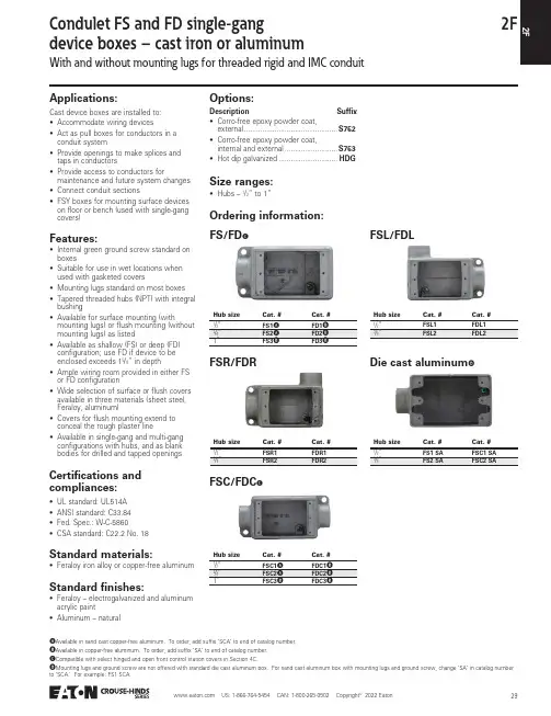
2FApplications:Cast device boxes are installed to:• Accommodate wiring devices• Act as pull boxes for conductors in a conduit system• Provide openings to make splices and taps in conductors• Provide access to conductors formaintenance and future system changes • Connect conduit sections• FSY boxes for mounting surface devices on floor or bench (used with single-gang covers)Features:• Internal green ground screw standard on boxes• Suitable for use in wet locations when used with gasketed covers• Mounting lugs standard on most boxes • Tapered threaded hubs (NPT) with integral bushing• Available for surface mounting (withmounting lugs) or flush mounting (without mounting lugs) as listed• Available as shallow (FS) or deep (FD) configuration; use FD if device to be enclosed exceeds 15/8” in depth• Ample wiring room provided in either FS or FD configuration• Wide selection of surface or flush covers available in three materials (sheet steel, Feraloy, aluminum)• Covers for flush mounting extend to conceal the rough plaster line• Available in single-gang and multi-gang configurations with hubs, and as blank bodies for drilled and tapped openingsStandard materials:• Feraloy iron alloy or copper-free aluminumStandard finishes:• Feraloy – electrogalvanized and aluminum acrylic paint• Aluminum – naturalSize ranges:• Hubs – 1/2” to 1”Certifications and compliances:• UL standard: UL514A • ANSI standard: C33.84• Fed. Spec.: W-C-5860• CSA standard: C22.2 No. 18FS/FDCDie cast aluminumDWith and without mounting lugs for threaded rigid and IMC conduitCondulet FS and FD single-gangdevice boxes – cast iron or aluminumOptions:Description Suffix • Corro-free epoxy powder coat,external ..............................................S752• Corro-free epoxy powder coat,internal and external ..........................S753• Hot dip galvanized .............................HDGOrdering information:Hub sizeCat. #Cat. #1/“A B 1”FS3BFD3BA Available in sand cast copper-free aluminum. To order, add suffix ‘SCA’ to end of catalog number.B Available in copper-free aluminum. To order, add suffix ‘SA’ to end of catalog number.C Compatible with select hinged and open front control station covers in Section 4C.D Mounting lugs and ground screw are not offered with standard die cast aluminum box. For sand cast aluminum box with mounting lugs and ground screw, change ‘SA’ in catalog numberto ‘SCA.’ For example: FS1 SCA.FSR/FDR Hub sizeCat. #Cat. #1/“FSR1FDR1FSC/FDC CHub sizeCat. #Cat. #1/“AB 1”FSC3BFDC3BFSL/FDLHub sizeCat. #Cat. #1/“FSL1FDL1Hub sizeCat. #Cat. #1/“FS1 SA FSC1 SA22FDimensions (in inches):FSA/FDAEFOrdering information (continued):Hub size Cat. #Cat. #1/“FSA1FDA1E Mounting lugs not available.F Back entry hub is threaded.G Available in copper-free aluminum. To order, add suffix ‘SA’ to end of catalog number.FSS/FDD EHub size Cat. #Cat. #1/“G FDD11”FSCC/FDCCHub size Cat. #Cat. #1/“FSCC1FDCC1FSCA FHub size Cat. #1/“FSCA1FSSAEFHub size Cat. #3/4“FSSA2FSLA/FDLAFHub size Cat. #Cat. #1/“FSLA1FDLA1Series Hub size a b c d1/“7/17/111/5/ With and without mounting lugs for threaded rigid and IMC conduitCondulet FS and FD single-gangdevice boxes – cast iron or aluminum2FHub sizeCat. #1/“FSCD1Ordering information (continued):FSCT/FDCTFDXCIJDimensions (in inches):FSCT, FSX, FST, FSCDFDXCFSYFSYIFSCT, FSX, FST, FSCDFSYHub size Cat. #Cat. #1/“FSCT1FDCT11”FSCT3FDCT3H Available in copper-free aluminum. To order, add suffix‘SA’ to end of catalog number.I Not available with mounting lugs.J Six hubs – all /” pipe tap.FST/FDTHub size Cat. #Cat. #1/“FST1FDT11”FDT3FSX/FDXHub size Cat. #Cat. #1/“FSX1FDX11”FDX3FSCD IDescriptionHub sizeCat. #Single face 1”FSY311Hub sizeCat. #3/4“FDXC219SeriesHub size a b c dFS1/“7/17/111/5/1”11/81/16/8DescriptionHub sizeabSingle-gang, single face 1”23/115/With and without mounting lugs for threaded rigid and IMC conduitCondulet FS and FD single-gangdevice boxes – cast iron or aluminum22FWith and without mounting lugsCondulet FS single-gangdevice boxes – cast iron or aluminumFS double faceKDimensions (in inches):Double faceOrdering information (continued):Hub sizeCat. #1/“FS152K Mounting lugs not available.FSC double face KHub sizeCat. #1/“FSC152SeriesHub sizea b c1/“35/31/11/2FCondulet FS and FD multi-gangdevice boxes – cast iron or aluminumWith and without mounting lugs for threaded rigid and IMC conduitFS two-gang tandemAFSC two-gang tandemAFS/FD two-gangFSC/FDC two-gangFSE two-gangDimensions (in inches):Two-gang tandem Two-gangTwo-gang tandemTwo-gangOrdering information:A Use single-gang covers only.B Available in copper-free aluminum. To order, add suffix ‘SA’ to end of catalog number.Hub sizeCat. #1/“FS17Hub size Cat. #Cat. #1/“B FD121”FS32FD32Hub sizeCat. #Cat. #1/“FSC12FDC121”FSC32FDC32Hub sizeCat. #1/“FSC17Hub sizeCat. #3/4“FSE22SeriesHub sizeade1/“7/5/11/SeriesHub sizeabcdh1/“7/21/17/111/5/22FOrdering information (continued):FSS/FDS two-gangFS/FD three-gangFSD two-gangFSS three-gangDimensions (in inches):Two-gang with mounting lugs Three-gangThree-gangHub sizeCat. #Cat. #3/4“FSS222FDS222Hub size Cat. #Cat. #3/“FS23FD23Hub sizeCat. #3/4“FSD212CC Hubs on two hub side are /”.Hub sizeCat. #3/4“FSS23SeriesHub sizeacd3/“7/17/111/FD/4“/82/162/2Condulet FS and FD multi-gangdevice boxes – cast iron or aluminumWith and without mounting lugs for threaded rigid and IMC conduit2FCondulet FS and FDblank device boxes – cast ironBlank bodies with mounting lugs for drilling and tapping Single-gang, multi-gang, tandemApplications:Blank cast device boxes are used:• Where several wiring devices are to be grouped together• To assemble special combinations of wiring devices• Where special arrangements of conduit hubs or entrances are requiredFeatures:• Available in shallow (FS) or deep (FD) configurations• FS/FD bodies have thick walls for drilling and tapping conduit entrances• Internal green ground screw standard on boxes• Available in single-, two-, three-, four- and five-gang, and two-gang tandem bodies • Cast mounting lugs at diagonally opposite cornersStandard material:• Feraloy iron alloyStandard finish:• Feraloy – electrogalvanized and aluminum acrylic paintCertifications and compliances:• UL standard: UL514A• CSA standard: C22.2 No. 18FS019, FD019 – single-gangFS029, FD029 – two-gangFS039, FD039 – three-gangFD04 – four-gangFD05 – five-gangFS062, FD062 – two-gangFS063, FD063 – three-gangFS094, FD094 – four-gangFS097, FD097 – two-gang tandemOrdering information:DescriptionCat. # Shallow Cat. # Deep Single-gang FS019FD019Two-gang tandemFS097FD097A Available in copper-free aluminum. To order, add suffix ‘SA’ to end of catalog number.22F Condulet FS and FD blankdevice boxes – cast ironBlank bodies for drilling and tappingSingle-gang, multi-gang, tandemOrdering information:To order one of the blank bodies with drilledand tapped holes listed on previous page,proceed as follows:Step 1Select the required box.Step 2Select the arrangement that meets therequirements from Table 1.Step 3Determine the maximum size and spacing ofconduit openings from Table 2.Step 4Substitute the appropriate symbol fromTable 4 for each conduit entrance, using “0”(zero) for those locations on arrangementwhere an entrance is not required.Example:Step 1 – box required FS062Step 2 – arrangement 1Step 3 – conduit entrances – 1/2” at ‘a’; noneat ‘b’; 1” at ‘c’ and ‘d’; none at ‘e’ and ‘f.’Step 4 – symbols are substituted and writtenin alphabetical order starting with location‘a.’ For this example: A0CC00.Complete catalog number is made up ofthree parts:Part 1 – box number;Part 2 – arrangement number;Part 3 – symbols for conduit entrances.For this example: FS062-1-A0CC00.Table 1 – Drilling and tapping arrangements: BTwo-, three-, four- and five-gangSingle-gang only (FS or FD019)Two-gang tandem (FS or FD097)12C3C4C5B Drilling and tapping arrangements other than those in Table 1 are available. Consult Eaton’s Crouse-Hinds Division.C If only one conduit entry is specified or permitted (see Table 2) on a side wall, that conduit entry will be centered on the wall.2FCondulet FS and FD cast device boxesBlank bodies for drilling and tappingSingle-gang, multi-gang, tandemTable 3 – Distance from mounting surface to center line of conduit opening (‘u’):Table 4 – Symbols for openings:Table 2 – Maximum number, size and spacing of conduit openings:Maximum conduit opening size Top and bottomSides Back Spacings Cat. #12345122svwxyzFS01911Cat. #uFS01929/Hub sizeSymbol1/”A22F Condulet FS and FDcast device boxesBlank bodies for drilling and tappingSingle-gang, multi-gang, tandemDimensions (in inches):FS/FD062FS/FD094FS/FD063FS/FD097Cat. #a bFS/FD01931/31/FD0518/818/4Cat. #a b c d e fFS06227/53/523/11/43/Cat. #a bFS09423/145/Cat. #a b c d e fFS063313/75/67/23/11/61/Cat. #a bFS09721/11/47 US: 1-866-764-5454 CAN: 1-800-265-0502 Copyright 2019 Commercial Products CatalogCast device boxesCast device boxesApplications:Cast device boxes are installed to:• Accommodate wiring devices• Act as pull boxes for conductors in a conduit system • Provide openings to make splices and taps in conductors • Use indoors and outdoors• Use in applications where boxes may be subjected to rough useFeatures:• Green ground screw is located on the flange of the box for easy ground wire termination and is standard on boxes• Suitable for use in wet locations when used with gasket and flat blank covers• Mounting lugs standard• Tapered threaded hubs (NPT) with integral bushing • Available as shallow (FS) or deep (FD) configuration• Ample wiring room provided in either FS or FD configuration • Wide selection of surface or flush covers available in three materials (sheet malleable, steel, aluminum)• Malleable iron construction provides high tensile strength for strong, dependable service• Covers are individually bagged and supplied with screwsStandard material:• Malleable ironStandard finish:• Malleable iron – zinc electroplateFS BOXESFSM1FSC BOXES FSCM1FD BOXESFDM1FDC BOXESFDCM1FS & FD boxesCat. #SizeUnit qty.Wt. lbs. per 100FSM11/”5222FSM31”5243Cat. #SizeUnit qty.Wt. lbs. per 100FDM11/”2278FDM31”2284Cat. #SizeUnit qty.Wt. lbs. per 100FSCM11/”5234FSCM31”5250Cat. #SizeUnit qty.Wt. lbs. per 100FDCM11/”2313FDCM31”2306Certifications and compliances:• c UL us • cCSAusOptions:Suffix • Hot dip galvanized ......................................................................HDGDescriptionCast device boxesFS & FD COVERS – MALLEABLEFBCM1SWCM1RCM1FS & FD COVERS – STEELFBCS1SWCS1RCS1GFICS1FS & FD COVERS – ALUMINUMFBCA1FS & FD BOX GASKETSFSGSK1FS & FD coversCat. #DescriptionUnitqty.Wt. lbs.per 100FBCM1Malleable iron flat blank cover2556RCM1Malleable iron duplex receptacle cover2555Cat. #DescriptionUnitqty.Wt. lbs.per 100FBCS1Steel flat blank cover2518Cat. #DescriptionUnitqty.Wt. lbs.per 100FBCA1Aluminum flat blank cover259Cat. #DescriptionUnitqty.Wt. lbs.per 100FSGSK1Neoprene gasket25 3.5 US: 1-866-764-5454 CAN: 1-800-265-0502 Copyright 2019 Commercial Products Catalog US: 1-866-764-5454 CAN: 1-800-265-0502 Copyright 2022 Eaton432FSingle-gang covers forcast iron or aluminum device boxesBlank cover for enclosing splices and tapswhere device not usedBlank cover with gasket for enclosingsplices and taps where device not usedDS21DS21GFor standard and 3-pole, 2-wiregrounding type round flush receptacles;opening diameter 17/16”For GFI receptaclesFor flush plug receptacle requiring 15/8”opening diameterFor duplex convenience receptaclesFor square handle general use snap ortoggle switches; unguardedAdapter plate for mounting WLRS/WLRDcovers to flush device boxesFor square handle general use snap ortoggle switches; guardedOrdering information:DescriptionMaterialCat. #Surface Sheet aluminum DS100DescriptionMaterialCat. #Surface or flushCast aluminumDS100GDescriptionMaterialCat. #Surface Sheet steel DS21Surface or flushalloy with gasketDS21GDescriptionMaterialCat. #Surface Sheet steelDS23 GFIDescriptionMaterialCat. #Surface Sheet steelDS35DescriptionMaterialCat. #Surface Sheet steel DS23Flush Sheet steelDSS23For standard and 3-pole, 2-wire grounding type duplex conveniencereceptacles; gasket includedDescriptionMaterialCat. #Surface or flush Feraloy iron alloyDS23GDescriptionMaterialCat. #Surface Sheet steel DS32DescriptionMaterialCat. #Surface or flush Feraloy iron alloy with DS32G DescriptionCat. #Flush device adapterWLRA1Note: A lso can be used to mount all covers with fourcorner screws listed to flush device boxes. US: 1-866-764-5454 CAN: 1-800-265-0502 Copyright 2022 Eaton4422FRaintight covers A (gasket included)ARaintight cover includes operator lever only. Switch not included.For general use snap switches; includesgasketFor general use snap switches; includesgasketFor general use snap switches; includesgasketOrdering information:Single-gang covers forcast iron or aluminum device boxesDescriptionMaterialCat. #For standard ON-OFF operationCopper-free aluminumDS181DescriptionMaterialCat. #For standard ON-OFFoperation; with hole for lockDie cast aluminumDS185DescriptionMaterialCat. #For standardoperation; marked ON-OFF handleCast aluminumDS128Raintight US: 1-866-764-5454 CAN: 1-800-265-0502 Copyright 2022 Eaton452FSwitch and motor control pushbutton covers AA Covers include operating lever or button only. Switch not included.BTwo universal contact blocks; must be wired as two circuits, with one normally open and one normally closed.Furnished with buttons for operating motor control pushbutton switches;includes gasket① If desired, markings on indicating plates may be added to catalog number. Select from the list of standard markingsbelow:For manual motor starting switches; fits FS and FD boxes; takes Westinghouse switches MST01 (1-pole) and MST02(2-pole); includes gasketHeavy duty motor control pushbutton switchDS covers use the switches shown in the list below:Ordering information:DescriptionMaterialCat. #For standard ON-OFF operationFeraloy iron alloyDS199PushbuttonsDescriptionNo.ColorMaterialCat. #Button (normally open) marked START 1Green Feraloy iron alloy ①button (normally closed) marked STOP1RedFeraloy iron alloyDS171 ①DescriptionNo.ColorMaterialCat. #Two pushbutton2Black Feraloy iron alloyDS171J ①HAND CLOSE OFF AUTO.UP RUNNo. of buttonsNormal positionsCat. #1 1 circuit universal ED11CoverTakes switchCoverTakes switchDS171ED12DS171F ED11DS265ED11Single-gang covers forcast iron or aluminum device boxesRaintight US: 1-866-764-5454 CAN: 1-800-265-0502 Copyright 2023 Eaton4522FDS receptacles and WP plugsWeatherproofApplications:DS receptacles and WP plugs are used:• Wherever dust, dirt, moisture and corrosion are a problem• Outdoors or in locations where frequent wash downs occur, as in dairies and food processing plantsFeatures:DS receptacle housings are used:• With FS and FD cast device boxes, either surface mounted or installed flush in a wall• With single-gang, two-gang tandem and multi-gang boxes having individual cover openings• A threaded cap which effectively seals housing when not in use WP plugs include:• A molded neoprene hood with integral sleeve to seal the cord entrance• An aluminum ring which clamps the hood to receptacle housing face, to complete watertight seal when plug is in useStandard materials:• Receptacle housings – body: Feraloy iron alloy; cap: copper-free aluminum• Plug exteriors – hood: neoprene; fastening ring: copper-free aluminumStandard finishes:• Feraloy iron alloy – electrogalvanized and aluminum acrylic paint• Copper-free aluminum – natural • Neoprene – natural (black or yellow)Electrical ratings:• 20 amperes, 125 voltsCertifications and compliances:• UL standards: UL498; UL514A • NEMA/EEMAC: WD-1; WD-5• CSA standard: C22.2 No. 42DS receptacle housingsWP plugsCC replacement receptacleGrounding type receptaclesFor plugs with U shaped or round grounding contactsRatingCat. #Cover with recept.NEMAconfigurationStyleCat. # Plug NEMAconfigurationCord dia.Cat. # Repl. recept.20A,125VDS2225-20R2-wire,3-poleWP8325-20P0.500 - 0.625”CC71Single-gang covers forcast iron or aluminum device boxesOrdering information: US: 1-866-764-5454 CAN: 1-800-265-0502 Copyright 2022 Eaton472FPilot light covers, extensions and adaptersSingle-gang covers forcast iron or aluminum device boxesFor pilot light units(furnished with jewels)For pilot light units(furnished with jewel and gasket)Pilot light unit (without transformer)Pilot light (with transformer)A ;FD onlyEXF extensions(takes covers and flush rectangular wiring devices, or plug receptacles withhousings)FS flush mounting adapter(can be used with multi-gang bodies having individual cover openings);furnished with gasket and screwsGasket for use between device boxesand coversOrdering information:DescriptionMaterialJewel color Cat. #Surface Sheet steel Red DS24DescriptionMaterialJewel colorCat. #Surface or flush Feraloy iron alloyRedDS24GCircuit voltageLamp baseWattsCat. #110Candelabra 6C3310A Transformer 50-60 cycle, 440/110 volts.B Not recommended as watertight.Circuit voltageLamp baseWattsCat. #440Candelabra 6C333Ext. depthCat. #1”EXF11Mounting styleCat. #WallFS031MaterialCat. #NeopreneGASK91B4822F Two-gang covers forcast iron or aluminum device boxesFor flush general use snapswitches with square handles;hole diameter 111/32”For flush general use snap switches withsquare handles; hole diameter 113/32”For standard and 2-wire, 3-polegrounding; hole diameter 113/32”For duplex convenience receptacles,standard and 2-wire, 3-pole grounding;hole diameter 111/32”For GFI receptacles; rectangular height25/8”; rectangular width 15/16”For round flush receptacles (holediameter 113/32”); duplex conveniencereceptacles, standard and 2-wire, 3-polegrounding (hole diameter 111/32”)Blank; Feraloy iron alloy with gasketFor flush general use snap switches withsquare handlesFor flush general use snap switches withsquare handles Ordering information:Material Cat. #Sheet steel S32232Description Material Cat. #For round plugflush receptacles;surfaceSheet steel S32212Description Material Cat. #For round plugflush receptacles;surfaceSheet steel S212Description Material Cat. #Surface Sheet steel S232Description Material Cat. #Surface Sheet steel S232 GFIDescription Material Cat. #Surface Sheet steel S21232For 20A, 250V receptacles;hole diameter 25/32”Description Material Cat. #2-pole, surface Sheet steel S612Description Material Cat. #Surface Sheet steel S1002flush aluminum S1002G SADescription Material Cat. #Surface Sheet steel S322Description Material Cat. #Surface or FeraloyS322G US: 1-866-764-5454 CAN: 1-800-265-0502 Copyright US: 1-866-764-5454 CAN: 1-800-265-0502 Copyright 2022 Eaton492FMulti-gang covers forcast iron or aluminum device boxesWith operating mechanism and gasketWith operating mechanism and gasketBlank with gasket includedFor flush general use snap switches withsquare handlesFor flush general use snap switches withsquare handlesBlank with gasket includedGasket for use between device boxand coverOrdering information:Two-gangThree-gangFour-gangDescriptionMaterialCat. #Two-gang; for operation of general use snap switches; surface or flushFeraloy iron alloyDS1282DescriptionMaterialCat. #Three-gang with gasket; forexternal operation of general use snap switches;surface or flushFeraloy iron alloyDS1283DescriptionMaterialCat. #Surface Sheet steel S1003flush aluminumS1003G SADescriptionMaterialCat. #Three-gang; surface Sheet steelS323DescriptionMaterialCat. #Surface or flush Feraloy iron alloyS1004GDescriptionMaterialCat. #Four-gang; surface Sheet steelS324GasketsDescriptionMaterialCat. #Two-gang Rubber GASK434Four-gangRubberGASK461。
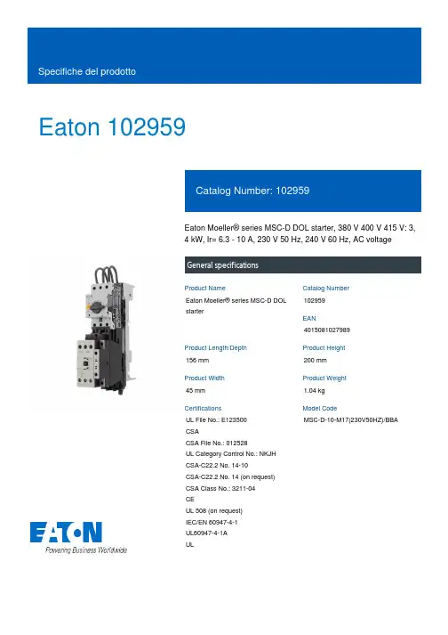
Eaton 102959Eaton Moeller® series MSC-D DOL starter, 380 V 400 V 415 V: 3,4 kW, Ir= 6.3 - 10 A, 230 V 50 Hz, 240 V 60 Hz, AC voltageGeneral specificationsEaton Moeller® series MSC-D DOLstarter1029594015081027989156 mm200 mm45 mm 1.04 kgUL File No.: E123500CSACSA File No.: 012528UL Category Control No.: NKJH CSA-C22.2 No. 14-10CSA-C22.2 No. 14 (on request) CSA Class No.: 3211-04CEUL 508 (on request)IEC/EN 60947-4-1UL60947-4-1AUL MSC-D-10-M17(230V50HZ)/BBAProduct Name Catalog NumberEANProduct Length/Depth Product Height Product Width Product Weight Certifications Model CodeShort-circuit releaseTemperature compensated overload protection CLASS 10 AScrew terminalsNo2IP00NEMA OtherDirect starterMounting on Busbar 60 mm6.3 A10 AIII36000 V ACAlso motors with efficiency class IE3 Starter with Bi-Metal releaseACFitted with: Functions ClassConnectionConnection to SmartWire-DTCoordination typeDegree of protectionModelMounting methodNumber of auxiliary contacts (normally closed contacts) Overload release current setting - minOverload release current setting - maxOvervoltage categoryPollution degreeRated impulse withstand voltage (Uimp)Suitable forTypeVoltage typeMax. 2000 m -25 °C55 °C 8.5 A10 A2.2 kW4 kW230 - 415 V AC15 A, 600 V AC, (UL/CSA)1 A, 250 V DC, (UL/CSA)P300, DC operated (UL/CSA) A600, AC operated (UL/CSA)50000 A 155 A 2.1 W, Dual-frequency coil in a cold state and 1.0 x Us, at 50 Hz 230 V230 V0 V0 V0 V0 VAltitudeAmbient operating temperature - min Ambient operating temperature - max Rated operational current (Ie)Rated operational current (Ie) at AC-3, 380 V, 400 V, 415 V Rated operational power at AC-3, 220/230 V, 50 HzRated operational power at AC-3, 380/400 V, 50 HzRated operational voltageSwitching capacity (auxiliary contacts, general use) Switching capacity (auxiliary contacts, pilot duty)Rated conditional short-circuit current (Iq), type 2, 380 V, 400 V, 415 VShort-circuit release (Irm) - max Power consumption, sealing, 50 HzRated control supply voltage (Us) at AC, 50 Hz - min Rated control supply voltage (Us) at AC, 50 Hz - max Rated control supply voltage (Us) at AC, 60 Hz - min Rated control supply voltage (Us) at AC, 60 Hz - max Rated control supply voltage (Us) at DC - minRated control supply voltage (Us) at DC - max8.1 W0 W2.7 W10 A2.1 WMeets the product standard's requirements.Meets the product standard's requirements.Meets the product standard's requirements.Meets the product standard's requirements.Meets the product standard's requirements.Does not apply, since the entire switchgear needs to be evaluated.Does not apply, since the entire switchgear needs to be evaluated.Meets the product standard's requirements.Does not apply, since the entire switchgear needs to be evaluated.Meets the product standard's requirements.Does not apply, since the entire switchgear needs to be evaluated.Simple, flexible and safe! Distribution system for motor-starter combinationseaton-manual-motor-starters-adapter-msc-d-dol-starter-dimensions-002.epseaton-manual-motor-starters-adapter-msc-d-dol-starter-3d-drawing.epsDA-CE-ETN.MSC-D-10-M17(230V50HZ)_BBAIL03402015ZIL03402010ZDA-CD-msc_d_bba_bg2DA-CS-msc_d_bba_bg2DA-DC-00004106.pdfDA-DC-00004242.pdfeaton-manual-motor-starters-device-msc-d-dol-starter-wiring-diagram.epsEquipment heat dissipation, current-dependent PvidHeat dissipation capacity PdissHeat dissipation per pole, current-dependent PvidRated operational current for specified heat dissipation (In) Static heat dissipation, non-current-dependent Pvs10.2.2 Corrosion resistance10.2.3.1 Verification of thermal stability of enclosures10.2.3.2 Verification of resistance of insulating materials to normal heat10.2.3.3 Resist. of insul. mat. to abnormal heat/fire by internal elect. effects10.2.4 Resistance to ultra-violet (UV) radiation10.2.5 Lifting10.2.6 Mechanical impact10.2.7 Inscriptions10.3 Degree of protection of assemblies10.4 Clearances and creepage distances10.5 Protection against electric shock10.6 Incorporation of switching devices and components BrochureDisegnieCAD modelIstruzioni di installazione mCAD modelReport di certificazione Schemi di cablaggioEaton Corporation plc Eaton House30 Pembroke Road Dublin 4, Ireland © 2023 Eaton. Tutti i diritti riservati. Eaton is a registered trademark.All other trademarks areproperty of their respectiveowners./socialmediaDoes not apply, since the entire switchgear needs to be evaluated.Is the panel builder's responsibility.Is the panel builder's responsibility.Is the panel builder's responsibility.Is the panel builder's responsibility.Is the panel builder's responsibility.The panel builder is responsible for the temperature rise calculation. Eaton will provide heat dissipation data for the devices.Is the panel builder's responsibility. The specifications for the switchgear must be observed.Is the panel builder's responsibility. The specifications for the switchgear must be observed.The device meets the requirements, provided the information in the instruction leaflet (IL) is observed.10.7 Internal electrical circuits and connections 10.8 Connections for external conductors 10.9.2 Power-frequency electric strength 10.9.3 Impulse withstand voltage 10.9.4 Testing of enclosures made of insulating material 10.10 Temperature rise10.11 Short-circuit rating10.12 Electromagnetic compatibility10.13 Mechanical function。

Eaton IEC control product trainingIEC controlofferingXT seriesEMS seriesXTSE seriesNew productsXT purposeThe main purpose of the XT line is to control and protect motors in applications like:Compressors HVAC Machine Tools ConveyorsXT advantage•The XT line of IEC power control offers starting and protection solutions ideal for control panels•Innovations in the design and development allow users to reduce material costs, reduce installation effort, and enhance panel safety and performance all in a compact design•The XT line includes a large offering of power control components and accessories that cover a broad range of applications and ratingsThe National Electrical Manufacturers Association •Founded in 1926•US, Canada and “US-influenced” regions •No requirements for production quality control program •No lifespan requirementsThe International Electro-Technical Commission•Founded in 1906•Standard in the rest ofthe world; increasing inthe US•Most standards requireroutine productions tests•Specify mechanicallifespan•Required for Europeancompliance Common factors •Self-certified by manufacturer •Do not conduct 3rd party compliance investigations •Applications do not differ NEMA customers are transitioning to IEC to compete globallyIEC & NEMA•To 2600A AC-3 and 3185A AC-1•Double box terminals•Smaller size –same for AC and DC•Tool-less reversing and accessories•Functional safety features in standard design•Efficient coil design•Integrated suppressor circuit•AccessoriesA B C D F-G H L M N P R9A 15A 32A 72A 170A 225A 300A 570A 1000A 1400A 2600A XTcontactor overview•All power screw terminals have doublebox design•Allows termination of two dissimilar wires•Auxiliary AND coil terminations on thefront of the contactorHereNot here•Avoid over-sizing wires•Reduce labor involved withwiring/re-wiring coil•Quickly and safely checkvoltage at coilTop/Bottom Chamber TerminalTraditional saddle clampReliable terminal connections•Built-in DC coil surge suppressor:•Eliminates extra part numbers•Eliminates extra costs•Reduces overall depth•Eliminates voltage transients caused bythe switching of a DC coil•Protects sensitive equipment on 24VDCbus (PLC, OI, digital inputs…)Built-in surge suppression+=+•Saves panel space and cost, increases efficiency•Efficiency advantage comes from modern magnet designand electronic assistance•Allows for reductions in CPT or power supply size •Reduced size of DC coil (same size as AC)Efficient coil design• B frame MMP + C frame contactor =Combination Motor Controller•No tools, 8.5 secs•Replaces 3 power wires•Mounts on single DIN rail•Connection link for MMP + C or D framecontactors• B frame mechanically and electricallyinterlocked reversing contactor•No tools, 17.8 secs•Replaces 6 power wires•Replaces 3 control wiresTool-free assemblyXTCE007 –XTCE0015XTREXTCE017 –XTCE170XTCEXMLB XTCEXML..Mechanical interlockXTCEXRLB +XTCE007 –XTCE015=XTCEXRLCXTCEXRLD +=XTCE018 –XTCE038XTCE040 –XTCE072Reversing wiring kitsXTPR/XTPE(B frame)XTPR/XTPE (D frame)XTPAXTPCC XTPAXTPCD+XTSC/XTFCE/XTFC....=XTCE018 –XTCE032XTCE040 –XTCE065XTPAXLSAXTPAXIP2X XTPAXLSADCombination Motor Controller (CMC)XTPAXTPCRB XTSR012BB..XTPRXTCE007 –XTCE015+= Reversing CMC to 7.5Hp @480V, 12AXTCEXSDLB+XTCE007 –XTCE015=Star delta to 15A=+XTCEXSDLC XTCEXSDLDXTCE018 –XTCE38XTCE040 –XTCE072Star delta to 50 HpFrame:Thermal:12AA 16AB 32AC 75A D175A F-G 250A L 630AM -R 20A 1600A175A 100A 45A •Overload relays monitor for a high temperature in the motor/pump and use a NC auxiliary to switch off the main contactor•Adjustable•Thermal overloads have a 1:1.6 setting range•Electronic overloads have a 1:5 setting range•Available as stand alone or direct contactor mountElectronic:XToverload relaysB PushbuttonThermal25A D Rotary Thermal 65A D RotaryElectronic65AB RotaryElectronic 32A B Rotary Thermal 32A •Manual Motor Protectors (MMP) provide overload and short circuit protection -specifically designed to provide all of the protection needed for a motor •Pushbutton and rotary, thermal and electronic versions available •Lockable handle standard•Can be used to directly control a motor if remote operation is not needed •Fun fact: Eaton (Moeller) designed the first MMP in 1926XTManual Motor Protectors (MMP)•Electronic trip•Reduced heating•Increased accuracy•Wide range flexibility•Selectable trip class•Interchangeable trip units•Common accessories with thermal MMP(XTPR)•Read out current and trip information viaSmartWire-DTXTelectronic MMPXT electronic MMP with SmartWire-DT•Pumping applications•In combination with contactor, allows remote shut off before trip •Features•Status information (ON/OFF)•Motor current of the highest phase [%]•Thermal image[%],•Phase currents (L1, L2, L3) [%]•Trip reasons (overload, short circuit)•Settings: short circuit, overload current, trip block type•Remote trip•Industry leading life •150k operations compared to leading competition at 25k electrical operations •Reduces cost of labor and contact replacement•Hybrid switch technology enables nearly arc-free switching, also runs cooler and reduces arc flash potential•1000Vdc 300A -600A electronic coils •Control power input 24Vdc, 110-250AC, -350DC (one coil)•-40 °C to +70 °CStandardXTDC contactor advantage•Safe status monitoring window•Yellow (RAL1004) safety auxiliary contact •Mirror and interlocking opposing contacts in line with IEC 60947-5-1 Annex L and IEC60947-4-1 Annex F•SUVA Certified•Rated for highest safety circuits (Cat 4, PL e, SIL 3)•Integrated contactor & auxiliary contact design•Compatible with standard XT accessories XT safety contactorsRated for highest safetycharacteristics > Up to category 4, PL e,SIL 3> IEC 60947-5-1, Annex L –Interlocking opposingcontacts >IEC 60947-4-1, Annex F–Mirror contactsClear inspectionwindow Prevents manualactivation & provides safestatus monitoringSUVA certified Third-party safety agency approvalIntegrated front-mountedauxiliary contacts All-in-one encompassingdesignsuvaXT safety contactorsOffering scope:Frame size: B to GAC-3 current rating: 7 to 150AHorsepower:3 to 125hpAux contact options:- A (110V50Hz, 120V60Hz) -TD (24VDC)B Frame7A to12AC Frame18A to32AD Frame40A to65AF&GFrame80A to150AXT safety contactors•Compact and efficient •30mm wide supports; direct, reversing, & SIL 3 E-stop functionality•Push in terminals reduce install time•Ideal for small loads •0.5 –3Hp, 5Hp(SWD), @480V, 0.18 –9A •24Vdc control power or SWD •Conveyor, packaging, etc•Pro-active monitoring reduces failures •Real-time diagnostics/control (SmartWire-DT)•Advanced warnings •Easy troubleshootingEMS Electronic Motor StartersReplaced by EMS2Will retire mid 2021Provides connectivity and reduced installation costs combined with integrated functions:•100% compatible with existing systems•Smaller footprint of 22.5mm •IoT ready data transparency•With SmartWire-DT communication version •Integrated motor protection•With thermal motor memory •Enhanced features•Integrated fuses version and direct connector for Feeder System (MSFS)•Improved handling•Flexibility using push-in or screwEMS2 Electronic Motor StartersNew product•90 million new asynchronous motors per year world wide •75% fall into the size that can be handled by the EMSEMS advantages and story•Replace up to 4 devices with 1•22.5 mm wideSmall motors rule the volumeSpace in the panel is at a premium•Machine builder: production machines, tooling machines, packaging machines •Logistics, conveyor control•Applications: high switching frequency, high amount of reversing starters, small cabinet dimensions •Assemblies: usage as decentralized enclosed motor starter•EWS, panel builderTarget customer segment•Time effort for installation and wiring is shortened by up to 80% (push-in terminals, substitution of switchgearassemblies, substitution of control wiring)•Up to 80% reduction of hardware components and elimination of two digital inputs and two digital outputs •Less replacement cost due to high life span with 30 million switching cycles, 10 times higher life span than electro-mechanical contactorsIdentified & quantified benefitsEMS2 Electronic Motor StartersNew product•EMS2:electronic motor starter, direct and reverse control, motor protection, emergency stop option •EMS2-SWD: control and transfer process and relevant data via SmartWire-DT•EMS2-ROSF: i ntegrated fuses, direct contection to Feeder System (MSFS)EMS2EMS2 offering•All current EMS catalog in EMS2 offering •New to EMS2:•Screw terminal option•AC version•Fuse version•3A version•Current EMS 30 mm wide •EMS2 22.5 mm wide •Current EMS 147 mm tall •EMS2 108 mm tall •More compactKey differences between EMS and EMS2•Current EMS in feed on top •EMS2 in feed on bottom •Current EMS SWD port on front•EMS2 SWD port on top•Ultrafast acting fuses integrated•Increased system availability •Quick restart after short-circuitSmaller FootprintTerminal LayoutOn-Board Fuse OptionEMEA Cat: PKZM0-XDM12US Cat: XTPAXTPCB Style: MSAC283149•Pluggable, tool-free •Multi-part•Separate electrical and mechanical connections •Screw and springterminal compatible EMEA Cat: PKZM0-XDM-15MEUS Cat: XTPAXEMCB Style: MSAA179646•Compact•Single part electro-mechanical connection •Screw terminal onlyCurrent solutionNew solutionNew productContinuous OfferingEMEA Cat: PKZM0-XDM32DEUS Cat: XTPAXTPCC Style: MSAA283153•Multi-part•Separate electrical and mechanical connections •Screw and springterminal compatible EMEA Cat: PKZM0-XDM32MEUS Cat: XTPAXEMCC Style: MSAA190312•Compact•Single part electro-mechanical connection •Screw terminal onlyCurrent solutionNew solutionNew productKit Will Retire Date: TBDIEC utilization categories & applicationsA combination of specified requirements relating to the condition in which the switching device or fuse fulfills its purpose and selected to represent a characteristic group of applications.•AC-1: Non-inductive or slightly inductive loads, resistance furnaces•AC-3: Squirrel cage motors: starting, switching off motors during running•DC-1: Non-inductive or slightly inductive loads, resistance furnaces•DC-3: Shunt-motors: starting, plugging, inching, dynamic breaking of motorsEMEA Catalog –how the world buys US Catalog –how the US buys & marketsUS Style Number –how the US stocksXT product labelProduct selection –contactors, startersProduct selection –MMP, overloadFor more information about XT contactors Please visit the following links for technical and product information:•XT:/xt•XTSE:/safetycontactors•EMS:/electronicmotorstarter•PowerEdge:•Bonn (Moeller) eCatalog:。
IMPORTANT NOTES1.This product should be installed, commissioned and maintained by or under the supervision of a competent electrician in accordance with current electrical engineering Codes of Practice, Regulations for the Electrical equipment of Buildings (BS7671), CDM2007 - Construction (Design and Management) Regulations 2007, HSG150 - Health and Safety in Construction, Statutory requirements and any Specific instruction issued by the Company.2.After completing the installation and testing of this product it is essential that this leaflet is drawn to the attention of the person responsible for its future operation and maintenance, and is at all times available for ready reference.3.These notes assume throughout that the product is disconnected from the supply. It is essential that this is done before any work is carried out.4.These Panelboards are only designed for use with Eaton MCCBs. Failure to comply will result in invalid warranty and certification.5.Operation of the incoming and outgoing devices should only be carried out by an instructed or skilled person.400A INCOMING METER ASSEMBLYMemshield 3 400A to 800A Panelboard MeteringInstruction leaflet LT1214 (10/11)400A INCOMER KIT FITTINGEPBKN2403M, EPBKN2404M AND EPBKN240LM Refer to main installation leaflet LT1209.(EPBKN2403, EPBKN2404 and EPBKN240L)4 POLE TOP ENTRY FITTING EPBKN2404MCT needs to be moved from delivered position (shown shaded) to position shown below.POWER SUPPLY TAP OFF FITTING EPBN3SUPMOpen DIN rail clip before mounting fuse block.Slide into position, then close clip.L3L2L1NMETER BOX AND METER FITTING EPBN2EX250M AND EPBMETER1Incoming Meter Box can be fitted top or bottomEPBMETER1EPBN2EX250MCable tidy trunkingRJ45 CT ConnectionShown as 400A 3P Incomer (EPBKN2403M)L3/N L2L1L2L1L3NEPBN2EX250N630/800A INCOMING METER ASSEMBLY METER BOX AND METER FITTINGEPBN3EX250M AND EPBMETER1Incoming Meter Box can be fitted top or bottomCable tidy trunkingEPBN3EX250Shown as 630A 3P Incomer(EPBKN2663M)630A INCOMER KIT FITTINGEPBKN2633M, EPBKN2634M AND EPBKN263LM800A INCOMER KIT FITTINGEPBKN3803M AND EPBKN3804MRefer to main installation leaflet LT1210.(EPBKN2633, EPBKN2634, EPBKN263L,EPBKN3803 and EPBKN3804)4 POLE TOP ENTRY FITTINGEPBKN2634M/EPBKN3804MCT needs to be moved from delivered position(shown shaded) to position shown below.For detail of power tap off connection refer to sheet -400A Incoming Meter Assembly630A LUGS INCOMER FITTING EPBKN263LMNPulse/VoltageO/PVoltageI/PPowerInPowerOut :- For detailed meter settings see Metering Operating Instructions.Press: ”E “ for 3 seconds to toggle from Auto to Manual mode. (Stops screen scrolling).Left Hand CT Mounting Phase ConnectionThe meter phases L1, L2 & L3 are setup as default for the CT to be mounted as an incomer or on the RH side of the board.Meter display shows rHWhen the CT is mounted on the LH side of the board the phase sequence needs to be reversed.1.Press “I” for 3 seconds, then release and then press again for 3 seconds. Phase will be reversed and display will show LH2.Wait 5 seconds for meter to resume online readingMeter/CT Ratio Setup - The meter default CT setting is 160A. To set the meter to either CT sizes follow instructions below.1.Press + keys together for 3 seconds to enter configuration menu.2.To enter default password 1000 - Press then press . Press 4 times to move on and to enter CT primary page 04.3.Press to select the digit to change and press or to raise or lower the CT value. Set to 250, 400, or 800 to match CT.4.Press to save settings and move on.5.Press + keys together for 3 seconds to exit configuration menu.METER SETTINGSPOWER CABLE SETUPConnect power supply to Voltage I/P terminal of first outgoing meter. Loop power cable provided fromVoltage O/P terminal to Voltage I/P terminal of next meter. Use extension EPBN3LKKTM to connect power from the LH side meters to the meters in the RH side cableway meters. If required, 2 supplies can be fitted to separately feed the LH and RH side cableways.Torque M4 fixings to 2.5Nm Max.CT EXTENSION FITTING EPBN3LKRJ45 - Use RJ45 CT extension cable when fitting a CT on opposite side to cableway/meter.Power Extension cable EPBN3LKKTM Cable tie and PadCable tidy trunking.sided tape and fix where necessary0.5m meter to meter power lead1.5m meter to CT EM96BPThe use to which this product is put and its place of installation is outside our control. Particular care should therefore be taken to follow the instructions given here and to ensure their continued availability in conjunction with the use of the product.No responsibility can be accepted by us if these instructions are disregarded.Further copies of these instructions and information concerning the installation and proper use of this product can be obtained by contacting the:Technical Services DepartmentEaton Electric Limited, Reddings Lane, Tyseley, Birmingham B11 3EZ.Tel: +44(0)8700 545 333, Fax: +44(0)8700 540 333Tel: +44(0)121 685 2100, Fax: +44(0)121 706 2012email:**********************Warning -Intellectual Property RightsEaton wishes to make it clear that it owns intellectual property rights in the product which it manufactures (whether or not listed in this leaflet) and that it will take legal action against any party found to be manufacturing, using,or selling any article which infringes the company’s intellectual property. All marks in this document identified with an R symbol or a TM symbol adjacent to the mark are trademarks of Eaton.© 2004 Eaton Electric Limited,All rights reserved.OUTGOING AND INCOMING METERINGCABLEWAY CT MOUNT FITTING EPBSXBCTMT CT mounted in Cableway when tunnel shield e CT mounting feet provided.Power supply cable connected toIncomer MeterMeterTo Incomer Connect power supply to Voltage I/P terminal of incomer meter. Use extension EPBN3LKKTM to connect from Voltage O/P terminal of the incomer meter to the Voltage I/P terminal of the first outgoing meter.Use 0.5m power cable to connect power to subsequent meters.2m POWER CABLE EXTENSION FITTING EPBN3LKKTMUse extension cable to connect power from LH side meters to the RH side cableway meters and for fitting incoming and outgoing metering together.General Note: Torque all M5 fixings to 4Nm Max.Tunnel Shield Tunnel Shield。
Eaton Corporation is a diversified power management company ranked among the largest Fortune 500 compa-nies. Eaton is a global leader in electrical components and systems for power quality, distribution and control; hydraulics components, systems and services for industrial and mobile equipment; aerospace fuel, hydraulics and pneumatic systems for commercial and military use; and truck and automotive drivetrain and powertrain systems for performance, fuel economy and safety. Eaton has approximately 73,000 employees and sells prod-ucts to customers in more than 150 countries. © 2012 Eaton Corporation, All Rights Reserved, Printed in USA, Publication No. TRSL2519ET, March 2012Independent South Korea Research Center ValidatesEco-Friendly Features of Eaton Hybrid Electric Power Systems“The real road test showed 36 percent higher fuel efficiency. The chassis dynamom-eter tests were even better, showing 42 to 54 percent higher fuel efficiency. Meanwhile, NOX and CO2 emissions were reduced by 45 and 35 percent respectively. CO emissions were reduced by 30 percent.”Dr. Dongsoo Jeong, director and head of the Green Car Research & Development Center at the Korean Institute of Machinery & Materials (KIMM).BackgroundAccording to Dr. Dongsoo Jeong, director and head of the Green Car Research & Development Center at the Korean Institute of Machinery & Materials (KIMM), the com-mercialization and adaptation of hybrid vehicle technology is spreading widely around the world and should continue to do so well into the future. He cites a Frost & Sullivan study that estimates the penetration of commercial hybrid vehicles will double from 80,000 to 160,000 units by 2016 in Europe and North America.Dr. Jeong would like to see similar growth in South Korea, where he says the development of commercial hybrid vehicles started somewhat late and is still in its initial stages.That’s why he spearheaded a recent KIMM project centered on evaluating the fuel efficiency improvements and emissions reductions of eight hybrid elec-tric transit buses. The vehicles were manufactured by Daewoo Bus and equipped with 6-liter diesel engines, Li-ion type bat-teries, and parallel-type hybrid electric drive units.Eaton’s staff in South Korea and the Korea Petroleum Association assisted with the project.Based in Daejeon, South Korea, KIMM was established in 1976 to help contribute to the devel-opment of new technologies within the country through reliability testing and various research and development projects. ChallengeThe test buses operated in six different cities in South Korea, including Seoul, Busan, Goacheon, Y eosu, Daejeon and Daegu.To help ensure accuracy, testing included the neutral evaluation of real-life, on-road vehicle per-formance. In one test, KIMM made arrangements to have a hybrid bus delivered to Booil Bus Company in Busan. There, fuel consumption data was gathered on a traditional diesel-powered bus with an automatic trans-mission and a diesel-powered hybrid bus with an Eaton hybrid drive unit that included an Eaton 6-speed automated manual transmission.Location:South Korea Segment:Shuttle/Transit BusProblem:A need of commercial hybrid vehicles in South Korea that can reduce emis-sions and increase fuel effi ciency.Solution:Eaton Hybrid Electric Power Systems Results:Real-life, on-road vehicle performance testing shows signifi cant emission reductions and fuel consumption.Contact Information:Eaton Corporation Vehicle Group P .O. Box 4013Kalamazoo, MI 490031-800-826-HELP (4357)Note: Features and specifications listed in this document are subject to change without notice and represent the maximum capa-bilities of the software and products with all options installed. Although every attempt has been made to ensure the accuracy of information contained within, Eaton makes no representation about the completeness, correctness or accuracy and assumes no responsibility for any errors or omissions. Features and functionality may vary depending on selected options.Eaton Corporation Vehicle GroupKalamazoo, MI 49003USA800-826-HELP (4357)© 2012 Eaton Corporation All Rights Reserved Printed in USAMarch 2012A transit bus equipped with Eaton's Hybrid Electric Power System yielded 36 percent higher fuel efficiency.Similarly specified vehicles were also tested in shuttle bus appli-cations in order to gather data in both moderate and heavy traffic conditions.“During trial runs in all of the cities we found that the poten-tial for fuel savings was high when comparing a hybrid bus to a normal diesel bus,” notes Dr. Jeong. “However, we were unable to confirm emissions reductions because equipment was not prepared to make the measurements.”SolutionTo counter that, a chassis dynamometer test facility for heavy-duty vehicles was used at Forhuman Engineering Inc. in Ansan, South Korea.There, exhaust analyzers were used to measure emission gases such as hydrocarbon (HC), carbon monoxide (CO), nitrogen oxides (NOX), carbon dioxide (CO2) and other par-ticulate matters. Dynamometer testing included two types of driving cycles, which Dr. Jeong describes as a Busan city mode and an SAE JE05 mode. Fuel consumption measurements were also taken.“The Busan city mode, with extended operating time and longer distances, is the closest mode to the real road driving patterns of a city bus in Korea,” says Dr. Jeong. “JE05 mode is an official driving cycle that is widely used in other countries. It is composed of moderate acceleration and deceleration driving patterns and high-velocity driving.”ResultRegardless of mode, emissionreductions were astounding. So were the fuel efficiency gains results, and not only from the dynamometer tests, but also from the road tests on all eight of the buses with Eaton hybrid electric systems.“The real road test showed 36 percent higher fuel efficiency,” adds Dr. Jeong. “The chas-sis dynamometer tests were even better, showing 42 to 54 percent higher fuel efficiency. Meanwhile, NOX and CO2 emissions were reduced by 45 and 35 percent respectively. CO emissions were reduced by 30 percent.”Dr. Jeong attributes a significant amount of the fuel savings to the regenerative braking func-tion and the ISG (Idle Stop and Go) function on the Eaton hybrid power systems.Regenerative braking is acti-vated when the hybrid buses are decelerating and the energy that would normally be lost is absorbed in the battery. The ISG function is activated when both the foot and parking brakes are applied, again conserving fuel with the diesel engine off. The engine will return to running when the driver releases the parking brake.Overall, the outlook for com-mercial vehicle hybrid growth in South Korea is off to a good start.™。
Eaton GSA Product C atalog1Eat on Product CatalogIntroduction of Commercial and Government CustomersServing Commercial & U.S. government with quality products & servicesEaton has been providing world-class solutions for technology-intensive environments since 1934 and we’ve been a GSA Contract vendor for over 35 years.Support from concept to installation and beyondOur project management team, which includes a dedicated design team, customer care team and technical sales experts, will see your project through from concept to installation and beyond.Design and technical expertiseOur design and technical experts will visit you on-site. We do the measuring, inventory your equipment, and determine the requirements necessary to meet your unique needs.Next, our creative designers develop customized drawings to bring your workspace concepts to life, so you can visualize just how things will look once they are installed in your space.Certified installation supportOnce the design is approved and the products are manufactured to your specifications, our project management team will schedule an installation plan that helps minimize disruption for your staff. Our certified installers arrive to take care of unpacking, assembling and arranging all of the equipment as well as coordinating technical integration with your on-site information systems teams.Service and supportFor continued support, we provide services and extended warranties on all of our products. Simply contact your local Eaton salesrepresentative for assistance.Complimentary 3-D CAD drawings and color renderings of your proposed solution.Eaton GSA contract numbersContract No: GS-03F-030D Navy FISC Spiral III Blanket Purchase Agreement BPA No. N00189-17-A-0084EATON PRODUCT CATALOG/furniture2SIN: 33721 Office FurnitureSIN: 337127: Industrial and Institutional Furniture VAIDIQ Contract HolderEaton Product CatalogT able of ContentsTech SolutionsOnGuard command console ................................................................... 4-7 Profile advanced console system ......................................................... 8-11 LMS technical lab furniture ................................................................. 12-13 TechBench workbench system .......................................................... 14-17Eaton reserves the right to make changes to the specifications, materials, equipment, prices, or the availability of products at any time without prior notice. While every effort has been made to assure the accuracy of information contained in this catalog at the time of publication, we cannot accept responsibility for inaccuracies resulting from undetected errors or omissions.This catalog represents a small sampling of Eaton’s GSA product offering.Contact your local Eaton representative for more information.Environmental sustainabilityThe following items hold the GREENGUARD Certification.*•LMS•Profile * T he GREENGUARD Certification Program is internationally recognized for evaluating product emissions that meet stringent indoor air quality criteria defined by GREENGUARD Environmental Institute (GEI). Products undergo rigorous, third-party testing to determine their impact on indoor air pollution with requirements for ongoing verification. Certified products are recommended for use by leading sustainable building programs including the U.S. Green Building Council’s (USGBC) Leadership in Energy and Environmental Design (LEED) Rating System.3EATON PRODUCT CATALOG/furniture •OnGuard •Tech Bench/Tech OrganizerParamount & Vantages Enclosures ........................................................19-20Eaton Product CatalogTech SolutionsOnGuard Command Console4 EATON PRODUCT CATALOG /furnitureEaton Product CatalogT ech SolutionsOnGuard Command ConsoleOnGuard command consoleSuperior performance, less downtimeEaton’s high performance consoles keep your operations running smoothly — day after day, year after year.The OnGuard ™ command console is ideal for a multitude of technology-intensive environments including: public safety answering points (PSAPs), emergency operation centers (EOCs), network operation centers (NOCs), transportation management centers, process control, security and other monitoring and surveillance environments.Features & benefits• L arge single-surface lift • A ccommodates four to twelve 27"monitors • I ntegrated cable lay-in features to help manage cables quickly and easily • C ustomizable storage options • P ersonal Environment System • D esigned and manufactured in U.S.facilities by tenured craftsmen and engineers • D urable design withstands the rigors of a 24/7/365 multi-shift environment • F eatures all steel construction,heavy-duty lifts and durable finish •E aton’s portfolio of ePDUs (Power Distribution Units), UPSs(Uninterruptible Power Supply),surge protectors and other power products ensure that your mission- critical operation runs at peakperformanceOnGuard command console dimensions* T he worksurface height ranges from 22" (lowest)to 47.60" (highest)EATON PRODUCT CATALOG /furniture5OnGuard command consoles are designed to handle as few as four monitors and up to as many as twelve 27 inch monitors. The size of the units allow flexibility in monitor layouts as your business and technology changes.A.TechTrackLocated in the center of the worksurface, the TechTrack is a perfect spot for monitor placement. It houses the air vents for the optional Personal Environment System, and it can accommodate connective accessories such as USB, charging ports or data jacks.B.TechCurbAllows for cables to be routed continuously around the perimeter of the workstation. Cables and power are conveniently accessed right at the desktop.fort edgeThe front of the worksurface has an ergonomic urethane edge for maximum user comfort.D.Monitor pole trackThe monitor pole track (locatedon the left and right sides of the worksurface), allows for monitor pole mounting based on your design. The patent-pending track facilitates optimal placement, and provides the flexibility to relocate in the future without causing damage to the worksurface.E.Lift technologyAll OnGuard command consoles feature lifts to accommodatethe varying heights of operators who share workstations, as well as provide sit-to-stand flexibility for users throughout their shift; promoting a healthier work environment.F.Steel or laminate base unit panelsOnGuard may be ordered with steel or laminate end and rear panels to complement the design of your work environment.G.R ight and left side storagecompartments accept one ofthe following:•CPU storage•2-drawer storage•R ackmount storage•3-drawer storageH.C enter storage unit acceptsone of the following options:•CPU storage•Personal Environment SystemEaton Product CatalogTech SolutionsOnGuard Command ConsoleEATON PRODUCT CATALOG /furniture6T ech Solutions Eaton Product CatalogOnGuard Command Console Item Description Qty.2Item Description QtyItem Description QtyOnGuard command console – smallOnGuard command console – mediumOnGuard command console – largeEATON PRODUCT CATALOG/furniture7Eaton Product CatalogTech SolutionsProfile Advanced Console System8 EATON PRODUCT CATALOG /furnitureEato n Product CatalogT ech SolutionsProfileProfile Advanced Console SystemFPD integration – aluminum extruded slatwall inserts allow mounting of FPDs and various filing accessories. The slatwall insert includes an easily removable panel to access interior cabling.Electronic lifting worksurface allows for an ergonomically correct operation. Available in dual or single lift or single lift with manual height-adjustable keyboard platform. Perfect for applications where sit-to-stand accommodation is desired.High density technology storage featuring ventilation perforations which help increase convection airflow. Front and rear access offers ease of service.Created specifically for high-density Flat Panel Display(FPD) monitoring applications, the Profile ™ Console System features a versatile design that makes it ideal for a multitude of technology-intensive environments, including dispatch centers, network operation centers, medical imaging reading rooms, nurses stations and security stations.Features & benefits• O ffers advanced technology access and integrated cable management solutions • U ltra-durable steel frame system designed to withstand the rigors of 7x24 environments • S ophisticated, ergonomic console solutions that manage the convergence of today’s technology and the human interface with which it integrates • P erfect for applications where sit-to-stand accommodation is desired • S ingle and dual electronic height-adjustable solutions, as well as manual height-adjustable keyboard platformsEATON PRODUCT CATALOG/furniture9Tech Solutions48" x 48" 120 Degree Dual lift corner stationItem ConfiguredDescriptionProfile Advanced Console System60" x 60" 90 Degree Corner Dual Lift stationItem ConfiguredDescriptionEATON PRODUCT CATALOG /furnitureEatonProduct Catalog10Eato n Product CatalogT ech Solutions72" x 30" Stationary linear stationItem ConfiguredDescriptionProfile Advanced Console SystemProfileEATON PRODUCT CATALOG/furnitureOther Sample Configurations11L M SEaton Product CatalogTech SolutionsLMS Technical Lab FurnitureEATON PRODUCT CATALOG /furniture12T ech SolutionsEatonProduct CatalogComputer/graphics stationsEaton’s modular LMS ™ furniture provides the highly efficient design and configuration capabilities required in today’s lab environments. Specializing in the integration of people, technology, workspace and workflow, Eaton’s approach to building effective and efficient laboratories encompasses four basic principles:•Ergonomic workspace •Modular configuration •Technology integration •Vertical space utilizationLMS Technical Lab FurnitureLMS13EATON PRODUCT CATALOG/furnitureT e c h B e n c hEaton Product CatalogTech SolutionsTechBench Workbench SystemEATON PRODUCT CATALOG/furniture14Eato n Product CatalogT echBenchT ech SolutionsTechBench Workbench SystemWorksurfaces are available inhigh-pressure laminate,phenolic resin and maple hardwood.Strong, durable, modular steel TechOrganizer allows for a myriad of desktop and overhead storageaccessories and options. Helps to keep worksurfaces clear and contributes to proper ‘lean’ lab management principles.Integrated modular power and data distribution solutions are available.Linear TechBench (laminate worksurface)Features & benefits• S trength and durability required in today’s instrumentation chemistry applications • O ptional components for space management and storage for analytical instrumentation and supplies • F lexible solutions for flat panel displays, computers, keyboards, power,and data • H eight configurable from desk to workbench height • A vailable in 24" to 96" widths and 30" and 36" worksurface depths • Multiple worksurface materials are availableTBLW3636A36"W x 36"D TechBench with laminate worksurfaceLinear TechBench (maple worksurface)EATON PRODUCT CATALOG /furniture15Tech SolutionsTechBench Workbench SystemConfigured linear TechBench - 48" wideItem DescriptionConfigured 48"W x 36"D TechBench withConfigured linear TechBench - 72" wideItem DescriptionSit to Stand Electronic TechBench - 60" W x 30" DItem Configured Description60" W x 30" D Sit to Stand configured TechBench60"W X 30"D Sit to Stand Linear TechBench with laminate top 36"H Linear TechOrganizer, 54"W 54" Plus laminate shelf, 12"D T e c h B e n c hEATON PRODUCT CATALOG /furnitureEato nProduct CatalogTBLW6030STS TF36541 TOLS5412 TBFB60STS LPWR54 TOACATRPDS AR3000WDMBKSLT C903MM C904MM LA650060" Linear cable basket TB STS 54"W Pwr. Mgt. Brkt STS TO Adapter Bracket for Dbl. Trapezoid Z-Bar Lamp, BlackSpeidel Wrist Strap Quad Grounding Jack Grounding Bar16Eato n Product CatalogT echSolutionsA full line of analytical lab furniture is available.Contact your local account representative for pricing.TechBench Workbench SystemConfigured linear TechBench - 48" wideItem DescriptionLinear TechBench accessoriesT echBenchEATON PRODUCT CATALOG/furniture17Eaton Product CatalogData Center SolutionsParamount Enclosure System18Data Center SolutionsParamountShippingShipping Shipping JRM1003944U Reducer rail - 19" EIA - .375" square hole (includes 4)110 lbs.Paramount enclosuresParamount ™ enclosures, with its accompanying integrated technologies, provides unmatched reliability to better store, cool, power, manage and secure your mission-critical electronics and servers.Features & benefits• U nique design allows for easy reconfiguration for changing needs • A vailable in a variety of heights, depths and widths • F ull line of accessories to meet the specific storage requirements of virtually all network equipment.Paramount Enclosure System19Eaton Product CatalogData Center SolutionsVantageEnclosure SystemFeatures & benifitsVantage Characteristics-12U, 25U, 35U, 40U, 42U, 45U & 50U -Widths: 24", 27", 30"-Frame Depths: 25", 31", 36", 42" & 48"-Full Doors & Split Doors-2 Bay - (2) 22Us and 3 Bay (3) 14Us Colo Options-2,000 Weight Capacity -Ships Fully Assembled•Fully-perforated doors and top ensure adequate cooling, providing the front-to-back airflow• A wide variety of components and accessories, the Vantage enclosure can be custom configured to suit your needs.•Additional security is available by utilizing locks on side panels and front and rear doors.20。
XIRIAAutomotiveAerospaceElectricalTruckHydraulicsAutomotive Aerospace Electrical Truck Hydraulics Poweringbusiness worldwideEaton delivers the power inside hundreds of products that are answering the demands of today’s fast changing world. We help our customers worldwide manage the power they need for buildings, aircraft, trucks, cars, machinery and entire businesses. And we do it in a way that consumes fewer resources.Next generationtransportationEaton is driving the development of newtechnologies – from hybriddrivetrains and emission control systems to advanced engine components – that reduce fuel consumption and emissions in trucks and cars. Higher expectationsWe continue to expand our aerospace solutions andservices to meet the needs of new aviation platforms,including the high-flying light jet and very light jet markets. Building on our strengths Our hydraulics businesscombines localised service and support with an innovative portfolio of fluid powersolutions to answer the needs of global infrastructure projects, including locks, canals and dams.Powering Greener Buildings and BusinessesEaton’s Electrical Group is a leading provider of powerquality, distribution and control solutions that increase energy efficiency and improve power quality, safety and reliability. Our solutions offer a growing portfolio of “green” products and services, such as energy audits and real-time energy consumption monitoring.Eaton’s Uninterruptible Power Supplies (UPS), variable-speed drives and lighting controls help conserve energy and increase efficiency.1Eaton’s range ofSF6free switchgear for Medium Voltage Eaton Corporation is a worldwide leader in the design, manufacture, and sale of safe, reliableand high-performance medium voltage power distribution equipment in accordance with IEC,ANSI and GB / DL standardsComplete Global Medium Voltage Switchgear Solutions Eaton, a premier leader in designing and manufacturing power distribution and protection equipment in the electrical industry, offers a comprehensive range of medium voltage (MV) solutions to meet the needs of virtually every application. From products that feature cutting-edge design that allow for easy access, maintenance and space savings, to arc-resistant products that enhance safety, Eaton’s medium voltage solutions provide a variety of products for every need. Additionally, Eaton’s global service network provides maximum customer support in all regions of the world.As one of the few completely vertically integrated and diversified industrial manufacturers in the world, Eaton designs not only MV assemblies, but also the key components that comprise the MV solutions – from steel housing and circuit breaker compartments to vacuum interrupters, circuit breakers, bus systems and fuses. Eaton’s MV heritage, strengthened by acquisitions such as Westinghouse DCBU, Cutler Hammer, MEM and Holec, has resulted in breakthrough MV technologies and numerous international patents over the years.Part of Eaton’s complete electrical PowerChain Solutions–which help businesses minimize risks while realizing greater reliability, cost efficiencies, capital utilization and safety – Eaton’s medium voltage equipment meets all applicable standards and certifications such as IEC, NEMA / ANSI, GB / DL, UL, IEEE, KEMA and CSA.When it comes to medium voltage solutions, you can trust theone name with a long history of proven performance: Eaton.XIRIA green gas insulated RMUProduct FeatureGreen, Smart, Compact solution: XIRIA XIRIA is Eaton’s new generation of environmental-friendly type green gas insulated Ring Main units.They are characterized by their high level of operational safety and applicable for 12kV power distribution system.XIRIA units are also very compact and can provide modular single anel and combination block panel.Both the primary and mechanical parts are housed in a fully sealed stainless steel tank with 0.02Mpa dry air which effectively protects the system against environmental influences.Two basic function versions in our product range:a vacuum load break switch for ring cable connectionsa vacuum circuit breaker for protecting transformers and cableconnections.Both versions can be supplied in a unit in any desired combination and order.XIRIA is a well designed environmental-friendly Ring Main Units. For example, when developing the system we intentionally opted for protection in the form of a circuit breakercombined with an electronic relay. This is a modern, safe andflexible alternative to fuse protection.In addition it also makes Xiria very easy to use in an automated distribution network. These specific features make Xiria aneasy-to-use system that responds perfectly to changing electricity distribution requirements, both now and in the future. Green and cleanXiria is made exclusively of environmentally-friendlymaterials. The insulation medium is clean, dry airand the switching medium is vacuum. Thus Xiriaresponds to the demand for sustainability in energydistribution. The unit is easy to dismantle at the endof its service life as the materials used are clearlylabelled and can be reused. This facilitates recyclingand avoids excessive costs and environmentaltaxes when the unit is decommissioned.3XIRIA green gas insulated RMUMaintenance-freeAll the live primary parts and mechanisms in a Xiria unit are installed in a fully enclosed housing. This prevents dust,moisture and other environmental influences from affecting the operation of the unit. The switching mechanism has been designed with a minimum number of parts, and is specifically intended for switching after a long period ofinactivity – precisely the way it happens in practice. What is more, the mechanism does not use any lubricants, which also benefits its operationalsafety. As it is maintenance-free, Xiria significantly cuts inspection and maintenance costs without adversely affecting the operational safety of your distribution network. Which is something to look forward to in today’s liberalised energy market.Intrinsically safeWhen carrying out operational actions and work on the cables, it is vital to have unambiguous status indications.When it comes to the safety of the operatingpersonnel, Eaton leaves nothing to chance. That is why Xiria is fitted with directly visible isolation by means of inspection windows in the front which makes the isolating distance between the cable and the busbar system directly visible. A visible,short-circuit proof earthing can take place via theload break switch or circuit-breaker.Energized position Isolation postion Earthed positionXiria is designed with a fully sealed stainless steel housing combined with 0.02Mpa dry air of all primary live parts. Thisreduces the risk of an internal fault to an absolute minimum, thus providing a high degree of safety and availability. The tested arc-proof housing also offers additional protection for operating personnel.1.Busbar system2.three-position disconnector3.Vacuum load break switch or circuit breaker4.Voltage indicator5.Cable connection4XIRIA green gas insulated RMUCompactXiria is one of the smallest ring main units of itskind. This high degree of compactness is a directresult of the combination of technologies used byEaton – electrical field control and the use ofextremely compact vacuum interrupters. Thiscompactness offers direct financial benefits in newbuildings and when refurbishing existingtransformer stations because of the minimal floorarea required.Extensible designFocusing to the requirements towards metering panels andextensible solutions in markets, modular single panel andextensible plugs are developed on the basis of original products,easy for users to conduct circuit extension and add functions suchas metering.Modular single panel Ready for automated networksXiria is completely ready for use in fully-automatednetworks. There are various options available for thesystem, depending on the level of remote signallingand remote control required. These options aremodular, so they can be quickly and easily added inthe future. In this way Xiria anticipates futuredevelopments in automation and operationalcontrol, so you can be sure that you will not be leftwith control, display and communication standardsthat are too specific or possibly even obsolete.5XIRIA green gas insulated RMUT echnical dataGeneralRated voltage kV 12Impulse withstand voltage kV 75/85Power frequency withstand voltage kV-1m 42/48Rated frequency Hz 50Internal arc resistance (IAC) kA/s AFLR 20/1Partial Discharge pC ≤10(1.1Ur)Protection degree Gas tank IP67Whole panel IP41Green gas (Dry air) Water content≤300ppmRated gas pressure (20℃ gauge) Mpa 0.02Min. function gas pressure (20℃ Gauge) Mpa 0Annual leakage ≤0.05%Busbar system Rated current A 630Rated short-time withstand current kA/s 20/4Rated peak withstand current kA 50Load break switch Rated current A 630Rated short circuit making current kA 50Rated short time current kA/s 20/4Rated cable charging break current A 10Main switch mechanic endurance M2 10000 times3-postion disconnector mechanic endurance M1 3000 timesLoad break switch electrical life E3 200 timesEarthing making (By vacuum interrupter) 5 timesCircuit breaker Rated current A 630Rated breaking current kA 20Rated short circuit making current kA 50Rated cable charging break current A 25Main switch mechanic endurance M2 10000 times3-postion disconnector mechanic endurance M1 3000 timesCircuit breaker electrical life 30 timesRated short time current kA/s 20/4Switching sequence O-180s-CO-180s- CO or O-0.3s-CO-180s- COEarthing making (By vacuum interrupter) 5 times6XIRIA green gas insulated RMUXIRIA StandardsXIRIA type tests are based on below standards:GB 3906-2006 AC metal-enclosed switchgear and control gear for rated voltages from 3.6kV to 40.5kV GB 3804-2004 AC high voltage switches for rated voltages from 3.6kV to 40.5kVGB 1984-2003 AC high-voltage circuit-breakers7XIRIA green gas insulated RMUConfiguration informationOrder informationXIRIA -□ - 12 / 630 - 20Short time currentRated currentRated voltageType C functionType T functionType D functionType B functionType Cv functionType M functionProduct typeLoad break switch panelType C function Standard Options630A vacuum LBS Motor operationThree-position disconnector Fault indicatorVoltage indicator Current transformer and meter630A type C bushing LV compartmentCircuit breaker panelType T function Standard Options630A vacuum CB Motor operationThree- position disconnector Fault indicatorVoltage indicator external auxiliary supply relay630A type C bushing Current transformer and meterProtection CT LV compartmentCT powered relay8XIRIA green gas insulated RMUCable connection panelType D functionStandard Options Voltage indicator Fault indicator630A type C bushing Current transformer and meter Padlock for cable compartmentLV compartmentMetering panelType M panelBus couplerType B functionStandardTwo 0.2s single phase metering PTs Two 0.2s single phase metering CTsLow voltage compartmentOptionsMoisture sensor and heater Electrical locking of energized HV compartment Voltage meterStandard 630A LBSmolded busbar connection Voltage indicatorOptions 630A CB Motor operationCurrent transformer and meters LV compartment9XIRIA green gas insulated RMUDimensionsModular single panelType C Type T Type MCombination block typeType CTCExample for combination:Modular single panel 420*1300*600mm (W*H*D) weight 150kgCombination block type 1120*1300*600mm (W*H*D) weight 350kg10XIRIA green gas insulated RMUFloor planModular single panelCable type: 1X3 35-400mm2 Cable type: 1X3 35-400mm2Circuit breaker(T function)11XIRIA green gas insulated RMU Combination block typeCable cone type: C630 Cable cone type: C630Cable type: 1X3 35-400mm2 Cable type: 1X3 35-400mm2Circuit breaker(T function)12XIRIA green gas insulated RMU Application fieldPower plants Commercial buildingsshopping centersMain feeder stationsPower distribution stationtransformer stationIndustry light industry residential applicationsEaton provides power transmission and distribution products, from generation to supply to the consumer.Eaton electricalEaton provides electrical system solutions designed to ensure a safe, reliable supply of energy. The development and production of its systems and components is based on the concept that they should always yield clear value-added for the customer. The products are designed in such as way that they can be fully integrated into their application. This approach enables you to achieve almost any solution you want with Eaton products. Medium voltage businessEaton’s medium voltagebusiness focus primarily onpower distribution and industrysystems. All Eaton systems arefitted with circuit breakers withEaton manufactured vacuuminterrupters. These high-techsystems are not only safe tooperate, but areenvironmentally friendly as well.Y our total partnerIn addition to the productsalready mentioned, Eaton canalso provide key solutions. Wecan call upon a large number ofspecialists in all the requireddisciplines for this purpose.Working closely together withyour organization and yourselected partners, Eaton canhandle your entire project fromstart to finish. In doing so, weoffer you simplicity andconvenience you would expectfrom an experienced partner. 13Eaton is a power management company with 2017 sales of $20.4 billion. We provide energy-efficient solutions that help our customers effectively manage electrical, hydraulic and mechanical power more efficiently, safely and sustainably. Eaton is dedicated to improving the quality of life and the environment through the use of power management technologies and services. Eaton has approximately 96,000 employees and sells products to customers in more than 175 countries. For more information, visit.Eaton CorporationNo.3, Lane 280, Linhong Road,Changning District,Shanghai, China 200335/electrical© 2018 Eaton Corporation Eaton is a registered trademarkAll Rights Reserved of Eaton Corporation.Printed in ChinaCHICA0101005_EN All trademarks are property of theirMay 2018 respective owners.。
Powering business worldwideAs a global diversified power managementcompany, we help customers worldwide manage the power needed for buildings, aircraft, trucks, cars, machinery and businesses.Eaton’s innovative technologies help customers manage electrical, hydraulic and mechanical power more reliably, efficiently, safely and sustainably.We provide integrated solutions that help make energy, in all its forms, more practical and acces-sible.With 2018 sales of $21.6 billion, Eaton has approximately 99,000 employees around the world and sells products in more than 175 countries.12Contactors XTCDThermal overload relays XTODContactors XTCDThermal overload relays XTODD Line motor controlsContentsThe D Line is the newest addition to Eaton’s porffolio line of control components. With global ratings and a capacity of up to 500A, D Line is perfect for everyday power control applications. The D Line offers control relays, contactors, starters and thermal overload relaysto match any need. Simple, but efficient control for applications including pumps, fans, compressors and more, D Line delivers reliableoperation in a compact package.Contactors XTCD1.1 System overviewContactors XTCD ........................................................................................................................1.2 ContactorsBasic devices XTCD ...................................................................................................................... Auxiliary contact modules ............................................................................................................1.3 AccessoriesContactors XTCD ........................................................................................................................1.4 Actuating voltagesContactors XTCD ........................................................................................................................1.5 Characteristic curvesContactors XTCD ........................................................................................................................1.6 Technical dataContactors XTCD ........................................................................................................................ Auxiliary contact modules ............................................................................................................1.7 DimensionsContactors XTCD (2)3456810141511Contactors XTCDProduct Description• 6 frame sizes with current ranges from9-500A@AC-3,380/400V • Built-in auxiliary contacts on all frames• Add-on auxiliary contacts for all frames• Wide range of controlvoltages from 24-440V in dual frequency 50/60Hz• Wide selection of accessories for all frames• GB/T 14048.4• IEC/EN 60947-4-1• CCC • CEStandards and CertificationsContactors XTCDContents1.1System overview1 Contactor2 Surge suppressor3 Thermal overload relay4 Time delay relay5 Auxiliary contact module6 Mechanical interlocks21Contactors XTCDSystem overview1.231AC operation Part no.Article no.Actuating voltage 220V 50/60 HzXTCD012B01AO-AS CMD00007XTCD018B10AO-AS CMD00003XTCD018B01AO-AS CMD00008XTCD025C10AO-AS CMD00004XTCD025C01AO-AS CMD00009XTCD032C10AO-AS CMD00005XTCD032C01AO-AS CMD00010XTCD040D11AO-AS CMD00011XTCD050D11AO-AS CMD00012XTCD065D11AO-AS CMD00013XTCD080E11AO-AS CMD00014XTCD095E11AO-AS CMD00015XTCD115F00AO-AS CMD00016XTCD150F00AO-AS CMD00017XTCD170F00AO-AS CMD00018ContactorsConnection typeRated operational current AC-3(A)380/400VMax motor rating for 3-phase motors AC-3 kW Conventional thermal current, open ≤60°C I th =I e (A)Can be combined with auxiliary contact moduleCircuit symbol220/230V380/400V660/690VContactN/O=Normally open N/C=Normal closedContactors XTCDBasic devices1.21 piece1 piece1 piece1 piece1 piece1 piece1 pieceAuxiliary contact modulesAuxiliary contact,top mountingAuxiliary contact,top mountingCan becombined withcontrol relayXTCD025XTCD032XTCD040XTCD050XTCD065XTCD080XTCD095XTCD115XTCD150XTCD170Part no.Article no.2 poleScrewterminals4 poleScrewterminals1010-1 NO2 poleScrewterminals10 1 NOXTCDXFAG02-ASCMD00247XTCDXFAG40-ASCMD00248XTCDXFAG31-ASCMD00249XTCDXFAG22-ASCMD00250XTCDXFAG13-ASCMD00251XTCDXFAG04-ASCMD00252XTCDXFAG11-ASCMD002461 NC2 NC3 NCConventionalthermal current, open≤60 °CCircuitsymbolConnectiontypeContactN/O=Normally openStandardpackage 4151526162615453625152636471728182Contactors XTCDAuxiliary contact modules1 piece1 pieceXTCDXMLD-AS CMD00267XTCDXMLE-AS CMD002681 pieceXTCDXCB-AS CMD00253 1 piece XTCDXCC-AS CMD00254 1 pieceXTCDXCD-AS CMD00255 1 pieceXTCDXCE-AS CMD00256XTCD009XTCD012XTCD018XTCD025XTCD032XTCD040XTCD050XTCD065XTCD080XTCD095XTCD009XTCD012XTCD018XTCD025XTCD032XTCD040XTCD050XTCD065XTCD080XTCD095Mechanical interlocksFor use with Part no.Article no.Standard package Cover1.3Surge suppressorsCircuit symbolNoteStandard Part no.Surge suppressorsVoltage For use withTime delay relayOn delay Off delay XTCD009XTCD012XTCD018XTCD025XTCD032XTCD040XTCD050XTCD065XTCD080XTCD095Off delay Off delay0.1-3S 10-180S 0.1-3S 0.1-30S 10-180SXTCDXPTMD003-AS CMD00257XTCDXPTBD180-AS CMD002620.1-30S On delay On delay XTCDXPTMD030-AS CMD00258XTCDXPTMD180-AS CMD00259XTCDXPTBD003-AS CMD00260XTCDXPTBD030-AS CMD002611 piece 1 piece1 piece 1 piece 1 piece 1 piece For use with Type Time range Part no.Article no.Standardpackage CoverFor use withPart no.Article no.Standard package 51Contactors XTCDAccessories1.4Coil Suffix Standard coil 50/60Hz XTCD012B10..Article no.XTCD018B10..Article no.XTCD025C10..Article no.XTCD032C10..Article no.XTCD012B01..Article no.XTCD009B01..Article no.XTCD009B10..Article no.24V B236V DV 48V C2110V E2220V AO 230V GO 380V AR 400VIOCoil Suffix Standard coil 50/60Hz 24V B236V DV 48V C2110V E2220V AO 230V GO 380V AR 400VIOCoil Suffix Standard coil 50/60Hz 24V B236V DV 48V C2110V E2220V AO 230V GO 380V AR 400VIOXTCD032C01..Article no.XTCD040D11..Article no.XTCD050D11..Article no.XTCD080E11..Article no.XTCD065D11..Article no.XTCD025C01..Article no.XTCD018B01..Article no.XTCD115F00..Article no.XTCD150F00..Article no.XTCD170F00..Article no.XTCD095E11..Article no.Coil Suffix Standard coil DCXTCD012B10..Article no.XTCD018B10..Article no.XTCD025C10..Article no.XTCD032C10..Article no.XTCD009B01..Article no.XTCD012B01..Article no.XTCD018B01..Article no.XTCD009B10..Article no.24V B048V C0110V D0220V E0Coil Suffix Standard coil DC24V B048V C0110V D0220V E0Actuating voltages DCActuating voltages DCActuating voltages ACActuating voltages ACActuating voltages ACXTCD032C01..Article no.XTCD040D11..Article no.XTCD050D11..Article no.XTCD065D11..Article no.XTCD080E11..Article no.XTCD095E11..Article no.XTCD025C01..Article no.61CMD00055CMD00056CMD00057CMD00058CMD00059CMD00060CMD00061CMD00062CMD00063CMD00064CMD00065CMD00066CMD00067CMD00068CMD00069CMD00070CMD00071CMD00072CMD00073CMD00074CMD00075CMD00076CMD00077CMD00078CMD00079CMD00080CMD00081CMD00082CMD00083CMD00084CMD00085CMD00086CMD00087CMD00088CMD00089CMD00090CMD00091CMD00092CMD00093CMD00094CMD00095CMD00096CMD00097CMD00098CMD00099CMD00100CMD00101CMD00102CMD00103CMD00104CMD00105CMD00106CMD00107CMD00108CMD00019CMD00020CMD00021CMD00022CMD00023CMD00024CMD00025CMD00026CMD00027CMD00028CMD00029CMD00030CMD00031CMD00032CMD00033CMD00034CMD00035CMD00036CMD00001CMD00002CMD00003CMD00004CMD00005CMD00006CMD00007CMD00008CMD00009CMD00010CMD00011CMD00012CMD00013CMD00014CMD00015CMD00016CMD00017CMD00018CMD00169CMD00170CMD00171CMD00172CMD00173CMD00174CMD00175CMD00176CMD00177CMD00178CMD00179CMD00180CMD00181CMD00182CMD00183CMD00184CMD00185CMD00186CMD00037CMD00038CMD00039CMD00040CMD00041CMD00042CMD00043CMD00044CMD00045CMD00046CMD00047CMD00048CMD00049CMD00050CMD00051CMD00052CMD00053CMD00054CMD00187CMD00188CMD00189CMD00190CMD00191CMD00192CMD00193CMD00194CMD00195CMD00196CMD00197CMD00198CMD00199CMD00200CMD00201CMD00202CMD00203CMD00204CMD00109CMD00110CMD00111CMD00112CMD00113CMD00114CMD00115CMD00116CMD00117CMD00118CMD00119CMD00120CMD00121CMD00122CMD00123CMD00124CMD00125CMD00126CMD00127CMD00128CMD00129CMD00130CMD00131CMD00132CMD00133CMD00134CMD00135CMD00136CMD00137CMD00138CMD00139CMD00140CMD00141CMD00142CMD00143CMD00144CMD00145CMD00146CMD00147CMD00148CMD00149CMD00150CMD00151CMD00152CMD00153CMD00154CMD00155CMD00156CMD00157CMD00158CMD00159CMD00160CMD00161CMD00162CMD00163CMD00164CMD00165CMD00166CMD00167CMD00168Contactors XTCDActuating voltages1.41Coil Voltage 180A225A300A400A500AAC1 current value @ 40°C Rated motor power (KW)Aux. contactXTCD180***XTCD225***XTCD300***XTCD400***XTCD500***Rated current AC-3 380 V (A)179225300400500222222222255659011015095120160200257100132160220257110132160257280110132220300335240A 260A 350A 500A 700A220/230V 380/400V 415/440V 500V 660V 690V For use with TypeArticle no.XTCD300-XHI11XTCD500-XHI22XTCD300-XMV XTCD180-XHB XTCD300-XHB XTCD500-XHBPart no.90000040152509 90000040152510 90000040152511 90000040152512 90000040152513 90000040152514Auxiliary contacts Auxiliary contacts Mechanical interlocks Cover Cover CoverXTCD180, 225, 300XTCD400, 500XTCD225, 300XTCD180XTCD225, 300XTCD400, 50024V(50/60Hz)48V(50/60Hz)110V(50/60Hz)220V(50/60Hz)240V(50/60Hz)380V(50/60Hz)440V(50/60Hz)AC/DC 48-110AC/DC 110-250XTCD180I22B290000040152449 XTCD180I22C290000040152450 XTCD180I22E290000040152452 XTCD180I22AO 90000040152447 XTCD180I22H290000040152453 XTCD180I22AR 90000040152448 XTCD180I22DQ 90000040152451 XTCD180I22ED 90000040152482 XTCD180I22AD 90000040152483XTCD225J22B290000040152456 XTCD225J22C290000040152457 XTCD225J22E290000040152459 XTCD225J22AO 90000040152454 XTCD225J22H290000040152460 XTCD225J22AR 90000040152455 XTCD225J22DQ 90000040152458 XTCD225J22ED 90000040152484 XTCD225J22AD 90000040152485XTCD300J22B290000040152463 XTCD300J22C290000040152464 XTCD300J22E290000040152466 XTCD300J22AO 90000040152461 XTCD300J22H290000040152467 XTCD300J22AR 90000040152462 XTCD300J22DQ 90000040152465 XTCD300J22ED 90000040152486 XTCD300J22AD 90000040152487XTCD400K22C290000040152471 XTCD400K22E290000040152473 XTCD400K22AO 90000040152468 XTCD400K22H290000040152474 XTCD400K22AR 90000040152469 XTCD400K22DQ 90000040152472 XTCD400K22ED 90000040152488 XTCD400K22AD 90000040152489XTCD500K22C290000040152478 XTCD500K22E290000040152480 XTCD500K22AO 90000040152475 XTCD500K22H290000040152481 XTCD500K22AR 90000040152476 XTCD500K22DQ 90000040152479XTCD500K22ED 90000040152490 XTCD500K22AD 90000040152491XTCD 180-500A Contactor Type selectionXTCD 180-500A Coil VoltageContactors XTCDXTCD 180-500A Contactor Type selection / Coil Voltage1.51E l e c t r i c a l l i f e (m i l l i o n o p e r a t i o n s )Motor Full-load Current(A)123456810206080100200300180220AC3 Make 6 X Ie Break 1 X Ie0.512345300X T C D 180X T C D 225X T C D 300AC3 (U e 400V)AC4 (U e 400V)E l e c t r i c a l l i f e (m i l l i o n o p e r a t i o n s )Motor Full-load Current(A)1234568102060801002003000.010.020.040.060.080.10.20.40.60.81140160190X T C D 180X T C D 225X T C D 300AC4 Make 6 X Ie Break 6 X IeContactors XTCDXTCD 180-300A Electrical Life Diagram1.51Million operationsCurrent (A)0.011010.120406010040020010X TC D50Million operationsCurrent (A)X TC D 400X TC D50X TC D 40080600AC4 (U e 400V)AC3 (U e 400V)10080010.120040060010004000200010Contactors XTCDXTCD 400-500A Electrical Life Diagram1.6GeneralXT Basic device CD009CD012CD018CD025CD032CD040Standards IEC/EN 60947-4-1, GB/T14048.4Rated impulse withstand voltage VACU imp 800080008000800080008000Over-voltage category/degree of pollution III/3III/3III/3III/3III/3III/3Rated operating voltage U i VAC 690690690690690690Rated operational current AC-3220/230V A 91218253240380/400V A 91218253240660/690V A 6.68.910.6182134Motor rating AC-3220/230V KW 2.234 5.57.511380/400VKW 4 5.57.5111518.5660/690V KW 5.57.591518.530Conventional thermal current I th A 202032405060Lifespan, mechanicalAC operated x 1061010101088Operating frequency, mechanicalMaximum operating frequency 360036003600360036003600Lifespan, electrical AC-3x 1031000100010001000800800Rated operational current AC-4220/230V A 3.5578.51218.5380/400V A 3.5578.51218.5660/690V A 1.52 3.84.47.59Climatic Proofing Damp heat, constant, to IEC60068-2-78Damp heat, cyclic, to IEC60068-2-30Protection typeIP20IP20IP20IP20IP20IP20Ambient temperature Operation °C -5~40-5~40-5~40-5~40-5~40-5~40Storage°C-5~55-5~55-5~55-5~55-5~55-5~55Mounting positionHave the angle of ± 5° with normal vertical installation planeTerminal capacity of main cable Flexible with ferrule mm²1*(2.5~4)1*(4~6)1*(4~10)1*(4~10)1*(10~16)2*(2.5~4)2*(4~6)2*(4~6)2*(4~6)2*10Solidmm²1*41*61*61*61*102*41*(2.5~4)2*(2.5~4)1*42*42*62*62*62*10Starting Voltage Pick-up voltage U s85%-110%U s Drop out voltage U s 20%-75%U s AC; 10%-75%U s DC Power consumption Pick up VA 70110110200Seal VA <9.070<9.070<9.5<14.0<14.0<34.2Flat-blade screwdriver Cross P H 2 P H 2 P H 2 P H 2 P H 2 P H 2 Straight Φ 6Φ 6Φ 6Φ 6Φ 6Φ 8Max. tightening torqueN.m 0.80.80.8 1.8 1.851Operations/h Contactors XTCDTechnical data1.6IEC/EN 60947-4-1, GB/T14048.4Damp heat, constant, to IEC60068-2-78 Damp heat, cyclic, to IEC60068-2-3085%-110%U s20%-75%U s AC; 10%-75%U s DC 200<34.2200<36.6200<36.6200<36.6P 2 P H 2 P H 2 P H 2 P H 2 P H 2 P H 2 Φ 8Φ 8Φ 8Φ 8Φ 8Φ 8Φ 855CD050CD065CD080CD095CD115CD150CD1708000800080008000800080008000III/3III/3III/3III/3III/3III/3III/3690690690690690690690506580951151501705065809511515017039424949861071181518.522253045502230374555759033374545801001108080100100200200200886666636003600360036003600360036006006006006006006006002428374450657024283744506570121417.321.3253235IP20IP20IP20IP20IP20IP20IP20-5~40-5~40-5~40-5~40-5~40-5~40-5~40-5~55-5~55-5~55-5~55-5~55-5~55-5~55Have the angle of ± 5° with normal vertical installation plane1*(16~25)1*502*162*(25~35)1*251*50-1*(16~25)2*161*25--1*502*(25~35)1*50-1*502*(25~35)1*50-1*502*(25~35)1*50-1*502*(25~35)1*50-300<51.3300<51.3300<51.3999991Contactors XTCDTechnical dataVertical Vertical1.61Technical dataTypeXTCD180XTCD225XTCD3001000240A 182179178156118--17719218014469010/2.5631.970070351200153A2a2b, (Max 4a4b)4.1222.4x130x157.2kW 5595100110110------Hp 75125136150150--60751501501000260A 225225220190140--22124824019269010/2.5631.9105070151200153A2a2b, (Max 4a4b)6.7228.4x146x183.2kW 65120132132132------Hp 85160180180180--751002002001000350A 300300300250220--28531230224269010/2.5631.9105070151200153A2a2b, (Max 4a4b)6.7228.4x146x183.2kW 90160160160220------Hp 120220*********--100125250250OPS/hn Mio. OPS Mio. OPSMain ContactsRated Insulation Voltage (U i )Continuous Current (I th )Rated Current / Capacity (I e /P) AC-3 IEC60947-4-1 GB14048.43P 220/230V 380/400V 415/440V 500V 660/690VRated Current / Nominal Capacity (I e /P) UL 60947-4-11P 120V 230V 3P 200/280V 240V 480V 600V Aux. Contacts Rated Insulation Voltage (U i )Continuous Voltage (I th )Rated Current (I e )AC-15 IEC 60947-5-1 GB 14048.5120V 240V 380VPower Consumption Inrush (VA)Sealed (VA)Dissipated (W)Operating Frequency Electrical Durability Mechanical Durability Contact Configuration a Weight (Kg)Dimension (mm)Mounting positionNote: a A for Normal Open main contact, B for Normal Closed main contact; a for Normal Open auxiliary contact, B for Normal Closed auxiliary contact.Contactors XTCDTechnical dataVertical Vertical1.61TypeXTCD400XTCD5001000500A 400400400375330------69010/2.5631.91100308-121200505003A (4a4b max )b 10.8233x238x232kW 110200220257300------Hp 150270300350410------1000700A 500500*********------69010/2.5631.91100308-121200505003A (4a4b max )b 10.8233x238x232kW 150257257280335------Hp 205350350380450------OPS/hn Mio. OPS Mio. OPSMain Contacts Rated Insulation Voltage (U i )Continuous Current (I th )Rated Current / Capacity (I e /P) AC-3 IEC60947-4-1 GB14048.43P 220/230V 380/400V 415/440V 500V 660/690VRated Current / Nominal Capacity (I e /P) UL 60947-4-11P 120V 230V 3P 200/280V 240V 480V 600V Aux. Contacts Rated Insulation Voltage (U i )Continuous Voltage (I th )Rated Current (I e )AC-15 IEC 60947-5-1 GB 14048.5120V 240V 380VPower Consumption Inrush (VA)Sealed (VA)Dissipated (W)Operating Frequency Electrical Durability Mechanical Durability Contact Configuration b Weight (Kg)Dimension (mm)Mounting positionNote: a A for Normal Open main contact, B for Normal Closed main contact; a for Normal Open auxiliary contact, B for Normal Closed auxiliary contact.bXTCD400, 500 with contact is required.Contactors XTCDTechnical dataAC-15DC-13Auxiliary contact1.6380V 220VU imp U i U eI e I e I thVAC VAC VAC A A A2500III/3660VAC: 220V 380V VDC: 220V0.950.1510XTCDXFAG1Conventional thermal currentRated impulse withstand voltageOvervoltage category/degree of pollution Rated insulation voltage Rated operational current Rated operational voltage Contactors XTCDTechnical data of auxiliary contact modules1.7DimensionsXTCD009-032XTCD040-095XTCD115-170Approximate Dimensions in mmNote: XTCD115~170 thermal overload relay only stand-alone mountingPart no.Amax Bmax Cmax Dmax Emax Fmax a bΦXTCD009/012477686124.51209835±0.550±0.5/60±0.6 4.5+0.48XTCD018477691129.512010035±0.550±0.5/60±0.6 4.5+0.48XTCD025*********.5128.5109.540±0.550±0.5/60±0.6 4.5+0.48XTCD0325886102140.514098.640±0.550±0.5/60±0.6 4.5+0.48XTCD040/06579128119157.517313040±0.5100±0.7/110±0.7 6.5+0.58XTCD080/09587128127165.517913440±0.5100±0.7/110±0.7 6.5+0.58XTCD115/170122160135173.5//130±0.796±0.7/110±0.76.5+0.581Contactors XTCDDimensions1.71Part no.Width Height Depth XTCD180130222.4157.2XTCD225/300146228.4183.2XTCD400/500233238232Dimensions XTCD 180XTCD 400 / 500XTCD 225 / 300Approximate Dimensions in mmContactors XTCDDimensionsThermal overload relays XTOD2.1 System overviewThermal overload relays XTOD .....................................................................................................2.2 Thermal overload relaysThermal overload relays XTOD ..................................................................................................... Accessory ..........................................................................................................................................2.3 Engineering dataThermal overload relays XTOD .....................................................................................................2.4 Technical dataThermal overload relays XTOD .....................................................................................................2.5 DimensionsThermal overload relays XTOD (17)1820212223XTCD009~025XTCD032XTCD040~095XTCD115~170XTOD,,,BC10.1-25A123-36AXTOD...DC137~93AXTOD...FC1S 55~180A172Thermal overload relays XTODProduct Description• 4 frames with currentranges up to 180A• 1NO & 1NC auxiliary contact as standard• Phase-loss protection available• Selectable auto/manual reset • Direct or panel mount• GB/T 14048.4• IEC/EN 60947• CCC • CEStandards and CertificationsThermal overload relays Setting range(A) (Note the maximum current of contactor)System overviewThermal overload relays XTODContents2.2Thermal overload relaysPart no.Article no.Standard packageXTOD…BC1 1 piece 1 piece 1 piece 1 piece 1 piece 1 piece 1 piece 1 piece 1 piece 1 piece 1 piece 1 piece 1 piece 1 piece 1 piece 1 piece 1 piece 1 piece 1 piece 1 piece 1 piece 1 piece 1 piece 1 piece 1 piece 1 piece 1 piece 1 piece 1 piece 1 piece 1 pieceXTODP16BC1-AS CMD00269XTODP25BC1-AS CMD00270XTODP40BC1-AS CMD00271XTODP63BC1-AS CMD00272XTOD001BC1-AS CMD00273XTOD1P6BC1-AS CMD00274XTOD2P5BC1-AS CMD00275XTOD004BC1-AS CMD00276XTOD006BC1-AS CMD00277XTOD008BC1-AS CMD00278XTOD010BC1-AS CMD00279XTOD013BC1-AS CMD00280XTOD018BC1-AS CMD00281XTOD025BC1-AS CMD00282XTOD032CC1-AS CMD00283XTOD036CC1-AS CMD00284XTOD032DC1-AS CMD00285XTOD040DC1-AS CMD00286XTOD050DC1-AS CMD00287XTOD065DC1-AS CMD00288XTOD070DC1-AS CMD00289XTOD080DC1-AS CMD00290XTOD093DC1-AS CMD00291XTOD080FC1S-AS CMD00292XTOD090FC1S-AS CMD00293XTOD110FC1S-AS CMD00294XTOD120FC1S-AS CMD00295XTOD135FC1S-AS CMD00296XTOD150FC1S-AS CMD00297XTOD160FC1S-AS CMD00298XTOD180FC1S-AS CMD00299For use withXTCD009XTCD012XTCD018XTCD025XTCD040XTCD050XTCD065XTCD080XTCD095XTCD115XTCD150XTCD170Direct mounting Mounting mode1 NO 1 NC Direct mounting 1 NO 1 NC Direct mounting Direct mounting 1 NO 1 NC 1 NO 1 NC Direct mounting 1 NO 1 NC Direct mounting 1 NO 1 NC Direct mounting 1 NO 1 NC Auxiliary contactN/O =Normally open N/C =Normally closedCircuit symbolSetting range of overload releases I r (A)Direct mounting 1 NO 1 NC Direct mounting 1 NO 1 NC Direct mounting 1 NO 1 NC Direct mounting1 NO 1 NC Dire ct m ount ing1 NO 1 NC Direct mounting 1 NO 1 NC Direct mounting 1 NO 1 NC Direct mounting 1 NO 1 NC Direct mounting 1 NO 1 NC Direct mounting 1 NO 1 NC Direct mounting 1 NO 1 NC Direct mounting 1 NO 1 NC Direct mounting 1 NO 1 NC Direct mounting 1 NO 1 NC Direct mounting 1 NO 1 NC Direct mounting 1 NO 1 NC Separate mounting 1 NO 1 NC Separate mounting 1 NO 1 NC Separate mounting 1 NO 1 NC Separate mounting 1 NO 1 NC Separate mounting 1 NO 1 NC Separate mounting 1 NO 1 NC Separate mounting 1 NO 1 NC Separate mounting1 NO1 NCXTCD0320.1-0.16A0.16-0.25A0.25-0.4A0.4-0.63A0.63-1.0A1.0-1.6A1.6-2.5A2.5-4.04-6A5.5-8A7-10A9-13A12-18A17-25A23-32A28-36A23-32A30-40A37-50A48-65A55-70A63-80A80-93A55-80A63-90A80-110A90-120A110-135A120-150A135-160A150-180A182Thermal overload relays XTODThermal overload relays2.2Notes:Fit to the contactor directly3203Page1 Contactor2 Mounting adapterPage1 Contactor192Thermal overload relays XTODThermal overload relaysFor separate mountingPanel mounting adapterCan be snap fitted on a DIN rail to IEC/EN 60715 or can be screw fitted.Accessory2.21 piece 1 piece 1 pieceXTOD…BC1XTOD…CC1XTOD…DC1XTODXDINB-AS CMD00300XTODXDINC-AS CMD00301XTODXDIND-AS CMD00302202Part no.Article no.Standard package For use withThermal overload relays XTODAccessory1 pole2 pole 2.3XTODXTOD212Phase-loss sensitivity Temperature compensation Auxiliary contact N/O+N/C Test / release button Reset button Manual/Auto Separate mountingEngineering dataItemsProtection of single-phase: Mounting position:Thermal overload relays XTODEngineering dataMain contactsAuxiliary and control circuitsACGeneral1XTOD..DC1XTOD..FC1XTOD..FC1XTOD..FC12.4AC-15IEC/EN 60947, GB/T 14048.4U impU i U e U impU i U eI e I e I thVAC VAC A A AVAC VACVAC A Vmm²Nm kgmm²Nm°C °C 6906902.731.58220/240V 380V56906000III/36900.1-2560001 × (0.5-1)2 × (0.5-1)0.8M3.50.15IP201-41.2M4-5 ~ +40-5 ~ +406906902.731.5856908000III/369023-3660001 × (0.5-1)2 × (0.5-1)0.8M3.50.22IP201.2M4-5 ~ +40-5 ~ +406906902.731.5856908000III/369023-9360001 × (0.5-1)2 × (0.5-1)0.8M3.50.48IP206-356-10 4.0M10-5 ~ +40-5 ~ +406906902.731.5856908000III/369055-1806000III/3III/3III/3III/31 × (0.5-1)2 × (0.5-1)0.8M3.51.00IP0025-502.0M5-5 ~ +40-5 ~ +40222Ambient temperature WeightProtection typeRated impulse withstand voltage Overvoltage category/pollution degree Rated insulation voltage Rated operational voltage Overload release setting range Terminal capacity Terminal screw Tightening torqueRated impulse withstand voltage Overvoltage category/pollution degree Terminal capacity Terminal screw Tightening torqueRated insulation voltage Rated operational voltage Conventional thermal current Rated operational current StandardsClimatic ProofingOpen Enclosed Solid/stranded Solid/strandedDamp heat, constant, to IEC60068-2-78 Damp heat, cyclic, to IEC60068-2-30Thermal overload relays XTODTechnical data2.5Thermal overload relayXTOD..BC11XTOD..DC1232Approximate Dimensions in mmThermal overload relays XTODDimensions2.5Thermal overload relayXTOD..BC1 separate mounting1 separate mountingXTOD..DC1 separate mounting242Approximate Dimensions in mmThermal overload relays XTODDimensionsThermal overload relayXTOD..FC1S2.5252Approximate Dimensions in mm Thermal overload relays XTODDimensionsAt Eaton, we make what matters work. Our energy-efficient solutions help customers effectively manage electrical, hydraulic and mechanical power more reliably, safely and sustainably. We are dedicated to improving the quality of life and the environment through the use of power management technologies and services. Eaton employs100,000 people worldwide, and sells products to customers in more than 175 countries. Eaton generated sales of $21.6 billion in 2018. For more information, visit .Eaton began operation in China more than 20 years ago. Since entering the Chinese market in 1993, Eaton’s presence has grown significantly in China. In 2004, Eaton moved its Asia Pacific headquarters from Hong Kong to Shanghai.In Greater China region, we have approximately 10,000 employees, 29 manufacturing bases and 5 R&D centers. Today, we make mostproducts for all of Eaton’s distinct business here. Our energy-efficient products and solutions have helped our customers work more safely, efficiently and do business more sustainably.For more information about Eaton China, visit: Eaton China official social media account:Eaton_ChinaEaton CorporationAsia Pacific HeadquarterNo.3, Lane 280, Linhong Road,Changning District,Shanghai 200335Tel: 86-21-52000099Fax: 86-21-52000200© 2019 Eaton Corporation All Rights Reserved Printed in China November 2019Eaton is a registered trademark of Eaton Corporation.All trademarks are property of their respective owners.。
Eaton CorporationElectrical Sector1000 Cherrington Parkway Moon Township, PA 15108 United States877-ETN-CARE (877-386-2273) © 2009 Eaton CorporationAll Rights ReservedPrinted in USAPublication No. IL2C12870H01 / Z8699 September 2009PowerChain Management is a registered trademark of Eaton Corporation.All other trademarks are property of theirrespective owners.Instructional Leafl et IL2C12870H01 Effective September 2009Front-mounted narrow terminal kits on Magnum low voltage circuit breakers and cassettesDisclaimer of warranties and limitation of liabilityThe information, recommendations, descriptions, and safety notations in this document are based on Eaton Corporation’s (“Eaton”) experience and judgment, and may not cover all contingencies. If further information is required, an Eaton sales office should be consulted.Sale of the product shown in this literature is subject to the terms and conditions outlined in appropriate Eaton selling policies or other contractual agreement between Eaton and the purchaser.THERE ARE NO UNDERSTANDINGS, AGREEMENTS, WARRANTIES, EXPRESSED OR IMPLIED, INCLUDING WARRANTIES OF FITNESS FOR A PARTICULAR PURPOSE OR MERCHANTABILITY, OTHER THAN THOSE SPECIFICALLY SET OUT IN ANY EXISTING CONTRACT BETWEEN THE PARTIES. ANY SUCH CONTRACT STATES THE ENTIRE OBLIGATION OF EATON. THE CONTENTS OF THIS DOCUMENT SHALL NOT BECOMEPART OF OR MODIFY ANY CONTRACT BETWEEN THE PARTIES.In no event will Eaton be responsible to the purchaser or user incontract, in tort (including negligence), strict liability, or otherwisefor any special, indirect, incidental, or consequential damage or losswhatsoever, including but not limited to damage or loss of use ofequipment, plant or power system, cost of capital, loss of power,additional expenses in the use of existing power facilities, or claimsagainst the purchaser or user by its customers resulting from theuse of the information, recommendations, and descriptionscontained herein.The information contained in this manual is subject to changewithout notice.Front-mounted narrow terminalkits on Magnum low voltagecircuit breakers and cassettesƽ WARNING(1) O NLY QUALIFIED ELECTRICAL PERSONNEL SHOULDBE PERMITTED TO WORK ON THE EQUIPMENT.(2) ALWAYS DE-ENERGIZE PRIMARY ANDSECONDARY CIRCUITS IF A CIRCUIT BREAKERCANNOT BE REMOVED TO A SAFE WORK LOCATION.(3) DRAWOUT CIRCUIT BREAKERS SHOULD BELEVERED (RACKED) OUT TO THE DISCONNECTPOSITION.(4) ALL CIRCUIT BREAKERS SHOULD BE SWITCHEDTO THE OFF POSITION AND MECHANISM SPRINGSDISCHARGED.FAILURE TO FOLLOW THESE STEPS FOR ALLPROCEDURES DESCRIBED IN THIS INSTRUCTIONLEAFLET COULD RESULT IN DEATH, BODILY INJURY,OR PROPERTY DAMAGE.Section 1: General informationF ront-mounted narrow terminal block kits areavailable for narrow frame fix-mounted circuitbreakers and narrow frame drawout cassettes.Kits 2A10820G12 and G13 add front-mountedterminals to three-pole narrow frame breakersand cassettes (ANSI and IEC). G12 is used on800–1250A units, G13 on 1600A ANSI units,and G13 on 1600–2000A IEC units.Kits 2A10820G15 and G16 add front-mountedterminals to four-pole narrow frame breakersand cassettes (ANSI and IEC). G15 is used on800–1250A units, G16 on 1600A ANSI units,and G16 on 1600–2000A IEC units.R equired tools• 3/8-inch socket drive (with torquemeasuring capability)• 17 mm socketKit parts identificationRefer to Figure 1 for visual identification of theparts listed below for the different kits:Kits # 2A10820(A) Line terminal: G12, G13 (three) and G15,G16 (four)(B) Load terminal: G12, G13 (three) and G15,G16 (four)(C) Line terminal: G13 (three) and G16 (four)(D) Load terminal: G13 (three) and G16 (four)(E) Spacer: G12, G13 (six) and G15, G16 (eight)(F) Terminal bracket: G12, G13 (two)(G) Terminal bracket: G15, G16 (two)(H) M10 x 60 mm hex head bolt: G13 (six)and G16 (eight)(I) M10 x 45 mm hex head bolt: G12 (18),G13 (12), G15 (24) and G16 (16)(J) M10 flat washer: G12, G13 (36) andG15, G16 (48)(K) M10 lock washer: G12, G13 (18) andG15, G16 (24)(L) M10 hex nut: G12, G13 (18) and G15, G16 (24)2Instructional Leafl et IL2C12870H01Effective September 2009Front-mounted narrow terminalkits on Magnum low voltage circuit breakers and cassettes EATON CORPORATION Figure 1. C ontents of Kitsote: N Dimensions in inches (millimeters)Prior to installing a terminal kit, become familiar with the following information and illustration (Figure 2).Kits for 800–1250A breakers and cassettes contain one conductor bar for each line and load conductor. The longer conductor bars are to be fastened to the top of the line (upper) conductors. The remaining (shorter) conductor bars are to be fastened to the bottom of the load (lower) conductors.Kits for 1600–2000A breakers and cassettes contain two conductor bars for each line and load conductor. The longer conductor bars are to be fastened to the top of the line (upper) conductors. The remaining (shorter) conductor bars are to be fastened to the bottom of the load (lower) conductors.Figure 2. Typical Four-Pole Narrow Frame BreakerSection 2: Installation of front-mounted terminal kit on fi xed breakerTo install the terminal kit, refer to the appropriate illustration associated with a specific kit, and proceed with the following four steps:Step 1: Fasten the load conductors to the breaker load terminals using the hex bolts specified in the appropriate illustration with a spherical lock washer under the bolt head, and flat washers against the copper surfaces. Finger tighten only at this time.Step 2: Fasten the terminal bracket across the load conductors using the hex bolts specified in the appropriate illustration with a spherical lock washer under the bolt head and flat washers against the mounting surfaces. Be certain to place insulating spacers between the terminal bracket and the load conductor. Torque the hex bolts to 40 ft-lbs (52 Nm).S tep 3: Torque the hex bolts used in Step 1 to 40 ft-lbs (52 Nm).Step 4: Fasten the line conductors to the breaker line conductors by repeating Steps 1 through 3. This completes the line and load connections.ote: N The spacers (E) provided must be installed between the terminal brackets (F) or (G) and the line and load conductors.3Instructional Leafl et IL2C12870H01Effective September 2009Front-mounted narrow terminal kits on Magnum low voltage circuit breakers and cassettesEATON CORPORATION Figure 3. Steps 1–4: 2A10885G30 and G15 800–1250AFigure 4. Steps 1–4: 2A10885G31 and G16 1600–2000ASection 3: Installation of front-mounted terminal kit on drawout cassetteTo install the terminal kit, refer to the illustration provided. Also refer to Section 2 copy and the first two associated graphics for exact hardware identification and location for the specific ampere rating of the cassette. Proceed with the following four steps:Step 1: Fasten the load conductors to the cassette load terminals using the hex bolts specified in the appropriate illustration with a spherical lock washer under the bolt head, and flat washers against the copper surfaces. Finger tighten only at this time.Step 2: Fasten the terminal bracket across the load conductors using the hex bolts specified in the appropriate illustration with a spherical lock washer under the bolt head and flat washers against the mounting surfaces. Be certain to place insulating spacers between the terminal bracket and the load conductor. Torque the hex bolts to 40 ft-lbs (52 Nm).Step 3: Torque the hex bolts used in Step 1 to 40 ft-lbs (52 Nm).Step 4: Fasten the line conductors to the cassette line conductors by repeating Steps 1 through 3. This completes the line and load connections.ote: N The spacers (E) provided must be installed between the terminal brackets (F) or (G) and the line and load conductors.Figure 5. Steps 1–4: Typical Three-Pole Narrow Cassette。