伊顿变速箱驾驶员操作手册
- 格式:pdf
- 大小:374.85 KB
- 文档页数:15
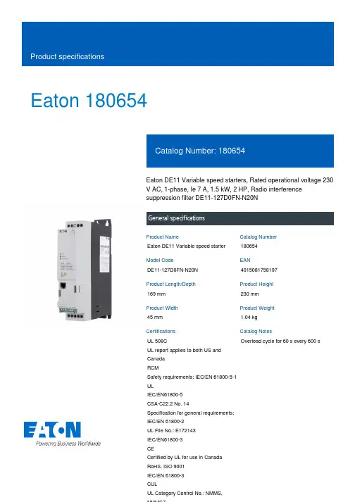
Eaton 180654Eaton DE11 Variable speed starters, Rated operational voltage 230 V AC, 1-phase, Ie 7 A, 1.5 kW, 2 HP, Radio interference suppression filter DE11-127D0FN-N20NGeneral specificationsEaton DE11 Variable speed starter 180654DE11-127D0FN-N20N 4015081758197169 mm 230 mm 45 mm 1.04 kg UL 508CUL report applies to both US and Canada RCMSafety requirements: IEC/EN 61800-5-1 ULIEC/EN61800-5 CSA-C22.2 No. 14Specification for general requirements: IEC/EN 61800-2 UL File No.: E172143 IEC/EN61800-3 CECertified by UL for use in Canada RoHS, ISO 9001 IEC/EN 61800-3 CULUL Category Control No.: NMMS,Overload cycle for 60 s every 600 sProduct NameCatalog Number Model CodeEANProduct Length/Depth Product Height Product Width Product Weight Certifications Catalog Notes240 V2.79 kVA7 A1.5 kW6.8 AIs the panel builder's responsibility. The specifications for the switchgear must be observed.230 V AC, 1-phase240 V AC, 1-phaseMeets the product standard's requirements.1.5 kW250 VMeets the product standard's requirements.-40 °C200 VRadio interference suppression filterPC connection0 Hz60 °C DX-COM-STICK3_ConnectionUpdate DX-COM-STICK3How does the internal motor protection work?Access to Parameter Level 2 Parameter Lock Load DefaultSet point settingStarting, Stopping and OperationElectromagnetic compatibility (EMC)Conformal CoatingQuick-Start-Guide DE1 (english)The OP System Bus - Parameterizing - ControlFire modeMotor data Motor Protection V/f curves Slip Compensation Connecting drives to generator suppliesI/O ConfigurationQuick-Start-Guide DE11 (english)HVAC, water/wastewater and industrial mediums - brochure Number 1 in efficiency The easiest way of variable motor speed PowerXL DE1 Variable Speed StarterDA-SW-drivesConnectDA-SW-Codesys 2 SWD for DC1 and DE1DA-SW-drivesConnect - InstallationshilfeDA-SW-DE1 ModbusRTU V1_00 LibraryDA-SW-DE11 CANopen CODESYS2 LibraryDA-SW-drivesConnect - installation helpDA-SW-Codesys 3 SWD for DC1 and DE1DA-SW-USB Driver DX-COM-STICK3-KITDA-SW-DE11 CANopen ConfigFile 210DA-SW-DE11 CANopen CODESYSV3 LibraryDA-SW-USB Driver PC Cable DX-CBL-PC-1M5DA-SW-drivesConnect USB Driver DX-COM-PCKITDA-SW-DE11 CANopen ConfigFile 203DA-SW-Driver DX-CBL-PC-3M0Product Range Catalog Drives EngineeringDrives - Product range catalogMains voltage - maxApparent power at 230 VRated operational current for specified heat dissipation (In) Rated operational power at 220/230 V, 50 Hz, 1-phase Assigned motor current IM at 440 - 480 V, 60 Hz, 150% overload 10.11 Short-circuit ratingRated operational voltage10.4 Clearances and creepage distancesOutput at quadratic load at rated output voltage - maxOutput voltage - max10.2.3.1 Verification of thermal stability of enclosuresAmbient storage temperature - minMains voltage - minFitted with:Output frequency - minAmbient operating temperature at 150% overload - max Starting current - max Application notes Brochures Catalogs200 %, IH, max. starting current (High Overload), For 1.875seconds every 600 seconds, Power section6.3 A60 °CModbus RTU, built inOP-Bus (RS485), built inCANopen®, built in2 HP300 Hz230 V AC, 3-phase240 V AC, 3-phase16 kHz, 4 - 32 kHz adjustable (audible), fPWM, Power section, Main circuitParameterization: drivesConnectParameterization: drivesConnect mobile (App) Parameterization: FieldbusParameterization: KeypadOperation (with 150 % overload)-10 °C≤ 0.6 A (max. 6 A for 120 ms), Actuator for external motor brakeDoes not apply, since the entire switchgear needs to be evaluated.7 A DA-DC-00004551.pdfDA-DC-00004556.pdfeaton-frequency-inverter-dimensions-009.eps eaton-frequency-inverter-3d-drawing-017.epsDA-CE-ETN.DE11-127D0FN-N20NIL040005ZUPowerXL DE1 variable speed starterMN040003_ENMN040018_ENMN040019_ENMZ040046_ENMN040011_ENDA-CS-de1_fs1_ip20DA-CD-de1_fs1_ip20Assigned motor current IM at 230 V, 50 Hz, 150% overload Ambient operating temperature - maxCommunication interfaceAssigned motor power at 115/120 V, 60 Hz, 1-phase Output frequency - maxOutput voltage (U2)Switching frequencyFeaturesHeat dissipation detailsAmbient operating temperature - minBraking currentNumber of HW-interfaces (serial TTY)10.6 Incorporation of switching devices and components Nominal output current I2N Certification reports DrawingseCAD model Installation instructions Installation videos Manuals and user guidesmCAD modelAssigned motor current IM at 220 - 240 V, 60 Hz, 150% overload 6.8 A10.2.6 Mechanical impactDoes not apply, since the entire switchgear needs to be evaluated.10.3 Degree of protection of assembliesDoes not apply, since the entire switchgear needs to be evaluated.Assigned motor current IM at 115 V, 50 Hz, 150% overload6.3 AProduct categoryVariable speed starterRadio interference classC2, C3: depending on the motor cable length, the connected load, and ambient conditions. External radio interference suppression filters (optional) may be necessary.C1: for conducted emissions onlyOptional external radio interference suppression filter for longer motor cable lengths and for use in different EMC environmentsAssigned motor current IM at 110/120 V, 60 Hz, 150% overload 6.8 AHeat dissipation capacity Pdiss0 WAssigned motor power at 460/480 V, 60 Hz, 3-phase2 HPNumber of HW-interfaces (RS-422)Mains current distortion120 %ProtocolMODBUSEtherNet/IPOther bus systemsCAN10.9.2 Power-frequency electric strengthIs the panel builder's responsibility.Overvoltage categoryIIIDegree of protectionIP20NEMA OtherAmbient storage temperature - max70 °CRated impulse withstand voltage (Uimp)2000 VOutput at linear load at rated output voltage - max1.5 kWLeakage current at ground IPE - max< 3.5 mA (AC-operated)< 10 mA (DC-operated)Converter typeU converterFrame sizeFS110.2.2 Corrosion resistanceMeets the product standard's requirements.Supply frequency50/60 Hz10.2.4 Resistance to ultra-violet (UV) radiationMeets the product standard's requirements.10.2.7 InscriptionsMeets the product standard's requirements.Shock resistance15 g, Mechanical, According to IEC/EN 60068-2-27, 11 msApplication in domestic and commercial area permittedYesNumber of inputs (analog)1 (parameterizable, 0 - 10 V DC, 0/4 - 20 mA)Number of phases (output)310.12 Electromagnetic compatibilityIs the panel builder's responsibility. The specifications for the switchgear must be observed.10.2.5 LiftingDoes not apply, since the entire switchgear needs to be evaluated.Number of HW-interfaces (RS-485)1Number of HW-interfaces (industrial ethernet)10.8 Connections for external conductorsIs the panel builder's responsibility.ProtectionFinger and back-of-hand proof, Protection against direct contact (BGV A3, VBG4)Number of relay outputs1 (parameterizable, N/O, 6 A (250 V, AC-1) / 5 A (30 V, DC-1))Application in industrial area permittedYesClimatic proofing< 95 average relative humidity (RH), no condensation, no corrosionConnection to SmartWire-DTIn conjunction with DX-NET-SWD3 SmartWire DT moduleYesStatic heat dissipation, non-current-dependent Pvs0 W10.9.3 Impulse withstand voltageIs the panel builder's responsibility.Voltage rating - max240 VOverload current IL at 150% overload10.5 AInput current ILN at 150% overload17.4 ANumber of HW-interfaces (RS-232)Number of inputs (digital)4 (parameterizable, 10 - 30 V DC)Rated control supply voltage10 V DC (Us, max. 0.2 mA)Cable lengthC3 ≤ 25 m, Radio interference level, maximum motor cable lengthC2 ≤ 10 m, Radio interference level, maximummotor cable lengthC1 ≤ 5 m, Radio interference level, maximum motor cable length10.5 Protection against electric shockDoes not apply, since the entire switchgear needs to be evaluated.Mounting positionVerticalMains switch-on frequencyMaximum of one time every 30 seconds10.13 Mechanical functionThe device meets the requirements, provided the information in the instruction leaflet (IL) is observed.10.9.4 Testing of enclosures made of insulating materialIs the panel builder's responsibility.Heat dissipation per pole, current-dependent Pvid0 WElectromagnetic compatibility1st and 2nd environments (according to EN 61800-3)Resolution0.03 Hz (Frequency resolution, setpoint value)Assigned motor power at 460/480 V, 60 Hz2 HPRelative symmetric net voltage tolerance10 %Equipment heat dissipation, current-dependent Pvid59 WRated operational current (Ie)7 A at 150% overload (at an operating frequency of 16 kHz and an ambient air temperature of +50 °C)Number of outputs (analog)Suitable forBranch circuits, (UL/CSA)Apparent power at 240 V2.91 kVANumber of HW-interfaces (USB)Operating modeSpeed control with slip compensationU/f controlRated frequency - min45 HzDelay time< 10 ms, On-delay< 10 ms, Off-delayNumber of outputs (digital)Power consumption59 W10.2.3.2 Verification of resistance of insulating materials to normal heatMeets the product standard's requirements.10.2.3.3 Resist. of insul. mat. to abnormal heat/fire by internal elect. effectsMeets the product standard's requirements.Number of HW-interfaces (other)Rated frequency - max66 HzVibrationResistance: According to EN 61800-5-1Short-circuit protection (external output circuits)Type 1 coordination via the power bus' feeder unit, Main circuit10.7 Internal electrical circuits and connectionsIs the panel builder's responsibility.Braking torqueMax. 30 % MN, Standard - Main circuitAdjustable to 100 %, DC - Main circuitAmbient operating temperature at 150% overload - min-10 °CRelative symmetric net frequency tolerance10 %10.10 Temperature riseThe panel builder is responsible for the temperature rise calculation. Eaton will provide heat dissipation data for the devices.Eaton Corporation plc Eaton House30 Pembroke Road Dublin 4, Ireland © 2023 Eaton. All Rights Reserved. Eaton is a registered trademark.All other trademarks areproperty of their respectiveowners./socialmedia6.3 A2 HP137 W at 25% current and 0% speed 37 W at 25% current and 50% speed 44.6 W at 50% current and 0% speed 44.9 W at 50% current and 50% speed 51.6 W at 50% current and 90% speed 62.4 W at 100% current and 0% speed 68.9 W at 100% current and 50% speed 78.4 W at 100% current and 90% speed 20 A, UL (Class CC or J), Safety device (fuse or miniature circuit-breaker), Power Wiring 0Max. 2000 mAbove 1000 m with 1 % derating per 100 mAssigned motor current IM at 400 V, 50 Hz, 150% overload Number of HW-interfaces (parallel)Assigned motor power at 230/240 V, 60 Hz, 1-phase Number of phases (input)Heat dissipation at current/speed Short-circuit protection ratingNumber of interfaces (PROFINET)Altitude。

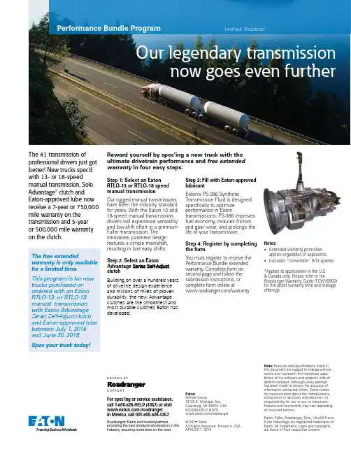
Performance Bundle ProgramThe #1 transmission ofprofessional drivers just gotbetter! New trucks spec'dwith 13- or 18-speedmanual transmission, SoloAdvantage® clutch andEaton-approved lube nowreceive a 7-year or 750,000mile warranty on thetransmission and 5-yearor 500,000 mile warrantyon the clutch.Linehaul, VocationalStep 1: Select an Eaton RTLO-13 or RTLO-18 speed manual transmissionOur rugged manual transmissions have been the industry standard for years. With the Eaton 13 and 18-speed manual transmission, drivers will experience versatility and low-shift effort in a premium Fuller transmission. The innovative, patented design features a simple mainshaft, resulting in fast easy shifts.Step 2: Select an Eaton Advantage Series Self-Adjust clutchBuilding on over a hundred years of driveline design experience and millions of miles of proven durability, the new Advantage clutches are the smoothest and most durable clutches Eaton has developed.Step 3: Fill with Eaton-approvedlubricantEaton’s PS-386 SyntheticTransmission Fluid is designedspecifically to optimizeperformance in Eatontransmissions. PS-386 improvesfuel economy, reduces frictionand gear wear, and prolongs thelife of your transmission.Step 4: Register by completingthe formY ou must register to receive thePerformance Bundle extendedwarranty. Complete form onsecond page and follow thesubmission instructions, orcomplete form online at/warranty*Applies to applications in the U.S.& Canada only. Please refer to theRoadranger Warranty Guide (TCWY0900)for the latest warranty time and mileageofferings.Notes:•Extended warranty promotionapplies regardless of application.•Excludes “Convertible” 9/13 speeds.S U P P O R TB AC K ED B YFor spec’ing or service assistance, call 1-800-826-HELP (4357) or visit /roadranger.In Mexico, call 001-800-826-4357. Roadranger: Eaton and trusted partners providing the best products and services in the industry, ensuring more time on the road.EatonVehicle Group13100 E. Michigan Ave.Galesburg, MI 49053 USA800-826-HELP (4357)/roadranger© 2017 EatonAll Rights Reserved. Printed in USA.APSL0311 0617Note: Features and specifications listed inthis document are subject to change withoutnotice and represent the maximum capa-bilities of the software and products with alloptions installed. Although every attempthas been made to ensure the accuracy ofinformation contained within, Eaton makesno representation about the completeness,correctness or accuracy and assumes noresponsibility for any errors or omissions.Features and functionality may vary dependingon selected options.Eaton, Fuller, Roadranger, Solo, UltraShift andFuller Advantage are registered trademarks ofEaton. All trademarks, logos and copyrightsare those of their respective owners.Reward yourself by spec’ing a new truck with theultimate drivetrain performance and free extendedwarranty in four easy steps:The free extendedwarranty is only availablefor a limited time.This program is for newtrucks purchased orordered with an EatonRTLO-13 or RTLO-18manual transmissionwith Eaton AdvantageSeries Self-Adjust clutchand Eaton-approved lubebetween July 1, 2016and June 30, 2018.Spec your truck today!Performance T ransmission Bundle Warranty Registration FormUse this form to activate extended warranty on:•Eaton RTLO-13 or RTLO-18 manual transmission •Eaton Advantage Series Self-Adjust clutchPerformance Bundle Warranty Instructions:1.Purchase of Eaton RTLO-13 or RTLO-18 speed manual transmission (models include RTLO-16913A, RTLO-18913A, RTLO-20913A, RTLO-16918B, RTLO-18918B, RTLO-20918B or RTLO-22918B), Eaton Advantage Series Self-Adjust clutch and Eaton-approved synthetic lubricant is required to activate extended warranty.2.Please enclose proof of purchase or repair order listing transmission and clutch along with this form to activate the warranty.3.Coverage confirmation will be sent by USPS mail.4.Convertible 9/13 speeds are not included in this program.Step 1: Enter owner/dealer informationOwner:____________________________________________________________Address:__________________________________________________________City:______________________________________________________________State/Prov:________________________ Postal Code:_____________________Phone:____________________________________________________________Email:____________________________________________________________Step 2: Enter vehicle/component informationOEM __________________________________ Date-In-Service ________________________Chassis VIN (17 characters): _______________________________________________________________________________________________________________T ransmission Model: ___________________________________________________ T ransmission Serial: ________________________________________________Clutch Part No.: ______________________________________________________ _Vehicle vocation (choose one only -– all applications qualify for this extended warranty promotion)Standard DutyRecreation Vehicleransit CoachSevere DutyHeavy Haulard TractorStep 3: Mail, fax or email this completed form with proof of purchase to:Mail: EatonFax:Email:c/o 360 Services, Inc.1-734-591-7899******************************275 E. 12 Mile Rd.Madison Heights, MI 48071Dealer Code:______________________________________________________Dealer:____________________________________________________________Dealer Contact:_____________________________________________________Dealer Contact Email:______________________________________________Address:__________________________________________________________City:______________________________________________________________State/Prov:________________________ Postal Code:_____________________Phone:____________________________________________________________S U P P O R T B A C K E D B Y© 2017 EatonCheck here for email confirmation of warranty submission (please ensure you enter your email address above).。
ContentsDescription Page Screen legends . . . . . . . . . . . . . . . . . . . . . . . . . . .2Operation . . . . . . . . . . . . . . . . . . . . . . . . . . . . . . .2Commissioning . . . . . . . . . . . . . . . . . . . . . . . . . . .2Overview . . . . . . . . . . . . . . . . . . . . . . . . . . . . . . .3Menu structure . . . . . . . . . . . . . . . . . . . . . . . . . . .5Troubleshooting . . . . . . . . . . . . . . . . . . . . . . . . . .6Retrofit installations with BLR-ACX controller . . . . . . . . . . . . . . . . . . . . . . . .7Eaton BLR-ACXQuick commissioning guide2Instruction Leaflet IL157002ENEffective July 2019Eaton BLR-ACXQuick commissioning guideEATON Screen legendsINFO Capacitor database AUTO Automatic mode MANUAL Manual mode SETUP Setup modeALARM Blinking during alarm NT Second target-pf is active EXPORT Export of active energy 1-14 Capacitor stage number indicationFigure 1. Digital displayOperationOperation of BLR-ACX is done by 4 keys .Figure 2. Operational keysSubmenus are scrolled through by pushing the ▲ (up) key or ▼ (down) key .Pressing ▼( right / Enter) key allows selection, entering the edit mode or accepts the edited values .In edit mode, the ▼(left / esc) key or ▼( right / Enter) key scroll left and right to allow setting of the appropriate digit .Outside of edit mode, the ▼(left / esc) key exits to the next higher level .Press and hold the ▼(left / esc) key for approximately 3 seconds to silence any alarms .CommissioningStep 1Upon power on the controller displays the existing power factorvalue “X.XX i” and enters the Automatic Control mode.The “i” at the end indicates an inductive power factor and would be appropriate for most installations . A “c” at the end indicates capacitive power factor and suggests reactive power export and may not be appropriate . Refer to the troubleshooting section for resolution steps .Step 2Next step is to set up the basic parameters in the controller .Press the ▼ (down) key to step through the “INFO”, “MANUAL ” and to “SETUP” mode . Press the ▼( right /Enter) key to enter the Menu 100 and program and or verify the following values .Un Nominal voltage (factory programmed, customer may verify)Ct CT -ratio (Factory set to 600, Customer to program if measurement feature is desired. Refer to Step 3). Note that this ratio is NOT needed for PF correction and isonly required for accurate measurement values. Changing the CT ratio will change the capacitor step sizes in 402 and those values will have to be re-programmed.Pt PT -ratio (factory programmed)AiStart of automatic initialization (factory programmed)PFC PF -control ON/OFF/ HOLD (factory programmed)CP1 T arget-PF (customer to program)St Switching time delay (factory programmed, customermay verify)Out Type of each stage (Auto/ Alarm/ Foff/ Fon) (factory programmed, customer may verify)Once the Menu 100 is programmed, press the ▼(left / esc) key to return to the main screen that displays the existing PF .3Instruction Leaflet IL157002ENEffective July 2019Eaton BLR-ACXQuick commissioning guide EATON OverviewBLR-ACX is factory preset to the default values shown in T able 1 .Customer to program and verify the values set to meet the specific conditions of each installation .Step 3The next step is to verify the measured values .In the main screen press the ▼( right / Enter) key to enter theMeasurement menu . The following parameters are displayed .To enable measurement values, the CT ratio has to be set .Otherwise only voltage dependent measurement values are displayed accurately . The shaded fields shown in Figure 3 are hidden and will only appear if the CT ratio is set in the menu .Step 4The final step in commissioning is to verify the working of the capacitor bank . This is done by activating the controller in manual control mode and cycling through all the available steps . Note that the steps will switch on only after the factory set capacitor stage discharge time has elapsed .After each manual operation of the stage, the PF should change in the right direction . (For example 0 .70 i >> 0 .78 i >> 0 .85 i…) .If the PF changes in the right direction, the capacitor bank has been correctly commissioned . If not, please refer to the troubleshooting section .T o switch the controller in manual control mode, press the ▼ (down) key to step through the “INFO” mode to “MANUAL ” mode. Press and hold the ▼( right /Enter)key for approximately 3 seconds until “1” displays indicating the stage number 1 is available for control.Note that in manual mode, the controller freezes the stages in their existing state (ON, OFF or HOLD). Therefore it is important to ensure that at the end of this step 4, the controller is returned back to the automatic control mode by pressing the ▼(left / esc) key to return to the main screen that displays the existing PF .After activating all available steps, one should make note of thedisplayed PF value as that reading should be greater than or equal to the target PF desired . If the displayed PF with all steps energized is less than the target PF , then the selected capacitor bank is not sized adequately to raise the PF to the desired value . The customer should either upgrade the capacity of the capacitor bank or the target PF value should be decreased to prevent “PF alarms” .4Instruction Leaflet IL157002ENEffective July 2019Eaton BLR-ACXQuick commissioning guideEATON Main screenFigure 3. Menu map5Instruction Leaflet IL157002ENEffective July 2019Eaton BLR-ACXQuick commissioning guide EATON Menu structureThe following table provides an overview about the basic and advanced programming parameters of BLR-ACX .Menu 100 is the Basic Menu . Menu 200 through 600 is for advanced users only and requires a PIN access (242) . The settings in these submenus should only be accessed and changed after consulting with Eaton T able 1.Programming mode detailed menu mapMenu FunctionDefaultCustomer settings100Quick start setupUn Nominal voltage (phase-phase) 208 V / 240 V / 480 V / 600 VCt CT-ratio 600 (corresponds to 3000:5 CT ratio)Pt VT-ratio1.7 (240 V unit) 3.7 (480 V unit) 4.7 (600 V unit)Ai Start automatic initializing N PFC Start/Stop/Hold PF-control On CP1 Target-PF 10.95i St Switching time delay60 sOutType of each step (1,2...14)Auto (for each step installed in unit), Fixed Off (for unusedCustomer6Instruction Leaflet IL157002ENEffective July 2019Eaton BLR-ACXQuick commissioning guideEATON TroubleshootingAutomatic control modeThe controller should display status “Auto,“which indicates that the controller is working in automatic mode . This is the desired mode of operation . If “Auto” is not displayed, then the power factor control is not working . Reasons for this are:• Manual mode is active• Control mode has been switched off• Temperature is too high (if temperature input is provided)• Current from the CT is less than 15 mA • Voltage is out of range•Harmonic level of voltage is too highAlarms and descriptionThe controller has an extended alarm system . When an alarm is active, the sign ALARM in the display blinks and an error code is shown on the screen . Possible error codes are shown in the table below .AlarmDescriptionU ALARM Measuring voltage is out of tolerance.1 LoALARMMeasuring current is less than 15 mA (please check CT signal and verify that CT shorting pin has been removed).1 Hi ALARM Measuring current is too high.PFC ALARM Target cannot be reached.HAr ALARM THD U alarm (harmonic alarm).StEP ALARM FltY ALARM One or more steps are defective. The defective steps are blinking together with the ALARM sign.SPLALARM/11ALARMOne or more steps have less than 70% of original size. Number of step and alarm text are blinking alternately.thi ALARMOver temperature alarm. Threshold level 2 exceeded. The steps will be switched-off step by step.OPh ALARM Maximum allowed operating hours are reached.OPC ALARM/11ALARMMaximum allowed number of switch cycles of one or more steps is reached.Ai/AbrtAbort of automatic initialization due to unsuitable load conditions.Current and voltage monitoringThe controller is equipped with current and voltage monitoring to ensure it is within its operating parameters . The controller will show “I LO” alarm if there is no measured current or the magnitude sensed is less than 15 mA . If the current is greater than 6 A, the controller will show “I Hi alarm” .If either of these alarms are displayed, check the CT current path, verifying that the correct CT ratio is selected, the CT is in the correct position, and the current input and shorting jumpers at the terminal block are removed .The allowed range of voltage depends on nominal voltage . When nominal voltage is out of range, “U Alarm” is shown . If this alarm is seen, then the setting of nominal voltage has to be adjusted . Nominal Voltage is measured and entered phase to phase .Capacitor stage databaseA step fault (“STEP / FLTY”) or step low (“SPL ”) alarm indicates problems with the sensed capacitor size . To check the capacitor stages, switch the controller into the INFO mode by pressing the ▼ (down) key . In the INFO submenu, by pressing the ▲ (up) or ▼ (down) key, the steps can be chosen and once the steps are indicated in the display, pressing the ▼() (right/enter) key displays the information for the selected steps .CC C INFO 50 kvar a ▼INFO 99 .9% a ▼OC INFO 10 .12 k a ▼i INFO AUTO a actual power of steppercentage actual to nominal powernumber of operations step type It’s possible to have capacitive steps as well as inductive steps . Ensure the steps show capacitive (“C”) kvar) .High temperature alarm1 . Replace dust filters (Catalog Number AUTOVAR6FX8) .2 . Verify proper operation of fans .3 . Verify that measured ambient temperature does not exceed40 °C (104 °F) .4 . Check for external sources of heat such as direct sunlight .PFC alarmPossible reasons could be:1 . Insufficient capacitance available or target PF set too high .2 . Capacitor stages deteriorated .3 . Capacitor stages sensed or set incorrectly (both in terms oftype (inductive or capacitive) and value (100 kvar instead of 50 kvar) .PF value incorrect, decreases as steps are added or shows X.XX“c”1 . CT polarity is incorrect .2 . CT leads are swapped .3 . CT is not mounted on A phase .Adjust the Phase-Offset menu parameter according to the following chart .CT installed phase (with respect to incoming AutoVAR bus)CT polarityController phase-offsetA Straight 90A Reverse 270B Straight 330B Reverse 150C Straight 210C Reverse 307Instruction Leaflet IL157002ENEffective July 2019Eaton BLR-ACXQuick commissioning guide EATON PF value shows unity or does not change even after steps are engaged1 . Location of CT is incorrect . Ensure that the CT is connectedelectrically ahead of the capacitor bank (at the service entrance panel or switchgear) and is not connected on the feeder that supplies power to the capacitor bank .2 . Steps have failed .Incorrect measurement values1 . Check that CT and PT ratios are programmed correctly inMenu 100 .2 . Check that Nominal voltage is programmed correctly inMenu 100 .Controller not switching on additional steps and does not reach target PFThis usually happens when the amount of capacitance available does not match the amount of kvar required . This can happen especially in low load situations when the amount of kvar required is very low compared to the smallest available step size (for example, total kvar required is 12 kvar and the smallest step size available is 60 kvar) . The controller will not bring on any step to prevent overcompensation .1 . Check that the sensed and programmed capacitor step sizes areset and match the actual value .2 . Check that the setting in 314 is set to N .3 . Check the amount of shortfall kvar (▲Q) in the measurementmenu and program this value in menu 312 .4 . If all above fails, one may need to install smaller kvar size stepsto allow the controller to switch them during low demand .BLR-ACX controller technical dataDescriptionSpecificationMeasuring and supply voltage 90–550 Vac, single-phase, 45–65 Hz, 5 VA, max. fuse 6 A VT-ratio from 1.0 to 350.0Current measuring 15 mA – 6 A, single-phase, burden 20 mohm, ct-ratio from 1 to 9600Control exits Up to 14 relays, n/o, with common point, max. fuse 6 A breaking capacity: 250 Vac / 5 A Temperature measuring By NTCAlarm contact Relay, volt free, life contact, max. fuse 6 A, breaking capacity: 250 Vac / 5 A InterfaceTTL, rearAmbient temperature Operation: –20 °C to 70 °C, storage: –40 °C to 85 °C Humidity 0–95%, without moisture condensationVoltage classII, dirt class 3 (DIN VDE 0110, part 1 / IEC 60664-1)Conformity and listing , ,Connection Pluggable terminal block, screw type max. 4 qmm CaseFront: instrument case PC/ABS (UL94-VO), Rear: metal Protection classFront: IP50, (IP54 by using a gasket), Rear: IP20Retrofit installations with BLR-ACX controllerPlease retain and follow all instructions and safety precautions during and after installation .1 . Compare voltage and current ratings of BLR-ACX with data ofmains and installation .2 . Mount the relay in the control panel with the two mounting clips .3 . Connect protection GROUND to PE connection of metal case .4 . BLR-ACX is to be connected according to the wiring diagram .5 . Ensure that the short-link for CT input signal is removed .6 . Typical wiring diagram of the controller is shown below . Thismay not match the existing installation . Please consult Eaton for retrofitting this into existing Eaton capacitor banks .Figure 4. Wiring diagramT roubleshootingSymptomCorrectionNo control powerCheck primary control fuses (three fuses located in fuse holder) and secondary fuse located on control transformer.Check disconnect or circuit breaker is ON.Check GFCI located on control panel inside cabinet.Check the reactor thermal switches status (open if operated, closed if healthy).Displayed power factor is obviously wrong ordecreases as stages engage CT secondary current is too low (check CT tap setting and plant load).CT polarity is incorrect or leads are reversed.Stages do not engage and target power factor has not been reachedConfirm that an inductive power factor is being displayed (i.e., ‘i.73’, not ‘c.73’).Confirm that the required reactive power is at least 60% of the smallest step size available for switching.Confirm availability of capacitor stages and there is no stage alarm.Confirm “AUTO” is being displayed on the controller.Blown fuse lights on front cabinet are lit (w/no blown fuses)Check 3 primary control fuses (on control panel) if check system voltage matches the nameplate voltage.Displayed power factor does not change as stages engage Review ‘Current transformer placement and connection’Controller troubleshootingRefer to “Controller setup procedure” section.Eaton1000 Eaton Boulevard Cleveland, OH 44122 United StatesEaton .com© 2019 EatonAll Rights ReservedPrinted in USAPublication No . IL157002EN / Z23003 July 2019Eaton is a registered trademark.All other trademarks are propertyof their respective owners.Eaton BLR-ACX Quick commissioning guideInstruction Leaflet IL157002EN Effective July 2019。
RRCC0015 Noviembre 2010 Cuestionario para conductores sobre AutoShift/UltraShiftFlotilla: No. de unidad de la flotilla Fecha:Concesionario: No. de RO Enviar por fax al: 269-746-6965Enviar por correo electrónico a:******************1. Describa qué sucedió (informe todas las observaciones no mencionadas más adelante):2. Si el problema se presenta al girar la llave por primera vez, pase a la pregunta número 83. ¿Las RPM del motor aumentan y disminuyen algunas veces en un esfuerzo de hacer un cambio?SíNo No lo séNDEn caso afirmativo:a) ¿Qué velocidades está tratando de cambiar la transmisión?Encierre en un círculo todas las que apliquen o describan1-2 4-5 5-6 6-7 9-10 10-11 11-12 17-18b) ¿Hace la transmisión el cambio eventualmente?SíNo No lo séNDc) ¿Regresa la transmisión a la velocidad desde donde está tratando de hacer el cambio?SíNo No lo séNDEn caso negativo:a) ¿En qué velocidades se atasca la transmisión?Encierre en un círculo una o más a continuación1 2 3 4 5 6 7 8 9 10 11 12 13 14 15 16 17 18b) ¿Puede pasar al modo Manual y hacer el cambio de velocidad?SíNo No lo séND4. ¿Tiene que detener el camión cuando se presenta un problema?SíNo No lo séND5. ¿Encontró neutral la transmisión?SíNo No lo séND6. ¿Tiene que apagar el camión en cambio de velocidad?SíNo No lo séND7. ¿Encontró neutral la transmisión después de volver a conectar la llave?SíNo No lo séND8. ¿Arranca el motor con la llave?SíNo No lo séND9. ¿Qué marca el indicador de velocidades cuando se presenta el problema?Encierre en un círculo una o más a continuación- un guión - - dos guiones número de velocidad destellante número de velocidad sin destellarF destellante flechas hacia abajo flechas hacia arriba CA destellante pantalla en blanco10. ¿Se enciende la luz de servicio de la transmisión, la luz de verificación del motor o la luz de los frenosantibloqueo cuando se presenta el problema?Servicio de latransmisiónVerificacióndel motorABS Ninguna11. ¿Se presenta el problema cuando la transmisión está fría, caliente o ambas?Fría Caliente Ambas ND12. ¿Se presenta el problema cuando funciona en climas húmedos, climas secos o ambos?Húmedo Seco Ambos ND13. ¿Cuántas veces al día, a la semana o al mes se presenta el problema? Número de veces _________Veces al día Veces a lasemana Vecesal mes ND14. ¿Cuánto tiempo ha tenido el camión este problema?Primera vezÚltimas 2semanas ÚltimomesVariosmeses15. ¿Cuánto tiempo ha conducido este camión?Días Semanas Meses Años16. Enumere todos los problemas conocidos que haya tenido el camión en el pasado: Encierre uno o más enun círculo o describa los problemas conocidostransmisión motor sistema de enfriamiento ABS Sistema eléctrico OEM recibió un rayoaccidente sufrió una inundación17. ¿Cuánto tiempo ha transcurrido desde que se presentó cualquiera de los problemas conocidosmencionados?Primera vez Últimas 2semanasÚltimomesVariosmeses。
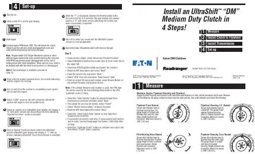
t f i h S a r t l U n a l l a t s n I ™” M D “Medium Duty Clutch in 4 Steps! :l a i r e t a M e c n e r e f e R LMT-1314C e clutch. h t k c o l n u l l i w s i h T . 0 0 5 1 e v o b a M P R e n i g n e e s a e r c nt code and n e m e g a g n e s i d h c t u l c a t e s l l i w s i h t od o te r u l i a . r a e go t n i o g t o n l l i w n o i s s i m s n a rt e h t d n a e d o c : e t o N other r o s n o i t po e c n a ts i se R r e p m a T S S V e l b a m m a r g o r P g the required n i hc a e r t n e ve r p h c i h w s t i m i l d e ep s e n i g n e l a i c i f i t r a t of the clutchn e m e g a g n e s idr ep o r p t n e v e r p y a m M P R 0 0 5 1e options may need to s e h T .n o it a l l a t s n i l a i t i n i r e t f a e c i v e d g n i k c o l locking device is disengaged. h- c t u l c e h t r e t f a l i t n u d e l b a s i d e b with Service Rangerh c t u l c e t a r b i l a c e R / a t a d h c t u l c e v a . n o y e k n r u n the gear display. o s i ” N “ d i l o s a y f i r e . e n i g n e t r a t SNote: If Ser v iceRanger is available, proceed to Step 12.“Special Functions” mode is activated.arrows indicating UltraShift Touch Point Resent is selected).After the “1” is displayed, depress the throttle pedal to the floor and hold for 3-5 seconds (the gear display will change back to a “0” with down arrows indicating the routine has been successfully completed.Key off or select any mode and the UltraShift systemreturns to normal operation. Gen 3• Using se rvice ranger, select “Advanced Product Function” • Select UltraShift transmission model (Gen 3) from menu tree in the upper left.• Select the V PA/SnapShot Utility and launch the function. • Read the APF description and select “Next” • Enter the vehicle info and select “Next.”• Select “V PA” from the dropdown “Data Source” field.• Enter an output file name and location using Browse Button or use default filename and location shown.Note: If the default filename and location is used, the VPA data file will be saved to the ServiceRangerData folder in the VPA subfolder on the C:\drive.• Select the “start transfer” button to download data from transmission controller and then select “Next.” • The output file can now be viewed, select “Finish” • Select “Clutch Se rvice Utility” to launch function. • Read the APF description then select “Next.”• Select the “Clear Clutch Data” button to clear data from transmission controller.• If successful proceed to next step, if unsuccessful exit function and re-enter. Contact Roadranger Call Center 1-800-826-4357 for help.• Select the “Calibrate Clutch” button to calibrate new cultch and then Select “Finish” when complete.le e h w y l F d n a g n i s u o H l e e h w y l F e n i g n E e r u s a e M e v o m e R . r a e w h c t u l c e r u t a m e r p e b l l i w e r e h t r o s n o i t a c if i c e p s e s e h t t e e m t s u m l e e h w y l f d n ag n i s u oh l e e h w y l f e ni g n E : g n i w o l l o f e h t k c e h c d n a r o t a c i d n i l a i d a e s U . y r d d n a n a e l c e b t s u m s e c a f r u s t c a t n o c e g u a g l l A . g n i r a e B t o l i P d l o t u o n u R e c a F l e e h w y l F o t e s a b r o t a c i d n i l a i d e r u c e S t u P . e c a f g n i s u o h l e e h w y l f h t i w t c a t n o c n i r e g n i f e g u a g r e t u o e h t r a e n e c a f l e e h w y l f e n o l e e h w y l f e t a t o R . e g d e s i t u o n u r m u m i x a M . n o i t u l o v e r .) m m 0 2 . ( " 8 0 0 . Runout e r o B g n i r a e B t o l i P o t e s a b r o t a c i d n i l a i d e r u c e S n o i t i s o P . e c a f g n i s u o h l e e h w y l f s t c a t n o c t i t a h t o s r e g n i f e g u a g e t a t o R . e r o b g n i r a e b t o l i p . n o i t u l o v e r e n o l e e h w y l f " 5 0 0 . s i t u o n u r m u m i x a M . ) m m 3 1 . (. D . I g n i s u o H l e e h w y l F o t e s a b ro t a c i d n i l a i d e r u c e S r e g n i f e g u a g t u P . t f a h s k n a r c g n i s u o h l e e h w y l f t s n i a g a e n o l e e h w y l f e t a t o R . D . I t o l i p t u o n u r m u m i x a M . n o i t u l o v e r .) m m 0 2 . ( " 8 0 0 . s i e c a F g n i s u o H l e e h w y l F o t e s a b r o t a c i d n i l a i d e r u c e S . e g d e r e t u o e h t r a e n l e e h w y l f t c a t n o c n i r e g n i f e g u a g t u P l e e h w y l f f o e c a f h t i w e n o l e e h w y l f e t a t o R . g n i s u o h t u o n u r m u m i x a M . n o i t u l o v e r .) m m 0 2 . ( " 8 0 0 . s i Eaton Corporation • Truck Components OperationsP .O. Box 4013 • Kalamazoo, MI 49003 USA ww ©2011 Eaton Corporation • All rights rese rved.Printed in USA. CLMT1320 0911 WPEaton DM ClutchesMore time on the roadCheck T ransmission For W ear Replace any worn components.the disc.Remove the guide studs and install the two remaining mounting bolts. Tighten the clutch mounting bolts in a crossing pattern as on any other clutch and torque to3/8"-16 UNC X 2.25" with lockwashers, minimum grade 5 covered by the Hex Cap Screw specification under ASME B18.2.1 1996. Torque to 30 - 35 lbs. ft.。
使用说明书S9(Synchro-9)双中间轴全同步器重型变速器2010-2-20警示标志警告和注意以下详细的驾驶员操作指南将避免您的人生安全受到伤害。
在操作变速器之前请仔细阅读本驾驶员操作指南的全部内容。
在车辆启动前,驾驶员应坐在驾驶员座位上,将变速杆置于空档位置,并使用手刹装置。
在停放车辆或当发动机运转时离开驾驶室时,应将变速杆置于空档位置,并使用手刹装置同时使用枕木固定车轮。
以下详细的驾驶员操作指南将避免操作失误引起的变速箱的故障和损坏。
当车辆空气系统的压缩空气未达到正常的气压的情况下,禁止松开手刹装置。
当车辆在斜坡上时,禁止将档位换入空档中。
目录S9概述S9介绍 4 型号命名 4 换档手柄和指示牌操纵杆位置标签 5 档位位置标签5驾驶指南注意事项6保养和维护识别铭牌7使用保养8预防性保养维护12S9概述S9介绍S9(Synchro-9)是一款双中间轴全同步器重型变速器,它由9个前进档和一个倒档组成。
整体采用了主副箱组合设计,主箱是手动操纵包含5个前进档速比和1个倒档速比,副箱是气动操纵包含2个速比。
型号命名(公制)E T (O) -16 10 9 A换档手柄和指示牌操纵杆位置标签双H操纵杆位置标签双H操纵杆位置示意图双H换档位置标签驾驶指南注意事项换档时,离合器必须彻底分离,变速杆应挂档到位。
车辆挂低档(爬坡档)或倒档时,应先停车,在挂档,以免损坏变速器内部的零件。
挂倒档时,需使用较大的选档力以克服倒档锁的阻力。
换档时,离合器必须彻底分离,变速杆应挂档到位。
由4档换5档(或由5档换4档)时,应有意识地稍停片刻,以利于副变速器完成高低档位区间的转换。
当变速器从低档区向高档区(或反之)换档时,不要跳档操作,否则将引影响副箱同步器的使用寿命。
车辆下坡时,禁止变换高、低档位区。
根据道路情况,采用1档或2档起步。
车辆起步前,应首先解除制动。
采用断气制动的车辆在接通制动阀后,必须待气压上升到解除制动所需要的压力时,方可挂档起步。
更多信息请到RoadRanger网站查询:警告标识本手册中的有些段落会有DANGER,WARNING,或者CAUTION的标识。
这些段落包含特殊的安全信息,进行操作之前必须通读理解这些信息,并在操作过程中留意。
DANGER:该标识表明如果不遵守规定的操作程序,会有人员严重受伤或死亡的可能。
WARNING:该标识表明有直接的危险存在,如果不遵守规定的操作程序,会有人员严重受伤的可能。
CAUTION:该标识表明如果不遵守规定的操作程序,会导致车辆损坏或财产损失。
注意:在操作过程中注意细节有助于故障诊断或系统维修。
操作变速器前通读本手册车辆启动前驾驶员要坐在驾驶员座椅上,按空档(N),拉起手刹如果启动发动机时变速器没有在空档位(N),立刻检查车辆你在操作车辆过程中如果要停车或暂时下车,一定要按空档(N),拉起手刹,并在车轮处加塞块出于安全的原因,变速器挂档前请踩住刹车踏板进行任何焊接操作前,24V电池的正极和负极必须完全断开高压警告标识使用二氧化碳或者干粉灭火器,电池盒中的电池为锂离子电池高压线束为橙红色,并在接头位置有警告标签所有Eaton的柴油混合动力车辆在车内都有高压元件位置图不要切断或移动橙红色高压线束,参见高压元件位置图不要切割或打开电池盒,参见高压元件位置图不要切割或打开逆变器,参见高压元件位置图本手册中的紧急关机程序会说明如何在紧急情况时关闭电源警告标识 (i)紧急关机程序 (1)发生火灾时的紧急程序 (2)发生交通事故时的紧急程序 (2)高压元件特征 (3)换档按钮说明 (4)启动和停车 (5)倒档 (6)前进档-自动换档模式 (6)前进档-手动换档模式 (6)低速档 (7)再生制动模式 (7)一般型号信息 (8)故障排除 (9)档位卡死 (9)正确润滑 (10)正确的油面高度: (11)混合动力冷却系统 (11)紧急关机程序方法1:关钥匙(推荐)发动机会关闭仪表盘会关闭混合动力系统会关闭混合动力电池只在电池盒中有电方法2:断开24V电池发动机会关闭仪表盘会关闭方法3:拔掉混合动力控制器的保险丝(30A)混合动力系统会关闭混合动力电池只在电池盒中有电这些程序只适用于紧急情况,车辆维修时请参见《维修手册》中的相关内容发生火灾时的紧急程序如果车辆发生火灾:1.使用二氧化碳或者干粉灭火器,电池盒中的电池为锂离子电池高压线束为橙红色,并在接头位置有警告标签所有Eaton的柴油混合动力车辆在车内都有高压元件位置图不要切断或移动橙红色高压线束,参见高压元件位置图不要切割或打开电池盒,参见高压元件位置图不要切割或打开逆变器,参见高压元件位置图发生交通事故时的紧急程序如果条件允许,请把车推到路肩上并停车1.拉手刹2.按空档(N)3.关钥匙4.如果安全的话,下车高压线束为橙红色,并在接头位置有警告标签所有Eaton的柴油混合动力车辆在车内都有高压元件位置图不要切断或移动橙红色高压线束,参见高压元件位置图不要切割或打开电池盒,参见高压元件位置图不要切割或打开逆变器,参见高压元件位置图高压元件特征所有的高压线束为橙红色,并在接头位置有警告标签;每一个高压元件都有明显的警告或危险标识。
![变速箱维修拆装 伊顿[上海]S9和S13挡变速箱维修工具操作手册](https://uimg.taocdn.com/768e7cffaeaad1f346933f6b.webp)
Pre-Authorized Warranty Repair Guideline RWRG0060Page 1RWRG0060 - Auxiliary Case to Main Case Gasket LeakSymptom(s)•Oil leak toward rear of transmissionCauseAuxiliary case gasket may leak. Slight dampness or an oil stain would not justify a repair but if wetness or a drip is noticed re-pairs should be made.Repair GuidelineThe shift tower, shift bar housing and auxiliary section must be removed. All gasket surfaces should be cleaned and new gas-kets installed.Warranty Parts•Gaskets•Top off oil (up to $30 if needed)•Strap bolts (if needed)For part numbers refer to the Eaton InfoRanger site, , or a current IPL.Warranty Labor•Shift bar housing R&R per OEM guideline •Auxiliary section R&R per OEM guidelineWarranty Coding•Part: 4302248•Complaint: Oil leak •Failure: LeaksWarranty Claim FilingReference warranty coverage. File pre-authorized warranty claim through appropriate OEM or through Direct Pay. Refer-ence guideline number RWRG0060 in warranty claim text.Note: Repairs that exceed parts and labor parameters cannot be pre-authorized.Filing through Direct PayClick here for Direct Pay submission guidelines and claim forms:Parts DispositionParts can be scrapped.Warranty DisclaimerIf the failure is not the result of an accident, damage, negli-gence, abuse or misuse, improper installation or maintenance or any other conditions described in the Limits and Exclusions section of W arranty Manual TCW Y0600, available on , then Roadranger will treat the condition as cov-ered under its warranty. However, this conclusion does not necessarily mean that a defect in fact exists. In all cases, Road-ranger shall make the final determination and interpretation as to the warrantability of the Product.。
FO-14E309ALL -VMSFO-16E309ALL -VMSFO-17E309ALL -VMSUltraShift ® PLUS Automated T ransmissions Vocational Multipurpose Series (VMS) Giving you control when you need it mostEaton Sales and Marketing Office 145, Off Mumbai-Pune Road Pimpri, PUNE - 411 018, INDIA Tel: +91 20 30611565Features:•Fully automated two-pedal design (no clutch pedal)• Electronic Clutch Actuator (ECA) provides smooth engagement• Safety features include Auto Neutral and Intelligent Hill Start Aid, which prevents roll-back and roll-forward on grades using foundation wheel brakes while launching• Automatic, Manual and Low modes offer driver full control• Creep mode• On/Off-highway performance design• Paired to the highest torque engines available today with torque capacities ranging from 1424 Nm through 3050 Nm• World class startability and ratio coverage Note: The Company reserves the right to alter this specification at any time without notice. © 2015 Eaton, All Rights Reserved, Printed in India, Publication No. TRSLUSP VMS, September 2015For low-speed maneuverability, a necessity for challenging worksites, the UltraShift PLUS Vocational Series of automated transmissions is the ultimate transmission choice. Through extended low and reverse gear ratios, it provides the lowest ground speed for curbing, creeping, spreading, and paving.For highway construction and tipper operations, it is designed with deep reduction and fast, flexible reverse gearing. And the patented shift logic and controls within every UltraShift PLUS constantly adapt based on changes in load, grade, and power, to maximize efficiency.Gear Selection Logic and low-speed maneuverability make UltraShift PLUS the smartest transmission for the job.Driver Interface: Simple and Intuitive • Manual override • Low mode • Button shifting in Drive, Reverse, Manual and Low modes Driveline Protection Features:• Stall prevention • Engine overspeed protection • Clutch abuse protection • Auto gear select • Hill Start Aid * Dry weight, including clutch ** Standard installed length 1+200 lb-ft. [271 Nm] in top two gearsT otal Installed Specifications:Image is only representative。
Eaton® Fuller®T ransmission Rebuild & Overhaul Kits Stay GenuineSave big when compared to buying the components separately. Plus, you'll get everything you need with one part number instead of spending time and effort identifying individual parts required.All kits come with one-yearwarranty.**Backed by the RoadrangerNetwork – the nation’s lead-ing support system for drive-train components – providingunequaled protection, support,and training from experiencedprofessionals.For a complete, up-to-date kitcontent list by model,Master Rebuild KitsComprehensive kit includescomponents to completelyoverhaul a transmission.Basic Overhaul KitsWhen a new input shaft andsliding clutch are needed for along lasting, trouble free,overhaul.Basic Rebuild KitsDesigned for transmissions withlittle wear and tear and havereusable components.KIT MASTER BASIC BASICCONTENTS* REBUILD OVERHAUL REBUILDO-Rings X X XBearings X X XSnap Ring X X XSprings X X XShim Kit X X XOil Seal Kit X X XGasket Kit X X XSliding Clutch X XInput Shaft X XDrive/Overdrive Gears XBreather XHose Assemblies XClutch Brake XAir/Filter Regulator XSplitter and Range Valve X(where applicable)Front Bearing Cover XSynchronizer Assembly XShift Fork XMiscellaneous Washers X* Kit contents may vary based on transmission model and kit.** Please refer to the Roadranger Warranty Guide TCWY0900 for the latestwarranty time and mile offerings.EatonVehicle Group13100 E. Michigan Ave.Galesburg, MI 49053 USA800-826-HELP (4357)/roadranger© 2015 EatonAll Rights Reserved. Printed in USA.APSL0490 0415For spec’ing or service assistance,call 1-800-826-HELP (4357) or visit ourweb site at .In Mexico, call 001-800-826-4357.Roadranger: Eaton and trusted partnersproviding the best products and services in theindustry, ensuring more time on the road.S U P P O R TB AC K ED B YReplace with only genuine Eaton parts for performance,durability and warranty assurance.•Eliminate cross-reference mistakes and get the right part the firsttime, every time.•Maintain your warranty with genuine components.•Pick Eaton, and get legendary Roadranger support for More TimeOn The Road.。
Success Story:James Hansen Forest Products, LLC Market ServedVehicle/TransportationEaton UltraShift® transmission is really cutting itfor veteran log haulerPLUS“It allows you to concentrate on driving and the conditions around you…You do not have to think about what gear you should be in. UltraShift PLUS does all of the thinking for you. It’s much safer and easier.”Jim Hansen, owner/operator,James Hansen Forest Products, LLC BackgroundOwner operator Jim Hansen'swork week begins around 6 a.m.on Monday when he gets intohis 2015 Western Star truck witha six-axle tri-drive tractor and afive-axle trailer. Hansen travels200 miles from his home upto northern Michigan to collectsome 100,000 pounds of logs.That same day, once the logsare loaded and secured, Hansentypically travels another 200miles to deliver the wood tomills in southeastern andcentral Michigan.Instead of heading home afterthat, he sleeps in his truck tosave time and money. Hansendoes the same routine, occa-sionally making shorter runseach day, until Friday nightwhen he returns home forthe weekend.“Through the years, many truck-ers have come and gone, notrealizing the daily hard work andchallenges this work requires.It’s not something that’s foreveryone. It takes a special kindof person to live this kind of life,”says Hansen.The 59-year- old trucking industryveteran has been doing this for42 years.ChallengeSome weeks are harder thanothers, depending on the driv-ing conditions that range fromcongested urban traffic to hilly,muddy, and sometimes snowcovered off-road terrains thatHansen encounters getting inand out of the north woods.The huge payloads take skill andknowledge of the time of yearand types of wood to make surethe heavy hauls can be loadedand transported legally andefficiently.Often the mills have to sendbulldozers in to remove treesand stumps and carve out amakeshift road for Hansen. It’snot unusual for those samebulldozers to give Hansen anoccasional push so he can getthrough all of the mess.“The rough driving conditions asfar as getting the logs out of thebush can be especially demand-ing physically and mentally,” saysHansen. “Of course, it was a lotmore demanding 40 years ago.The equipment today is muchbetter than it was in the past,but it’s still very hard work.”Location:Lachine,MichiganSegment:LoggingChallenge:Safely and efficiently transportingextra heavy truck loads of timberwhile negotiating a variety ofdemanding road conditions.Solution:Eaton’s UltraShift PLUS MultipurposeExtreme Performance (MXP)TransmissionResults:The transmission’s grade sensing,weight computation and shiftdecisions provides safe, fuel efficientand driver-friendly performance.Contact Information:EatonVehicle Group13100 E. Michigan Ave.Galesburg, MI 490531-800-826-HELP (4357)/roadrangerS U P P O R TB AC K ED B YHansen was joined by his wife, Annette, after having his log rack and loader installed on his new Western Star truck. Annette also has a commercial driver’s license and spent 15 years in the logging industry.The cost of diesel fuel is also one of Hansen’s top challenges, so any fuel consumption gains he can find are more than wel-comed. With downtime being another factor that can chop into his productivity, he’s not shy about keeping up-to-date with the newer technologies in truck equipment and components to help ensure the best possible uptime.SolutionHansen cites one relatively new component as being particularly helpful with his recent success. After consulting with a fellow logger who works in even more demanding conditions of Michigan’s Upper Peninsula, and researching the product himself, Hansen decided to invest in a new Eaton UltraShift PLUS automated transmission for his Western Star truck.“A friend of mine bought a new truck about a year ago with an UltraShift PLUS in it,” says Hansen. “After listening to what he had to say about how it per-formed, I decided I wanted one. It was the wisest decision I’ve ever made. I love it.”The lucky recipient of Hansen’s affection is an UltraShift PLUS MXP (Multipurpose Extreme Performance) model. With 18-speeds and 2,250 lbs.-ft. torque capacity, the transmis-sion has virtually no payload weight limit – including the 158,000 pounds of combined vehicle weight that Hansen carries around every week. The transmissions are part of the UltraShift PLUS Performance Series, all of which employ grade sensing, weightcomputation and driver throttle commands to make intelligent shift decisions for optimum per-formance. The fully automated two-pedal transmissions can be paired with the highest torque engines available in the trucking industry.His transmission has 18 forward and four reverse speeds and an overall ratio of 20:1. Safety features include auto neutral and Intelligent Hill Start Aid, which prevents roll-back and roll-for-ward while launching on grades using foundation wheel brakes. Automatic Manual and Low modes offer drivers optimum vehicle control.Result“I’ve always been a fan of Eaton,” adds Hansen. “My previ-ous truck had an Eaton 18-speed manual transmission and it gave me a million miles of reli-able performance, but this new UltraShift PLUS has just made my job so much easier.“I mean it’s doing all of the work for me. When I’m coming out of the bush, through big hills and all types of road conditions, it knows when to shift and it shifts properly.”He went on to cite the transmis-sion’s favorable impact in making him a safer and better fuel consuming driver.“It allows you to concentrate on driving and the conditions around you,” he adds. “That’s really helpful in heavy traffic and through the city when I am fully loaded. Y ou do not have to think about what gear you should be in. UltraShift PLUS does all of the thinking for you. It’s much safer and easier.”Hansen is currently averag-ing about 4.1 miles per gallon, which he claims is very good for a heavy hauler and about the same as he was getting with his former vehicle that had two instead of three drive axles. Hansen credits his local Eaton Roadranger with an important assist.“An Eaton factory technician phoned me one day and said he wanted to ride along with me with a load on. We drove the full load around the loop of Lansing, Michigan, and he asked me to take a look at a new soft-ware shifting program. Then he used the ServiceRanger 4 tool to update my transmission.“Just like that it was shifting smoother and faster. Later, I discovered, I was getting bet-ter fuel economy. He was very knowledgeable and passedalong very helpful information. I was really glad I met with him.”After the sale support has been a longtime mainstay at Eaton with the company’s more than 200 Roadranger field members servicing all facets of the North American trucking industry. Over the years, many in the industry have cited the commit-ment to service as a factor that keeps Eaton a cut above the competition.S U P P O R TB AC K ED B YFor spec’ing or service assistance, call 1-800-826-HELP (4357) or visit /roadranger . In Mexico, call 001-800-826-4357.Roadranger: Eaton and trusted partnersproviding the best products and services in the industry, ensuring more time on the road.EatonVehicle Group13100 E. Michigan Ave.Galesburg, MI 49053 USA 800-826-HELP (4357)/roadranger © 2015 EatonAll Rights Reserved. Printed in USA.TRSL2547 0515Note: Features and specifications listed in this document are subject to change without notice and represent the maximum capa-bilities of the software and products with all options installed. Although every attempt has been made to ensure the accuracy of information contained within, Eaton makes no representation about the completeness, correctness or accuracy and assumes no responsibility for any errors or omissions. Features and functionality may vary depending on selected options.Eaton, Fuller, Roadranger, Solo and UltraShift are registered trademarks of Eaton. All trade-marks, logos and copyrights are those of their respective owners.。
更多信息请到RoadRanger网站查询:警告标识本手册中的有些段落会有DANGER,WARNING,或者CAUTION的标识。
这些段落包含特殊的安全信息,进行操作之前必须通读理解这些信息,并在操作过程中留意。
DANGER:该标识表明如果不遵守规定的操作程序,会有人员严重受伤或死亡的可能。
WARNING:该标识表明有直接的危险存在,如果不遵守规定的操作程序,会有人员严重受伤的可能。
CAUTION:该标识表明如果不遵守规定的操作程序,会导致车辆损坏或财产损失。
注意:在操作过程中注意细节有助于故障诊断或系统维修。
操作变速器前通读本手册车辆启动前驾驶员要坐在驾驶员座椅上,按空档(N),拉起手刹如果启动发动机时变速器没有在空档位(N),立刻检查车辆你在操作车辆过程中如果要停车或暂时下车,一定要按空档(N),拉起手刹,并在车轮处加塞块出于安全的原因,变速器挂档前请踩住刹车踏板进行任何焊接操作前,24V电池的正极和负极必须完全断开高压警告标识使用二氧化碳或者干粉灭火器,电池盒中的电池为锂离子电池高压线束为橙红色,并在接头位置有警告标签所有Eaton的柴油混合动力车辆在车内都有高压元件位置图不要切断或移动橙红色高压线束,参见高压元件位置图不要切割或打开电池盒,参见高压元件位置图不要切割或打开逆变器,参见高压元件位置图本手册中的紧急关机程序会说明如何在紧急情况时关闭电源警告标识 (i)紧急关机程序 (1)发生火灾时的紧急程序 (2)发生交通事故时的紧急程序 (2)高压元件特征 (3)换档按钮说明 (4)启动和停车 (5)倒档 (6)前进档-自动换档模式 (6)前进档-手动换档模式 (6)低速档 (7)再生制动模式 (7)一般型号信息 (8)故障排除 (9)档位卡死 (9)正确润滑 (10)正确的油面高度: (11)混合动力冷却系统 (11)紧急关机程序方法1:关钥匙(推荐)发动机会关闭仪表盘会关闭混合动力系统会关闭混合动力电池只在电池盒中有电方法2:断开24V电池发动机会关闭仪表盘会关闭方法3:拔掉混合动力控制器的保险丝(30A)混合动力系统会关闭混合动力电池只在电池盒中有电这些程序只适用于紧急情况,车辆维修时请参见《维修手册》中的相关内容发生火灾时的紧急程序如果车辆发生火灾:1.使用二氧化碳或者干粉灭火器,电池盒中的电池为锂离子电池高压线束为橙红色,并在接头位置有警告标签所有Eaton的柴油混合动力车辆在车内都有高压元件位置图不要切断或移动橙红色高压线束,参见高压元件位置图不要切割或打开电池盒,参见高压元件位置图不要切割或打开逆变器,参见高压元件位置图发生交通事故时的紧急程序如果条件允许,请把车推到路肩上并停车1.拉手刹2.按空档(N)3.关钥匙4.如果安全的话,下车高压线束为橙红色,并在接头位置有警告标签所有Eaton的柴油混合动力车辆在车内都有高压元件位置图不要切断或移动橙红色高压线束,参见高压元件位置图不要切割或打开电池盒,参见高压元件位置图不要切割或打开逆变器,参见高压元件位置图高压元件特征所有的高压线束为橙红色,并在接头位置有警告标签;每一个高压元件都有明显的警告或危险标识。
电池盒内有一个高压保险丝对高压电池进行保护从电池盒内引出的高压线都有继电器控制,钥匙关闭状态下为开路,只在电池盒内有高压所有的高压线束和车架都是绝缘的车辆运行时,漏电检测功能可以时刻检测高压系统是否有漏电,如果发生故障,仪表的黄灯点亮,高压系统关闭电池盒上安装的惯性开关在发生交通事故时会自动打开,切断高压输出高压直流线束有互锁装置,接头松动或断开时会关闭高压系统高压交流线束会持续检测高压线和车架之间是否短路,如果钥匙打开时有故障,发动机不能启动;如果行车中有故障,仪表盘的红灯会闪烁换档按钮说明R :变速器挂倒档,挂倒档前车速必须低于2km/hN :变速器挂空档D :选择默认的起步档位,行车过程中自动换档Manual :保持当前档位或者通过升档/降档按钮选择合适的档位,手动换档模式在任何时候都可以切换Low :变速器尽快降档以实现最大的发动机制动,尽晚升档以实现发动机最大功率升档/降档按钮:手动模式时进行升档或降档,注:变速器会自动进行升档或降低以防止发动机超速或熄火倒档空档前进档-自动换档模式前进档-手动换档模式低速档故障指示灯手动升档手动降档启动和停车启动1.将钥匙转到ON,使混合动力系统上电2.确认手刹拉起,档位显示为N3.启动发动机注:发动机启动会有一定的延迟注:本车的主启动系统混合动力驱动电机,启动时会很有力。
发动机上安装的24V启动电机为备用启动系统,当混合动力系统关闭或电池电量不够时,该车会自动转到备用启动系统,此时和传统车没有任何区别4.踩住制动踏板5.松开手刹6.在换档按钮上选择合适的档位7.慢慢松开制动踏板,车辆会怠速行驶,车速小于8km/h注:本车会根据电池的荷电状态自动选择电机驱动或者发动机驱动,在电机单独驱动时,发动机会保持在怠速状态。
电池并不能将车辆驱动很远的距离。
因此当发动机发生故障时,车辆应该尽快移动到安全的地方。
变速器没有坡道保持能力,因此在斜坡上停车时必须使用制动踏板。
如果长时间使用变速器进行坡道保持,离合器发热会导致离合器提前失效。
停车1.在换档按钮上选择空档注:关钥匙前一定要确认变速器挂入空档,紧急情况出外2.拉手刹3.关钥匙,发动机会关闭倒档选择倒档前车辆应该停车,如果司机在车速高于3km/h时选择倒档,只有在车速低于3km/h时,变速器才会进行挂档。
前进档-自动换档模式本车默认起步档位为2档,车辆停车时,可以通过使用升档/降档按钮来选择起步档位。
选定的起步档位在关钥匙之前一直有效。
在自动换档模式下,所有的升降档操作都是自动完成的。
前进档-手动换档模式司机可以在任何时候选择手动换档模式,比如厂区内行驶,过铁轨或爬坡等。
起步时选择手动换档模式和自动换档模式一样,驾驶员可以用同样的方法选择起步档位当驾驶员不进行换档时,变速箱将一直保持在起步档位,除非有特别注明的情况出现通过使用升档/降档按钮可以选择需要的档位行车中从D或Low选择手动换档模式将保持当前档位而不进行自动换档,除非有特别注明的情况出现同样,驾驶员也可通过使用升档/降档按钮选择需要的档位注:变速箱会自动升档或降档以防止发动机转速过高或者熄火。
车辆停车时,变速箱会自动选择到起步档位。
低速档司机可以在任何时候选择手动换档模式,比如下长坡,或者紧急刹车。
起步时选择低速档起步档位为1档且不能改变行车过程中变速器自动换档行车中从D或Manual选择低速档升档和降档的转速都升高,以实现最佳的动力性能和发动机制动性能行车过程中变速器自动换档再生制动模式混合动力系统会使用再生制动给混合动力电池进行充电。
车辆滑行或者踩制动踏板时,混合动力系统就会给电池充电。
再生制动时,车辆会有轻微制动的感觉。
电池充满后,混合动力系统会自动关闭再生制动功能。
这种情况在下长坡连续制动时会出现。
在任何时候都可以使用制动踏板实现最大的制动效能。
当ABS起作用时,再生制动功能会自动关闭。
一般型号信息术语标签位置所有的Eaton®Fuller®变速器都使用型号和序列号进行识别,这些信息刻印在变速器的识别标签上。
不要摘掉或损坏变速器识别标签下面空白部分用来记录变速器的识别信息,定购零件或要求维修前请提供相关信息。
故障排除如果混合动力系统发生故障,驾驶员需要完成以下4项工作:1.记录发生故障时的驾驶条件2.记录发生故障时车辆的状态,如档位、发动机转速等3.记录换档按钮上的故障指示灯和仪表盘上黄灯是否闪烁或点亮4.重启系统混合动力系统重启步骤有些时候,重新启动混合动力系统可以使故障消除。
使用以下步骤重启系统:1.确认安全以后停车2.挂空档,关钥匙3.等至少2分钟4.重新启动发动机5.如果故障依然存在,请致电Eaton服务中心档位卡死如果车辆熄火时变速箱不在空档上,就可能会出现变速箱档位卡死。
车辆下一次上电时,变速箱会试图换到空档位置。
如果成功,仪表板档位显示“N”;如果换不到空档,换档按钮的故障指示灯就会闪烁,发动机不能启动。
请参照以下步骤:1.按空档按钮,关闭钥匙至少2分钟2.踩住刹车踏板3.松开手刹4.将钥匙转到ON位置5.确认换档按钮在空档位置6.此时变速箱会试图换到空档上,你可以松开刹车踏板,以消除传动系统的扭矩。
7.一旦换到了空档,就可以启动发动机了。
如果不能换到空档,换档按钮的故障指示灯会闪烁并且发动机不能启动。
请致电EATON服务中心以获得技术支持。
正确润滑正确的润滑程序是维修保养过程的关键。
如果没有润滑或者润滑油液面不对,所有的保养程序都没办法保证变速器的正常运转。
Eaton®Fuller®的变速器都是飞溅润滑设计的。
因此严格遵守以下程序可以保证所有零件都有正常的润滑。
1.保持正确的润滑油液面,并定期检查2.遵守保养计划3.使用正确型号和等级的润滑油4.从认证的供应商处购买润滑油一定不要将齿轮油和发动机油混在一起。
齿轮油和发动机油是不兼容的,混合会导致油品失效使零件损坏。
更换不同牌号的润滑油前,所有零件都要仔细清洗。
注:请使用Eaton认证的润滑油注:润滑油中不准使用添加剂或抗磨剂正确的油面高度:请确保油面和加油口持平。
手指可以碰到油面并不代表油面高度正确。
混合动力冷却系统水箱混合动力冷却系统的水箱必须保持正确的液面高度。
冷却液类型混合动力冷却液使用特级防冻防锈液(稀释50/50),添加冷却液时必须使用同种类型的冷却液。