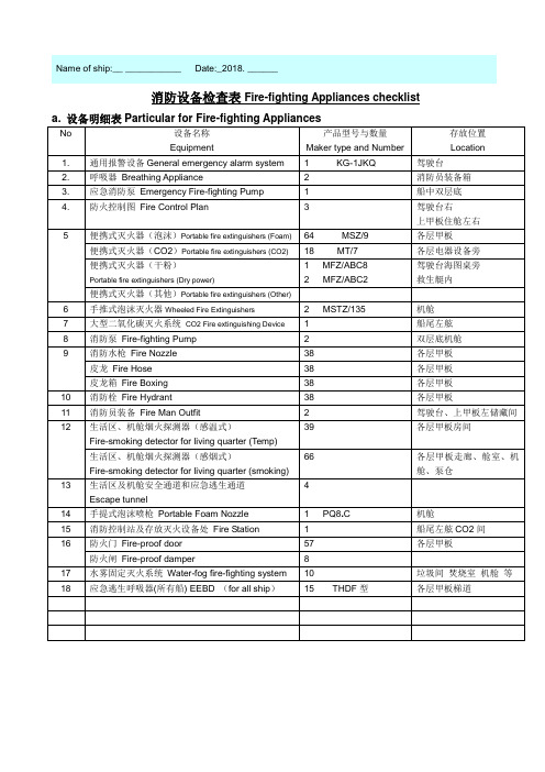
Equipment Checklist
- 格式:xls
- 大小:18.50 KB
- 文档页数:2
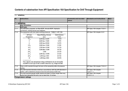
No.InstructionsComments and recordedvaluesStandards and instructionsRig'sRam Preventers Drift tests7.1.1The drift test is required on Ram BOP, Annular BOP, Hydraulic connectors, drilling spools and adapters.API Spec 16A chapter 7.5.8.47.1.2The equipment size and rated working pressure: TABLE 1-API 16AAPI Spec 16A chapter 4.2.27.1.3Pass a drift mandrel through the bore of the assembly after all pressure testingAPI Spec 16A chapter 7.5.8.4.17.1.4The drift mandrel diameter shall be in accordance with the drift diameter in Table 1 with a tolerance of plus 0.010 inch and minus 0.000 inchAPI Spec 16A chapter 7.5.8.4.1.17.1.5The drift mandrel gauge length shall be at least 2 inches longer than any cavity that intersects the bore, but no less than 12 inches.API Spec 16A chapter 7.5.8.4.1.2Temperature ratings7.1 GENERALContents of substraction from API Specification 16A Specification for Drill Through Equipment7.1 GENERALvaluesAPI Spec 16A chapter 4.2.2 7.1.6The minimum temperature is the lowest ambient temperature theequipment may be subjected.API Spec 16A chapter 4.2.2 7.1.7The maximum temperature is the highest temperature of the fluid whichmay flow through the equipmentAPI Spec 16A chapter 4.2.2.1 7.1.8Equipment shall be designed for metallic parts to operate with thetemperature shown in Table 2API Spec 16A chapter 8.3.4.2 7.1.9The temperature class of the welfare non metallic components shall be asfollows:7.1.10Temperature Rating Metallic Materials API Spec 16A chapter 8.4.2.4values7.1.11Dimensions for the type 16B integral hubs shall be conform to table 5 of page 10 API Spec 16AAPI Spec 16A chapter 4.3.4.2.2.2.17.1.12Dimensions for the type 16B hubs blind hubs shall be conform Figure 3page 9 API Spec 16AAPI Spec 16A chapter 4.3.4.2.2.2.17.1.13Dimensions for the type 16BX integral hubs shall be conform to table 6.7 or 8 of API Spec 16AAPI Spec 16A chapter 4.3.4.2.3.2.17.1.14Dimensions for the type 16BX blind l hubs shall be conform to fig 3 of API Spec 16AAPI Spec 16A chapter 4.3.4.2.3.2.17.1.15Dimensions for all ring groves shall conform to Tables 6,7, or 8 of API Spec 16AAPI Spec 16A chapter 4.3.4.2.3.2.17.1.16Type BX hubs may be manufactured with corrosion resistant overlays in the ring grooves. Prior to overlay the ring grooves shall conform to API Specification 6AAPI Spec 16A chapter 4.3.4.2.3.47.1.17All clamps shall have grooves in their bores with 25 (+/-0.25) degree angles to fit API 16B and 16BX hubsAPI Spec 16A chapter 4.3.5.2.3.37.1.18All 25 degree surfaces in clamp grooves shall have a surface finish of 32RMS or lessAPI Spec 16A chapter 4.3.5.2.3.47.1.19The clamp bore shall provide a minimum of 0.125 inch radial clearance around the hub neck in the made up condition on all hubs it is designed to fitAPI Spec 16A chapter 4.3.5.2.3.67.1.20Spherical face heavy nuts or spherical washers shall be used to minimize potential bending in bolts.API Spec 16A chapter 4.3.5.2.3.87.1.21Type R, RX and BX ring-joint gaskets are used in flanged, studded and hub connections. Type R and RX gaskets are interchangeable in type R ring grooves. Only type RX gaskets are to be used with SR ring grooves. Only type BX gaskets are to be used with 6BX grooves. Type RX and BX gaskets are not interchangeable.API Spec 16A chapter 4.3.7.17.1.22Hydrostatic proof testing shall be as shown in Table 18 of API Spec 16A API Spec 16A chapter 7.5.8.6.2.2.7.1.22Table 18 - Hydrostatic Test Pressure (psi)API Spec 16A chapter 7.5.8.6.3.1ClampsUse of gasketsHydrostatic Proof Testing16B hubs16BX hubsvalues7.1.23The hydrostatic proof test shall consist of three steps:API Spec 16A chapter 7.5.8.6.4a) the initial pressure-holding period of not less than 3 minutes.b) the reduction of the pressure to zeroc) The second pressure-holding period of not less than 15 minutes7.1.24The timing of the test shall not start until the test pressure has beenstabilized within the manufacturer's specified range and the externalsurfaces have been thoroughly dried.API Spec 16A chapter 7.5.8.6.4.17.1.25The hydraulic operating chamber shall be tested at a minimum testpressure equal to 1.5 times the operating chambers rated workingpressure.API Spec 16A chapter 7.5.8.6.3.27.1.26Each ram and annular blow out preventer shall be subjected to a closedpreventer test after the hydraulic proof test. The hydraulic operating systempressure used shall be equal to or less than the manufacturer's specifiedoperating pressure.API Spec 16A chapter 7.5.8.7.1.17.1.27The timing of all closed preventer tests shall not start until the test pressurehas stabilised .API Spec 16A chapter 7.5.8.7.1.27.1.28Closed preventer tests shall be performed at low and high pressure with thelow pressure tests always preceding the high pressure test API Spec 16A chapter 7.5.8.7.1.37.1.29 A pressure of 200 to 300 psi shall be applied and held below the closedram or annular packing unit for a time period of not less than 10 minutesafter stabilization API Spec 16A chapter 7.5.8.7.1.3.1Hydraulic Operating Chamber Test Closed Preventer Testvaluesvaluesvaluesvaluesvalues。
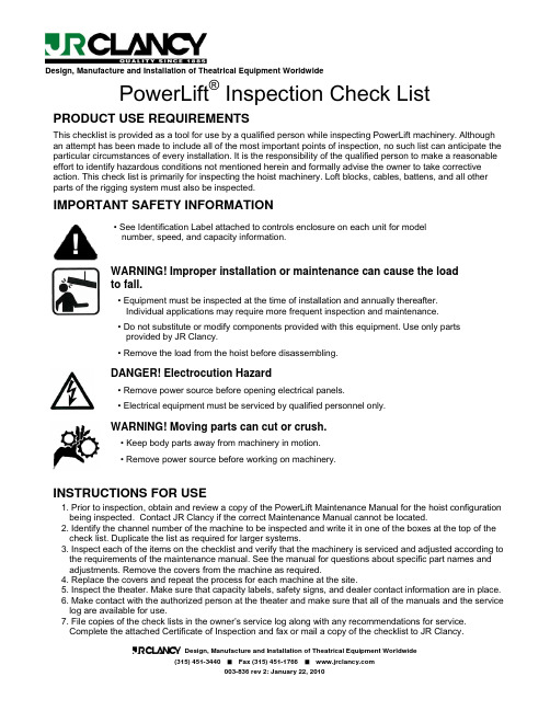
Design, Manufacture and Installation of Theatrical Equipment WorldwidePowerLift ®Inspection Check ListPRODUCT USE REQUIREMENTSThis checklist is provided as a tool for use by a qualified person while inspecting PowerLift machinery. Although an attempt has been made to include all of the most important points of inspection, no such list can anticipate the particular circumstances of every installation. It is the responsibility of the qualified person to make a reasonable effort to identify hazardous conditions not mentioned herein and formally advise the owner to take corrective action. This check list is primarily for inspecting the hoist machinery. Loft blocks, cables, battens, and all other parts of the rigging system must also be inspected.IMPORTANT SAFETY INFORMATION• See Identification Label attached to controls enclosure on each unit for model number, speed, and capacity information.WARNING! Improper installation or maintenance can cause the load to fall.• Equipment must be inspected at the time of installation and annually thereafter. Individual applications may require more frequent inspection and maintenance. • Do not substitute or modify components provided with this equipment. Use only parts provided by JR Clancy.• Remove the load from the hoist before disassembling.DANGER! Electrocution Hazard• Remove power source before opening electrical panels.• Electrical equipment must be serviced by qualified personnel only.WARNING! Moving parts can cut or crush.• Keep body parts away from machinery in motion. • Remove power source before working on machinery.INSTRUCTIONS FOR USE1. Prior to inspection, obtain and review a copy of the PowerLift Maintenance Manual for the hoist configuration being inspected. Contact JR Clancy if the correct Maintenance Manual cannot be located.2. Identify the channel number of the machine to be inspected and write it in one of the boxes at the top of the check list. Duplicate the list as required for larger systems.3. Inspect each of the items on the checklist and verify that the machinery is serviced and adjusted according to the requirements of the maintenance manual. See the manual for questions about specific part names and adjustments. Remove the covers from the machine as required.4. Replace the covers and repeat the process for each machine at the site.5. Inspect the theater. Make sure that capacity labels, safety signs, and dealer contact information are in place.6. Make contact with the authorized person at the theater and make sure that all of the manuals and the service log are available for use.7. File copies of the check lists in the owner’s service log along with any recommendations for service. Complete the attached Certificate of Inspection and fax or mail a copy of the checklist to JR Clancy.PowerLift Inspection ChecklistVenue Name:_____________________________________Date of Inspection : _______________________Channel NumbersCheck machine covers Machines with moving parts within 106 inches (2.7m) vertically from the floor and less than 60 inches (1.5m) horizontally from a safety barrier must be fitted with machine covers. Otherwise covers may be omitted at the discretion of the customer.Roll pins are in place at each end of beam.Beam flanges where the machine is attached are less than 8” (20 cm) wide and less than 1” (2.5cm) thick. Flanges are at least 4” (10 cm) wide and 1/4" (6 mm) thick.Check mounting clampsClamp rods are tightened. Thrust plates installed on both ends of hoist. Jam nuts are installed and tightened.Sheave fleet angles are within 1.5 degrees. Cables do not rub side plates of head or loft blocks. Cables are not twisted.Only one line wraps more than 20 degrees around the sheave of the beam mounted loft blocks(if provided). That line is in the 3rdgroove as marked.The drum/head block fleet angle matches the helix angle of the drum. Checkblocks and reevingWire rope is free of kinks, corrosion, distortion, and broken strands.Cable keeper roller installation matches the directions in the Maintenance ManualExposed parts of drive shaft are clean and lubricated. Drum screw is clean and lubricated. Rubber protective band has been removed from the reducer breather valveFor electric load brake, the manual release bolts of the secondary load brake have beenremoved. The gap between the load brake magnet and armature measures 0.9 mm (0.035”) For mechanical Weston Brake, the bottom of the dust groove in the brake pads is visible on all pads of the brake. The disks of the Weston Brake are free from dirt and oil.Check machineryThe mounting position on the gear reducer name plate matches the actual mounting position of the PowerLift. No apparent oil leaks. Oil level is correct for the mounting position. Replace or lab test gearbox oil every two years.Control enclosure covers are in place. No missing fasteners Strain relief connections are tight.Power plugs are twist-locked into receptacles. Control plugs are latched into receptacles. Check electricalUnused control plugs are closed and latchedLimit switch brackets and activation arms are in good condition and not bentHard limits are set and checked. For electric load brake, 6“ (15 cm) from any obstruction. For mechanical Weston Brake, 6” (15 cm) for fixed speed units, 14” (36 cm) for variable speed units. With the machine on down hard limit there are at least three dead wraps on drum for each line Machine runs smoothly throughout entire range of travel Limit switch locking nuts are tightenedFor electric load brake, when hoist stops after lifting batten, motor brake engages before load brake engages. When the hoist is moving the batten, the load brake is open and does not rub Check operation and limit switchesFor mechanical Weston Brake, when hoist is lifting batten, motor brake stops the load before the load brake pawls engage. When the hoist is lowering batten, the load brake engages consistentlyCapacity labels are in place on each batten and match the machine capacity on the hoist Identification LabelMotorized rigging safety sign is installed and dealer contact information has been filled in Jumper has been removed from service light timer. Timer is reset and light is off.Check the availability of safety information materialsOwner has copies of the Installation, Operation, and Maintenance Manuals, and Service Log.Design, Manufacture and Installation of Theatrical Equipment Worldwide J.R. Clancy, Incorporated7041 Interstate Island Road Syracuse, New York USA 13209-9713 Telephone: (315) 451-3440 Facsimile: (315) 451-1766ISO 9001 CertifiedCertificate of InspectionI have inspected each of the PowerLift machines in this facility and I have verified that the machinery is configured and maintained according to the Maintenance Manual.Is this a new installation or periodic inspection? ___________________________Name of venue: ______________________________________City and State: ______________________________________Date of Inspection: ______________________________________Name of Inspector (print): ______________________________________Company of Inspector: ______________________________________Signature of Inspector: _______________________Date___________Attach checklist for all PowerLift machines to this form and submit to JR Clancy in order to preserve the full duration of the original factory warranty as specified in the owner’s Operations Manual.Place copies of the checklists and this certificate into the owner’s Maintenance and InspectionLog each time the system is inspected.。

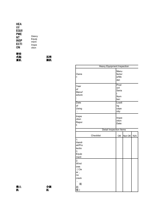
移动式起重机压挖掘机
推土机分级机
降机转臂起重机压路机
C混凝土切割机/盘形夯土机检查混凝土切割机M/C
盘形夯土机 M/C
夯土机
空气压缩机检查
发电机检查
场分布面板检查
临时接线电缆检查
焊接机检查
电动钻孔机/转矩扳手检查
电机炉检查
气割设备检查
背带检查
铰链辘检查
钢绳吊带检查
尼龙网吊带检查
聚酯环形吊带检查
挂钩检查
升降台与转臂升降机工作安全使用指导
升降台
起重臂升降机
移动型脚手架安全使用指导
在站点上进行燃料补充的安全操作指导
临时危险性材料存放检查。