
MX1H系列可编程控制器硬件手册[1]
- 格式:pdf
- 大小:3.60 MB
- 文档页数:2
![MX1H系列可编程控制器硬件手册[1]](https://imgs-1438308264.cos.ap-hongkong.myqcloud.com/4644c601763231126edb1196.webp)

Agilent H SMx-C120/C177/C197/C265High Performance Chip LEDsData SheetFeatures•High brightness AlInGaP material •0805 or 0603 industry standard footprint with 0.4 mm height for top emitting packages•Also available in right angle emitting and reverse mounting packages•Diffused optics•Operating temperature range of –30°C to +85°C•Compatible with IR soldering •Available in 4 colors•Available in 8 mm tape on 7"diameter reel•Reel sealed in zip locked moisture barrier bags Applications•Membrane switch indicator •LCD backlighting•Push button backlighting •Front panel indicator •Symbol backlighting •Keypad backlighting •Microdisplays•Small message panel signageDescriptionThese chip type LEDs utilize Aluminium Indium Galium Phosphide (AlInGaP) material technology. The AlInGaP material has a very high luminousefficiency, capable of producing high light output over a wide range of drive currents. The available colors in this surface mount series are 592 nm Amber,605 nm Orange, 626 nm Red and 639 nm Deep Red.All packages are binned by both color and intensity, except for red and deep red color.These ChipLEDs come either in low profile top emitting packages (HSMx-C177/C197), in a sideemitting package (HSMx-C120)or in a reverse mount package (HSMx-C265). The right angle ChipLED is suitable for applica-tions such as LCD back lighting.The top emitting ChipLEDs with wide viewing angle are suitable for light piping and direct back-lighting of keypads and panels.The reverse mount ChipLED is suitable for space saving.In order to facilitate pick and place operation, these ChipLEDs are shipped in tape and reel, with 4000 units per reel for HSMx-C120/C177/C197 and 3000 units per reel for HSMx-C265.These packages are compatible with IR soldering process.Device Selection GuideDimensions (mm)[1,2]Amber RedOrange Deep Red Package Description 1.6 x 0.6 x 1.0HSMA-C120HSMC-C120HSML-C120–Untinted, Non-diffused 2.0 x 1.25 x 0.4HSMA-C177HSMC-C177HSML-C177HSMT-C177Untinted, Diffused 1.6 x 0.8 x 0.4HSMA-C197HSMC-C197HSML-C197HSMT-C197Untinted, Diffused 3.4 x 1.25 x 1.1HSMA-C265HSMC-C265HSML-C265HSMT-C265Untinted, Non-diffusedPackage DimensionsPOLARITYTERMINAL0.40 ± 0.15HSMx-C177POLARITY0.30 ± 0.15TERMINALHSMx-C1970.50 ± 0.15POLARITY0.50 ± 0.15TERMINALHSMx-C265POLARITYTERMINALHSMx-C120NOTES:1. ALL DIMENSIONS IN MILLIMETERS (INCHES).2. TOLERANCE IS ± 0.1 mm (± 0.004 IN.) UNLESS OTHERWISE SPECIFIED.Absolute Maximum Ratings at T A = 25˚CParameter HSMx-Cxxx UnitsDC Forward Current [1]25mAPeak Pulsing Current[2]100mAPower Dissipation60mWReverse Voltage (I R = 100 µA)5VLED Junction Temperature95˚COperating Temperature Range–30 to +85˚CStorage Temperature Range–40 to +85˚CSoldering Temperature See reflow soldering profile (Figures 8 & 9)Notes:1. Derate linearly as shown in Figure 4.2. Pulse condition of 1/10 duty and 0.1 ms width.Electrical Characteristics at T A = 25˚CForward Voltage Reverse Breakdown Capacitance C ThermalV F (Volts)V R (Volts)(pF), V F = 0,Resistance@ I F = 20 mA@ I R = 100 µA f = 1 MHz RθJ–PIN(˚C/W) Part Number Typ.Max.Min.Typ.Typ.HSMA-C120 1.9 2.4511400HSMA-C177/197 1.9 2.4511300HSMA-C265 1.9 2.4511550HSMC-C120 1.9 2.4515400HSMC-C177/197 1.9 2.4515300HSMC-C265 1.9 2.4515550HSML-C120 1.9 2.4520400HSML-C177/197 1.9 2.4520300HSML-C265 1.9 2.4520550HSMT-C177/197 1.9 2.4515300HSMT-C265 1.9 2.4515550V F Tolerance: ± 0.1 VOptical Characteristics at T A = 25˚CLuminous Color,Viewing LuminousIntensity Peak Dominant Angle EfficacyI V (mcd)Wavelength Wavelength 2 θ1/2ηV@ 20 mA[1]λpeak (nm)λd[2](nm)Degrees[3](lm/w) Part Number Color Min.Typ.Typ.Typ.Typ.Typ. HSMA-C120Amber28.590595592155480 HSMA-C177/197Amber28.590595592130480 HSMA-C265Amber28.575595592150480 HSMC-C120Red28.590637626155155 HSMC-C177/197Red28.590637626130155 HSMC-C265Red28.575637626150155HSML-C120Orange28.590609605155370HSML-C177/197Orange28.590609605130370HSML-C265Orange28.575609605150370 HSMT-C177/197Deep Red11.23066063913070HSMT-C265Deep Red11.22566063915070Notes:1.The luminous intensity, I V, is measured at the peak of the spatial radiation pattern which may not be aligned with the mechanical axis of the lamp package.2.The dominant wavelength, λd, is derived from the CIE Chromaticity Diagram and represents the perceived color of the device.3.θ1/2 is the off-axis angle where the luminous intensity is 1/2 the peak intensity.Light Intensity (Iv) Bin Limits [1]Intensity (mcd)Bin ID Min.Max.A 0.110.18B 0.180.29C 0.290.45D 0.450.72E 0.72 1.10F 1.10 1.80G 1.80 2.80H 2.80 4.50J 4.507.20K 7.2011.20L 11.2018.00M 18.0028.50N 28.5045.00P 45.0071.50Q 71.50112.50R 112.50180.00S 180.00285.00T 285.00450.00U 450.00715.00V 715.001125.00W 1125.001800.00X 1800.002850.00Y 2850.004500.00Note:1.Bin categories are established for classifica-tion of products. Products may not be avail-able in all categories. Please contact your Agilent representative for information on currently available bins.Amber Color Bins [1]Dom. Wavelength (nm)Bin ID Min.Max.A 582.0584.5B 584.5587.0C 587.0589.5D 589.5592.0E 592.0594.5F594.5597.0Orange Color Bins [1]Dom. Wavelength (nm)Bin ID Min.Max.A 597.0600.0B 600.0603.0C 603.0606.0D 606.0609.0E 609.0612.0F612.0615.0Tolerance: ± 0.5 nmNote:1. Bin categories are established for classification of products. Products may not be available in all categories. Please contact your Agilent representative for information on currently available bins.Tolerance: ± 1 nmTolerance: ± 15%Color Bin LimitsFigure 4. Maximum forward current vs.ambient temperature.Figure 3. Luminous intensity vs. forward current.I F – FORWARD CURRENT – mA00.41.0L U M I N O U S I N T E N S I T Y (N O R M A L I Z E D A T 20 m A )0.60.20.81.41.2Figure 2. Forward current vs. forward voltage.Figure 1. Relative intensity vs. wavelength.WAVELENGTH – nmR E L A T I V E I N T E N S I T Y – %500550600650700100101V F – FORWARD VOLTAGE – VI F – F O R W A R D C U R R E N T – m AI F M A X – M A X I M U M F O R W A R D C U R R E N T – m AT A – AMBIENT TEMPERATURE – °CFigure 5. Relative intensity vs. angle for HSMx-C120.100908070605040302010R E L A T I V E I N T E N S I T Y-90-80-70-60-50-40-30-20-100102030405060708090ANGLE100908070605040302010R E L A T I V E I N T E N S I T Y-90-80-70-60-50-40-30-20-100102030405060708090ANGLEFigure 6. Relative intensity vs. angle for HSMx-C177/197.Figure 9. Recommended Pb-free reflow soldering profile.Figure 10. Recommended soldering pattern for HSMx-C177.R E L A T I V E I N T E N S I T Y – %1000ANGLE806050702010304090-70-50-3002030507090-90-20-80-60-40-1010406080(0.035)0.8 (0.028)BOARDFigure 11. Recommended soldering pattern for HSMx-C197.Figure 7. Relative intensity vs. angle for HSMx-C265.R E L A T I V E I N T E N S I T Y – %1000ANGLE806050702010304090-70-50-3002030507090-90-20-80-60-40-1010406080NOTE:1. ALL DIMENSIONS IN MILLIMETERS (INCHES).TIMET E M P E R A T U R E* THE TIME FROM 25 °C TO PEAK TEMPERATURE = 6 MINUTES MAX.Figure 8. Recommended reflow soldering profile.T E M P E R A T U R EFigure 14. Reeling orientation.Figure 15. Reel dimensions.Figure 12. Recommended soldering pattern for HSMx-C120.Figure 13. Recommended soldering pattern for HSMx-C265.(0.031)(0.031)(0.047)Ø 20.20 MIN. (Ø 0.795 MIN.)Ø 13.1 ± 0.5 NOTE:1. ALL DIMENSIONS IN MILLIMETERS (INCHES).Figure 16. Tape dimensions.TABLE 1DIMENSIONS IN MILLIMETERS (INCHES)DIM. A ± 0.10 (0.004)DIM. B ± 0.10 (0.004)PART NUMBER DIM. C ± 0.10 (0.004)HSMx-C120 SERIES HSMx-C177 SERIES HSMx-C197 SERIES(0.020 ± 0.002)0.80 (0.031) 0.60 (0.024) 0.60 (0.024)1.90 (0.075)2.30 (0.091) 1.80 (0.071) 1.15 (0.045) 1.40 (0.055) 0.95 (0.037)NOTES:1. ALL DIMENSIONS IN MILLIMETERS (INCHES).2. TOLERANCE IS ± 0.1 mm (± 0.004 IN.) UNLESS OTHERWISE SPECIFIED.HSMx-C265 SERIES 3.70 (0.146) 1.45 (0.057) 1.30 (0.051)TABLE 1DIMENSIONS IN MILLIMETERS (INCHES)DIM. A ± 0.10 (0.004)DIM. B ± 0.10 (0.004)PART NUMBERDIM. C ± 0.10 (0.004)/semiconductorsFor product information and a complete list of distributors, please go to our web site.For technical assistance call:Americas/Canada: +1 (800) 235-0312 or (916) 788-6763Europe: +49 (0) 6441 92460China: 10800 650 0017Hong Kong: (+65) 6756 2394India, Australia, New Zealand: (+65) 6755 1939Japan: (+81 3) 3335-8152(Domestic/Interna-tional), or 0120-61-1280(Domestic Only)Korea: (+65) 6755 1989Singapore, Malaysia, Vietnam, Thailand,Philippines, Indonesia: (+65) 6755 2044Taiwan: (+65) 6755 1843Data subject to change.Copyright © 2004 Agilent Technologies, Inc.Obsoletes 5988-5501EN April 22, 20045989-0551ENConvective IR Reflow Soldering For more information on IR reflow soldering, refer toApplication Note 1060, Surface Mounting SMT LED Indicator Components .Storage Condition:5 to 30°C @ 60% RH max.Baking is required under the condition:a) the blue silica gel indicator becoming white/transparent colorb) the pack has been open for more than 1 weekBaking recommended condition:60 ± 5°C for 20 hours.Figure 17. Tape leader and trailer dimensions.END STARTSEALED WITH COVER TAPE.SEALED WITH COVER TAPE.OF CARRIER AND/ORCOVER TAPE.。
6100系列视频服务器用户使用手册(Ver2.0)非常感谢您购买我公司的产品,如果您有什么疑问或需要请随时联系我们。
本手册适用于DS-6100HC、DS-6100HF视频服务器。
本手册可能包含技术上不准确的地方、或与产品功能及操作不相符的地方、或印刷错误。
本手册的内容将根据产品功能的增强而更新,并将定期改进或更新本手册中描述的产品或程序,更新的内容将会在本手册的新版本中加入,恕不另行通知。
物 品 清 单小心打开包装盒,检查包装盒里面应有以下配件:¾一台视频服务器¾一本用户手册¾一根DTE线¾一根电源线¾一张保修卡¾一张合格证¾一个光盘如果发现有所损坏或者任何配件短缺的情况,请及时和经销商联系。
第一章用户手册简介感谢您购买DS-6100系列视频服务器!在您准备使用本产品之前,请先仔细阅读本手册,以便能更好的使用本产品的所有功能。
1.1用途本手册的用途是帮助您熟悉和正确的使用DS-6100系列视频服务器!1.2用户手册概述第一章:用户手册简介第二章:产品概述第三章:硬件安装第四章:软件安装第五章:参数配置第六章:广域网接入附录A:常见问题解答附录B:技术参数第二章产品概述2.1产品简介DS-6100系列视频服务器是专为远程监控而设计的嵌入式数字监控产品,采用最新的达芬奇平台处理芯片,LINUX嵌入式系统,完全脱离PC 平台,系统调度效率高,代码固化在FLASH中,系统运行更加稳定可靠。
DS-6100系列视频服务器具有视频信号和音频信号的硬件同步压缩功能,压缩码流通过网络进行传输,通过网络可进行实时视频和音频预览,支持流协议(RTP/RTCP),支持IE预览,支持双向语音对讲,多种语言支持等功能。
2.2 产品型号说明根据编码分辨率分两种:¾DS-6100HC:1~4路视频,音频输入,每路的视频分辨率最高支持CIF,也可以选择QCIF,不可以安装硬盘。

October 2012MX239HLCD MonitorUser GuideiiCopyright © 2012 ASUSTeK COMPUTER INC. All Rights Reserved.No part of this manual, including the products and software described in it, may be reproduced, transmitted, transcribed, stored in a retrieval system, or translated into any language in any form or by any means, except documentation kept by the purchaser for backup purposes, without the express written permission of ASUSTeK COMPUTER INC. (“ASUS”).Product warranty or service will not be extended if: (1) the product is repaired, modified or altered, unless such repair, modification of alteration is authorized in writing by ASUS; or (2) the serial number of the product is defaced or missing.ASUS PROVIDES THIS MANUAL “AS IS” WITHOUT WARRANTY OF ANY KIND, EITHER EXPRESS OR IMPLIED, INCLUDING BUT NOT LIMITED TO THE IMPLIED WARRANTIES OR CONDITIONS OF MERCHANTABILITY OR FITNESS FOR A PARTICULAR PURPOSE. IN NO EVENT SHALL ASUS, ITS DIRECTORS, OFFICERS, EMPLOYEES OR AGENTS BE LIABLE FOR ANY INDIRECT, SPECIAL, INCIDENTAL, OR CONSEQUENTIAL DAMAGES (INCLUDING DAMAGES FOR LOSS OF PROFITS, LOSS OF BUSINESS, LOSS OF USE OR DATA, INTERRUPTION OF BUSINESS AND THE LIKE), EVEN IF ASUS HAS BEEN ADVISED OF THE POSSIBILITY OF SUCH DAMAGES ARISING FROM ANY DEFECT OR ERROR IN THIS MANUAL OR PRODUCT.SPECIFICATIONS AND INFORMATION CONTAINED IN THIS MANUAL ARE FURNISHED FOR INFORMATIONAL USE ONLY, AND ARE SUBJECT TO CHANGE AT ANY TIME WITHOUT NOTICE, AND SHOULD NOT BE CONSTRUED AS A COMMITMENT BY ASUS. ASUS ASSUMES NO RESPONSIBILITY OR LIABILITY FOR ANY ERRORS OR INACCURACIES THAT MAY APPEAR IN THIS MANUAL, INCLUDING THE PRODUCTS AND SOFTWARE DESCRIBED IN IT.Products and corporate names appearing in this manual may or may not be registered trademarks or copyrights of their respective companies, and are used only for identification or explanation and to the owners’ benefit, without intent to infringe.Table of contentsNotices..........................................................................................................iii rmation.......................................................................................iv Care.&.Cleaning.. (v)1.1.Welcome!.......................................................................................1-11.2.Package.contents..........................................................................1-11.3.Monitor.introduction.....................................................................1-21.3.1 Front of the LCD monitor ................................................1-21.3.2 Rear of the LCD monitor .................................................1-41.3.3 QuickFit Function ............................................................1-52.1.Assembling.the.base....................................................................2-12.2.Connecting.cables........................................................................2-12.3.Detaching.the.base.......................................................................2-22.4.Adjusting.the.monitor...................................................................2-33.1.OSD.(On-Screen.Display).menu..................................................3-13.1.1 How to reconfigure ..........................................................3-13.1.2 OSD Function Introduction ..............................................3-13.2.Specifications................................................................................3-63.3.Troubleshooting.(FAQ).................................................................3-73.4.Supported.Timing.List..................................................................3-8Noticesmission.StatementThis device complies with Part 15 of the FCC Rules. Operation is subjectto the following two conditions:• This device may not cause harmful interference, and• This device must accept any interference received including interference that may cause undesired operation.This equipment has been tested and found to comply with the limits for a Class B digital device, pursuant to Part 15 of the FCC Rules. These limitsare designed to provide reasonable protection against harmful interferencein a residential installation. This equipment generates, uses and canradiate radio frequency energy and, if not installed and used in accordance with manufacturer’s instructions, may cause harmful interference to radio communications. However, there is no guarantee that interference willnot occur in a particular installation. If this equipment does cause harmful interference to radio or television reception, which can be determined by turning the equipment off and on, the user is encouraged to try to correctthe interference by one or more of the following measures:• Reorient or relocate the receiving antenna.• Increase the separation between the equipment and receiver.• Connect the equipment to an outlet on a circuit different from that to which the receiver is connected.• Consult the dealer or an experienced radio/TV technician for help. munications.StatementThis digital apparatus does not exceed the Class B limits for radionoise emissions from digital apparatus set out in the Radio Interference Regulations of the Canadian Department of Communications.This class B digital apparatus complies with Canadian ICES-003.iiiivSafety information• Before setting up the monitor, carefully read all the documentation that came with the package.• To prevent fire or shock hazard, never expose the monitor to rain or moisture.• Never try to open the monitor cabinet. The dangerous high voltages inside the monitor may result in serious physical injury.• If the power supply is broken, do not try to fix it by yourself. Contact a qualified service technician or your retailer.• Before using the product, make sure all cables are correctly connected and the power cables are not damaged. If you detect any damage, contact your dealer immediately.• Slots and openings on the back or top of the cabinet are provided for ventilation. Do not block these slots. Never place this product near or over a radiator or heat source unless proper ventilation is provided.• The monitor should be operated only from the type of power source indicated on the label. If you are not sure of the type of power supply to your home, consult your dealer or local power company.• Use the appropriate power plug which complies with your local power standard.• Do not overload power strips and extension cords. Overloading can result in fire or electric shock.• Avoid dust, humidity, and temperature extremes. Do not place the monitor in any area where it may become wet. Place the monitor on a stable surface.• Unplug the unit during a lightning storm or if it will not be used for a long period of time. This will protect the monitor from damage due to power surges.• Never push objects or spill liquid of any kind into the slots on the monitor cabinet.• To ensure satisfactory operation, use the monitor only with UL listed computers which have appropriate configured receptacles marked between 100 ~ 240V AC.• The socket-outlet shall be installed near the equipment and shall be easily accessible• If you encounter technical problems with the monitor, contact a qualified service technician or your retailer.Use only the AC/DC adapter model: AD 3 *' %&(;$ <+vCare & Cleaning• Before you lift or reposition your monitor, it is better to disconnect the cables and power cord. Follow the correct lifting techniques when positioning the monitor. When lifting or carrying the monitor, grasp the edges of the monitor. Do not lift the display by the stand or the cord.• Cleaning. Turn your monitor off and unplug the power cord. Clean the monitor surface with a lint-free, non-abrasive cloth. Stubborn stains may be removed with a cloth dampened with mild cleaner.• Avoid using a cleaner containing alcohol or acetone. Use a cleaner intended for use with the LCD. Never spray cleaner directly on the screen, as it may drip inside the monitor and cause an electric shock.The.following.symptoms.are.normal.with.the.monitor:• The screen may flicker during the initial use due to the nature of the fluorescent light. Turn off the Power Switch and turn it on again to make sure that the flicker disappears.• You may find slightly uneven brightness on the screen depending on the desktop pattern you use.• When the same image is displayed for hours, an afterimage of the previous screen may remain after switching the image. The screen will recover slowly or you can turn off the Power Switch for hours.• When the screen becomes black or flashes, or cannot work anymore, contact your dealer or service center to fix it. Do not repair the screen by yourself!ed.in.this.guideWARNING: Information to prevent injury to yourself when trying tocomplete a task.CAUTION: Information to prevent damage to the componentswhen trying to complete a task.IMPORTANT: Information that you MUST follow to complete atask.NOTE: Tips and additional information to aid in completing a task.rmationRefer to the following sources for additional information and for productand software updates.1..ASUS.websitesThe ASUS websites worldwide provide updated information on ASUShardware and software products. Refer to 2..Optional.documentationYour product package may include optional documentation that mayhave been added by your dealer. These documents are not part ofthe standard package.vi1-1ASUS LCD Monitor MX239H 1.1.Welcome!Thank you for purchasing the ASUS ® LCD monitor!The latest widescreen LCD monitor from ASUS provides a crisper, broader, and brighter display, plus a host of features that enhance your viewing experience.With these features, you can enjoy the convenience and delightful visual experience that the monitor brings you!1.2.Package.contentsCheck your package for the following items:LCD MonitorMonitor BaseQuick Start GuideWarranty Card1x Power Cord1x Power Adapter1x VGA Cable1x HDMI-DVI Cable1x Audio Cable• If any of the above items is damaged or missing, contact your retailerimmediately.1. QuickFit Button:• This is a hotkey to activate the QuickFit function designed for alignment.• The QuickFit function contains 7 pages of common grid patterns, paper sizes, and photo sizes. See page 1-5 for details.2. Button:• Automatically adjust the image to its optimized position, clock, and phase by long pressing this button for 2-4 seconds (for VGA mode only).• Use this hotkey to switch from six video preset modes (Scenery,Standard, Theater, Game, Night View, and sRGB Mode) withSPLENDID™ Video Intelligence Technology.• Exit the OSD menu or go back to the previous menu as the OSD menu is active.3. Button:• Press this button to decrease the value of the function selected or move to the next function.• This is also a hotkey for Volume adjustment.4. MENU Button:• Press this button to enter the OSD menu.• Press this button to enter/select the icon (function) highlighted while the OSD is activated.1-2Chapter 1: Product Introduction5. Button:• Press this button to increase the value of the function selected or move to the previous functions.• This is also a hotkey for Brightness adjustment.6.7.• Press this button to turn the monitor on/off.• The color definition of the power indicator is as the below table.ASUS LCD Monitor MX239H1-31.3.2.Rear.of.the.LCD.monitor1. DC-in Port2. HDMI Port3. VGA Port4. Audio-in Port5. Earphone-out Port6. Kensington Lock7. Control Buttons1-4Chapter 1: Product Introduction1-5ASUS LCD Monitor MX239H1.3.3.QuickFit.FunctionThe QuickFit function contains three patterns: (1) Grid (2) Paper size (3) Photo size.1.Grid pattern: Facilitates designers and users to organize content and layout on one page and achieve a consistent look and feel.2.Paper size: Provides users to view their documents in real size on the screen.3.Photo size: Provides photographers and other users to accurately view and edit their photos in real size on the screen.2.1.Assembling.the.baseTo assemble the base:1. Carefully put the front of the monitor face down on a clean table.2. Attach the base to the stand. Use your fingers to screw the base tothe stand tightly.3. The monitor is now ready for connection.• We recommend that you cover the table surface with soft cloth to preventdamage to the monitor.2.2.Connecting.cablesConnect the cables you need based on the introductions on chapter 1.3.2,page 1-4.2-1Chapter 2: Setup2-2ASUS LCD Monitor MX239H 2.3.Detaching.the.baseTo detach the base:1. Disconnect power and signal cables. Carefully put the front of the monitor face down on a clean table.2. Use your fingers to loosen the screw located at the bottom of the base, and remove the base from the stand.3.Or you may directly use a screwdriver to remove the screw thatsecure the base to the stand, and detach the base from the stand.• We recommend that you cover the table surface with soft cloth to prevent damage to the monitor.•Hold the base while removing the screw.2-3Chapter 2: Setup2.4.Adjusting.the.monitor• For optimal viewing, we recommend that you look at the full face of themonitor, then adjust the monitor to the angle that is most comfortable for you.• Hold the stand to prevent the monitor from falling while changing itsangle.•You can adjust the monitor’s angle from -5˚ to 20˚.-5 ~ 203.1.OSD.(On-Screen.Display).menu3.1.1.How.to.reconfigure1. Press the MENU button to activate the OSD menu.2. Press ❑ and ☐ to navigate through the functions. Highlight andactivate the desired function by pressing the MENU button. If thefunction selected has a sub-menu, press ❑ and ☐ again to navigatethrough the sub-menu functions. Highlight and activate the desiredsub-menu function by pressing the MENU button.3. Press ❑ and ☐ to change the settings of the selected function.4. To exit the OSD menu, press the button. Repeat step 2 andstep 3 to adjust any other function.3.1.2.OSD.Function.Introduction1..SplendidThis function contains six sub-functions that you can select for yourpreference. Each mode has the Reset selection, allowing you tomaintain your setting or return to the preset mode.•.Scenery.Mode: This is the best choice for scenery photo displaying with SPLENDID™ Video Intelligence Technology.ASUS LCD Monitor MX239H3-13-2Chapter 3: General Instruction•.Standard.Mode : This is the best choice for document editing with SPLENDID™ Video Intelligence Technology.•.Theater.Mode : This is the best choice for movie watching with SPLENDID™ Video Intelligence Technology.•.Game.Mode : This is the best choice for game playing with SPLENDID™ Video Intelligence Technology.•.Night.View.Mode : This is the best choice for playing dark-scene game or watching dark-scene movie with SPLENDID™ Video Intelligence Technology.•.sRGB.Mode : This is the best choice for viewing photos and graphicsfrom PCs.• In the Standard Mode, the Saturation, SkinTone, Sharpness, and ASCR functions are not user-configurable.•In the sRGB, the Saturation, Color Temp., SkinTone, Sharpness, Brightness, Contrast and ASCR functions are not user-configurable.2..ColorSelect the image color you like from this function.•.Brightness also a hotkey to activate this function.•.Contrast : The adjusting range is from 0 to 100.•.Saturation : The adjusting range is from 0 to 100.•.Color.Temp.: Contains three preset color modes (Cool , Normal , Warm ) and one User Mode.•.Skin.Tone : Contains three color modes including Reddish , Natural , and Yellowish .•.Smart.View : The versatile viewing positions with Smart View Technology.3-3ASUS LCD Monitor MX239H •In the User Mode, colors of R (Red), G (Green), and B (Blue) are user-configurable; the adjusting range is from 0 ~ 100..3..ImageYou can adjust the image Sharpness, Trace Free, Aspect Control, ASCR, Position (VGA only), and Focus (VGA only) from this main function.•.Sharpness : Adjusts the picture sharpness. The adjusting range is from 0 to 100.•.Trace.Free:.Speeds up the response time by Over Drive technology. The adjusting range is from lower 0 to faster 100.•.Aspect.Control : Adjusts the aspect ratio to “Full ”, “4:3”,“Overscan ”. •.ASCR : Select ON or OFF to enable or disable dynamic contrast ratio function.•.Position : Adjusts the horizontal position (H-Position ) and the vertical position (V-Position ) of the image. The adjusting range is from 0 to 100 (Only available for VGA input).•.Focus : Reduces Horizonal-line noise and Vertical-line noise of the image by adjusting (Phase ) and (Clock ) separately. The adjusting range is from 0 to 100 (Only available for VGA input).• •4..Input.SelectSelect the input source from VGA, HDMI1, or HDMI2.input signal.5..System.SetupAdjusts the system configuration.•.Splendid.Demo.Mode: Activate the demo mode for the Splendidfunction.•.Volume:.Adjust the earphone or speaker output volume level. The adjusting range is from 0 to 100.3-4Chapter 3: General Instruction•.ECO.Mode: Activate the ecology mode for power saving.•.OSD.Setup: Adjusts the horizontal postition (H-Position), verticalposition (V-Position), OSD.Timeout, DDC/CI, and Transparency of theOSD screen.•.Language: Select OSD language. The selections are: English, French, German, Spanish, Italian, Dutch, Russian, Traditional Chinese,Simplified Chinese, Japanese, Persian, Thai, Indonesian, Poland,Turkey, Portugal, Czech, Croatia, Hungary, Romania, and Korean.•.Information: Displays the monitor information.•.All.Reset: Selects “Yes” to revert all settings to the factory default mode.ASUS LCD Monitor MX239H3-53.2.Specifications3-6Chapter 3: General Instruction3.3.Troubleshooting.(FAQ)ASUS LCD Monitor MX239H3-73.4.Supported.Timing.ListVESA./.IBM.Modes.Support.Timing.(D-SUB,.HDMI.inputs)HDMI.1.3.CEA-861.Formats.Supported.Timing.(HDMI.input)*..T he.modes.not.listed.in.the.above.tables.may.not.be.supported..For.optimal.resolution,.we.recommend.that.you.choose.a.mode.listed.in.the.above.tables.3-8Chapter 3: General Instruction。
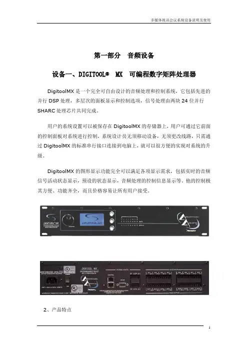
第一部分音频设备设备一、DIGITOOL®MX 可编程数字矩阵处理器DigitoolMX是一个完全可自由设计的音频处理和控制系统,它包括先进的并行DSP处理,多层次的面板显示和控制选项,信号处理由两块24位并行SHARC处理芯片共同完成。
用户的系统设置可以被保存在DigitoolMX的存储器上,用户可通过它前面的控制面板对系统进行控制,系统设计员无须移动设备,无须更改线路,只需通过DigitoolMX的标准串行接口连接到电脑上,就可以很方便的实现对系统的升级。
DigitoolMX的图形显示功能完全可以满足各项显示需求,包括实时的音频信号活动状态显示,预设的状态显示,音频处理的控制信息显示等。
他的控制极其方便、功能齐全,而且价格容易让所有用户接受。
2、产品特点·8路平衡模拟LINE/MIC输入·支持幻像供电·8路平衡模拟线路输出·24位模拟/数字和数字/模拟转换·高达96kHz采样频率·8路输入及8路输出前面板双重色彩LED指示·3个前面板参数控制旋钮·大型64×128像素LED显示·32位并行处理·便于安装操作的RS-232接口·有遥控串行功能的RS-485接口·4个0~10VDC控制电压输入·主机内部自带DSP音频处理芯片,有强大的音频处理功能。
·内部自带A/DD/A(模拟/数字数字/模拟)转换器,无需外加转换接口机,输入、输出均为模拟信号。
·主机共有8路输入/8路输出通道。
·可实现多点对多点的信号交换,内部的数字化路由器可实现各个音频通道根据不同需要任意组合。
·各输出通道可以根据不同需要播放粉红噪音和检测信号。
·每个输入通道可选择输入信号类型(MIC信号或LINE信号),可对电容话筒进行幻像供电。