信捷触摸屏用户手册硬件篇20140109
- 格式:pdf
- 大小:1.74 MB
- 文档页数:46
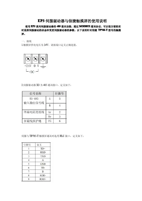
EP3伺服驱动器与信捷触摸屏的使用说明使用EP3系列伺服驱动器的485通讯功能,通过MODBUS通讯协议,可以很方便的实时监控伺服驱动的状态和变更伺服驱动器的参数。
以下说明针对信捷TP765-T型号的触摸屏。
一.接线1.触摸屏供电电压为24V,请按端口定义正确连接。
2.伺服驱动器X3为485通讯接口,定义如下:伺服与TP765-T触摸屏通讯时选用PLC接口,定义如下:注意:接线时,请务必短接伺服X3接口的2、3脚接入终端电阻,信号线的地线也务必连接,否则可能会出现通讯异常。
3.与PC连接示意图注意:与笔记本连接时,需使用RS232转USB的转接线。
二.触摸屏软件编辑打开信捷触摸屏的Touchwin编程软件点击左上角的文件菜单,选择新建栏,出现以下菜单选择相应的触摸屏型号,TP760/5-T,点击下一步选择PLC接口设备为Modbus RTU(显示器为Master),点击设置请选择相应的设置选项,设置通讯参数。
在与伺服通讯前请务必设置伺服的参数与之相匹配。
例:当选择上列设置选项时,请设置伺服的P300号参数为1,P301为2,P302为4。
设置完成后,点击下一步。
因为通讯接口选用的是PLC接口,所以Download接口设备的设置可以忽略,也可以设置成与PLC接口相同的参数,以便接口替换,设置方法相同。
设置完成后点击下一步。
可以选择性填写相应的工程名称、作者及备注,例如:工程1填写完毕,点击完成当出现编辑画面时,便可以操作相应的编辑内容。
下面以监控电机的转速dp-spd 和设置驱动器的P208号参数并保存为例。
其他的设置方法相同。
监控电机的转速:点击菜单的部件栏选择显示栏,点击数据显示,在画面生成显示图标后,出现提示下列窗口站点设备选择PLC口,站点号填写1,对象类型选择4x,数据类型选择word上述填写完成后,再把相关的状态量换算成10进制填入对象空格中。
如电机速度的原始状态量为16进制0x1000,转换成10进制为4096点击显示栏将类型改为十进制,点击应用后,再点击确定,窗口消失。
Z系列扩展BD板用户手册无锡信捷电气股份有限公司资料编号:ZC 02 20210406 3.5目录1. BD板的配置方法 (1)2. BD板精度与相关说明 (2)3. 模拟量输入输出扩展板Z-4AD2DA-A-BD (3)3-1.特点 (3)3-2.一般规格 (3)3-3.外部安装与接线 (3)3-4.输入输出定义号分配 (4)3-5.软件配置 (4)3-6.编程 (5)4. 模拟量温度扩展板Z-3AD3PT-BD (6)4-1.特点 (6)4-2.一般规格 (6)4-3.外部安装与接线 (6)4-4.输入输出定义号分配 (7)4-5.软件配置 (7)4-6.编程 (8)5. 称重扩展板Z-NWT-BD (9)5-1.特点 (9)5-2.一般规格 (9)5-3.外部安装与接线 (9)5-4.称重系统组成 (10)5-5.压力传感器介绍 (11)5-6.模数转换图 (11)5-7.输入定义号的分配 (11)5-8.模块设定 (12)5-9.编程 (13)6. 通讯扩展板Z-NES-BD (15)6-1.特点 (15)6-2.一般规格 (15)6-3.外部安装与接线 (15)6-4.软件配置 (16)7. I/O扩展BD板Z-NXMY-BD (21)7-1.特点 (21)7-2.模块规格 (21)7-2-1 型号说明 (21)7-2-2模块规格 (21)7-3.端子说明 (21)7-4.输入输出定义号分配 (22)7-5.外部安装与接线 (22)7-5-1. 扩展板的安装方法 (22)7-5-2. 输入规格及接线 (22)7-5-3. 输入电源规格 (23)7-5-4. 输出规格及接线 (23)7-6.软件配置 (24)8. 热电偶温度扩展板Z-4TC-BD (25)8-1.特点 (25)8-2.一般规格 (25)8-3.外部安装与接线 (25)8-4.输入输出定义号分配 (26)8-5.软件配置 (26)8-6.编程 (27)9. 编程举例 (28)1. BD 板的配置方法BD 板的配置方法:1)将BD 板正确安装到本体上,BD 板的配置位置如下所示:S/ N: N20140825028MODE: ZG3-30RXINJE2)然后,通过XDPPro 软件进行联机,首先在工程框内右击“PLC1”,然后选择“更改PLC 机型”,给PLC 选型号:ZG3-30,然后在左侧工程栏选择“PLC 配置”-“BD ”(如下图所示):3)选择扩展BD 型号,并配置通道参数,设置完成后点击“确定”,然后下载程序,重新上电方可生效。
信捷PLC (用户手册)信捷PLC (用户手册)1. 概述信捷PLC(可编程逻辑控制器)是一种用于工业自动化控制系统的电子设备。
它的主要功能是接收输入信号,根据预设的逻辑和程序进行处理,并输出相应的控制信号,用于控制各种设备和系统的运行。
本用户手册旨在帮助用户了解和正确使用信捷PLC。
2. 系统要求在开始使用信捷PLC之前,请确保您满足以下系统要求:- 电源电压:输入电压范围为XXVAC-XXVAC,频率范围为XXHz-XXHz。
- 运行环境:温度范围为XX℃-XX℃,湿度范围为XX%-XX%。
- 现场设备:确保连接的设备和传感器与信捷PLC兼容,并按照用户手册的指导正确安装和连接。
3. 硬件组成3.1 主控模块信捷PLC的主控模块是PLC的核心组件,通常由以下部分组成:- CPU模块:负责处理逻辑和控制程序,采用高性能的处理器,具有快速的运算速度和响应能力。
- 电源模块:为PLC提供电源供应,并能实现电源的过载和短路保护。
- 通信模块:用于与其他设备和系统进行通信,支持多种通信接口和协议。
3.2 输入/输出模块输入/输出模块是信捷PLC与外部设备和传感器之间的接口,用于接收和输出控制信号。
它通常包括数字输入模块、模拟输入模块、数字输出模块和模拟输出模块等。
4. 软件操作4.1 编程软件信捷PLC的编程软件提供了一个直观的界面,用于编写和编辑控制程序。
用户可以使用不同的编程语言,如梯形图、指令表等,来表达逻辑和控制流程。
4.2 程序下载和运行编写好的控制程序可以通过编程软件将其下载到信捷PLC的主控模块中。
一旦程序下载完成,PLC即可根据程序的逻辑和条件进行运行,控制各个输入和输出模块的状态。
5. 故障排除与维护5.1 故障排除在使用信捷PLC过程中,可能会遇到一些故障和问题。
用户可以根据以下方法进行排除:- 检查电源供应是否正常工作,确保电压和频率在规定范围内。
- 检查输入/输出模块的连接是否正确,确定信号传输是否正常。

![信捷plc编程手册[1]](https://uimg.taocdn.com/20948a2a192e45361066f5b9.webp)
TP系列工业触摸屏操作手册(基础篇)信捷科技电子有限公司资料编号HMIT TC 01 20090402 298Human Machine InterfaceTP 系列工业触摸屏操作手册(基础篇)第三版前言 ———————————————————— 安全注意事项 ———————————————————— 硬件篇 ———————————————————— 软件篇 ———————————————————— 附录 ———————————————————— 1 2 3 23 161本手册包含了基本的保证人身安全与保护本产品及连接设备应遵守的注意事项,这些注意事项在手册中以警告三角形加以突出,其他未尽事项请遵守基本的电气操作规程。
本设备及其部件只能用于产品目录与技术说明中所叙述的应用,并且只可与信捷认可或推荐的外围厂家出产的设备或部件一起使用。
只有正确地运输、保管、配置与安装,并且按照建议操作与维护,产品才能正常地运行。
Thinget Electronic Co., Ltd. 版权所有未经明确的书面许可,不得复制、传翻或使用本资料或其中的内容,违者要对造成的损失承担责任。
保留包括实用模块或设计的专利许可及注册中提供的所有权力。
责任申明我们已核对本手册的内容与所叙述的硬件和软件相符,因为差错难免,我们不能保证完全一致。
手册内容如有变动,恕不另行通知。
二OO 九 年 四月前言 (1)安全注意事项 (2)硬件篇 (3)1 TP产品概述 (5)1-1.性能特点 (5)1-2.工作流程 (6)2 一般规格 (7)3 安装及维护 (11)3-1.硬件系统结构图 (11)3-2.产品尺寸 (12)3-3.产品安装及使用环境 (13)4 接口说明 (17)软件篇 (23)1 关于TOUCHWIN编辑软件的安装 (25)2 制作一个简单工程 (27)2-1第一步创建一个新的空白的工程 (27)2-2第二步制作开关量和指示灯按钮 (30)2-3第三步离线模拟 (32)2-4第四步在线模拟 (32)2-5第五步下载工程 (34)2-6第六步上传工程 (35)3 编辑画面及窗口 (37)3-1.软件画面的构成 (37)3-2.工程栏 (38)3-2-1 画面操作 (38)3-2-2 窗口操作 (39)3-3.菜单栏 (40)3-3-1 文件 (40)1、新建 (40)2、打开 (40)3、关闭 (40)4、保存 (40)5、另存为 (41)6、下载工程数据 (41)7、在线模拟 (41)8、离线模拟 (41)9、PFW数据 (41)10、系统设置 (42)11、产生组态 (47)12、最近工程 (47)13、退出 (48)3-3-2 编辑 (48)3-3-3 查看 (49)3-3-4 部件 (49)3-3-5 工具 (49)3-3-6 工具 (50)3-3-7 帮助 (50)3-4.画面编辑区 (51)3-5.部件工具栏 (51)3-6.状态栏 (52)4 元件 (53)4-1.全局性操作 (53)剪切 (53)复制 (53)粘贴 (53)撤销 (53)元件公用,元件专用 (53)4-2.画图工具栏 (56)4-3部件工具栏 (69)(1)文字串 (69)(2)动态文字串 (72)(3)变长动态文字 (74)(4)指示灯 (74)(5)按钮 (76)(6)指示灯按钮 (80)(7)画面跳转 (82)(8)数据显示 (84)(9)报警数据显示 (85)(10)字符显示 (86)(11)数据输入 (87)(12)字符输入 (89)(13)中文输入 (90)(14)数据设置 (91)(15)数字键盘 (92)(16)字符小键盘 (92)(17)用户输入 (93)(18)棒图 (94)(19)动态图片 (96)(20)窗口调用 (97)(21)窗口按钮 (98)(22)配方下载 (99)(23)配方上载 (101)(24)功能键 (102)(25)功能域 (109)(26)离散数据柱形图 (111)(27)连续数据柱形图 (112)4-4 显示工具栏 (114)(1)日期 (114)(2)时钟 (114)(3)蜂鸣器 (115)(4)背景灯 (116)(5)刻度 (117)(6)仪表 (118)(7)阀门 (119)(8)管道 (121)(9)水泵 (122)(10)风机 (123)(11)电机 (123)(12)反应罐 (124)(13)变频器报警信息提示 (125)(14)滚屏文字 (126)(15)实时趋势图 (128)(16)历史趋势图 (131)(17)数据移动按钮 (134)(18)XY趋势图 (135)(19)时间趋势图 (138)(20)报警列表 (143)(21)实时事件显示 (144)(22)历史事件显示 (146)(23)通用表格控件 (148)(24)数据采集保存 (150)5 特殊功能 (155)5-1.TP系列触摸屏内部对象 (155)6 常见问题及解决方法 (159)一.密码怎么设置? (159)二.屏与PLC,变频器无法正常通讯,在屏幕上显示“正在通讯中.......”?.. (159)三.屏作为从机如何设置? (159)四.屏无法下载 (159)五.画面设置正确了,离线模拟为什么不行? (159)六.在线模拟为什么一直显示正在通讯中? (160)七.把程序写入屏里面后,在屏幕中间出现了芯片图案? (160)八.触摸屏内的时间怎么更改? (160)九.新建时通讯口设备表里没有用户需要的机型怎么办? (160)十.如何制做触摸屏的下载电缆和通讯电缆? (160)附录 (161)1.与信捷FC/XC系列PLC通讯 (161)2.三菱FX系列,三菱Q系列 (166)3.西门子S7-200/300/400系列 (171)4.欧姆龙C系列 (174)5.光洋S系列 (177)6.台达DVP系列 (181)7.LG M ASTER-K系列PLC (183)8.松下MEWNET FP系列PLC (186)9.施奈德PLC (190)10.永宏FB系列PLC (192)11.丰炜VB系列PLC (196)12.富士SPB系列 (200)13.垦岩KV系列PLC (203)14.艾默生EC20系列PLC (207)15.OEM AX NX7系列 (210)16.博世力士乐I NDRA C ONTROL L40系列 (214)17.OPTO22系列SNAP控制器 (216)18.SAIA-B URGESS PCD系列 (218)——关于产品操作的基本说明 前言首先感谢您购买了信捷TP 系列触摸屏,请在仔细阅读本产品手册后再进行相关操作。

XC系列编程工具XCP Pro(V3.1)用户手册信捷科技电子有限公司资料编号PC 08 20090204 3.1目录1、使用说明 (3)1-2. 安装步骤 (4)1-3. 卸载步骤 (6)2、基本操作 (9)2-1. XCP Pro的打开和关闭 (10)2-2. 创建或打开工程 (11)2-3. PLC类型的添加和删除 (12)3、编辑环境的基本介绍 (14)3-1. 界面基本构成 (15)3-2. 常规工具栏 (16)3-3. PLC工具栏 (17)3-4. 梯形图输入栏 (17)3-5. 其他 (18)3-6. 菜单栏介绍 (19)3-6-1. “文件” (19)3-6-2. “编辑” (20)3-6-3. “查找\替换” (20)3-6-4. “显示” (21)3-6-5. “PLC操作” (21)3-6-6. “PLC设置” (23)3-6-7. “选项” (23)3-6-8. “窗口” (23)3-6-9. “帮助” (23)3-7. 工程栏 (24)3-8. 快捷键介绍 (24)4、简单功能的实现 (25)4-1. 联机 (26)4-2. 程序的上载、下载及PLC状态控制 (27)4-3. PLC初值设定及数据的上传、下载 (28)4-3-1. 初值设定 (28)4-3-2. 数据的上传、下载 (29)4-4. PLC以及模块信息的查询 (29)4-4-1. PLC本体信息 (30)4-4-2. BD板信息 (30)4-4-3. 扩展模块信息 (30)4-4-4. 扫描周期 (31)4-4-5. 时钟信息 (31)4-4-6. 错误信息 (31)4-5. PLC的初始化 (32)4-6. 程序加锁/解锁 (32)4-6-1. 密码设置 (32)4-6-2. 加锁/解锁 (33)4-6-3. 默认解密密码设置 (33)4-7. 打印 (34)5、编程操作 (35)5-1. 编程方式 (36)5-2. 指令符号的输入 (37)5-2-1. 指令提示 (37)5-2-2. 输入接点 (37)5-2-3. 输入线圈 (38)5-2-4. 特殊指令 (41)5-3. 梯形图的编辑 (45)5-3-1. 横线与竖线的操作 (45)5-3-2. 接点与行的操作 (46)5-3-3. 注释的编辑 (47)5-3-4. 梯形图的复制和剪切 (50)5-3-5. 梯形图指令的管理 (51)5-4. 相关配置 (53)5-4-1. PLC串口设置 (53)5-4-2. BD板设置 (54)5-4-3. Can-bus通讯的配置 (54)5-4-4. 断电区域保存的设置 (56)5-4-5. 扩展模块的设置 (56)5-4-6. I/O对应表的设置 (57)5-4-7. 通讯方式设置 (58)5-4-8. TCP/IP设置 (60)5-4-9. 函数功能块列表 (60)5-4-10. 梯形图颜色设置 (61)5-5. 软元件监控 (62)5-5-1. 软元件的注释 (62)5-5-2. 自由监控 (62)5-5-3. 数据监控 (63)5-5-4. 梯形图监控 (63)5-5-5. 信息栏 (64)5-5-6. 状态栏 (65)1、使用说明本章重点说明XC上位机软件XCP Pro的安装系统要求、安装及卸载步骤。

目录0.前言 (2)1.操作注意事项 (2)2.操作台触摸屏画面构成及说明 (3)2-1画面阶层及上下触摸屏画面分配 (3)2-2各画面说明 (3)各画面共同部分 (3)①运转监控画面 (8)①-1掘削条件未成立明细显示Window (12)①-2油脂充填运转设定Window (13)②计测监控画面 (14)③泵启动画面 (17)④推进油缸选择画面 (18)④-1同步设定Window (20)⑤辅助操作画面 (21)⑤-1盾尾油脂操作画面 (22)⑤-1-1自动注入周期设定Window (25)⑤-2超挖刀操作画面 (26)⑤-3铰接操作画面 (28)⑥其他设定画面 (31)⑥-1系统设定Window (32)⑥-2其他设定Window (33)⑥-3土压控制参数设定画面 (34)⑥-4PLC内部AD/DA监控画面 (35)⑥-5异常履历表示画面 (36)⑦异常数据表示画面 (37)⑦-1故障诊断提示Window (38)⑧系统出错表示画面 (39)3.推进油缸操作箱画面构成 (40)3-1画面阶层 (40)3-2各画面的说明 (41)各画面的共同部分 (41)①泵启动画面 (42)②推进油缸操作画面 (43)③其他设定画面 (46)③-1系统设定Window (47)④系统出错表示画面 (48)4.异常内容一览 (49)4-1触摸屏自我诊断异常情况及处理一览 (50)4-2系统出错内容及对应一览 (51)4-3运转关系异常及对应一览 (52)4-4掘削条件未成立导引内容及对应一览 (56)0.前言本说明书为φ6250mm泥土压式盾构操作台及推进油缸操作箱専用的操作説明書(別冊)。
因内容非独立成立,阅读时请参照主机说明书一起使用。
本说明书中的画面为説明用,与实际显示画面可能会有不同,敬请注意。
1.操作注意事項用触摸屏操作时,请仔细阅读以下事项,安全使用。
(1)勿用手指以外的东西操作触摸屏。
硬物操作会损坏触摸屏表面的菜单开关和液晶屏。
Touchpad controllerUser Manual – installation – operationContentsGeneral drawings2 Fixing control panel to wall21. General installation instructions32. Connecting modular cables33. Connecting additional control components43.1 Introduction43.2 Control function ‘switch on/off’43.3 Control function ‘change fan speed’44. Initialising system (prepare for use)55. Operation55.1 Functions of keys55.2 Operation56. Troubleshooting6Fixing control panel to wall 1234General drawings1. General installation instructions— Read this page carefully before starting the installation.— All installation work must be carried out by expert personnel.— Ensure that the appliances are disconnected from the mains before they are opened.— Avoid unnecessary contact with electronic components.Introduction:1. This manual is intended for all Biddle appliances with a built-in electronic interface.2. This manual describes the installation and use of the Biddle electronic control system.3. Several functions in this manual are only available from a certain version of a control system component. These functions are marked. Whenever you change an existing system you should compare the version number on the component with the version number in the manual.Installation details:1. Up to 10 appliances may be connected to one control panel.2. The total length of all modular cables in one system must be less than 100 metres.3. When installing the modular cable care should be taken to avoid interference with the cable by (electro)-magnetic fields as far as possible (therefore do not lay the cable close to high-voltage cables, fluorescent light starters, etc.)Components:The control system comprises the following components:1. Control panel consisting of 3, 4, 5 or 6 keys.2. Built-in interface with 3 or 6 output contacts, depending on the type of appliance.3. Modular cable including modular plugs, for connecting the control panel to one or more appliances. N.B.: B.T. type telecommunication cables are not suitable! The cable can be ordered from Biddle and is available in various lengths.Installation procedure:1. Connect modular cables + install control panel.2. Connect any customised controls, with control components with potential-free contacts.3. Provide all appliances with a power supply.4. Initialise the system.2. Connecting modular cablesA. Appliances with external connectionsType of appliance:— Modular fan coil unit (PS-B)— Air curtain (KW/MW/GW/KE/ME/GE/CAT/CAT-V)— Cassette air heater (KLV/KLV-E/KLVV)B.Appliances with internal connections Type of appliance:— Fan coil unit (B)— Extractor fan cabinetN.B.: The modular cables (X70) can be connected to both connectors (XiS)(see fold-out sheet, page 2).3. Connecting additional control componentsIf you have no control components to install, you can skip this section and go on to section 4 ‘Initialise the system’.3.1 IntroductionAs well as the basic system functions, there is also a possibility of connecting control components (e.g. room thermostat, timer BMS-controlled relay or door switch) to an appliance. Combinations of control components can also be used.N.B.: For remote switching on blocks X62/X72 volt free contacts are required. These contacts are advised to be gold plated and to have a low relay less than 20 m W to handle 1 mA at 5Vdc.Possible control functions:Control function Control range Adaptation to interface ofconnected appliance Connection points onblock X62/X72Connectionsummaryswitch on/off one appliance (local)none terminals T and G see § 3.2 switch on/off all appliances in system (general)remove jumper 6terminals T and G see § 3.2 change fan speed one appliance (local)none terminals D, P and G see § 3.3 change fan speed all appliances in system (general)remove jumper 5terminals D, P and G see § 3.3 N.B.: The function ‘switch on/off’ does not apply to the KLVV-unit. Consult the user manual of the unit when you want to connect control components to terminals T and G.3.2 Control function ‘switch on/off’1. Remove T-G bridge (X62/X72. see fold-out sheet, page 2) only from the appliance towhich the control component is to be connected.2. Connect the control component between T and G.— Contact made between T and G: Applicance stand-by.— No contact between T and G: Appliance/system off.3. General switching If the control function is to apply to the whole system, remove jumper 6(X64). This should only be done in the appliance to which the control component isconnected. Place the jumper on the reserve positions intended for it (X65), so that it can beused again later.3.3 Control function ‘change fan speed’1. Connect the control component between D and/or P and G (X62/X72, see fold-out sheet, page2). Important: do not disconnect T-G bridge.— Contact made between D and G : Appliance/system runs 1 speed higher than the controlpanel indicates (both speed and electric heating).— No contact between D and G Appliance/system working as indicated on the control panel.— Contact made between P and G Appliance/system runs at fan speed three (electric heatingstage remains unchanged, either one or two).— No contact between P and G Appliance/system working as indicated on the control panel.— Contact made between D, P and G: Appliance/system runs at fan speed three and electricheating stage two.N.B.: The functions using terminals P and G only are available from interface version V4.0Rev.06. Code IC 10 in the illustration on page 2 shows where you can find the version number.2. General switching: If the control function is to apply to the whole system, remove jumper 5(X64) as indicated in the facing illustration. This should only be applied to the appliance towhich the control component is connected. Place the jumper on the reserve positions intendedfor it (X65), so that it can be used again later.NB: General switching’ of the contact between P and G requires control pad version V2. IRev.02 or higher and interface version V4.O Rev.07 or higher. You can find the versionnumber on the printed circuit board of the control pad. In an existing system the control padcould be of a previous version. If the contact between P and G should still apply to the wholesystem, you should order a new control pad from Biddle.3. If the electric heating is not to be stepped up at the same time, remove jumper 4 (X64) asindicated in the illustration. This should be done in each appliance for which the function is required. Place the jumper on the reserve positions intended for it (X65), so that it can be used again later.14564. Initialising the system (prepare for use)When to use:1. On first installation.2. On each extension of the system.3. When checking cables.To start the procedure:1. Press keys 1, 2 and 3 simultaneously.—After 10 seconds the LEDs on keys 1 and 2 will start to flash. This flashing will continue for two minutes.— The LED on key 3 will then flash the same number of times as there are appliances in the system. The system is now ready for use.5. Operation5.1 Functions of keysLED lights when speed setting is ‘low’.LED flashes during initialisation.— Set speed to ‘low’.— Switch off appliance.— Start initialisation.LED lights when speed setting is ‘medium’LED flashes during initialisation.— Set speed to ‘medium’.— Switch off appliance.— Start initialisation.LED lights when speed setting is ‘high’.LED indicates number of appliances connected when initialisation is complete.— Set speed to ‘high’.— Switch off appliance.— Start initialisation.LED lights when electric heating is set to ‘low’.— Set electric heating to ‘low’.— Switch off electric heating.— Set electric heating to ‘low’ and speed to ‘low’.LED lights when electric heating is set to ‘high’.— Set electric heating to ‘high’.— Switch off electric heating— Set electric heating to ‘high’ and speed to ‘medium’.LED-R lights when setting is ‘Recirculate’ or standby.LED-V lights when setting is ‘Ventilate’.— Set air intake valve to ‘Ventilate’.— Set air intake valve to ‘Recirculate’.5.2 OperationA.Turn on appliance : Press key 1, 2, 3, 4 or 5.B.Turn off appliance : Press speed key (1, 2 or 3) on which the LED is illuminated. LED-R (if present) remains illuminated.Safety functions electric heating:1.The following scenarios will automatically be corrected:— Speed off, electric heating on.— Speed low, electric heating high.2. Appliance operates differently from control panel:If the appliance has just been switched off, it may start running again spontaneously.This is in order to discharge the heat stored in the heating elements.6.TroubleshootingAppliance not working:Check point Possible cause Action1no voltage on appliance check power supply to appliance2system not yet initialised start initialisation; see section 4 ‘Initialising the system’3poor contact in modular plug;check contacts (ensure plastic packaging is completely removed)4no bridge between terminals T and G fit bridge between terminals T and G on block X62/72. (see section 3‘Connecting Customised Control components’)5fuse(s) in appliance defective replace fuse (only to be done by skilled personnel)Appliance not working as expected:Check point Fault Possible cause Action/explanation1appliance (with electric heating)starts working spontaneously continued running of electricallyheated appliancesBiddle safety function; see section 5‘Operation’control components are notproperly connectedcheck system; see section 3‘Connecting Customised ControlComponents’2appliance works differently fromexpectationthe jumpers(l-3 red) on the interface are no longer in accordance with factory setting check jumper position against Specifications for factory setting jumper block X643electric heating not working appliance has overheated check maximum thermostat(see appliance manual) Factory setting jumper block X64Appliance type Jumper 1Jumper 2Jumper 3Jumper 4-6 appliance with electric heating with 2 positions present open present present CAT-air curtain open present present present KLV-E open present open present KLVV open open open presentall other appliances present present present present。
TP\TH\TG触摸屏C函数功能块用户手册无锡信捷电气股份有限公司资料编号:HC 10 20120628 2.D目录前言 (1)1 函数功能块制作 (2)2函数功能块说明 (4)2.1书写方式 (4)2.2函数类型 (4)2.3预定义数据类型 (5)2.4预定义宏指令 (6)2.5系统函数 (6)2.5.1 Read/ Write (6)2.5.2 Reads/Writes (7)2.5.3 Enter/ Leave (7)2.5.4 Send (7)2.5.5 Receive (8)2.5.6 Malloc (8)2.5.7 Free (8)2.5.8 Delay (9)2.5.9 ScreenJump (9)2.5.10 OpenWindow (9)2.5.11 CloseWindow (9)2.5.12 Beep (9)2.5.13 WakeScreen (10)2.5.14 Crc (10)2.5.15 BendCalYDepth (10)2.5.16 DCMapSetBackColor (11)2.5.17 DCMapDrawLine (11)2.5.18 DCMapDrawRect (11)2.5.19 DCMapDrawCircle (12)2.5.20 DCMapDrawEllipse (13)2.5.21 DCMapDrawCircleArc (13)2.5.22 DCMapDrawEllipseArc (14)2.5.23 DCMapClear (15)2.6宏操作 (15)2.6.1 Max (15)2.6.2 Min (15)2.6.3 MAKEWORD (16)2.6.4 MAKEDWORD (16)2.6.5 LOBYTE (16)2.6.6 HIBYTE (16)2.6.7 LOWORD (16)2.6.8 HIWORD (16)2.7 C语言常见库函数 (17)2.7.1 abs (17)2.7.2 acos、asin、atan (17)2.7.3 cos、sin、tan (17)2.7.4 log (17)2.7.5 log10 (18)2.7.6 pow (18)2.7.7sqrt (18)2.7.8 rand (18)2.8触摸屏内部对象 (19)2.8.1 PSW对象 (19)2.8.2 PSB对象 (19)3 工程示例 (20)3.1 数据比较 (20)3.2 C函数实现自由通讯 (22)3.3 加减乘除运算 (25)3.4 C函数画直线、矩形、圆、椭圆、圆弧、椭圆弧 (30)4 常见问题 (35)4.1如何对正在编辑C功能函数程序进行编译? (35)4.2如何在C功能函数块中读取PLC参数值或者写入PLC参数值? (35)4.3使用Read、Write、Reads、Writes函数快捷方法? (36)附录1 C标准库函数的调用限制 (37)附录2 C函数使用注意事项 (38)前言相较于TP、TH、TG系列触摸屏软件中简单的工程命令、高级功能指令,新添加的C函数功能块,使触摸屏可以完成更多、更复杂的运算和通讯要求,使系统功能得到了更大限度的发挥,更好地满足客户的实际需求。
信捷PLC用户手册关键信息项:1、产品名称:信捷 PLC2、产品型号:____________________________3、适用范围:____________________________4、功能描述:____________________________5、技术规格:____________________________6、操作指南:____________________________7、安全注意事项:____________________________8、维护与保养:____________________________9、售后服务:____________________________1、产品介绍11 信捷 PLC 是一款高性能的可编程逻辑控制器,旨在满足各种工业自动化控制需求。
12 其具有稳定性高、可靠性强、编程灵活等特点,适用于多种行业和应用场景。
2、产品型号21 详细列出不同型号的信捷 PLC 及其主要特点和差异。
22 说明各型号的适用范围和推荐应用领域。
3、适用范围31 工业生产中的自动化生产线控制。
32 机械设备的运动控制。
33 智能建筑系统的自动化管理。
34 其他需要逻辑控制和自动化处理的场景。
4、功能描述41 逻辑运算功能,包括与、或、非等基本逻辑操作。
42 定时计数功能,可实现精确的时间控制和事件计数。
43 数据处理功能,能够进行数据的存储、传输和运算。
44 通信功能,支持多种通信协议与其他设备进行数据交换。
5、技术规格51 输入输出点数及类型。
52 工作电源要求。
53 处理速度和存储容量。
54 环境适应能力,如温度、湿度、防尘等。
6、操作指南61 编程软件的安装和使用。
62 编程语法和指令系统。
63 程序下载和上传的方法。
64 在线调试和监控功能的操作。
7、安全注意事项71 安装和接线时的安全要求,避免触电和短路。
72 运行过程中的防护措施,防止误操作和意外事故。