康明斯CM570发动机电控系统电路图
- 格式:pdf
- 大小:1.38 MB
- 文档页数:3
《柴油电喷发动机电路图集大全》附电脑针脚端子图页数: 500 页年代: 2015 年第一版目录前言(序)博世(BOSCH高)压共轨系统电路图与故障码表 (1)解放J6 发动机与整车电路图 (6)解放载货汽车(电装系统)电路图与针脚图 (14)康明斯ISDe-Cm2150发动机电控系统电路图 (22)康明斯ISBE(6 缸)电路图电控系统电路图 (24)康明斯ISBE(4 缸)电路图电控系统电路图 (29)康明斯ISB4/ISBe 发动机电控系统电路图 (34)康明斯ISDE(6 缸)发动机电控系统电路图 (36)康明斯ISDE(4 缸)电路图电控系统电路图 (39)康明斯ISLE(6 缸)电路图电控系统电路图 (42)康明斯ISLE(4 缸)电路图电控系统电路图 (45)康明斯CM570发动机电控系统电路图 (48)康明斯ISC 发动机电控系统电路 (50)日野P11C发动机电控系统电气资料 (54)日野E13C发动机电控系统电气资料 (65)日野J05E/J08E 发动机电控系统电气资料 (77)日野J05 发动机ECU电控系统电路图与针脚图 (81)日野J08 发动机ECU电控系统电路图与针脚图 (82)陕汽德龙F2000 整车电气线路图 (85)陕汽德龙F3000 整车电气线路图 (92)陕汽德龙F3000 WP10/WP12发动机电控系统 (97)陕汽德御整车电气线路图 (103)陕汽奥龙整车电气线路图 (111)上柴8DK发动机ECU电控电路图 (119)潍柴WD615国四(DENSO系统)电路图带SCR尿素系统123潍柴国四发动机BOSCH EDC1系7 统电路图与针脚图 (125)潍柴WP10电控系统线路图 (129)锡柴(BOSCH EDC 7共)轨电路图与ECU针脚义 (132)锡柴6DE发动机(单体泵)系统电路图 (135)锡柴CA4DF3发动机电控系统电气资料 (136)锡柴CA4DL发动机电控系统电气资料 (142)锡柴CA6DL发动机电控系统电气资料 (149)锡柴CA6DL1发动机电控系统电气资料 (159)锡柴CA6DL2发动机电控系统电路图 (163)锡柴CA6DL32发动机电控系统电气资料 (165)锡柴4DL 发动机电控系统电路图 (166)锡柴6DL1 发动机电控系统电路图 (167)锡柴CA6DL1-E3 发动机电装共轨系统电控原理图 (168)锡柴CA6DL1-32E3发动机电装共轨系统电控原理图(带继电器)169锡柴CA6DL1-32E3发动机电装共轨系统电控原理图(不带继电器)170锡柴CA4DL1-20E3发动机电控系统电路(带继电器) (171)锡柴CA4DL1-20E3发动机电控系统电路(不带继电器) (172)锡柴CA4DF3-13E3发动机电控系统电路图 (173)锡柴CA6DL2-35E3发动机电控系统电路图 (174)锡柴6DF3、6DL2 (电装BOSCH共轨)电控系统电路图 (175)玉柴(国四)YC6L-40 柴油机SCR 整车线束电路图 (176)玉柴BOSCH共轨发动机线路图与针脚定义 (179)玉柴YC4FA EDC16博世共轨电控系统电路图 (181)玉柴YC4F 德尔福共轨系统电控系统电路图 (183)玉柴YC6G240-30 (德尔福单体泵)电控系统电路 (185)玉柴欧四发动机系统电路图(添蓝)SCR部件针脚图 (187)重汽豪沃EGR车型全车电气线路图 (192)重汽豪沃共轨车型全车电气线路图 (203)重汽豪沃A7 EGR车型全车电气线路图 (211)重汽豪沃WD615国(三)发动机电控系统电路图+针脚定义222重汽豪沃D12发动机电控系统电路图+故障码 (227)大柴道依茨BFM1013/2012/2013发动机电控系统电气资料.. 232大柴道依茨发动机(单体泵)电控系统图+针脚图.. 235大柴道依茨发动机BOSCH EDC16UC4单0 体泵系统( 6 缸)电路图241大柴道依茨发动机BOSCH EDC16UC4单0 体泵系统( 4 缸)电路图243朝柴BOSCH共轨电控系统电脑ECU端子和电路图 (245)德尔福(DELPHI)高压共轨DCM 3.1系统针脚电路图+故障码.. 247电装(DENSO高)压共轨4DL 6DL系统电气电路图 (251)电装(DENSO高)压共轨电控系统针脚资料 (255)电装(DENSO高)压共轨系统故障码表 (259)东风天龙DFL1203A整车电气线路图 (261)东风天锦D530整车电气线路图 (264)东风柳汽霸龙507 电气线路图 (268)东风大力神DFL3251A整车电气线路图 (269)北汽福田欧曼整车电路图 (271)北汽福田欧曼雄狮电路图 (273)北汽福田欧曼上柴发动机电控系统+端子图 (276)北汽福田欧曼上柴SC9DF发动机电控系统与故障码 (280)依维柯索菲姆SOFIM 发动机BOSCH EDC-MS6.共3 轨系统线路图. 284依维柯IV012-2 NEF 发动机电控系统线路图 (287)依维柯SOFIM 8140.43S3 博世共轨EDC16电控系统电路 (291)依维柯EV01 红岩发动机BOSCH EDC7UC3电1 控系统电路 (293)云内动力D16TcI/D19TcI 发动机电气资料 (295)云内动力YN33 30 发动机电控系统电路图 (299)杭发电装发动机电控系统电路图 (301)杭发欧三(徐工吊车)原理图 (303)金龙斗山DV10发动机电控系统线束电气资料 (304)斗山大宇DV11 发动机ECU 电控系统电路图 (312)斗山大宇DL06 发动机电控系统电路图 (315)斗山大宇DL08 发动机ECU 电控系统电路图 (317)南岳单体泵电磁曲轴发动机ECU电路图( 4 缸 5 线油门踏板)320南岳单体泵电磁曲轴发动机ECU电路图( 6 缸 5 线油门踏板)322南岳单体泵电磁曲轴发动机ECU电路图(4缸6 线油门踏板)... 324南岳单体泵电磁曲轴发动机ECU电路图(6缸6 线油门踏板) (326)南岳单体泵霍尔曲轴发动机ECU电路图(4缸5 线油门踏板) (328)南岳单体泵霍尔曲轴发动机ECU电路图(6缸5 线油门踏板) (330)南岳单体泵霍尔曲轴发动机ECU电路图(4缸6 线油门踏板) (332)南岳单体泵霍尔曲轴发动机ECU电路图(6缸6 线油门踏板)... 334五十铃6wAl—Tc 发动机电控系统电气资料 (336)五十铃6wGl一Tc 发动机电控系统电气资料 (340)江铃N 系列全顺Jx493ZLQ发动机电控系统电气资料 (344)江铃T 系列欧Ⅲ发动机电控系统电气资料 (349)庆铃600P发动机4KHl —Tc电控系统 (350)五十铃6HK1 电路电控系统电路图 (355)五十铃6HK1(带GVNR线束)发动机电控系统电路图 (358)五十铃6WA1-TC电路图与针脚定义 (360)五十铃6WG1发动机电控系统电路图 (364)五十铃4JH1-TC 发动机电控系统电路图 (367)五十铃100P 4JB1 发动机电控系统电路图 (373)五十铃4JJ1 发动机电控系统电路图 (375)五十铃6HE1 发动机电控系统电路图 (377)五十铃4HE1 发动机电控系统电路图 (378)五十铃6SD1 发动机电控系统电路图 (379)江铃BOSCH电控EDC16C39H电路图 (380)江淮FA140发动机电路图 (382)江淮瑞风FA080 2.8L 柴油发动机电控系统电路图 (283)长城哈弗4D28TC 发动机电控系统电路图 (385)现代特拉卡aCovec2.5 发动机电路图与针脚图(AT) (389)现代特拉卡aCovec2.5 发动机电路图与针脚图(MT) (391)威特WP2000单体泵电控系统电气资料 (393)威特单体泵(东风乘龙)发动机电控系统电路图.. 399威特单体泵(玉柴)电路图 (401)住友机械五十铃发动机4HK1 电控系统电路图及ECU 端子定义 . 405日立挖机ZX200-3、ZX240-3、ZX270-3 电控系统电路图 (408)日立挖机EC210B-07 发动机电控系统电路 (410)神钢SK330 电控系统电路 (413)神钢SK200 电控系统电路图 (414)神钢SK350LC-8 电控系统电路 (416)神钢SK210LC-8 电控系统电路图 (418)三菱FUSO 4M50发动机电控系统电路图 (420)三菱FUSO 6M70发动机电控系统电路图 (421)卡特C-9 发动机ECU 电控系统接线图 (422)卡特325C 挖掘机发动机电控系统电路图 (423)卡特330C 挖掘机发动机电控系统电路图 (424)加藤HD820V发动机电控系统电路图 (425)天然气玉柴EPR 6G 发动机电控线路图 (428)天然气玉柴EPR 6M 6J 4G 发动机电控线路图 (429)伍德沃德天然气发动机ECU 线路图 (430)天然气(玉柴 6 缸)电路图 (432)天然气(玉柴ECI系统)4 缸 6 缸CNG增压发动机电路图. 433天然气(玉柴ECI系统)4 缸 6 缸LNG增压发动机电路图. 435天然气(玉柴ECI系统)6M 6J 4G 整车线路图 (437)华菱重卡货车汽车灯光系统电气线路图 (440)北京BJ493ZQ3发动机电路图 (452)三菱6M60 电装发动机电路图与ECU端子 (453)雷诺DCI11 发动机ECU 端子定义 (455)日产UD GE1(3 I 型)电控系统电路图 (458)日产UD GE1(3 II 型)电控系统电路图 (461)日产UD-FE6TC( A 型)电控系统线路图 (464)日产UD-FE6TC( B 型)电控系统线路图 (466)日产UD MD9、L MD9M发动机电控系统电路图 (468)日产UD MD9L/MD9发M 动机电控系统针脚资料 (472)MAN发动机BOSCH EDC MS发5 动机电路图 (474)斯堪尼亚BOSCH EDC MS发5 动机电控系统电路 (475)沃尔沃单体泵发动机电控系统电路图 (476)EDC17尿素单元电路图 (478)自主品牌+天纳克系统电路图 (479)三合一电脑+1.5 代天纳克尿素单元电路图 (480)常用车型诊断座位置--OBD端子说明 (481)柴油电控发动机(数据流)标准值-博世福田上柴潍柴锡柴等 (490)常用汽车仪表(报警标志)示意图 (497)电话QQ: 网址潍柴锡柴玉柴朝柴上柴康明斯依维柯大柴道依茨江铃威特南岳云内三菱庆铃江淮北汽杭发日野日产等随着柴油技术日益发展,人们越来越发现柴油机的无穷魅力、高扭矩、高寿命、低油耗、低排放,柴油机成为解决汽车能源问题最现实和最可靠的手段,先后从国二机械喷射, 到国三电喷, 如今发展到国四排放标准.为环保,减少汽车尾气排放污染,工信部定于2014年12 月31 日废止适用于国家第三阶段汽车排放标准柴油车产品《公告》,2015年1月1日起国Ⅲ柴油车产品将不得销售,国家实行国Ⅳ 排放,在国Ⅲ发动机EGR(大泵),共轨的,单体泵的基础上,演变成国Ⅳ发动机,电控系统类似不变, 只是在排气系统上加装了一套SCR尾气处理系统(俗称尿素罐),燃烧尿素,控制对象是NOx和颗粒物PM,达到净化尾气保护环境的目的.对于维修人员而言,市面上存在大量电控机车处于维修阶段,急需掌握电喷发动机有下面几种技术:1. 电控高压共轨技术2. 电控单体泵技术3. 电控泵喷嘴技术4. 涡轮增压、EGR废气循环、中冷技术5. 尾气净化SCR原理特此本部精心收集整理了本套电路图集,配合光盘视频与图文教程,让修理人员在技术上得心应手后续推出: 第二版(加Q期待2016 版)2015.10 (第一版)。
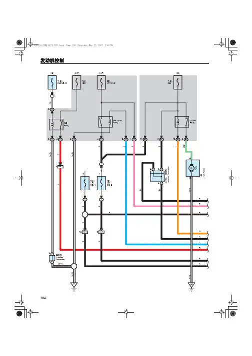
1A1121BA1A1RR20BATT 3435ST163(1)1 : Shielded96ETHW+B HT1A 53B(1)(5)1 : Shielded2 : w/ Smart Entry & Start System3 : w/o Smart Entry & Start System4 : w/ Mirror Heater5 : w/o Mirror HeaterBA25(3)(2)BA21092BG(2)(3)(3)(2)(3)G(2)3 : w/o Smart Entry & Start System 2 : w/ Smart Entry & Start System G (7)2019W(6)G (6)AE323W(7)6 : Optitron Meter7 : Except Optitron MeterG(7) W(6) G(6)32W(7)P(7)BR(7)V(7)V(7)W(7)G(7)P(7)W(7) LED Driver6 : Optitron Meter7 : Except Optitron MeterP(7)W(7)P(7)BR(7)V(7)V(7)W(7)G(7)89(4)25(3)(2)(1)(6)(5)AE324 1 : w/ Smart Entry & Start System and/or w/ Automatic Light Control 2 : Except 1 3 : w/ VSC 4 : w/o VSC5 : Automatic A/C6 : Manual A/C7 : w/ Parking Assist 9 : w/ VSC and/or w/ Parking Assist (Back Guide Monitor)1 : w/ Smart Entry & Start System and/or w/ Automatic Light Control 8 : w/ Smart Entry & Start System(1)(1)3511A1H LP RH LO (2)10AH LP RH LO (3)12H LP LH LO (2)10AH LP LH LO (3)3 : Except HID Type2 : HID TypeA3 B (2)(2)1 : w/ Smart Entry & Start System 1211W W4A11 A31334A(1)15(2)(1)(2)211 : w/ Automatic Light Control2 : w/o Automatic Light Control3 : Optitron Meter4 : Except Optitron Meter2130Junction Connector1371 : w/ Rear Spoiler2 : w/o Rear Spoiler Junction ConnectorBA1 2B B60Back Up Light Switch Assembly7(8)(1)918854A13(1)(1)8 : w/ Smart Entry & Start System and/or w/ Automatic Light Control 2 : w/o Automatic Light Control1 : w/ Automatic Light Control 11 : w/ Smart Entry & Start System4BREC2EL34ILL+Junction Connector3 : Manual A/C4 : Automatic A/CV(7)W(6)P(6)(9)(10)(9)(10(7)6 : Optitron Meter7 : Except Optitron Meter 5 : w/ Steering Pad SwitchV(7) W(6) P(6)(7) 9 : w/ Navigation System10 : w/o Navigation System149(3)P(2)236212P(2)21 : w/ Smart Entry & Start System2 : w/o Smart Entry & Start System3 : w/ Smart Entry & Start System and/or w/ Automatic Light Control9IE14A 744C 3M287(4)4A2SKL191 : w/ Smart Entry & Start System2 : w/o Smart Entry & Start System78IE1(3)3 : w/ Smart Entry & Start System and/or w/ Automatic Light Control4 : Except 3EM2+51M14No. 3 Door ControlReceiver Electrical Key Antenna 27(3)(4)444A4A92211EM114C(3)(4)2B122211 : w/ Smart Entry & Start System2 : w/o Smart Entry & Start System3 : w/ Smart Entry & Start System and/or w/ Automatic Light Control4 : Except 35 : Optitron Meter6 : Except Optitron Meter(3)(4)(6)(6)(6)(6)(6)6 : Except Optitron Meter(6)(6)LED Driver(6)(6)(6)。


FUEL RAIL PRESSURE SENSORT orque=3N•m[27in-lb]Pressure(mPa)Pressure[psi]Voltage(VDC) 000.50405801 1.397010153 2.0610014504 2.7214020305 3.6118026107 4.50ACCELERATOR PEDAL(IVS,ISS,&APS)Idle Validation Circuit Resistance:For ON and OFF-IDLE statesISS-MAX Closed Circuit Resistance<125ΩISS-MIN Open Circuit Resistance>100kΩACCELERATOR PEDAL and REMOTE ACCELERATOR Accelerator Position Sensor Coil Resistance:Between supply and return wires•2000to3000ohmsBetween supply and signal wires(released pedal)•1500to3000ohmsBetween supply and signal wires(depressed pedal)•200to1500ohmsNOTE:Released resistance minus depressed resistance must be1000ohms.FAULT CODE INFORMATIONFAULT CODE LAMP PID(P)SID(S)FMISPN(S)FMI REASON EFFECT(Only when fault code is active)111 Red S2541262912ECM internal hardware error.Possible no effect or engine will run rough or notstart.122 Y ellow P10231023High voltage detected at the intake manifold pres-sure sensor signal pin28of the engine harness.Engine can derate to no-boost fueling.123 Y ellow P10241024Low voltage detected at intake manifold pressuresensor signal pin28of the engine harness.Engine can derate to no-boost fueling.131 Red P09130913High voltage detected at accelerator position signalpin83of the OEM harness.Engine idles when idle validation switch indicates idleand ramps up to a default set speed when the idlevalidation switch indicates off-idle.132 Red P09140914Low voltage detected at accelerator position signalpin83of the OEM harness.Engine idles when idle validation switch indicates idleand ramps up to a default set speed when idle vali-dation switch indicates off-idle.133 Red P02939743High voltage detected at remote accelerator positionsignal pin85of the OEM harness.Engine will not respond to remote accelerator input.134 Red P02949744Low voltage detected at remote accelerator positionsignal pin85of the OEM harness.Engine will not respond to remote accelerator input.135 Y ellow P10031003High voltage detected at oil pressure signal pin33of the engine harness.Default value used for oil pressure No engine protec-tion for oil pressure.141Y ellow P10041004Low voltage detected at oil pressure signal pin33ofthe engine harness.Default value used for oil pressure.No engine protection for oil pressure.143 Y ellow P100110018Oil pressure signal indicates oil pressure below thelow engine protection limit.Power and/or speed derate and possible engine shut-down if engine protection shutdown feature is en-abled.144 Y ellow P11031103High voltage detected at coolant temperature signalpin36of the engine harness.Default value used for coolant temperature.No engine protection for coolant temperature.145 Y ellow P11041104Low voltage detected at coolant temperature signalpin36of the engine harness.Default value used for coolant temperature.No engine protection for coolant temperature.146 Y ellow P110110Coolant temperature signal indicates coolant tem-perature has exceeded the engine protection limit.Power derate and possible engine shutdown if engineprotection shutdown feature is enabled.151 Red P110110Coolant temperature signal indicates coolant tem-perature has exceeded the engine protection limit.Power and/or speed derate and possible engine shut-down if engine protection shutdown feature is en-abled.153 Y ellow P10531053High voltage detected at intake manifold tempera-ture signal pin29of the engine harness.Default value used for intake manifold temperature.No engine protection for intake manifold temperature.154 Y ellow P10541054Low voltage detected at intake manifold tempera-ture signal pin29of the engine harness.Default value used for intake manifold temperature.No engine protection for intake manifold temperature.155 Red P105105Intake manifold air temperature signal indicates in-take manifold air temperature is above the engineprotection limit.Power and/or speed derate and possible engine shut-down if engine protection shutdown feature is en-abled.187 Y ellow S232410804Low voltage detected on the ECM voltage supplyline to fuel rail pressure sensor pin12of the engineharness.Possible low power.197 Y ellow P111111118Coolant level signal indicates coolant level has ex-ceeded the engine protection limit.Power and/or speed derate and possible engine shut-down if engine protection shutdown feature is en-abled.198 Mainte-nance S122416614Error detected on warning lamp circuit.Error couldbe open circuit,short circuit to battery or ground.Warning(yellow)lamp will not operate correctly.212Y ellow P17531753High voltage detected at the oil temperature signalpin35of the engine harness.Default value used for oil temperature.No engine protection for oil temperature.213Y ellow P17541754Low voltage detected at the oil temperature signalpin35of the engine harness.Default value used for oil temperature.No engine protection for oil temperature.221Y ellow P10831083High voltage detected at the ambient air pressuresignal(internal to the ECM).Possible black smoke.Engine protection system canbe affected.Altitude derate will not function.227 Y ellow S232310803High voltage detected on the ECM voltage supplyline to fuel rail pressure sensor pin12of the engineharness.Possible low power.234 Red P190190Engine speed signal indicates engine speed hasexceeded the overspeed limit.Fuel to injectors disabled until engine speed falls be-low the overspeed limit(3500rpm fault set,3200rpmbegin fueling).235 Red P11111111Coolant level signal at pin59of the OEM harnessindicates coolant level is low.Power and/or speed derate and possible engine shut-down if engine protection shutdown feature is en-abled.238 Y ellow S23246204Low voltage detected on the ECM voltage supplyline to the oil pressure sensor pin9of the engineharness.Default value used for oil pressure sensor connectedto this+5VDC supply and no engine protection foroil pressure.239 Y ellow S23236203High voltage detected on the ECM voltage supplyline to the oil pressure sensor pin9of the engineharness.Default value used for oil pressure sensor connectedto this+5VDC supply and no engine protection foroil pressure.241Y ellow P08420842Vehicle speed signal on pins56and74of the OEMharness has been lost.Engine speed limited to‘‘Max.Engine Speed withoutVSS’’.Cruise control,gear-down protection and theroad speed governor will not work.T rip informationdata that is based on mileage will be incorrect.FAULT CODE LAMP PID(P)SID(S)FMISPN(S)FMI REASON EFFECT(Only when fault code is active)244 Y ellow S23846234Error detected on one or more of the lamp circuits.Error could be open circuits,or short circuits to bat-tery or ground on any lamp except diagnostic lamp.Lamp will not come on during the key on bulb test ifthere is an open circuit or short circuit to battery.Lamp will stay on if shorted to ground.261Y ellow P17417416High fuel temperature has been detected.Voltagesignal at the fuel temperature signal pin34of theengine harness indicates fuel temperature above71°C[160°F],Calibration-dependent progressive power derate andengine shutdown with increasing time after alert.263 Y ellow P17431743High voltage detected at the fuel temperature sen-sor signal pin34of the engine harness.Default value used for fuel temperature.Possible low power.No engine protection for fueltemperature.265 Y ellow P17441744Low voltage detected at the fuel temperature sensorsignal pin34of the engine harness.Default value used for fuel temperature.Possible low power and no engine protection for fueltemperature.266 Red P174174Fuel temperature signal indicates fuel temperaturehas exceeded the engine protection limit.(90°C194°F)Power derate and possible engine shutdown if engineprotection shutdown feature is enabled.269 Red S217211952Engine rpm is detected when the vehicle antitheftfeature is active.Engine will not start.271Y ellow S151413474Short circuit detected on the electronic fuel controlactuator circuit.Possible low power.Engine will die and not restart.272 Y ellow S126313473Open circuit detected on the electronic fuel controlactuator circuit.Power derate to calibrated value.291 Red S2489625Incorrect key used on the Immobilizer™equipment.Engine will not start.292 None P44114441Coolant temperature has exceeded the Leyland/DAF specification.Possible engine derate.293 Y ellow P44134413High voltage detected at the OEM temperature sen-sor signal pin88of the OEM harness.Default value used for the OEM temperature.294 Y ellow P44144414Low voltage detected at the OEM temperature sen-sor signal pin88of the OEM harness.Default value used for the OEM temperature.296 Red P22314138714OEM pressure out-of-range has been detected.Volt-age signal at the OEM pressure signal pin indicatesOEM pressure above OEM specified threshold.Calibration dependent progressive power derate andengine shutdown with increasing time after alert.297 Y ellow P223313873High voltage detected at the OEM pressure sensorsignal pin82of the OEM harness.Default value used for the OEM pressure.298 Y ellow P223413874Low voltage detected at the OEM pressure sensorsignal pin82of the OEM harness.Default value used for the OEM pressure.311Y ellow S00166516Short circuit detected in the injector bank1circuit.For a six-engine bank1consists of cylinders1,3,and5.For a four-cylinder,engine bank1consists ofcylinders1and3.Low power as a result of cylinders not firing.319 Mainte-nance P25122512Real Time Clock lost power.Unswitched batterypower to the electronic control module(ECM)hasbeen interrupted.None on performance.Data in the ECM may nothave accurate time and date information.321Y ellow S00466546Short circuit detected in the injector bank2circuit.For a six-cylinder,engine bank2consists of cylin-ders2,4,and6.For a four-cylinder,engine bank2consists of cylinders2and4.Low power as a result of cylinders not firing.322 Y ellow S00156515No current detected at number1injector driver orreturn pin when the voltage supply at the harness ison or high resistance detected on injector number1circuit.Possible misfire on cylinder1.Engine will run rough.323 Y ellow S00556555No current detected at number5injector driver orreturn pin when the voltage supply at the harness ison or high resistance detected on injector number5circuit.Possible misfire on cylinder5.Engine will run rough.324 Y ellow S00356535No current detected at number3injector driver orreturn pin when the voltage supply at the harness ison or high resistance detected on injector number3circuit.Possible misfire on cylinder3.Engine will run rough.325 Y ellow S00656565No current detected at number6injector driver orreturn pin when the voltage supply at the harness ison or high resistance detected on injector number6circuit.Possible misfire on cylinder6.Engine will run rough.329 Y ellow S23314107714Rail pressure can not be maintained at maximumpumping capacity.Engine will shut down.331Y ellow S00256525No current detected at number2injector driver orreturn pin when the voltage supply at the harness ison or high resistance detected on injector number2circuit.Possible misfire on cylinder2.Engine will run rough.332 Y ellow S00456545No current detected at number4injector driver orreturn pin when the voltage supply at the harness ison or high resistance detected on injector number4circuit.Possible misfire on cylinder4.Engine will run rough.FAULT CODE LAMP PID(P)SID(S)FMISPN(S)FMI REASON EFFECT(Only when fault code is active)341Y ellow S25326302Memory in the ECM has been corrupted.Possible no effect or engine will run rough or notstart.343 Y ellow S2541262912Internal ECM error.None on performance or severe derate.352 Y ellow S232410794Low voltage detected on the ECM voltage supplyline to boost pressure,OEM pressure,and coolantlevel sensor,as well as the remote accelerator.Default values used for sensors connected to this+5VDC supply.Possible default to idle speed.Lowpower can occur because fueling defaulted to noboost fueling.Also,possible loss of engine protectionfor the sensors.381Y ellow S2371162611Error detected in cold start aid relay1enable circuitat pin16of the OEM harness.The intake air heater number1can be on or off all ofthe time or is damaged.382 Y ellow S2371162611Error detected in cold start aid relay2enable circuitat pin17of the OEM harness.The intake air heater number2can be on or off all ofthe time or is damaged.386 Y ellow S232310793High voltage detected on the ECM voltage supplyline to boost pressure,OEM pressure,and coolantlevel sensor,as well as the remote accelerator.Default values used for sensors connected to this+5VDC supply.Possible default to idle speed.Lowpower can occur because fueling defaulted to noboost fueling.Also,possible loss of engine protectionfor the sensors.389 Y ellow S0331164711Error detected in the fan clutch circuit.The fan can be ON or OFF all of the time or is dam-aged.392 Y ellow S02911107311Less than6VDC detected at the exhaust brakedriver2,when it is on,indicates an excessive cur-rent draw from the ECM,or a faulty ECM outputcircuit.Engine or exhaust brake driver2can not be acti-vated.412 None S25026082Communication between the ECM and another de-vice on the J1708datalink has been lost.None on performance.J1708devices will not oper-ate.415 Red P10011001Oil pressure signal indicates oil pressure below thevery low engine protection limit.Power and/or speed derate and possible engine shut-down if engine protection shutdown feature is en-abled.418 Mainte-nance P09709715Water-in-fuel signal detected on pin87of the OEMharness.Excessive water in the fuel can lead to severe fuelsystem damage.422 Y ellow P11121112Voltage detected simultaneously on both the cool-ant level high and low signal pins of the engineharness...OR...No voltage detected on either pin.No engine protection for coolant level.426 None S23126392Communication between the ECM and another de-vice on the J1939datalink has been lost.None on performance.J1939devices will not oper-ate.427 None S23196399Communication between the ECM and another de-vice on the J1939datalink is not fast enough.None on performance.J1939devices will not oper-ate.429 Y ellow P09740974Error detected in the water-in-fuel signal pin sensor.No detection capability for water-in-fuel.431Y ellow S23025582Idle validation signals indicate no voltage detectedsimultaneously on both idle(pin72)and off-idle(pin73)on the engine harness.No effect on performance,but loss of idle validation.432 Red S2301355813Idle validation signal indicates the accelerator is atthe idle position when the accelerator position sig-nal indicates the accelerator is not at the idleposition...OR...Idle validation signal indicates theaccelerator is not at the idle position when the ac-celerator is at the idle position.Engine will only idle.433 Y ellow P10221022Intake manifold pressure signal indicates intakemanifold pressure is high when other engine pa-rameters(speed and load)indicate the intake mani-fold pressure should be low.Engine will derate to no-boost fueling.434 Y ellow S25126272All data gathered by the ECM since the last key on(i.e.faults,trip information data,etc.)was not storedto permanent memory at the last key off or the ECMwas not allowed to power down correctly(cyclingthe keyswitch too fast).None on performance.Fault code table,trip informa-tion data and maintenance monitor data can be inac-curate.441Y ellow P168116818Voltage detected at ECM power supply pins1,7,12,and13of the OEM harness indicates low ECMsupply voltage.Engine will die or run rough.442 Y ellow P16816816Voltage detected at ECM power supply pins1,7,12,and13of the OEM harness indicates the ECMsupply voltage is above the maximum system volt-age level.None on performance.449 Y ellow P0949416Fuel pressure signal indicates that fuel pressurehas exceeded the maximum limit of the given en-gine rating.Engine will shut down.451Y ellow P15731573High voltage detected at fuel pressure sensor signalpin12of the engine harness.Power and/or speed derate.452 Y ellow P15741574Low voltage detected at fuel pressure sensor signalpin12of the engine harness.Power and/or speed derate.488 Y ellow P10510516Intake manifold air temperature signal indicates in-take manifold air temperature is above the engineprotection limit.Power derate and possible engine shutdown if engineprotection shutdown feature is enabled.FAULT CODE LAMP PID(P)SID(S)FMISPN(S)FMI REASON EFFECT(Only when fault code is active)551Y ellow S23045584Idle validation signals on pins indicate no voltagedetected on either pin72or73of the OEM har-ness.Engine will only idle.596 Y ellow P16716716High voltage detected at alternator.Fault code will be logged.597 Y ellow P167116718Low voltage detected at alternator.Fault code will be logged and engine speed can in-crease.598 Red P16711671Very low voltage detected at alternator.Fault code will be logged and engine speed can in-crease.689 Y ellow P19021902No engine speed signal detected at the electroniccontrol module(ECM)from the engine speed(crankshaft)sensor.Engine can run rough.Possible poor starting capabil-ity.731Y ellow S06477237The engine speed signals from the engine position(camshaft)sensor and the back-up engine speed(crankshaft)sensor do not match.Engine can run rough.Possible poor starting capabil-ity.768 Y ellow S0091192311Error detected in the analog torque driver pin.Can not control transmission.753 and 778 Y ellow S06427232No engine speed signal detected at the electroniccontrol module(ECM)from the engine position sen-sor(camshaft).Possible poor starting capability.1417 Y ellow S2541262912ECM will not shut down at key off.The ECM will cause battery drain if engine is not runfor an extended period of time.1478Y ellow1131Error detected at starter lockout driver pin46of theOEM harness.Starter lockout feature will not operate.2185 Y ellow S23236203Accelerator supply above5.5VDC.Accelerator default value used.Limp home accelera-tor active.2186 Y ellow S23246204Accelerator supply voltage lower than4.5VDC.Accelerator default value used.Limp home accelera-tor active.2194P22311138711OEM pressure signal indicates OEM pressureabove or below the low engine protection limit.Power and/or speed derate and possible engine shut-down if the engine protection shutdown feature is en-abled.2197 None P4411144111Higher than normal coolant temperature detectedbefore engine protection(Leyland Smart Cooling).Fueling derate,low power.2212 Y ellow S12544Error detected in fuel heater circuit pin18of theOEM harness.Fueling derate,low power.2215 Y ellow P0949416Fuel rail pressure signal indicates that fuel pressureis consistently lower than commanded fuel pres-sure.Possible low power or no effect.2216 Y ellow P09419418Fuel rail pressure signal indicates that fuel pressureis consistently higher than commanded fuel pres-sure.Possible low power or no effect.2217 Y ellow S2401162831ECM software error internal to the module.Possible no effect or engine will run rough or notstart.2295None0113615ECM temperature is out of specification.Refer tothe fault code tree for specification.No effect on engine performance.The ECM can notbe recalibrated at this temperature.Bulletin3666483。
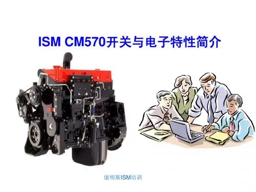
康明斯柴油发动机电子调速器及控制系统故障康明斯柴油发动机PT(G)型燃油系统中,使用EFC电子调速器。
调速器可以调成同步运行或调成有转速降的运行。
本文介绍的是发电机组或驱动发动机上的康明斯电子调速器EFC的原理、调整和故障诊断技术,对用户准确、快速地排除该类机型的故障具有重要作用。
1 工作原理该机自动化程度高,控制比较复杂。
调速器控制电路如图1所示。
电磁转速传感器3装在飞轮壳上。
通过飞轮齿圈感应发动机的转速。
执行器2装在PT泵内,改变执行器电流将使执行器的轴转动,从而改变发动机的转速和功率。
当CPU板J5第7脚的运行开关RUN闭合时,J1的1脚输出24V电压,PT泵电磁阀开关SWITCHED得电开启,EFC调速控制器4得电工作,使控制器2的轴转到最大供油位置。
同时,CPU板J1的第3脚输出起动信号到启动马达,使发动机启动。
发动机启动后,交流发电机的中点(N)电压(约12V)作为发动机已启动的信号,通过J2的第3脚输入CPU控制板,从而切断J1第3脚输出的信号,使启动机停止工作。
若一次启动不成功,停10s后将自动再次启动,若连续三次启动不成功,则停止启动,故障灯点亮。
发动机正常工作后,发动机的各种参数通过J3插座输入CPU板,由J4输出各种报警灯信号。
按J5的复位/灯检查按钮,可使CPU复位,同时进行各种报警灯测试,若所有报警灯都亮,说明整个报警控制系统工作正常。
发动机启动以后,EFC调速器4把来自电磁传感器的电讯号与现有的参考点(W2)相比较,输出差压电流信号,使执行器2的轴转动,控制进入喷嘴的燃油流量,从而改变发动机的转速和功率。
当发动机在W2调定的某一转速下稳定工作时,调速过程如下:负载↑↓→(转速传感器3)发动机转速↓↑→EFC调速器4输出电流↑↓→执行器2供油量↑↓→发动机转速↓↑→使发动机转速稳定在某一定值工作。
1.CPU控制板2.EFC油门执行器3.电磁转速传感器4.EFC电子调速器W1.怠速调整电位器W2.运行转速调整电位器W3.增益调整电位器W4.转速降调整电位器,J2-3.交流发电机中点电压(N)输入J2-7.机油压力传感器输入J2-8.水温传感器输入J3-2.油压低传感器输入J3-3.水温高预警传感器输入J3-4.油压低预警传感器输入J3-5.水温高传感器输入J4-12.油压低预警灯输出J4-11.水温高预警灯输出J4-10.油压低报警灯输出J4-9 水温高报警灯输出J4-8.超速报警灯输出J5-11.复位/灯检查按钮输入J5-7.运行按钮输入J5-4.接机油压力表J5-3.接水温表图1 控制电路原理图2 系统调整EFC调速控制器的面板上装有四个电位器,W1为怠速调整电位器(IDLE SPD),W2为运行转速调整电位器(RUN SPD),W3为增益调整电位器(GAIN),W4为转速降调整电位器(DROOP),这些电位器供系统调整时用。
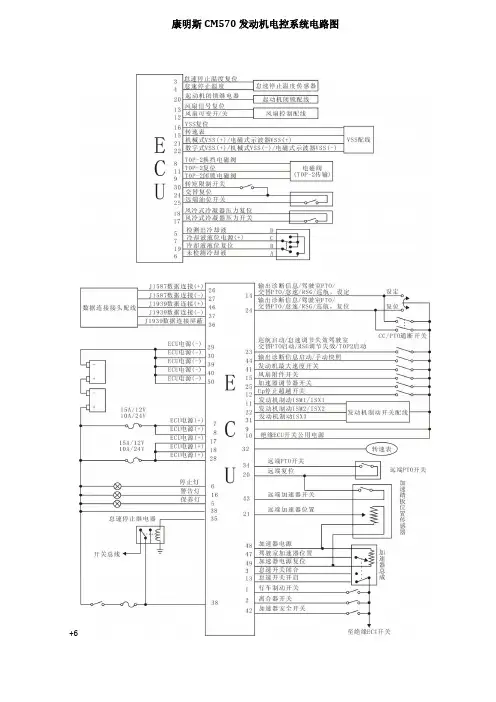
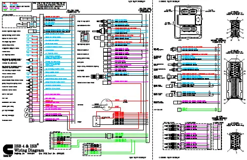
电路图
电路图略图
(1/2)
PTO加速踏板位置传感器
怠速传感器
加速踏板位置传感器1
加速踏板位置传感器2
大气压传感器
进气温度/MAF传感器
DPD差压传感器
过滤器入口
排气温度传感器
催化剂入口排气温度传感器
车速传感器或者EHCU
DPD开关
冷冻机开关
离合器开关
排气制动开关
预热开关
空压机继电器空调压力开关
冷凝器风扇继电器
空调单元空调开关
驻车/空档开关
驻车制动开关
PTO开关
发动机油位开关
转速记录表
排气制动电磁阀
起动机继电器
起动机切断继电器
预热塞
预热继电器
机油压力开关
发动机故障警报灯
排气制动显示灯
预热显示灯
DPD显示灯(橙色)
油压警报灯
壳体GND(接地)
降压电阻器
起动机开关(ON)
起动机开关(起动)
主继电器
钥匙开关
蓄电池
仪表
ECM
(2/2)
曲轴位置传感器
增压传感器进气节气门位置传感器发动机冷却液温度传感器
燃油温度传感器
EGR电机
EGR位置传感器
凸轮轴位置传感器
共轨压力传感器
防盗控制单元
(ICU)
进气节气门电机
喷油器驱动信号1(第1汽缸)
喷油器驱动信号3(第4汽缸)
喷油器驱动信号2(第3汽缸)
喷油器驱动信号4(第2汽缸)
吸入控制阀门(SCV)
排气节气门电磁阀
ECM
端子排列
81针式接头(J14)
40 针式接头(E12)
ECM 接线图。