康明斯工业柴油发动机电控特性-培训资料
- 格式:pdf
- 大小:1.24 MB
- 文档页数:68

•柴油机电控技术概述•传感器与执行器•电控燃油喷射系统目录•电控点火与爆震控制系统•进气与排气控制系统•故障诊断与排除方法01柴油机电控技术概述电控技术发展背景能源危机与环境保护随着全球能源危机和环境保护意识的提高,柴油机作为一种高效、清洁的动力源,其电控技术的发展成为必然趋势。
燃油喷射技术的演变从传统的机械式燃油喷射系统到现代的电控燃油喷射系统,柴油机的燃油喷射技术不断升级,为电控技术的发展奠定了基础。
排放法规的日益严格随着全球排放法规的日益严格,柴油机电控技术对于降低排放、提高燃油经济性和动力性具有重要作用。
1 2 3传感器控制单元(ECU)执行器柴油机电控系统组成电控技术原理通过传感器实时监测发动机运行状态,将信号传递给控制单元(ECU),ECU根据预设程序对执行器进行控制,从而实现对发动机的精确控制。
通过电控系统对发动机的精确控制,可以实现燃油喷射量、喷射正时等参数的精确调节,提高发动机的燃烧效率。
电控系统可以根据不同的发动机工况和驾驶需求进行灵活调整,实现发动机性能的最优化。
通过电控技术对发动机的精确控制,可以降低废气中的有害物质排放,满足日益严格的排放法规要求。
电控技术可以实现发动机的燃油经济性最优化,降低燃油消耗和运营成本。
精确控制降低排放提高燃油经济性灵活性高电控技术原理及特点02传感器与执行器温度传感器压力传感器位置传感器空气流量传感器根据ECU 的控制信号,精确控制燃油喷射量、喷射时间和喷射方式,实现燃油在发动机内的有效燃烧。
喷油器点火线圈怠速控制阀EGR 阀根据ECU 的控制信号,产生高压电火花,点燃可燃混合气,推动发动机正常运转。
通过改变怠速旁通空气道的截面积,调节怠速时的进气量,实现怠速稳定控制。
根据ECU 的控制信号,调节废气再循环量,降低NOx 排放。
传感器与执行器匹配关系传感器为执行器提供控制信号执行器根据传感器信号进行相应动作传感器与执行器协同工作实现发动机性能优化03电控燃油喷射系统燃油喷射系统组成及工作原理组成工作原理喷油器类型及特点喷油器主要分为轴针式、孔式、片阀式等类型。


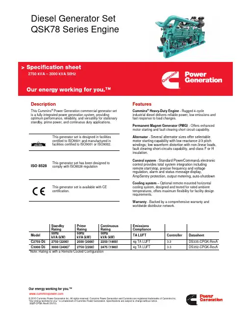


-;HA?DIBasic technical dataNumber of cylinders.. ... ... ... ... ... ... ... ... ... ... ... ... ... ... ... ... .12 Cylinder arrangement ... ... ... ... ... ... ... ... ... ... ... ... ... ... 60° Vee Cycle. ... ... ... ... ... ... ... ... ... ... ... ..4 stroke, compression ignition Induction system... ... ... ... ... ... ... ... ... ... ... ... ... ...Turbocharged Compression ratio. ... ... ... ... ... ... ... ... ... ... ... ... ..13,6:1 nominal Bore... ... ... ... ... ... ... ... ... ... ... ... ... ... ... ... ... ... ... ... ... 160 mm Stroke ... ... ... ... ... ... ... ... ... ... ... ... ... ... ... ... ... ... ... ... 190 mm Cubic capacity... ... ... ... ... ... ... ... ... ... ... ... ... ... ... ..45.842 litres Direction of rotation... ... ... ... ...Anti-clockwise viewed on flywheel Firing order ... ... ... ... ... ... ...1A,6B,5A,2B,3A,4B,6A,1B,2A,5B.4A,3B Cylinder 1 furthest from flywheelCylinders designated ‘A’ are on the left side of the engine when viewed from the front (opposite end to flywheel)Total weight Electrounit (engine only)4012TAG1A/2A(dry).. ... ... ... ... ... ... ... ... ... ... ... ... ... ... 4400 kg 4012TAG1A/2A(wet) ... ... ... ... ... ... ... ... ... ... ... ... ... ... 4604 kg Overall dimensions ... ... ... ... ... ... ... ... ... ... ... ...Height 2118 mm .. ... ... ... ... ... ... ... ... ... ... ... ... ... ... ... ... ... ... ..Length 2731 mm .. ... ... ... ... ... ... ... ... ... ... ... ... ... ... ... ... ... ... ....Width 1723 mm Moment of inertia.. ... ... ... ... ... ... ... ... ... ... ... .Engine 9.73 kgm2 .. ... ... ... ... ... ... ... ... ... ... ... ... ... ... ... ... ... ..Flywheel 9.57 kgm2 Cyclic irregularity for engine/flywheel (Prime power):4012TAG1A ... 1500 rev/min ... ... ... ... ... ... ... ... ... ... ... ... 1,714 4012TAG2A ... 1500 rev/min ... ... ... ... ... ... ... ... ... ... ... ... 1,669RatingsSteady state speed stability at constant load. ... ... ... ... ...± 0,25% Electrical ratings are based on average alternator efficiency and are for guidance only (0,8 power factor being used). Operating pointEngine speed. ... ... ... ... ... ... ... ... ... ... ... ... ... ... ...1500 rev/min Static injection timing.. ... ... ... ... ... ... ... See engine number plate Cooling water exit temperature.. ... ... ... ... ... ... ... ... ... ... .<98 °C Fuel dataTo conform to BS2869 class A1, A2.PerformanceSound pressure level 1500 rev/min ... ... ... ... ... ... ...106/112 dBA Note:All data based on operation to ISO 3046/1, BS 5514 and DIN 6271 standard reference conditions.Test conditionsAir temperature... ... ... ... ... ... ... ... ... ... ... ... ... ... ... ... ... ...25 °C Barometric pressure... ... ... ... ... ... ... ... ... ... ... ... ... ... ...100 kPa Relative humidity ... ... ... ... ... ... ... ... ... ... ... ... ... ... ... ... (30)Air inlet restriction at maximum power (nominal)... ... ... ... 2,5 kPa Exhaust back pressure (nominal)... ... ... ... ... ... ... ... ... ... 3,0 kPa4000 Series 4012TAG1A 4012TAG2AGeneral installation 4012TAG1ADesignation Units50Hz 1500 rev/min60Hz 1800 rev/min ContinuousBaseloadPrimePowerStandbyMaximumContinuousBaseloadPrimePowerStandbyMaximumGross engine power kWb94211781292---Fan power kWm42---Net engine power kWm90011361250---BMEP gross bar1620,522,5---Combustion air flow m3/min7695105---Exhaust gas temperature max (after turbo)°C435460470---Exhaust gas flow max (after turbo)m3/min257---Boost pressure ratio-2,73,223,53---Mechanical efficiency%899192---Overall thermal efficiency%424342---Friction power and pumping losses kWm120---Mean piston speed m/s9,5---Engine coolant flow (min)l/s17---Typical Genset Electrical Output 0,8 pf 25 °C (100 kPa)kVA108013631500---kWe86410911200---Assumed alternator efficiency%96---Diesel Engine - ElectrounitGeneral installation 4012TAG2ANote:Not to be used for CHP design purposes. (Indicative figures only). Consult Perkins Engines Co. Ltd. Assumes complete combustion.Continuous Baseload rating Power available for continuous full load operation. Prime Power rating is available for unlimited hours per year with a variable load of which the average engine load factor is 80% of the published prime power rating, incorporation of a 10% overload for 1 hour in every 12 hours of operation which is permitted. Standby Power rating is for the supply of emergency power at variable load for the duration of the non-availability of the mains power supply. NO OVERLOAD capacity is available at this rating. Engines must not be allowed to have facilities for parallel operation with the mains supply. This rating should be applied only when reliable mains power is available. Should this not be the case then refer to Prime Power rating. A standby rated engine should be sized for an average load factor of 80% based on published standby rating for 500 operating hours per year. Standby ratings should never be applied except in true emergency power failure conditions.DesignationUnits 50Hz 1500 rev/min60Hz 1800 rev/minContinuous BaseloadPrime Power Standby Maximum Continuous BaseloadPrime Power Standby MaximumGross engine power kWb 103712961422---Fan power kWm 42---Net engine power kWm 99512541380---BMEP gross bar 18,122,624,8---Combustion air flowm 3/min 83,6106110---Exhaust gas temperature max (after turbo)°C 442472483---Exhaust gas flow max (after turbo)m 3/min 285---Boost pressure ratio -2,83,533,84---Mechanical efficiency %889292---Overall thermal efficiency%424241---Friction power and pumping losses kWm 120---Mean piston speed m/s 9,5---Engine coolant flowl/s 17---Typical Genset Electrical Output 0,8 pf 25 °C (100 kPa)kVA 119415051656---kWe 95512041325---Assumed alternator efficiency%96---Energy balanceNote:Not to be used for CHP design purposes. (Indicative figures only). Consult Perkins Engines Co Ltd. Assumes complete combustion. 4012TAG1A4012TAG2A Units1500 rev/min1800 rev/min ContinuousBaseloadPrimePowerStandbyMaximumContinuousBaseloadPrimePowerStandbyMaximumEnergy in fuel kWt223827703117---Energy in power output (gross) kWb94211781292---Energy to cooling fan kWm424242---Energy in power output (net)kWm90011361250---Energy to exhaust kWt680760924---Energy to coolant and oil kWt353434465---Energy to radiation kWt4495100---Energy to charge coolers kWt219303336---Units1500 rev/min1800 rev/min ContinuousBaseloadPrimePowerStandbyMaximumContinuousBaseloadPrimePowerStandbyMaximumEnergy in fuel kWt244430783477---Energy in power output (gross) kWb103712961422---Energy to cooling fan kWm424242---Energy in power output (net)kWm99512541380---Energy to exhaust kWt7508771013---Energy to coolant and oil kWt372464511---Energy to radiation kWt4995108---Energy to charge coolers kWt236346423---Cooling systemRecommended coolant: 50% inhibited ethylene glycol or 50% inhibited propylene glycol and 50% clean fresh water. For combined heat and power systems and where there is no likelihood of ambient temperatures below 10 °C then clean ‘soft’ water may be used, treated with 1% by volume of Perkins inhibitor in the cooling system. The inhibitor is available in bottles under Perkins Part No. 21825 735.Nominal jacket water pressure in crankcase. ... ... ... ... ... .1,7 bar The following is a guide based on ambient air conditions of 52 °C on a Perkins supplied radiator.Total coolant capacity:Electrounit (engine only) ... ... ... ... ... ... ... ... ... ... ... ... ... 73 litres ElectropaK (engine/radiator) . ... ... ... ... ... ... ... ... ... ... ..235 litres Pressure cap setting.. ... ... ... ... ... ... ... ... ... ... ... ... ... ...0,69 bar Fan. ... ... ... ... ... ... ... ... ... ... ... ... ... ... ...Incorporated in radiator Diameter ... ... ... ... ... ... ... ... ... ... ... ... ... ... ... 1524 mm pusher) Ambient cooling clearance (open ElectropaK Prime power) based on air temperature at fan 3 °C above ambient.4012TAG1A4012TAG2ACoolant pump speed andmethod of drive.. ... ... ... ... ... ... ... ... ... ... ... 1,4 x e rev/min gear Maximum static pressure head on pumpabove engine crank centre line.. ... ... ... ... ... ... ... ... ... ... ... ..7 m Maximum external permissible restrictionto coolant pump flow.. ... ... ... ... ... ... ... ... ... ... ... ... ... ... .20 kPa Thermostat operating range... ... ... ... ... ... ... ... ... ... ... ..71-85 °C Shutdown switch setting ... ... ... ... ... ... ... ... ... ... ... 101 °C rising Coolant immersion heater capacity ... ... ... ... ... ... ... ... ..4 kW x 2 *4012TAG2A **4012TAG1A Lubrication systemRecommended lubricating oil to conform with the specification of API CG4 15W/40 .Lubricating oil capacity:Sump maximum.. ... ... ... ... ... ... ... ... ... ... ... ... ... ... ... 159 litres Sump minimum... ... ... ... ... ... ... ... ... ... ... ... ... ... ... ... 136 litres Lubricating oil temperature maximum to bearings.. ... ... ... 105 °C Lubricating oil pressure:at 80 °C temperature to bearing gallery (minimum) ... ... 0,34 MPa 4012TAG1A4012TAG2A*Typical after 250 hoursSump drain plug tapping size.. ... ... ... ... ... ... ... ... ... ... ... ... ..G1 Oil pump speed and method of drive..1,4 x e rev/min, gear driven Oil pump flow 1500 rev/min. ... ... ... ... ... ... ... ... ... ...6,0 litres/sec Shutdown switch setting.. ... ... ... ... ... ... ... ... ... ...1,93 bar falling Normal operating anglesFore and aft. ... ... ... ... ... ... ... ... ... ... ... ... ... ... ... ... ... ... ... ...5°Side tilt ... ... ... ... ... ... ... ... ... ... ... ... ... ... ... ... ... ... ... ... (10)Maximum additional restriction (duct allowance) to cooling airflow (Prime power) and resultant minimum airflowAmbient clearance 50% glycol Duct allowancemm H20Min airflowm3/minrev/min rev/min rev/min 150018001500180015001800 52 °C52 °20-1872-Maximum additional restriction (duct allowance) to cooling airflow (Prime power) and resultant minimum airflowAmbient clearance 50% glycol Duct allowancemm H20Min airflowm3/minrev/min rev/min rev/min 150018001500180015001800 52 °C52 °20-1872-Jacket cooling water data Units1500rev/min1800rev/minCoolant flow 4012TAG1A/2A l/s17,0-Coolant exit temperature (max)°C98-Coolant entry temperature (min)°C70-Coolant entry temperature (max) *°C85-Coolant entry temperature (max)**°C88-Oil consumptionPrime PowerUnits1500rev/min1800rev/min After running-in*g/kWhr0,50-Oil flow rate from pump I/s6,0-Oil consumptionPrime PowerUnits1500rev/min1800rev/min After running-in*g/kWhr0,51-Oil flow rate from pump I/s6,0-Fuel systemRecommended fuel... ..To conform to BS2869 1998 Class A1, A2 Type of injection system ... ... ... ... ... ... ... ... ... ... ..Direct injection Fuel injection pump... ... ... ... ... ... ... ... ... .Combined unit injector Fuel injector... ... ... ... ... ... ... ... ... ... ... ... .Combined unit injector Fuel injector opening pressure.. ... ... ... ... ... ... ... ... ... ... .234 bar Fuel lift pump. ... ... ... ... ... ... ... ... ... ... ... ... ... .Tuthill TCH 1-089 Delivery/hour at 1500 rev/min... ... ... ... ... ... ... ... ... ... .1020 litres Heat retained in fuel to tank . ... ... ... ... ... ... ... ... ... ... ... ..9,5 kW Temperature of fuel at lift pump to be less than ... ... ... ... ... 58 °C Fuel lift pump pressure.. ... ... ... ... ... ... ... ... ... ... ... ... ... ..3,0 bar Fuel lift pump maximum suction head... ... ... ... ... ... ... ... ... 2,5 m Fuel lift pump maximum pressure head (see Installation Manual) Fuel filter spacing.. ... ... ... ... ... ... ... ... ... ... ... ... ... ..10 microns) Governor type... ... ... ... ... ... ... ... ... ... ... ... ... ... ... ... .Electronic Torque at the governor output shaft.. ... ... ... ... ... ... ... 1,631 kgm Static injection timing ... ... ... ... ... ... ... .See engine number plate Tolerance on fuel consumption. ... ... ... ... ... .To ISO 8528-1 1993 4012TAG1A4012TAG2A Induction systemMaximum air intake restriction of engine:Clean filter.. ... ... ... ... ... ... ... ... ... ... ... ... ... ... ... ... 127 mm H20 Dirty filter ... ... ... ... ... ... ... ... ... ... ... ... ... ... ... ... ... 380 mm H20 Air filter type... ... ... ... ... ... ... ... ... ... ... ... ... ...4998-00-00 MF&T Exhaust systemMaximum back pressure for total system.Exhaust outlet flange size.. ... ... ... ... ... ... .2 x 254 mm (table ‘D’) For recommended pipe sizes, refer to the Installation Manual. Electrical systemType... ... ... ... ... ... ... ... ... ... ... ... ... ... ... ... ... ...Insulated return Alternator ... ... ... ... ... ... ... ... ... ... 24 volts with integral regulator Alternator output. ... ... ...40 amps at a stabilised output 28 volts at20 °C ambient Starter motor.. ... ... ... ... ... ... ... ... ... ... ... ... ... ... ... ... .. 24 volts Starter motor power ... ... ... ... ... ... ... ... ... ... ... ... ... ... ...16,4 kW Number of teeth on flywheel... ... ... ... ... ... ... ... ... ... ... ... ... ..156 Number of teeth on starter motor... ... ... ... ... ... ... ... ... ... ... (12)Minimum cranking speed at (0 °C). ... ... ... ... ... ... ... .120 rev/min Pull-in current of each starter motor solenoid... ... ... ... ... ... ... ... ... ... ... ... ... ... ... ... ... ... .30 amps at 24 volts Hold-in current of each starter motor solenoid... ... ... ... ... ... ... ... ... ... ... ... ... ... ... ... ... ... ...9 amps at 24 volts Engine stop solenoid.. ... ... ... ... ... ... ... ... ... ... ... ... ... ...24 volts Pull-in current of stop solenoid... ... ... ... ... ... .60 amps at 24 volts Hold-in current of stop solenoid.. ... ... ... ... ... 1,1 amps at 24 voltsFuel consumption (gross)Designation g/kWh Litres/hr rev/min1500180015001800 At Standby Max power rating203-309-At Prime Power rating199-276-At Continuous Baseload rating197-218-At 75% of Prime Power rating195-203-At 50% of Prime Power rating194-134-At 25% of Prime power rating207-72-Fuel consumption (gross)Designation g/kWh Litres/hr rev/min1500180015001800 At Standby Max power rating206-345-At Prime Power rating201-306-At Continuous Baseload rating197-240-At 75% of Prime Power rating197-225-At 50% of Prime Power rating195-149-At 25% of Prime power rating207-79-Designation Units1500rev/min1800rev/min 4012TAG1A mmH20949-4012TAG2A mmH20612-Engine mountingPosition of centre of gravity (wet engine) forward from rearface of crankcase .. ... ... ... ... ... ... ... ... ... ... ... ... ... ... ...771 mm Engine vertical centre line above crankshaft centre line ... .38 mm Maximum additional load applied to flywheel due to all rotating components ... ... ... ... ... ... ... ... ... ... ... ... ... ... ... ... ... ... .850 kgStarting requirementsNotes:l Battery capacity is defined by the 20 hour rate at 0 °C.lThe oil specification should be for the minimum ambient temperature as the oil will not be warmed by the immersion heater.lBreakaway current is dependent on battery capacity available. Cables should be capable of handling the transient current which may be up to double the steady cranking current.TemperaturerangeRange Down to 0 °C(32 °F)Oil:Starter:Battery:Max breakaway current:Cranking current:Aids:Starter cable size:Maximum length:API CG4 15W/402 x 24V4 x 12 volts x 286 Ah 1600 amps 810 ampsNot necessary 120 mm 26mGA DrawingLoad acceptance (cold)4012TAG1A1500 rev/min4012TAG2A1500 rev/minAbove complies with requirements of Classifications 3 & 4 of ISO 8528-12 and G2 operating limits stated in ISO 8528-5.The above figures were obtained under test conditions as follows:Engine block temperature.. ... ... ... ... ... ..45 °C Alternator efficiency ... ... ... ... ... ... ... ... ... 96%Minimum ambient temperature.. ... ... ... ..10 °C Isochronous GoverningUnder Frequency Roll Off (UFRO) set to 1 Hz below rated frequency Typical alternator inertia. ... ... ... ... ... .50 Kgm 2All tests were conducted using an engine which was installed and serviced to Perkins Engines Company Limited recommendations.Initial load applicationwhen engine reaches rated speed(15 seconds max after engine starts to crank)2nd Load applicationImmediately after engine has recovered to rated speed(5 seconds after initial load application)Prime power%Load kWm/kWe Nett Transient frequency deviation%Frequency recovery time secondsPrime power%Load kWm/kWe Nett Transient frequency deviation%Frequency recovery time seconds63715/686< -10537422/405< -105Initial load applicationwhen engine reaches rated speed(15 seconds max after engine starts to crank)2nd Load applicationImmediately after engine has recovered to rated speed(5 seconds after initial load application)Prime power%Load kWm/kWe Nett Transient frequency deviation%Frequency recovery time secondsPrime power%Load kWm/kWe Nett Transient frequency deviation%Frequency recovery time seconds57715/686< -10543539/518< -105Noise levelsThe figures for total noise levels are typical for an engine running at Prime Power rating in a semi-reverberant environment and measured at a distance of one metre from the periphery of the engine.Octave analysisThe following histograms show an octave band analysis at the position of the maximum noise level.Total noise levelSound pressure level re: -20 x 10-6 paSpeed 1500 rev/min......Ambient noise level 84 dBA.Octave analysis performed at the position of maximum noise.4012TAG1A4012TAG2APOSITION 11500 rev/min 106 - dBA1800 rev/min ------- dBA1500 rev/min 106 - dBA1800 rev/min ------- dBAPOSITION 21500 rev/min 108 - dBA 1800 rev/min ------- dBA 1500 rev/min 108 - dBA 1800 rev/min ------- dBA POSITION 3 1500 rev/min 111 - dBA 1800 rev/min ------- dBA 1500 rev/min 111 - dBA 1800 rev/min ------- dBA POSITION 4 1500 rev/min 111 - dBA 1800 rev/min ------- dBA 1500 rev/min 111 - dBA 1800 rev/min ------- dBA 4012TAG1A 4012TAG2A 4012TAG1A 4012TAG2A 4012TAG1A 4012TAG2A4012TAG1A4012TAG2A POSITION 71500 rev/min 108 - dBA 1800 rev/min ------- dBA 1500 rev/min 108 - dBA 1800 rev/min ------- dBA POSITION 6 1500 rev/min 112 - dBA 1800 rev/min ------- dBA 1500 rev/min 112 - dBA 1800 rev/min ------- dBA POSITION 5 1500 rev/min 112 - dBA 1800 rev/min ------- dBA 1500 rev/min 112 - dBA 1800 rev/min ------- dBA 4012TAG14012TAG24012TAG14012TAG24012TAG1A4012TAG2AFR4012TAG1A4012TAG2AThe information given on technical data sheets are for standard ratings only. For ratings other than shown contact Perkins Engines Company Limited, Stafford.Notes-;HA?DI All information in the document is substantially correct at the time of printing but may be subsequently altered by the company.Distributed by 4000 Series4012TAG1A 4012TAG2A P u bl i c a t i o n N o . T S L 4253, I s s u e 3, J a n u a r y 2003. P r i n t e d i n E n g l a n d . © P e r k i n s E n g i n e s C o m p a n y L i m i t e d .Perkins Engines Company Limited Stafford ST16 3UB United Kingdom Telephone +44 (0)1785 223141Fax +44 (0)1785 。
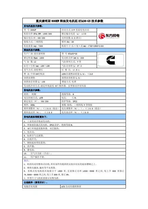
康明斯柴油发电机组技术参数
1.发电机组类型:康明斯柴油发电机组可以根据不同的应用场景和需求,分为蓄电池启动型和自动启动型两种类型。
蓄电池启动型适用于应急备用电源或辅助电源,而自动启动型则适用于自动化程度较高的场景。
2.功率范围:康明斯柴油发电机组的功率范围广泛,可根据用户需求选择不同的机型。
通常的功率范围在10千瓦至3000千瓦之间,以满足不同规模的用电需求。
3.输出电压:康明斯柴油发电机组的输出电压可根据用户需要设定。
常见的输出电压有220V、380V和400V等,可以适应不同国家和地区的电网标准。
4.频率:康明斯柴油发电机组的频率通常为50Hz或60Hz。
50Hz的发电机组适用于大部分国家和地区,而60Hz的发电机组主要应用于美国、加拿大等地。
5.柴油机型号:康明斯柴油发电机组采用的柴油机型号有很多种,其中较常见的有康明斯N系列和康明斯K系列。
这些柴油机具有低噪音、低排放、高效率等特点,可可靠地输出稳定的功率。
6.燃油消耗率:康明斯柴油发电机组的燃油消耗率较低,能够提供长时间的稳定供电。
一般情况下,燃油消耗率在190-215克/千瓦时之间。
8.控制系统:康明斯柴油发电机组配备了先进的数字控制系统,能够实现对发电机组的智能监测和远程操作。
这些控制系统具有用户友好的界面,可以实时监测和调整发电机组的运行状态。
以上是康明斯柴油发电机组的一些常见技术参数。
通过了解这些参数,用户可以选择适合自己需求的发电机组,并合理利用发电机组提供可靠稳
定的电力供应。
z赛瓦特发电机组的设计、生产和测试完全符合GB/T2820-97的国家标准,广泛应用于工业、矿山、建筑、通讯等领域,甚至在极为恶劣的环境下,也能提供非常可靠的电力;z 赛瓦特独创设计的内置多级减振系统,能有效的消除机组运行时的振动,使控制系统及电气元件受到更好的保护;z 配备重庆康明斯发动机,技术先进,性能可靠,高燃烧效率及低燃油消耗,持续运行时间长,具有超长的工作寿命,可在各种环境下稳定运行,且保养和维护方便;z 配备STAMFORD 发电机,承受瞬间加载时电压、频率恢复迅速,非线性负载下的波形畸变率极小,附加PMG 后起动电动机的能力更强;z 标准配制PCRC230控制系统,具有高性价比和应用灵活的控制保护功能,能适应各种气候条件。
直观的LCD 数字显示发电机组各项参数,使用户在操作和维护过程中更加简便。
康明斯N 系列柴油发动机,中美合资重庆康明斯公司生产。
额定转速1500RPM ,四冲程、直列、风扇水箱闭式冷却,符合ISO3046标准。
z 高可靠性,低排放,起动性能好 z 24V 直流电启动马达 z 柴油机驱动充电发电机 z 康明斯专利PT 油泵,电子调速 z 废气涡轮增压z 燃油、机油、空气滤清器 z SAE 标准飞轮壳世界一流品牌斯坦福同步交流发电机,英资无锡新时代公司生产。
符合GB755, BS5000, VDE0530, IEC34-1, CSA22.2, AS2359标准。
z 无刷自励发电机系统,在各种情况下均可提供可靠励磁;z 标准的2/3节距绕组,有效抑制过多的中线电流; z 绝缘等级:H ,防护等级:IP23;z 稳态电压调整率:≤±1.0%; z 电话干扰:THF < 2%, TIF < 50;z 与其他品牌发电机相比,斯坦福发电机效率最高。
赛瓦特标准配置PCRC230控制系统,采用丹麦DEIF 品牌GC-1F 控制模块,为基于微处理技术、包含所有功能的柴油发电机保护控制器。