美国环保局 EPA 试验 方法 8290
- 格式:pdf
- 大小:612.69 KB
- 文档页数:71
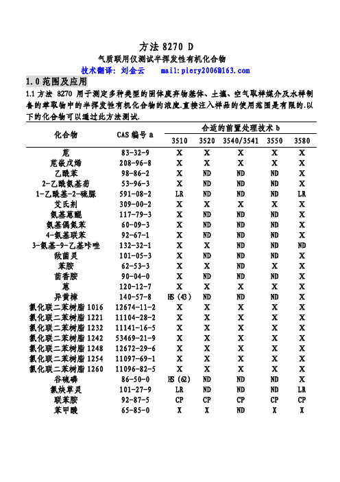
方法8270 D气质联用仪测试半挥发性有机化合物技术翻译:刘金云 mail:piery2006@1.0范围及应用1.1方法 8270 用于测定多种类型的固体废弃物基体、土壤、空气取样媒介及水样制备的萃取物中的半挥发性有机化合物的浓度.直接注入样品的使用范围是有限的.以下的化合物可以通过此方法测试.合适的前置处理技术b 化合物 CAS编号a3510 35203540/3541 35503580 苊 83-32-9 Ⅹ Ⅹ Ⅹ Ⅹ Ⅹ 苊嵌戊烯 208-96-8 Ⅹ Ⅹ Ⅹ Ⅹ Ⅹ乙酰苯 98-86-2 Ⅹ ND ND ND Ⅹ 2-乙酰氨基芴 53-96-3 Ⅹ ND ND ND Ⅹ 1-乙酰基-2-硫脲 591-08-2 LR ND ND ND LR 艾氏剂 309-00-2 Ⅹ Ⅹ Ⅹ Ⅹ Ⅹ 氨基蒽醌 117-79-3 Ⅹ ND ND ND Ⅹ 氨基偶氮苯 60-09-3 Ⅹ ND ND ND Ⅹ 4-氨基联苯 92-67-1 Ⅹ ND ND ND Ⅹ 3-氨基-9-乙基咔唑 132-32-1 Ⅹ Ⅹ ND ND ND 敌菌灵 101-05-3 Ⅹ ND ND ND Ⅹ苯胺 62-53-3 Ⅹ Ⅹ ND Ⅹ Ⅹ茴香胺 90-04-0 Ⅹ ND ND ND Ⅹ 蒽 120-12-7 Ⅹ Ⅹ Ⅹ Ⅹ Ⅹ 异黄樟 140-57-8 H S(43)ND ND ND Ⅹ 氯化联二苯树脂101612674-11-2 Ⅹ Ⅹ Ⅹ Ⅹ Ⅹ 氯化联二苯树脂122111104-28-2 Ⅹ Ⅹ Ⅹ Ⅹ Ⅹ 氯化联二苯树脂123211141-16-5 Ⅹ Ⅹ Ⅹ Ⅹ Ⅹ 氯化联二苯树脂124253469-21-9 Ⅹ Ⅹ Ⅹ Ⅹ Ⅹ 氯化联二苯树脂124812672-29-6 Ⅹ Ⅹ Ⅹ Ⅹ Ⅹ 氯化联二苯树脂125411097-69-1 Ⅹ Ⅹ Ⅹ Ⅹ Ⅹ 氯化联二苯树脂126011096-82-5 Ⅹ Ⅹ Ⅹ Ⅹ Ⅹ 谷硫磷 86-50-0 H S(62)ND ND ND Ⅹ 氯炔草灵 101-27-9 LR ND ND ND LR联苯胺 92-87-5 CP CP CP CP CP苯甲酸 65-85-0 X X ND X X合适的前置处理技术 b 化合物 CAS编号a3510 35203540/3541 35503580 苯并蒽 56-55-3 Ⅹ Ⅹ Ⅹ Ⅹ Ⅹ 苯并(b)荧蒽 205-99-2 Ⅹ Ⅹ Ⅹ Ⅹ Ⅹ 苯并(k)荧蒽 207-08-9 Ⅹ Ⅹ Ⅹ Ⅹ Ⅹ 苯并(g,h,i)茈 191-24-2 Ⅹ Ⅹ Ⅹ Ⅹ Ⅹ 苯并(a)芘 50-32-8 Ⅹ Ⅹ Ⅹ Ⅹ Ⅹ p-苯醌 106-51-4 OE ND ND ND X苯甲醇 100-51-6 Ⅹ Ⅹ ND Ⅹ Ⅹ α-六氯化苯 319-84-6 Ⅹ Ⅹ Ⅹ Ⅹ Ⅹ β-六氯化苯 319-85-7 Ⅹ Ⅹ Ⅹ Ⅹ Ⅹ δ-六氯化苯 319-86-8 Ⅹ Ⅹ Ⅹ Ⅹ Ⅹ γ-六氯化苯(林旦)58-89-9 Ⅹ Ⅹ Ⅹ Ⅹ Ⅹ 双(2-氯乙氧基)甲烷111-91-1 Ⅹ Ⅹ Ⅹ Ⅹ Ⅹ 双(2-氯乙基)醚 111-44-4 Ⅹ Ⅹ Ⅹ Ⅹ Ⅹ 双(2-氯异丙基)醚108-60-1 Ⅹ Ⅹ Ⅹ Ⅹ Ⅹ 双(2-氯乙基己基)邻苯二甲酸酯117-81-7 Ⅹ Ⅹ Ⅹ Ⅹ Ⅹ 4-溴苯基苯醚 101-55-3 Ⅹ Ⅹ Ⅹ Ⅹ Ⅹ 溴苯腈 1689-84-5 Ⅹ ND ND ND Ⅹ 邻苯二甲酸丁基·苄基酯85-68-7 Ⅹ Ⅹ Ⅹ Ⅹ Ⅹ 敌菌丹 2425-06-1 H S(55)ND ND ND Ⅹ克菌丹 133-06-2 H S(40)ND ND ND Ⅹ甲萘威 63-25-2 Ⅹ ND ND ND Ⅹ呋喃丹 1563-66-2 Ⅹ ND ND ND Ⅹ二硫磷 786-19-6 Ⅹ ND ND ND Ⅹ 氯丹(NOS) 57-74-9 Ⅹ Ⅹ Ⅹ Ⅹ Ⅹ 毒虫威 470-90-6 Ⅹ ND ND ND Ⅹ 4-氯苯胺 106-47-8 Ⅹ ND ND ND Ⅹ 乙酯杀螨醇 510-15-6 Ⅹ ND ND ND Ⅹ 对氯邻氨基甲苯 95-79-4 Ⅹ ND ND ND Ⅹ 4-氯-3-甲苯酚 59-50-7 Ⅹ Ⅹ Ⅹ Ⅹ Ⅹ 3-(氯甲苯)吡啶盐6959-48-4 Ⅹ ND ND ND Ⅹ 酸盐1-氯代萘 90-13-1 Ⅹ Ⅹ Ⅹ Ⅹ Ⅹ 2-氯代萘 91-58-7 Ⅹ Ⅹ Ⅹ Ⅹ Ⅹ 2-氯苯酚 95-57-8 Ⅹ Ⅹ Ⅹ Ⅹ Ⅹ 4-氯-1,2-苯二胺 95-83-0 Ⅹ Ⅹ ND ND ND 4-氯-1,3-苯二胺 5131-60-2 Ⅹ Ⅹ ND ND ND 4-氯苯基苯醚 7005-72-3 Ⅹ Ⅹ Ⅹ Ⅹ Ⅹ合适的前置处理技术 b 化合物 CAS编号a3510 35203540/3541 35503580 1,2-苯并菲 218-01-9 Ⅹ Ⅹ Ⅹ Ⅹ Ⅹ 香豆磷 56-72-4 Ⅹ ND ND ND Ⅹ 甲酚定 120-71-8 Ⅹ ND ND ND Ⅹ 丁烯磷 7700-17-6 Ⅹ ND ND ND Ⅹ 2-环己烯-4,6-二硝基-苯酚131-89-5 Ⅹ ND ND ND LR 4,4-DDD 72-54-8 Ⅹ Ⅹ Ⅹ Ⅹ Ⅹ 4,4-DDE 72-55-9 Ⅹ Ⅹ Ⅹ Ⅹ Ⅹ 4,4-DDT 50-29-3 Ⅹ Ⅹ Ⅹ Ⅹ X O-异内吸磷 298-03-3 H S(68)ND ND ND Ⅹ S-异内吸磷 126-75-0 Ⅹ ND ND ND Ⅹ 燕麦敌(顺式或反式)2303-16-4 Ⅹ ND ND ND Ⅹ 2,4-二氨基甲苯 95-80-7 D C,0E(42)ND ND ND Ⅹ 二苯并(a,j)吖啶 224-42-0 ⅩND ND NDⅩ二苯并(a,h)蒽 53-70-3 ⅩⅩⅩⅩⅩ二苯并呋喃 132-64-9 ⅩⅩNDⅩⅩ二苯并(a,e)芘 192-65-4 ND ND ND NDⅩ1,2-溴-3-氯丙烷 96-12-8 ⅩⅩND ND ND 苯二甲酸-n-二丁酯 84-74-2 ⅩⅩⅩⅩⅩ二氯萘醌 117-80-6 OE ND ND NDⅩ1,2-二氯代苯 95-50-1 ⅩⅩⅩⅩⅩ1,3-二氯代苯 541-73-1 ⅩⅩⅩⅩⅩ1,4-二氯代苯 106-46-7 ⅩⅩⅩⅩⅩ3,3-二氯联苯胺 91-94-1 ⅩⅩⅩⅩⅩ2,4-二氯苯酚 120-83-2 ⅩⅩⅩⅩⅩ2,6-二氯苯酚 87-65-0 ⅩND ND NDⅩ敌敌畏 62-73-7 ⅩND ND NDⅩ百治磷 141-66-2 ⅩND ND NDⅩ狄氏剂 60-57-1 ⅩⅩⅩⅩⅩ酞酸二乙酯 84-66-2 ⅩⅩⅩⅩⅩ乙烯雌酚 56-53-1 AW,ND ND NDⅩ0S(67)硫酸二乙酯 64-67-5 LR ND ND ND LR 乐果 60-51-5 H E,ND ND NDⅩH S(31)3,3`-二甲氨基联苯氨 119-90-4 ⅩND ND ND LR 二甲氨基偶氮苯 60-11-7 ⅩND ND ND X 7,12甲基苯并(a)蒽 57-97-6 C P(45)ND ND ND CP合适的前置处理技术b 化合物 CAS编号a351035203540/3541 35503580 3,3`-二甲基联苯胺 119-93-7 Ⅹ ND ND ND Ⅹ α,α-二甲基苯乙胺 122-09-8 ND ND ND ND Ⅹ 2,4-二甲苯酚 105-67-9 Ⅹ Ⅹ Ⅹ Ⅹ Ⅹ 苯二甲酸二甲酯 131-11-3 Ⅹ Ⅹ Ⅹ Ⅹ Ⅹ 1,2-二硝基苯 528-29-0 Ⅹ ND ND ND X 1,3-二硝基苯 99-65-0 Ⅹ ND ND ND Ⅹ 1,4二硝基苯 100-25-4 H E(14)ND ND ND Ⅹ 4,6-二硝基-2-甲酚 534-52-1 Ⅹ Ⅹ Ⅹ Ⅹ Ⅹ 2,4-二硝基苯酚 51-28-5 Ⅹ Ⅹ Ⅹ Ⅹ Ⅹ 2,4-二硝基甲苯 121-14-2 Ⅹ Ⅹ Ⅹ Ⅹ Ⅹ 2,6二硝基甲苯 606-20-2 Ⅹ Ⅹ Ⅹ Ⅹ Ⅹ 敌螨普 39300-45-3 CP,HS ND ND ND CP(28)二硝丁酚 88-85-7 Ⅹ ND ND ND Ⅹ 二苯胺 122-39-4 Ⅹ Ⅹ X Ⅹ Ⅹ 苯妥英 57-41-0 X ND ND ND Ⅹ 1,2-二苯肼 122-66-7 Ⅹ Ⅹ Ⅹ Ⅹ Ⅹ 磷酸-n-二辛酯 117-84-0 Ⅹ Ⅹ Ⅹ Ⅹ Ⅹ 乙拌磷 298-04-4 X ND ND ND Ⅹ 硫丹Ⅰ 959-98-8 Ⅹ Ⅹ Ⅹ Ⅹ Ⅹ 硫丹Ⅱ 33213-65-9 Ⅹ Ⅹ Ⅹ Ⅹ Ⅹ 硫酸硫丹 1031-07-8 Ⅹ Ⅹ Ⅹ Ⅹ Ⅹ 异狄氏剂 72-20-8 Ⅹ Ⅹ Ⅹ Ⅹ Ⅹ 异狄氏剂醛 7421-93-4 Ⅹ Ⅹ Ⅹ Ⅹ Ⅹ 异狄氏剂酮 53494-70-5 Ⅹ X ND X Ⅹ 苯硫磷 2104-64-5 Ⅹ ND ND ND Ⅹ 乙硫磷 563-12-2 Ⅹ ND ND ND Ⅹ 氨基甲酸乙酯 51-79-6 D C(28)ND ND ND Ⅹ 乙基甲磺酸 62-50-0 Ⅹ ND ND ND Ⅹ 氨磺磷 52-85-7 Ⅹ ND ND ND Ⅹ 丰索磷 115-90-2 Ⅹ ND ND ND Ⅹ 倍硫磷 55-38-9 Ⅹ ND ND ND Ⅹ 氯氟灵 33245-39-5 Ⅹ ND ND ND Ⅹ荧蒽 206-44-0 Ⅹ Ⅹ Ⅹ Ⅹ Ⅹ芴 86-73-7 Ⅹ Ⅹ Ⅹ Ⅹ Ⅹ 2-氟(代)联苯 321-60-8 Ⅹ Ⅹ Ⅹ Ⅹ Ⅹ 2-氟(代)苯酚 367-12-4 Ⅹ Ⅹ Ⅹ Ⅹ Ⅹ合适的前置处理技术b 化合物 CAS编号a351035203540/3541 35503580 七氯化茚 76-44-8 X X X X X 七氯环氧化物 1024-57-3 X X X X X 六氯化苯 118-74-1 X X X X X 六氯丁二烯 87-68-3 X X X X X 六氯环戊二烯 77-47-4 X X X X X 六氯乙烷 67-72-1 X X X X X六氯酚 70-30-4 A W,ND ND ND CPC P(62)六氯丙烯 1888-71-7 X ND ND ND X 六甲基磷酸三酰胺 680-31-9 X ND ND ND X 对苯二酚 123-31-9 ND ND ND ND X 茚并(1,2,3-cd)芘 193-39-5 X X X X X 异艾氏剂 465-73-6 X ND ND ND X 异佛尔酮 78-59-1 X X X X X 异黄樟素 120-58-1 D C(46)ND ND ND X十氯酮 143-50-0 X ND ND ND X溴苯磷 21609-90-5 X ND ND ND X 马拉硫磷 121-75-5 HS(5)ND ND ND X 顺丁烯二酸酐 108-31-6 HE ND ND ND X 炔雌醇甲醚 72-33-3 X ND ND ND X 噻吩甲吡胺 91-80-5 X ND ND ND X 甲氧氯 72-43-5 X ND ND ND X 甲基胆蒽 56-49-5 X ND ND ND X 4,4`-亚甲基双 101-14-4 O E,O S ND ND ND LR (-2氯苯胺) (0)4,4`-亚甲基双 101-61-1 X X ND ND ND (N,N-二甲基-苯胺)甲基甲磺酸 66-27-3 X ND ND ND X 2-甲基萘 91-57-6 X X ND X X 甲基对硫磷 298-00-0 X ND ND ND X 2-甲苯酚 95-48-7 X ND ND ND X 3-甲苯酚 108-39-4 X ND ND ND X 4-甲苯酚 106-44-5 X ND ND ND X速灭磷 7786-34-7 X ND ND ND X兹克威 315-18-4 H E,H S ND ND ND X(68)灭蚁灵 2385-85-5 X ND ND ND X久效磷 6923-22-4 HE ND ND ND X合适的前置处理技术b 化合物 CAS编号a351035203540/3541 35503580 二溴磷 300-76-5 Ⅹ ND ND ND Ⅹ 萘 91-20-3 Ⅹ Ⅹ Ⅹ Ⅹ Ⅹ萘醌 130-15-4 Ⅹ ND ND ND Ⅹ1-萘胺 134-32-7 O S(44)ND ND ND Ⅹ2-萘胺 91-59-8 Ⅹ ND ND ND Ⅹ烟碱 54-11-5 D E(67)ND ND ND X 5-硝基苊 602-87-9 Ⅹ ND ND ND Ⅹ 2-硝基苯胺 88-74-4 Ⅹ Ⅹ ND Ⅹ Ⅹ 3-硝基苯胺 99-09-2 Ⅹ Ⅹ ND Ⅹ Ⅹ 4-硝基苯胺 100-01-6 Ⅹ Ⅹ ND Ⅹ Ⅹ 2-甲氧基-5-硝基苯胺 99-59-2 Ⅹ ND ND ND Ⅹ 硝基苯 98-95-3 Ⅹ Ⅹ Ⅹ Ⅹ Ⅹ 4-硝基联苯 92-93-3 Ⅹ ND ND ND Ⅹ 除草醚 1836-75-5 Ⅹ ND ND ND Ⅹ 2-硝基苯酚 88-75-5 Ⅹ Ⅹ Ⅹ Ⅹ Ⅹ 4-硝基苯酚 100-02-7 Ⅹ Ⅹ Ⅹ Ⅹ Ⅹ 5-硝基-2-甲苯胺 99-55-8 Ⅹ X ND ND Ⅹ 硝基硅啉-1-氧化物 56-57-5 Ⅹ ND ND ND Ⅹ N-亚硝基二丁胺 924-16-3 X ND ND ND Ⅹ N-亚硝基二乙胺 55-18-5 X ND ND ND Ⅹ N-亚硝基二甲胺 62-75-9 Ⅹ X X X Ⅹ N-亚硝基甲基乙胺 10595-95-6 Ⅹ ND ND ND Ⅹ N-亚硝基二苯胺 86-30-6 Ⅹ X X X Ⅹ N-亚硝基二丙胺 621-64-7 Ⅹ Ⅹ Ⅹ Ⅹ Ⅹ 亚硝基吗啉 59-89-2 ND ND ND ND Ⅹ N-亚硝基呱啶 100-75-4 Ⅹ ND ND ND Ⅹ 亚硝基吡咯烷 930-55-2 Ⅹ ND ND ND Ⅹ 八甲基焦磷酰胺 152-16-9 LR ND ND ND LR 4,4`-羟基二苯胺 101-80-4 Ⅹ ND ND ND Ⅹ 对硫磷 56-38-2 Ⅹ X ND ND Ⅹ五氯苯 608-93-5 X ND ND ND X 五氯硝基苯 82-68-8 Ⅹ ND ND ND Ⅹ 五氯苯酚 87-86-5 Ⅹ Ⅹ Ⅹ Ⅹ Ⅹ 非那西丁 62-44-2 Ⅹ ND ND NDⅩ 菲 85-01-8 Ⅹ Ⅹ X X X 菲巴比妥 50-06-6 Ⅹ ND ND ND Ⅹ 苯酚 108-95-2 D C(28)Ⅹ Ⅹ Ⅹ Ⅹ合适的前置处理技术b 化合物 CAS编号a3510 35203540/3541 35503580 1,4-苯二胺 106-50-3 Ⅹ ND ND ND Ⅹ 甲拌磷 298-02-2 Ⅹ Ⅹ Ⅹ Ⅹ Ⅹ 伏杀硫磷 2310-17-0 HS(65)ND ND ND Ⅹ 亚胺硫磷 732-11-6 HS(15)ND ND ND Ⅹ 磷胺 13171-21-6 H E(63)ND ND ND Ⅹ酞酐 85-44-9 C P,H E(1)ND ND ND CP 2-皮考啉(2-甲基吡啶)109-06-8 Ⅹ X ND ND ND 胡椒基亚砜 120-62-7 Ⅹ ND ND ND Ⅹ 拿草特 23950-58-5 Ⅹ ND ND ND Ⅹ 丙硫氧密啶 51-52-5 LR ND ND ND LR 芘 129-00-0 Ⅹ X X X Ⅹ 间苯二酚 108-46-3 DC,OE ND ND ND Ⅹ(10)Ⅹ 黄樟素 94-59-7 Ⅹ ND ND ND Ⅹ 番木鳖碱 57-24-9 AW,0S ND ND ND Ⅹ(55)菜草特 95-06-7 Ⅹ ND ND ND Ⅹ叔丁磷 13071-79-9 Ⅹ ND ND ND Ⅹ 1,2,4,5-四氯苯 95-94-3 X ND ND ND Ⅹ 2,3,4,6-四氯苯酚 58-90-2 X ND ND ND Ⅹ 杀虫畏 961-11-5 Ⅹ ND ND ND Ⅹ 四乙基二硫代焦磷酸3689-24-5 Ⅹ X ND ND ND 焦磷酸四乙酸酯 107-49-3 Ⅹ ND ND ND Ⅹ 硫磷嗪 297-97-2 Ⅹ ND ND ND Ⅹ 苯硫酚(硫酚) 108-98-5 X ND ND ND Ⅹ 甲苯二异氰酸酯 584-84-9 HE(6)ND ND ND Ⅹ 邻甲苯胺 95-53-4 Ⅹ ND ND ND Ⅹ毒杀芬 8001-35-2 X X X X X 1,2,3-三氯苯 120-82-1 Ⅹ X X X Ⅹ 2,4,5-三氯苯酚 95-95-4 Ⅹ X ND X Ⅹ 2,4,6-三氯苯酚 88-06-2 X X X X X 氟乐灵 1582-09-8 Ⅹ ND ND ND Ⅹ 2,4,5-三甲基苯胺 137-17-7 Ⅹ ND ND ND Ⅹ 磷酸三甲酯 512-56-1 H E(60)ND ND NDⅩ 1,3,5-三硝基苯 99-35-4 Ⅹ ND ND ND X 磷酸三(2,3-二溴丙基酯)126-72-7 Ⅹ ND ND ND LR合适的前置处理技术b 化合物 CAS编号a351035203540/3541 35503580 磷酸邻三甲苯酯 78-32-0 Ⅹ ND ND ND Ⅹ O,O,O-三乙基代磷酸酯126-68-1 Ⅹ ND ND ND Ⅹ a: CAS-化学文摘服务处.b: 其它可以接受的前置处理方法参见第1.2节.分析物目录要点:AW=在萃取和储存时,吸附到玻璃器皿内壁上.CP=不可重复的色谱性能DC=不理想的分布系数(括号中的数字为回收率百分数)HE=萃取时的水解作用在酸性或碱性条件的催化下加快(括号中的数字为回收率百分数).HS=储存时的水解作用(括号中的数字为稳定性百分率)LR=较低的回应ND=没有测试到OE=萃取时,在碱性条件的催化作用下氧化作用加快(括号中的数字为回收率百分数).OS=储存时被氧化(括号中的数字为稳定性百分率).X=通过此种技术回收率大于70%.1.2除了在以上的分析物目录中列出的样品制备方法外,方法3535描述的是一个固相萃取程序,可应用于从TCLP浸出液中(表16与表17中包含性能数据)提取半挥发性物质.方法3542描述的是气体中的半挥发性有机化合物的样品制备程序,气体是通过方法0010(表11中含有代用物的性能数据)取样的.方法3545描述的是利用溶剂从固体中自动萃取半挥发性物质的装置(表12包含有性能数据).方法3561描述的是从固体中萃取多环芳香烃类(PAHs)的超临界流体装置(见表格13,14,15中的性能数据). 1.3对于能溶解于二氯甲烷的中性、酸性和碱性有机化合物,且它们能够被洗脱,无需衍生化便可从气相色谱熔融二氧化硅毛细管柱(柱上涂有少量的极性硅酮)显现尖锐的峰,大多数这样的有机化合物可用方法8270来定量测试.这些化合物包括:多环芳香烃类(PAHs)、氯化烃类、农药、邻苯二甲酸酯类、有机磷酸酯类、亚硝胺类、卤代醚类、醛类、醚类、酮类、苯胺类、吡啶类、喹啉类、芳香族硝基化合物、酚类(包括硝基酚类)。

US EPA 8270E方法8270E气相色谱法/质谱分析法(气质联用仪)测试半挥发性有机化合物SEMIVOLATILE ORGANIC COMPOUNDS BY GAS CHROMATOGRAPHY/MASSSPECTROMETRY第6版2017年2月目录1.0 范围与应用 (3)2.0方法概述 (14)3.0定义 (14)4.0干扰 (14)5.0安全性 (14)6.0仪器及材料 (14)7.0试剂和标准溶液 (16)8.0样品收集、保存和储存 (18)9.0 质量控制 (18)10.0校准和标准化 (21)11.0程序 (21)12.0数据分析和计算 (30)13.0方法性能 (30)14.0污染防治 (32)15.0废弃物管理 (32)16.0 参考文献 (33)17.0表格、图表、流程图以及验证数据 (34)方法8270E气相色谱法/质谱分析法(气质联用仪)测试半挥发性有机化合物SW-846并非一本分析培训手册。
因此,本文所述方法步骤基于一个假设,即这些方法步骤由至少在化学分析基本原理和特定学科技术使用方面进行过正式培训的分析人员来进行。
除用于分析特定的方法参数外,其他情况下,SW-846方法仅作指导,包括分析步骤或技术操作的基本资料。
各实验室可依据这些资料编制自己实验室的具体标准操作程序(SOP),用于一般用途或具体项目中。
本方法中包括的性能数据仅具有指导性,不作为/不可作为实验室认证的质量控制验收标准。
1.0 范围与应用1.1本方法用于测定由多种类型的固体废弃物基质、土壤、空气取样媒介及水样所制备的萃取物中的半挥发性有机化合物的浓度。
直接注入样品的使用范围有限。
以下的分析物可以通过本方法测试:合适的制备工艺b 化合物CAS No a3510 3520 3540/3541 3545 3550 3580苊83-32-9 ✓✓✓✓✓✓蔡嵌戊烯208-96-8✓✓✓✓✓✓乙酰苯98-86-2✓✓✓✓✓✓2-乙酰氨基芴53-96-3 ✓✓-✓✓-1-乙酰基-2-硫脲591-08-2 *----*艾氏剂309-00-2✓✓✓-✓✓2-氨基蒽醌117-79-3✓----✓氨基偶氮苯60-09-3✓----✓4-氨基联苯92-67-1 ✓*✓*--*✓3-氨基-9-乙基咔唑132-32-1 ✓✓----敌菌灵101-05-3✓----✓苯胺62-53-3 ✓*✓*✓**✓*✓邻茴香胺90-04-0 ✓----✓蒽120-12-7 ✓✓✓✓✓✓杀螨酯140-57-8 ✓*✓*--✓-氯化三联苯1016 12674-11-2 ✓✓✓-✓✓氯化三联苯1221 11104-28-2 ✓✓✓-✓✓氯化三联苯1232 11141-16-5 ✓✓✓-✓✓化合物CAS No a3510 3520 3540/3541 3545 3550 3580 氯化三联苯1242 53469-21-9 ✓✓✓-✓✓氯化三联苯1248 12672-29-6 ✓✓✓-✓✓氯化三联苯1254 11097-69-1 ✓✓✓-✓✓氯化三联苯1260 阿特拉津11096-82-5✓1912-24-9✓*✓✓*✓✓*✓✓*-✓*✓✓-谷硫磷偶氮苯86-50-0*103-33-3✓*✓-----✓✓-燕麦灵苯甲醛101-27-9*100-52-7✓*-✓*-✓*-✓*-✓**-联苯胺92-87-5***✓***苯甲酸65-85-0*✓*✓**✓*✓*苯并(a)蒽56-55-3 ✓✓✓✓✓✓苯并(b)荧蒽205-99-2 ✓✓✓✓✓✓苯并(k)荧蒽207-08-9 ✓✓✓✓✓✓苯并(g,h,i)芘191-24-2✓✓✓✓✓✓苯并(a)芘苯并(e)芘50-32-8✓192-97-2✓✓-✓-✓-✓✓✓-对苯醌106-51-4 **---✓苯甲醇100-51-6 ✓*✓*✓*✓*✓*✓*α-六氯苯319-84-6 ✓*✓*✓-✓✓β-六氯苯319-85-7 ✓✓✓-✓✓δ-六氯苯319-86-8✓✓✓-✓✓γ-六氯苯(林旦)58-89-9 ✓*✓*✓-✓✓双(2-氯乙氧基)甲烷111-91-1 ✓✓✓✓✓✓双(2-氯乙基)醚111-44-4 ✓✓✓✓✓✓双(2- 氯代-1-甲基乙基)醚c108-60-1 ✓✓✓-✓✓双(2-乙基己基)邻苯二甲酸酯117-81-7 ✓✓✓✓✓✓4-溴苯基苯醚101-55-3 ✓✓✓✓✓✓溴苯腈1689-84-5✓----✓邻苯二甲酸丁苄酯己内酰胺85-68-7✓105-60-2*✓*✓✓✓✓✓✓✓-敌菌丹2425-06-1 **---✓克菌丹133-06-2* *---✓化合物CAS No a3510 3520 3540/3541 3545 3550 3580西维因咔唑63-25-2✓86-74-8✓-✓-✓-✓-✓✓-虫螨威1563-66-2 ✓----✓三硫磷786-19-6✓----✓氯丹(NOS)57-74-9 ✓✓✓-✓✓毒虫畏470-90-6 ✓----✓4-氯苯胺106-47-8 ✓✓✓✓✓✓乙酯杀螨醇510-15-6✓✓-✓✓✓5-氯-2-甲基苯胺95-79-4✓----✓4-氯-3-甲苯酚59-50-7✓✓✓✓✓✓3-(氯甲基)吡啶氢氯化物6959-48-4✓----✓1-氯萘90-13-1✓✓✓-✓ ✓ 2-氯萘91-58-7✓✓✓✓✓✓2-氯苯酚4-氯苯基苯基醚95-57-8✓7005-72-3✓✓✓✓✓✓✓✓✓✓✓4-氯代-1,2-苯二胺95-83-0 ✓✓----4-氯代-1,3-苯二胺5131-60-2✓✓----屈218-01-9✓✓✓✓✓✓蝇毒磷56-72-4 ✓----✓对甲酚定120-71-8 ✓----✓丁烯磷7700-17-6 ✓----✓2-环已烯-4,6-二硝基苯酚131-89-5✓-----4,4'-DDD 72-54-8✓✓✓-✓✓4,4'-DDE 72-55-9✓✓✓-✓✓4,4'-DDT 50-29-3 ✓✓✓-✓✓异内吸磷-O 298-03-3 **---✓异内吸磷-S 126-75-0 **---✓燕麦敌(顺式或反式)2303-16-4✓✓-✓✓✓2,4-二氨基甲苯95-80-7 **---✓二苯并(a,j)吖啶224-42-0✓---✓†✓二苯并(a,h)蒽53-70-3 ✓✓✓✓✓✓二苯并呋喃132-64-9 ✓✓✓✓✓✓化合物CAS No a3510 3520 3540/3541 3545 3550 3580 二苯并(a, e)芘192-65-4✓---✓✓1,2-二溴-3-氯丙烷96-12-8✓✓----邻苯二甲酸二正丁酯84-74-2 ✓✓✓✓✓✓二氯萘醌117-80-6**---✓1,2-二氯苯95-50-1 ✓*✓*✓*✓*✓*✓1,3-二氯苯541-73-1 ✓*✓*✓*✓*✓* ✓* 1,4-二氯苯106-46-7 ✓*✓*✓*✓*✓*✓3,3'-二氯联苯胺91-94-1 ✓*✓*✓*✓*✓*✓* 2,4-二氯苯酚120-83-2✓✓✓✓✓✓2,6-二氯苯酚87-65-0✓✓✓✓✓✓敌敌畏62-73-7 ✓----✓百治磷141-66-2✓----✓狄氏剂60-57-1✓✓✓-✓✓酞酸二乙酯84-66-2✓✓✓✓✓✓己烯雌酚64-67-5*----*硫酸二乙酯56-53-1**---✓乐果60-51-5 ✓*✓*--✓*✓3,3'-二甲氧基联苯胺邻苯二甲酸二甲酯119-90-4✓131-11-3✓-✓-✓-✓-✓*✓二甲氨基偶氮苯60-11-7✓✓-✓✓✓7,12-二甲基苯并[a]蒽57-97-6 ✓*✓*-✓*✓** 3,3'-二甲基联苯胺119-93-7 **-**✓α,α-二甲基苯乙胺122-09-8-----✓2,4-二甲苯酚105-67-9 ✓✓✓✓✓✓1,2-二硝基苯528-29-0✓✓--✓✓1,3-二硝基苯99-65-0 ✓✓-✓✓✓1,4-二硝基苯100-25-4 ✓*---✓✓4,6-二硝基-2-甲酚534-52-1 ✓*✓*✓*✓*✓*✓* 2,4-二硝基酚51-28-5 ✓*✓*✓*✓*✓*✓* 2,4-二硝甲苯121-14-2 ✓✓✓✓✓✓2,6-二硝甲苯606-20-2 ✓✓✓✓✓✓敌螨普39300-45-3 **---*邻苯二甲酸二辛酯117-84-0✓✓✓✓✓✓化合物CAS No a3510 3520 3540/3541 3545 3550 3580 地乐酚88-85-7 ✓✓✓-✓✓1,4-二氧六环123-91-1 *✓****-二苯胺122-39-4✓✓✓-✓✓苯妥英57-41-0 ✓----✓1,2-二苯联胺122-66-7 ✓*✓*✓*✓*✓*✓*乙拌磷298-04-4 ✓✓--✓✓硫丹I 959-98-8 ✓*✓*✓-✓✓硫丹II 33213-65-9 ✓*,✓*✓-✓✓硫丹硫酸盐1031-07-8✓✓✓-✓✓异狄氏剂72-20-8 ✓*✓*✓-✓✓异狄氏剂醛7421-93-4 ✓✓✓-✓✓异狄氏剂酮53494-70-5✓✓--✓✓苯硫磷2104-64-5 ✓----✓乙硫磷563-12-2✓----✓氨基甲酸乙酯51-79-6*----✓甲基磺酸乙酯62-50-0✓✓-✓✓✓氨磺磷52-85-7 ✓*---*✓丰索磷115-90-2✓----✓倍硫磷55-38-9 ✓- - - - ✓ 氟消草33245-39-5 ✓----✓荧蒽206-44-0✓✓✓✓✓✓芴86-73-7✓✓✓✓✓✓七氯76-44-8 ✓✓✓-✓✓七氯环氧化物1024-57-3 ✓✓✓-✓✓六氯化苯118-74-1✓✓✓✓✓✓六氯丁二烯87-68-3✓✓✓✓✓✓六氯环戊二烯77-47-4 ✓**✓*✓*✓*✓*六氯乙烷67-72-1✓✓✓✓✓✓六氯酚70-30-4 ✓*----*六氯丙烯1888-71-7✓*✓✓✓✓六甲基磷酰胺680-31-9✓----✓对苯二酚123-31-9-----✓茚并(1,2,3-cd)芘193-39-5 ✓✓✓✓✓✓化合物 CAS No a 3510 3520 3540/3541 3545 3550 3580 异艾氏剂 465-73-6✓ ✓ - ✓ ✓ ✓ 异佛尔酮 78-59-1✓ ✓ ✓ ✓ ✓ ✓ 异黄樟素 120-58-1✓ ✓ - ✓ ✓ ✓ 聚氯酮 143-50-0✓* - - - ✓ ✓ 溴苯磷 马拉硫磷 顺丁烯二酸酐 炔雌醇甲醚 美沙吡林 甲氧滴滴涕 甲基磺酸甲酯 甲基对硫磷 3-甲基胆蒽4,4'-亚甲基双(2-氯苯胺) 4,4'-亚甲基双(N,N-二甲基-苯胺)21609-90-5✓ 121-75-5* 108-31-6* 72-33-3✓ 91-80-5* 72-43-5✓ 66-27-3✓* 298-00-0✓ 56-49-5 ✓101-14-4✓101-61-1✓ - * * - - - ✓* ✓ ✓ * ✓ - - - - - - - - - * - - - - - - - - - - - - - - - - - ✓ ✓* ✓ ✓ - - ✓ ✓ ✓ ✓ ✓ ✓ ✓ ✓ ✓ * - 1-甲基萘 90-12-0✓ ✓ ✓ ✓ ✓ - 2-甲基萘91-57-6✓ ✓ ✓ ✓ ✓ ✓ 2-甲基苯酚(邻甲酚) 95-48-7 ✓ ✓ ✓ ✓ ✓ ✓ 3-甲基苯酚(间甲酚) 108-39-4 ✓ ✓ ✓ ✓ ✓ ✓ 4-甲基苯酚(对甲酚) 106-44-5 ✓ ✓ ✓ ✓ ✓ ✓ 速灭磷 7786-34-7 ✓ - - - - ✓ 兹克威 315-18-4 * * - - - ✓ 灭蚁灵 2385-85-5 ✓ - - - - ✓ 久效磷 6923-22-4 * * - - - ✓ 二溴磷 300-76-5✓ - - - - ✓ 萘 91-20-3 ✓ ✓ ✓ ✓ ✓ ✓ 1,4-萘醌 130-15-4 ✓* ✓* - ✓* ✓* ✓ 1-萘胺 134-32-7 ✓* ✓* - - * ✓ 2-萘胺 91-59-8 ✓* ✓* - - * ✓ 烟碱 54-11-5 * - - - - ✓ 5-硝基苊602-87-9✓----✓化合物CAS No a3510 3520 3540/3541 3545 3550 3580 2-硝基苯胺88-74-4 ✓*✓*✓*✓*✓*✓*3-硝基苯胺99-09-2 ✓*✓*✓*✓*✓*✓*4-硝基苯胺100-01-6 ✓*✓--✓*✓5-硝基-邻甲氧基苯胺99-59-2✓----✓硝基苯98-95-3✓✓✓✓✓✓4-硝基联苯92-93-3 ✓----✓除草醚1836-75-5 ✓----✓2-硝基苯酚88-75-5 ✓✓✓✓✓✓4-硝基苯酚100-02-7*✓*✓*✓*✓*✓*4-硝基喹啉-1-氧化物56-57-5 ✓✓-✓✓✓N-亚硝基二丁胺924-16-3✓✓✓-✓✓N-亚硝基二乙胺55-18-5✓✓✓✓✓✓N-亚硝基二甲胺62-75-9*✓*✓*✓*✓*✓*N-亚硝基二苯胺86-30-6 ✓*✓*✓*✓*✓*✓*N-亚硝基正丙胺621-64-7 ✓✓✓✓✓✓N-亚硝基甲基乙胺10595-95-6✓✓✓✓✓✓N-亚硝基吗啉59-89-2 ✓✓-✓✓✓N-亚硝基哌啶100-75-4 ✓✓✓-✓✓N-亚硝基吡咯烷930-55-2✓✓✓✓✓✓5-硝基-o-甲苯胺盐酸盐99-55-8 ✓✓-✓✓✓八甲基焦磷酰胺152-16-9 *----*4,4'-氧联二苯胺101-80-4✓----✓对硫磷56-38-2 ✓✓--✓✓五氯苯608-93-5✓✓✓✓✓✓五氯硝基苯82-68-8✓✓-✓✓✓五氯苯酚87-86-5 ✓*✓*✓*✓*✓*✓*苝198-55-0✓----✓非那西丁62-44-2✓✓-✓✓✓菲85-01-8✓✓✓✓✓✓苯巴比妥50-06-6 ✓----✓苯酚108-95-2 *✓*✓*✓*✓*✓* 1,4-苯二胺106-50-3 ✓--*-✓甲拌磷298-02-2 ✓✓--✓✓化合物CAS No a3510 3520 3540/3541 3545 3550 3580 伏杀硫磷2310-17-0 **---✓亚胺硫磷732-11-6 **---✓磷胺13171-21-6**---✓邻苯二甲酸酐85-44-9 **---*2-吡啶(2-甲基吡啶)109-06-8 ✓✓-✓✓-哌嗪基亚砜120-62-7 ✓----✓多氯联苯(NOS)1336-36-3------拿草特23950-58-5✓✓-✓✓✓丙基硫氧嘧啶51-52-5 *----*芘129-00-0 ✓✓✓✓✓✓吡啶110-86-1 *✓*✓**✓*-间苯二酚108-46-3***--✓黄樟油94-59-7✓✓-✓✓✓士的宁57-24-9* * * - - - 草克死95-94-3✓----✓特丁硫磷13071-79-9✓✓--- - 1,2,4,5-四氯苯95-94-3✓✓ ✓✓✓✓2,3,4,6-四氯苯酚58-90-2✓✓✓✓✓✓杀虫畏961-11-5✓----✓四乙基二硫代焦磷酸酯3689-24-5 ✓✓--✓-焦磷酸四乙酯107-49-3 ✓----✓硫酸嗪297-97-2 ✓✓--✓✓硫酚(苯硫酚) 108-98-5 ✓----✓2,4-甲苯二异氰酸酯584-84-9**---✓邻甲基苯胺95-53-4 ✓✓-✓*✓毒杀芬8001-35-2 ✓✓✓-✓✓1,2,4-三氯苯120-82-1✓✓✓✓✓✓2,4,5-三氯苯酚95-95-4✓✓✓✓✓✓2,4,6-三氯苯酚88-06-2 ✓✓✓✓✓✓O,O,O-三乙基硫代磷酸酯126-68-1 ✓✓--✓-氟乐灵(treflan)1582-09-8 ✓----✓磷酸三甲酯512-56-1**---✓合适的制备工艺b 化合物CAS No a3510 3520 3540/3541 3545 3550 35802,4,5-三甲基苯胺137-17-7✓----✓1,3,5 -三硝基苯(1,3,5-TNB))99-35-4 ✓✓-✓✓✓磷酸三(2,3二溴丙基)126-72-7✓----*三对甲苯磷酸酯78-32-0✓----✓a化学文摘服务登记号b其他可接受的制备方法见第1.2节。

CD-ROM 8091 - 1Revision 0December 1996METHOD 8091NITROAROMATICS AND CYCLIC KETONES BY GAS CHROMATOGRAPHY1.0SCOPE AND APPLICATION1.1Method 8091 is a gas chromatographic (GC) method used to determine the concentration of nitroaromatics and cyclic ketones. It describes wide-bore, open-tubular, capillary column gas chromatography procedures using either electron capture (ECD) or nitrogen-phosphorous (NPD)detectors. The following RCRA analytes can be determined by this method:CompoundCAS No.a 1,4-Dinitrobenzene 100-25-42,4-Dinitrotoluene 121-14-22,6-Dinitrotoluene 606-20-21,4-Naphthoquinone 130-15-4Nitrobenzene98-95-3Pentachloronitrobenzene82-68-8Chemical Abstract Service Registry Number.a1.2 The following non-RCRA analytes can also be determined by this method:CompoundCAS No.a Benefin 1861-40-1Butralin33629-47-91-Chloro-2,4-dinitrobenzene 97-00-71-Chloro-3,4-dinitrobenzene 610-40-21-Chloro-2-nitrobenzene 88-73-31-Chloro-4-nitrobenzene 100-00-52-Chloro-6-nitrotoluene 83-42-14-Chloro-2-nitrotoluene 89-59-84-Chloro-3-nitrotoluene 89-60-12,3-Dichloronitrobenzene 3209-22-12,4-Dichloronitrobenzene 611-06-33,5-Dichloronitrobenzene 618-62-23,4-Dichloronitrobenzene 99-54-72,5-Dichloronitrobenzene89-61-2Compound CAS No.aDinitramine29091-05-21,2-Dinitrobenzene528-29-01,3-Dinitrobenzene99-65-0Isopropalin33820-53-01,2-Naphthoquinone524-42-52-Nitrotoluene88-72-23-Nitrotoluene99-08-14-Nitrotoluene99-99-0Penoxalin (Pendimethalin)40487-42-1Profluralin26399-36-02,3,4,5-Tetrachloronitrobenzene879-39-02,3,5,6-Tetrachloronitrobenzene117-18-01,2,3-Trichloro-4-nitrobenzene17700-09-31,2,4-Trichloro-5-nitrobenzene89-69-02,4,6-Trichloronitrobenzene18708-70-8Trifluralin1582-09-81.3This method is restricted to use by, or under the supervision of, analysts experienced in the use of gas chromatographs and skilled in the interpretation of gas chromatograms. Each analyst must demonstrate the ability to generate acceptable results with this method.2.0SUMMARY OF METHOD2.1Method 8091 provides gas chromatographic conditions for the detection of ppb concentrations of nitroaromatics and cyclic ketones in water and soil or ppm concentrations in waste samples. Prior to use of this method, appropriate sample extraction techniques must be used for environmental samples (refer to Chapter Two and Method 3500). Both neat and diluted organic liquids (Method 3580) may be analyzed by direct injection. Analysis is accomplished by gas chromatography utilizing an instrument equipped with wide bore capillary columns and one or more electron capture detectors or nitrogen-phosphorus detectors (NPD).3.0INTERFERENCES3.1Refer to Method 3500, 3600, and 8000.3.2The electron capture detector responds to all electronegative compounds. Therefore, interferences are possible from other halogenated compounds, as well as phthalates and other oxygenated compounds such as organonitrogen, organosulfur, and organophosphorus compounds. Second column confirmation or GC/MS confirmation is necessary to ensure proper analyte identification unless previous characterization of the sample source will ensure proper identification.3.3Contamination by carryover can occur whenever high-concentration and low-concentration samples are sequentially analyzed. To reduce carryover, the syringe used for injection must be thoroughly rinsed between samples with solvent. Whenever a highly concentrated sample extract is encountered, it should be followed by the analysis of a solvent blank to check for CD-ROM8091 - 2Revision 0December 1996CD-ROM 8091 - 3Revision 0December 1996cross-contamination. Additional solvent blanks interspersed with the sample extracts should be considered whenever the analysis of a solvent blank indicates cross-contamination problems.3.4In certain cases some compounds coelute on either one or both columns. In these cases the compounds must be reported as coeluting. The mixture can be reanalyzed by GC/MS techniques if concentration permits (see Method 8270).3.4.1DB-5 column:2,4,6-trichloronitrobenzene/1,3-dinitrobenzene1-chloro-2,4-dinitrobenzene/1-chloro-3,4-dinitrobenzene/1,2,3-trichloro-4-nitrobenzene 3.4.2DB-1701 column:2,4-dichloronitrobenzene/4-chloro-3-nitrotoluene 2,4,6-trichloronitrobenzene/1,4-naphthoquinone1-chloro-2,4-dinitrobenzene/2,3,4,5-tetrachloronitrobenzene3.4.3In addition, on the DB-5 column, 2,5-dichloronitrobenzene is not well resolved from 4-chloro-3-nitrotoluene. Also, Trifluralin is not well resolved from Benefin. On the DB-1701 column, compound pairs that are not well resolved include 4-nitrotoluene/1-chloro-3-nitrobenzene and Trifluralin/Benefin.3.5Solvents, reagents, glassware, and other sample processing hardware may yield discrete artifacts and/or elevated baselines causing misinterpretation of gas chromatograms. All these materials must be demonstrated to be free from interferences under the conditions of the analysis,by analyzing reagent blanks.4.0APPARATUS AND MATERIALS4.1Gas chromatograph: An analytical system complete with a gas chromatograph suitable for on-column and split/splitless injection, and all accessories, including syringes, analytical columns,gases, electron capture detectors or nitrogen-phosphorus detectors. A GC equipped with a single GC column and detector or other configurations of column and detector is also acceptable. A data system for measuring peak areas and/or peak heights, and dual display of chromatograms is recommended.4.1.1Suggested GC Columns: Alternative columns may be used to provide the separation needed to resolve all target analytes listed in Sec. 1.1 of this method. Refer to Chapter One for additional information regarding column performance and QA requirements.4.1.1.1Column 1 - 30 m x 0.53 mm ID fused-silica open- tubular column,crosslinked and chemically bonded with 95 percent dimethyl and 5 percent diphenyl-polysiloxane (DB-5, RT -5, SPB-5, or equivalent), 0.83 µm or 1.5 µm film x thickness.4.1.1.2Column 2 - 30 m x 0.53 mm ID fused-silica open-tubular columncrosslinked and chemically bonded with 14 percent cyanopropylphenyl and 86 percent dimethyl-polysiloxane (DB-1701, RT -1701, or equivalent), 1.0 µm film thickness.xCD-ROM 8091 - 4Revision 0December 19964.1.2Splitter: If the splitter approach to dual column injection is chosen, following are three suggested splitters. An equivalent splitter is acceptable. See Sec. 7.5.1 for a caution on the use of splitters.4.1.2.1Splitter 1 - J&W Scientific press-fit Y-shaped glass 3-way union splitter(J&W Scientific, Catalog No. 705-0733).4.1.2.2Splitter 2 - Supelco 8-in glass injection tee, deactivated (Supelco,Catalog No. 2-3665M).4.1.2.3Splitter 3 - Restek Y-shaped fused-silica connector (Restek, Catalog No.20405).4.1.3Column rinsing kit (optional): Bonded-phase column rinse kit (J&W Scientific,Catalog No. 430-3000 or equivalent).4.2Microsyringes - 100 µL, 50 µL, 10 µL (Hamilton 701 N or equivalent), and 50 µL (Blunted,Hamilton 705SNR or equivalent).4.3Balances - Analytical, 0.0001 g, Top-loading, 0.01 g.4.4Volumetric flasks, Class A - 10 mL to 1000 mL.5.0REAGENTS5.1Reagent grade chemicals shall be used in all tests. Unless otherwise indicated, all reagents shall conform to the specifications of the Committee on Analytical Reagents of the American Chemical Society, where such specifications are available. Other grades may be used,provided it is first ascertained that the chemicals are of sufficiently high purity to permit their use without affecting the accuracy of the determinations.5.2Solvents 5.2.1Hexane, C H - Pesticide quality or equivalent.6145.2.2Acetone, CH COCH - Pesticide quality or equivalent.335.2.3Isooctane, (CH )CCH CH(CH ) - Pesticide quality or equivalent.332325.3Stock standard solutions (1000 mg/L): Can be prepared from pure standard materials or can be purchased as certified solutions.5.3.1Prepare stock standard solutions by accurately weighing about 0.0100 g of pure compound. Dissolve the compound in isooctane or hexane and dilute to volume in a 10 mL volumetric flask. (Isooctane is preferred because it is less volatile than hexane.) If compound purity is 96 percent or greater, the weight can be used without correction to calculate the concentration of the stock standard solution. Commercially prepared stock standard solutions can be used at any concentration if they are certified by the manufacturer or by an independent source.5.3.2For those compounds which are not adequately soluble in hexane or isooctane,dissolve the compound initially with a small volume of toluene, ethyl acetate or acetone and dilute to volume with isooctane or hexane.5.4Composite stock standard: Can be prepared from individual stock solutions. For composite stock standards containing less than 25 components, transfer exactly 1 mL of each individual stock solution at 1000 mg/L, add solvent, mix the solutions, and bring to volume in a 25 mL volumetric flask. For example, for a composite containing 20 individual standards, the resulting concentration of each component in the mixture, after the volume is adjusted to 25 mL, will be 40 mg/L. This composite solution can be further diluted to obtain the desired concentrations. For composite stock standards containing more than 25 components, use volumetric flasks of the appropriate volume (e.g., 50 mL, 100 mL).5.5Calibration standards: These should be prepared at a minimum of five concentrations by dilution of the composite stock standard with isooctane or hexane. The standard concentrations should correspond to the expected range of concentrations present in the field samples and should bracket the linear range of the detector.5.6Recommended internal standard: Prepare a solution of 1000 mg/L of hexachlorobenzene. For spiking, dilute this solution to 50 ng/µL. (This concentration may need to be more dilute depending on the detector chosen and its sensitivity. The internal standard response should be approximately 50 to 90% of full scale.) Use a spiking volume of 10.0 µL/mL of extract. The spiking concentration of the internal standards should be kept constant for all samples and calibration standards.5.7Recommended surrogate standard: Monitor the performance of the method using surrogate compounds. Surrogate standards are added to all samples, method blanks, matrix spikes, and calibration standards. Prepare a solution of 1000 mg/L of 1-chloro-3-nitrobenzene and dilute it to 10 ng/µL. (This concentration may need to be adjusted depending on the detector chosen and its sensitivity. The surrogate standard response should be approximately 100% of full scale.) Usea spiking volume of 100 µL for a 1 L aqueous sample.5.8Store the standard solutions (stock, composite, calibration, internal, and surrogate) at 4E C or cooler in polytetrafluoroethylene(PTFE)-sealed containers in the dark. All standard solutions must be replaced after six months or sooner if routine QC (Sec. 8.0) indicates a problem.6.0SAMPLE COLLECTION, PRESERVATION, AND HANDLING6.1See the introductory material to this chapter, Organic Analytes, Sec. 4.1.6.2Extracts must be stored in the dark at or below 4E C and analyzed within 40 days of extraction.7.0PROCEDURE7.1Extraction and Cleanup:7.1.1Refer to Chapter Two and Method 3500 for guidance on choosing the appropriateextraction procedure. In general, water samples are extracted at a pH between 5 to 9 with CD-ROM8091 - 5Revision 0December 1996methylene chloride, using either Method 3510 or 3520. Solid samples are extracted using any of the extraction methods for solids listed in Method 3500, as appropriate.7.1.2If necessary, the samples may be cleaned up using Method 3620 (Florisil) and/orMethod 3640 (Gel Permeation Chromatography). See Chapter Two, Sec. 2.0 and Method 3600 for general guidance on cleanup and method selection. Method 3660 is used for sulfur removal.7.1.3Prior to gas chromatographic analysis, the extraction solvent needs to beexchanged to hexane. The exchange is performed using the K-D procedures listed in each of the extraction methods. Any methylene chloride remaining in the extract will cause a very broad solvent peak.7.2Gas Chromatographic Conditions: Retention time information for each of the analytes is presented in Tables 1 and 3. The recommended GC operating conditions are provided in Tables 2 and 4. Figures 1, 2, and 3 illustrate typical chromatography of the method analytes for both columns when operated at the conditions specified.7.3Calibration:7.3.1Prepare calibration standards using the procedures in Sec. 5.0. Refer to Method8000, Sec. 7.0 for proper calibration procedures. The procedure for internal or external calibration may be used.7.3.2Refer to Method 8000, Sec. 7.0 for the establishment of retention time windows.7.4Gas chromatographic analysis:7.4.1Method 8000, Sec. 7.0 provides instructions on calibration, establishing retentiontime windows, the analysis sequence, appropriate dilutions, and identification criteria.7.4.2Automatic injections of 1 µL are recommended. Hand injections of no more than2 µL may be used if the analyst demonstrates quantitation precision less than or equal to 10percent relative standard deviation. The solvent flush technique may be used if the amount of solvent is kept at a minimum. If the internal standard calibration technique is used, add10 µL of the internal standard to each mL of sample extract prior to injection.7.4.3Tentative identification of an analyte occurs when a peak from a sample extractfalls within the absolute retention time window. Normally, confirmation is necessary.Confirmation techniques include analysis on a second column with dissimilar stationary phase, by GC/MS (full scan or SIM) or by using a different detector and getting comparable data. See Sec. 7.0 of Method 8000 on "Compound Identification" for further information.7.4.3.1If partially overlapping or coeluting peaks are present, install columnswith a dissimilar liquid phase or use a GC/MS technique. Interferences that preventanalyte identification and/or quantitation may possibly be removed by the cleanuptechniques mentioned above.7.4.4Record the volume injected to the nearest 0.05 µL and the resulting peak size inarea units or peak height. Using either the internal or the external calibration procedure (Method 8000), determine the quantity of each component peak in the sample chromatogram which corresponds to the compounds used for calibration purposes.CD-ROM8091 - 6Revision 0December 19967.4.4.1If the responses exceed the linear range of the system, dilute the extractand reanalyze. Peak height measurements are recommended, rather than peak areaintegration, when overlapping peaks may cause errors in area integration.7.4.4.2If the peak response is less than 2.5 times the baseline noise level, thevalidity of the quantitative result may be questionable. The analyst should consult withthe source of the sample to determine whether further concentration of the sample iswarranted.7.4.5Determine the concentration of each identified analyte using the calculationformulae in Sec. 7.0 of Method 8000.7.5Instrument Maintenance:7.5.1Injection of sample extracts from waste sites often leaves a high boiling residuein the injection port area, splitters when used, and the injection port end of the chromatographic column. This residue affects chromatography in many ways (i.e., peak tailing, retention time shifts, analyte degradation, etc.) and, therefore, instrument maintenance is very important. Residue buildup in a splitter may limit flow through one leg and therefore change the split ratios. If this occurs during an analytical run, the quantitative data may be incorrect.Proper cleanup techniques will minimize the problem and instrument QC will indicate when instrument maintenance is required.7.5.2Suggested chromatograph maintenance: Corrective measures may require anyone or more of the following remedial actions. Also see Sec. 7.0 in Method 8000 for additional guidance on corrective action for capillary columns and the injection port.7.5.2.1Splitter connections: For dual columns which are connected using apress-fit Y-shaped glass splitter or a Y-shaped fused-silica connector, clean anddeactivate the splitter or replace with a cleaned and deactivated splitter. Break off thefirst few inches (up to one foot) of the injection port side of the column. Remove thecolumns and solvent backflush according to the manufacturer's instructions. If theseprocedures fail to eliminate the degradation problem, it may be necessary to deactivatethe metal injector body and/or replace the columns.7.5.2.2Column rinsing: The column should be rinsed with several columnvolumes of an appropriate solvent. Both polar and nonpolar solvents are recommended.Depending on the nature of the sample residues expected, the first rinse might be water,followed by methanol and acetone; methylene chloride is a satisfactory final rinse and insome cases may be the only solvent required. The column should then be filled withmethylene chloride and allowed to remain flooded overnight to allow materials within thestationary phase to migrate into the solvent. The column is then flushed with freshmethylene chloride, drained, and dried at room temperature with a stream of ultrapurenitrogen passing through the column.8.0QUALITY CONTROL8.1Refer to Chapter One and Method 8000 for specific quality control (QC) procedures. Quality control procedures to ensure the proper operation of the various sample preparation and/or sample introduction techniques can be found in Methods 3500 and 5000. Each laboratory should CD-ROM8091 - 7Revision 0December 1996maintain a formal quality assurance program. The laboratory should also maintain records to document the quality of the data generated.8.2Quality control procedures necessary to evaluate the GC system operation are found in Method 8000, Sec. 7.0 and includes evaluation of retention time windows, calibration verification and chromatographic analysis of samples.8.3Initial Demonstration of Proficiency - Each laboratory must demonstrate initial proficiency with each sample preparation and determinative method combination it utilizes, by generating data of acceptable accuracy and precision for target analytes in a clean matrix. The laboratory must also repeat the following operations whenever new staff are trained or significant changes in instrumentation are made. See Method 8000, Sec. 8.0 for information on how to accomplish this demonstration.8.4Sample Quality Control for Preparation and Analysis - The laboratory must also have procedures for documenting the effect of the matrix on method performance (precision, accuracy, and detection limit). At a minimum, this includes the analysis of QC samples including a method blank, a matrix spike, a duplicate, and a laboratory control sample (LCS) in each analytical batch and the addition of surrogates to each field sample and QC sample.8.4.1Documenting the effect of the matrix should include the analysis of at least onematrix spike and one duplicate unspiked sample or one matrix spike/matrix spike duplicate pair.The decision on whether to prepare and analyze duplicate samples or a matrix spike/matrix spike duplicate must be based on a knowledge of the samples in the sample batch. If samples are expected to contain target analytes, then laboratories may use one matrix spike and a duplicate analysis of an unspiked field sample. If samples are not expected to contain target analytes, laboratories should use a matrix spike and matrix spike duplicate pair.8.4.2 A Laboratory Control Sample (LCS) should be included with each analytical batch.The LCS consists of an aliquot of a clean (control) matrix similar to the sample matrix and of the same weight or volume. The LCS is spiked with the same analytes at the same concentrations as the matrix spike. When the results of the matrix spike analysis indicate a potential problem due to the sample matrix itself, the LCS results are used to verify that the laboratory can perform the analysis in a clean matrix.8.4.3See Method 8000, Sec. 8.0 for the details on carrying out sample quality controlprocedures for preparation and analysis.8.5Surrogate recoveries - The laboratory must evaluate surrogate recovery data from individual samples versus the surrogate control limits developed by the laboratory. See Method 8000, Sec. 8.0 for information on evaluating surrogate data and developing and updating surrogate limits.8.6It is recommended that the laboratory adopt additional quality assurance practices for use with this method. The specific practices that are most productive depend upon the needs of the laboratory and the nature of the samples. Whenever possible, the laboratory should analyze standard reference materials and participate in relevant performance evaluation studies.CD-ROM8091 - 8Revision 0December 19969.0METHOD PERFORMANCE9.1Table 1 lists the retention times of the target analytes. Figure 1 shows a chromatogram of the target analytes eluted from a pair of DB-5/DB-1701 columns and detected using electron capture detectors (ECD) under the GC conditions listed in Table 2.9.2Table 3 provides the retention times and recovery data of the target analytes. GC conditions used during the recovery study are listed in Table 4. Chromatograms of the standard mixes used in the recovery study are provided in Figures 2 and 3.9.3The laboratory should perform a Method Detection Limit (MDL) study and generate its own performance data (precision and accuracy) for matrix spike and surrogate compounds. Refer to Method 8000 for guidance.10.0REFERENCES1.Lopez-Avila, V., Baldin, E., Benedicto, J, Milanes, J., Beckert, W.F., "Application ofOpen-Tubular Columns to SW 846 GC Methods", final report to the U.S. Environmental Protection Agency on Contract 68-03-3511, Mid-Pacific Environmental Laboratory, Mountain View, CA, 1990.2.Tsang, S., Marsden, P.J., Chau, N., "Performance Data for Methods 8041, 8091, 8111, and8121A", draft report to U.S. Environmental Protection Agency on Contract 68-W9-0011, Science Applications International Corp., San Diego, CA, 1992.CD-ROM8091 - 9Revision 0December 1996CD-ROM 8091 - 10Revision 0December 1996TABLE 1RETENTION TIMES OF THE NITROAROMATICS AND CYCLIC KETONESa ___________________________________________________________________________DB-5DB-1701Compound —————————————————poundCAS No.RT(min)RT(min)1Nitrobenzene 98-95-3 4.71 4.2322-Nitrotoluene 88-72-2 6.08 5.3233-Nitrotoluene 99-08-1 6.93 6.2244-Nitrotoluene99-99-07.35 6.7351-Chloro-3-nitrobenzene (Surr.)121-73-37.66 6.8561-Chloro-4-nitrobenzene 100-00-57.97.1571-Chloro-2-nitrobenzene 88-73-38.097.7882-Chloro-6-nitrotoluene 83-42-19.618.3294-Chloro-2-nitrotoluene 89-59-89.768.62103,5-Dichloronitrobenzene 618-62-210.42 8.84112,5-Dichloronitrobenzene 89-61-211.46 10.62122,4-Dichloronitrobenzene 611-06-311.7310.84134-Chloro-3-nitrotoluene 89-60-111.3110.84143,4-Dichloronitrobenzene 99-54-712.24 11.04152,3-Dichloronitrobenzene 3209-22-112.5812.01162,4,6-Trichloronitrobenzene 18708-70-813.97 12.31171,4-Naphthoquinone130-15-412.9812.31181,2,4-Trichloro-5-nitrobenzene 89-69-015.9714.46191,4-Dinitrobenzene 100-25-413.4114.72202,6-Dinitrotoluene 606-20-214.4415.16211,3-Dinitrobenzene99-65-013.9715.68221,2,3-Trichloro-4-nitrobenzene 17700-09-317.6116.51232,3,5,6-Tetrachloronitrobenzene 117-18-019.4117.11241,2-Dinitrobenzene 528-29-014.7617.51252,4-Dinitrotoluene121-14-216.9218.16261-Chloro-2,4-dinitrobenzene 97-00-717.8519.55272,3,4,5-Tetrachloronitrobenzene 879-39-021.5119.55281-Chloro-3,4-dinitrobenzene 610-40-217.8519.8529Trifluralin 1582-09-821.81 20.3130Benefin1861-40-121.9420.4631Pentachloronitrobenzene 82-68-825.1322.3332Profluralin 26399-36-025.3923.8133Dinitramine 29091-05-226.4527.0634Butralin 33629-47-932.4131.0335Isopropalin33820-53-032.7131.33(continued)CD-ROM 8091 - 11Revision 0December 1996TABLE 1 (continued)RT (min)Compound —————————— poundCAS No.DB-5 DB-170136Penoxalin (Pendimethalin)40487-42-133.0531.67371,2-Naphthoquinone 524-42-5 c c 382-Chloro-4-nitrotoluene 121-86-8 b b Int. Std.Hexachlorobenzene118-74-123.1818.72See Table 2 for operating conditions.a b Not available. c Not detected at 1 ng per injection.NOTE: These data are from Reference 1.TABLE 2DUAL COLUMN GC OPERATING CONDITIONS FOR NITROAROMATICSGC Instrument: Varian 6000 with dual electron capture detectors Column 1:Type: DB-5 (J&W Scientific)Dimensions: 30 m x 0.53 mm ID Film Thickness: 1.5 µm Column 2:Type: DB-1701 (J&W Scientific)Dimensions: 30 m x 0.53 mm ID Film Thickness: 1.0 µmType of splitter: J&W Scientific press-fit Y-shaped inlet splitter Carrier gas flowrate (mL/min): 6 (Helium)Makeup gas flowrate (mL/min): 20 (Nitrogen)Injector temperature: 250E C Detector temperature: 320E CTemperature program: 120E C (1.0 min hold) to 200E C (1 min hold) at 3E C/minthen to 250E C (4 min hold) at 8E C/min.Injection volume: 2 µLType of injection: Flash vaporization Solvent: Hexane Range: 10Attenuation: 64 (DB-1701)/64 (DB-5)CD-ROM 8091 - 12Revision 0December 1996RETENTION TIMES AND RECOVERY OF NITROAROMATICSAnalyte(ng/g)(%)R , minSpiking Conc.Recovery % RSDt MIX 11,2:3,4-diepoxy butane 3.235,0002218.1Nitrobenzene 11.515,00085 6.92-Nitrotoluene 14.135,00080 5.43-Nitrotoluene 15.525,00083 6.84-Nitrotoluene16.225,00097 6.21-Chloro-3-nitrobenzene 16.64100103 6.2a 2,3-Dichloronitrobenzene 22.481001027.31,4-Naphthoquinone 23.292003523.11,3-Dinitrobenzene 24.254008013.11,2-Dinitrobenzene 24.692009917.03-Nitroaniline 25.4410,0005417.82,4-Dinitrotoluene 26.952007513.94-Nitroaniline 28.915,0005329.6Trifluralin30.25200127 4.4Pentachloronitrobenzene 32.26100129 5.84-Nitroquinoline-1-oxide36.055,0006.718.5MIX 21-Chloro-3-nitrobenzene 16.6410098 3.0a 2-Nitroaniline 22.875,00088 3.61,4-Dinitrobenzene 23.82200142 2.92,6-Dinitrotoluene 24.49200192 6.25-Nitro-o-toluidine28.915,0006042Recommended Surrogate an = 5 samples NOTE:This table is from Reference 2. See Table 4 for operating conditions used in this table.GC OPERATING CONDITIONS USED FOR RECOVERY DATA IN TABLE 3 Column: DB-5 30 m x 0.53 mm ID.Carrier gas: Nitrogen at 6 mL/min with hydrogen at 30 mL/min.Total nitrogen flow: 60 mL/min (carrier and makeup).Injector: Packed, megabore liner at 200E C.Detector: ECD at 300E C.Temperature Program:70E C held for 1.5 minutes4E C/min to 170E C8E C/min to 275E C and held for 5.4 minutesThe total run time was 45 minutes.NOTE:This table is from Reference 2.CD-ROM8091 - 13Revision 0December 1996CD-ROM 8091 - 14Revision 0December 1996GC/ECD CHROMATOGRAM OF NITROAROMATICS ANALYZED ON A DB-5/DB-1701 FUSED-SILICA, OPEN-TUBULAR COLUMN PAIRSee Table 2 for operating conditions.CD-ROM 8091 - 15Revision 0December 1996See Table 4 for operating conditions.CD-ROM 8091 - 16Revision 0December 1996See Table 4 for operating conditions.CD-ROM 8091 - 17Revision 0December 1996METHOD 8091NITROAROMATICS AND CYCLIC KETONES BY GAS CHROMATOGRAPHY。

EPA测试要求范文EPA测试是指美国环境保护署(Environmental Protection Agency)所进行的各项测试要求。
EPA测试旨在评估和确保机动车辆、发动机和尾气控制装置的性能和排放水平,以满足环境保护的标准。
以下是EPA测试的主要要求和流程。
1.排放标准:EPA测试要求根据不同类型的车辆和车辆用途,设置了不同的排放标准。
这些标准包括二氧化碳(CO2)、一氧化碳(CO)、氮氧化物(NOx)、挥发性有机化合物(VOCs)和颗粒物(PM)等排放物质的限值。
2.先进技术要求:EPA测试要求车辆和发动机制造商使用最新的技术和材料,以减少排放和提高燃油效率。
例如,要求采用电子燃油喷射系统、氧化催化剂、颗粒物捕集器和选择催化还原系统等先进的尾气控制装置。
3.动力性能测试:EPA测试要求进行各项动力性能测试,以评估车辆和发动机的性能指标。
这些测试包括加速、最高速度、制动距离等,确保车辆满足道路安全的要求。
4.排放测试:EPA测试要求进行尾气排放测试,以评估发动机和尾气控制装置的效果。
这些测试包括稳态排放测试和非稳态排放测试。
稳态排放测试在不同负载条件下,测量车辆和发动机的排放量。
非稳态排放测试则在模拟实际驾驶条件下,测量车辆和发动机的排放量。
5.燃油经济性测试:EPA测试要求进行燃油经济性测试,以评估车辆的燃油消耗量和CO2排放量。
这些测试包括城市驾驶循环测试和高速公路驾驶循环测试,模拟不同驾驶条件下的燃油消耗量。
6.持续保护测试:EPA测试要求进行持续保护测试,以确保车辆和发动机的性能和排放水平持续符合要求。
这些测试包括定期监测和审核,并对不符合要求的车辆或发动机进行召回和修正。
7.车辆和零部件认证:EPA测试要求车辆和零部件制造商进行认证,以确保其产品符合EPA的要求。
这些认证包括发动机认证、车辆认证和尾气控制装置认证等。
总的来说,EPA测试要求制造商在车辆和发动机的设计、生产、销售和维护过程中,遵守相应的工艺和控制要求,以确保车辆的性能和排放水平符合环境保护的标准。

使用平衡顶空系统和甲醇萃取法 检测受到石油污染的土壤David Turriff 博士和 Da vid Founta in ,En Chem, Inc. (Elaine A. LeMoine),Timothy D. Ruppel ,珀金埃尔默甲醇萃取法是在挥发性有机化合物分析中使用的一项技术。
“对于从土壤中回收挥发性有机化合物,尤其是对于具有较高辛醇 - 水分配系数的分析物以及含有有机碳的基体,相比于完全依赖蒸汽分离的方法,甲醇萃取法是一种极为有效的方法。
”(2) 但是,这种萃取技术会引入稀释系数,该系数会影响对相关分析物的检测能力。
本应用简介将介绍如何针对低浓度的 VOC 测定有效结合使用甲醇萃取、平衡顶空样品引入以及质谱检测。
摘要通常,将 50 至 100-µL 甲醇萃取的等分土壤样品加入到 5 mL 去离子水中,用于使用 Method 5030 进行吹扫。
此操作将引入稀释系数,这会导致检出限的升高,使得这项技术只适用于高浓度的测定。
作为另一种方法,顶空技术使表 1. 顶空条件实验和条件将 1 mL 含有相关分析物的甲醇萃取液加入到装有 4 mL 去离子水的 22mL 顶空进样瓶中。
此瓶放置在 HS 40XL 顶空进样器中,使用表 1 中所列的条件恒温加热。
在瓶的顶空部分的气化分析物会被直接输送到用于色谱分离的气相色谱柱,然后结合使用珀金埃尔默AutoSystem™ XL 气相色谱与珀金埃尔默 TurboMass™ 质谱联用仪进行检测。
表 2 和 3 中分别包括用于执行上述应用的色谱柱和气相色谱/质谱联用仪的条件。
珀金埃尔默 HS 40XL 平衡顶空进样器载气 氦 输送管温度 100°C载气压力 10 psi 恒温加热时间 10 分钟样品振荡器 开 加压时间 0.5 分钟高压进样 35 psi 进样时间 0.35 分钟柱温箱温度 75°C 回退时间 0.4 分钟针头温度 80°C 反冲 关关注我们。

EPA方法索引EPA方法索引和相关标准品EPA 是美国国家环境保护局(U.S Environmental Protection Agency) 的英文缩写。
它的主要任务是保护人类健康和自然环境。
EPA 制定了一系列标准分析方法用于环境监测领域。
主要包括:EPA T01~T14 系列标准分析方法——空气中有毒有机物分析方法EPA IP1~IP10 系列标准分析方法——室内空气污染物的分析测定方法EPA 200 系列标准分析方法———金属的分析方法EPA 500 系列标准分析方法——饮用水中有机物的分析方法EPA 600 系列标准分析方法——城市和工业废水中有机化合物的分析方法SW -846 系列标准分析方法——固体废弃物试验分析评价手册1300 系列是毒性试验方法3000 系列是金属元素的提取方法3500 系列是半(非) 挥发性有机物的提取方法3600 系列是净化、分离方法5000 系列是挥发性有机物的提取方法6000 系列是测定金属的新方法7000 系列是原子吸收法测定金属元素8000 系列是有机物分析方法9000 系列是常规项目分析方法其中,500系列,600系列和8000系列是环境种有机物分析最常用的方法。
EPA 600系列方法是美国为贯彻“净水法”(CW A) 、“全国水体污染物排放消除制度”(NPDES) 和“许可证制度”,严格控制点源排放,保护地表水,使其免受城市和工业废水中有机物的污染而制定的。
EPA 500 系列方法是为执行“安全饮用水法”(SDW A) 和“国家一级饮用水法案”(National Primary Drinking Water Regulations) ,确保饮用水及饮用水源的质量而制订的。
EPA 500 系列是针对比较洁净的水样(饮用水、地下水、地表水) 开发的,有些方法仅用试剂水和饮用水验证过SW-846 系列集中贯彻了“资源保护回收法”和“陆地处置限制法规”的精神,包含了固体废弃物采样和分析试验的全部方法, 是在EPA200 ~EPA 600 系列的基础上发展起来的。
epa3500方法
EPA 3500方法是美国环境保护局(EPA)所制定的一种分析化
学方法,用于土壤、废水、废物和其它环境样品中有机化合物的测定。
该方法通常用于环境监测和污染物检测。
EPA 3500方法主要涉
及样品的制备、提取和分析,以便准确测定有机化合物的含量。
具
体来说,该方法通常包括以下步骤:
1. 样品的准备,样品需要根据方法要求进行适当的处理和准备,以确保分析的准确性和可重复性。
2. 提取过程,样品中的有机化合物需要通过适当的提取方法提
取出来,以便后续的分析。
3. 分析方法,EPA 3500方法通常使用气相色谱-质谱联用
(GC-MS)或液相色谱-质谱联用(LC-MS)等高灵敏度的分析技术,
以确保对有机化合物的准确测定。
4. 质量控制,在整个分析过程中,需要进行质量控制以确保分
析结果的可靠性。
总的来说,EPA 3500方法是一种标准化的分析化学方法,用于环境样品中有机化合物的测定。
通过严格遵循该方法,可以获得准确可靠的分析结果,从而评估环境中有机污染物的水平,为环境保护和管理提供重要的数据支持。
epa method 330.5 硬度什么是 EPA Method 330.5?EPA Method 330.5是美国环境保护署(EPA)发布的一种水质分析方法,用于测量水体中的硬度。
硬度是指水中溶解的可溶性钙和镁化合物的浓度,通常以钙碳酸盐的形式存在。
水的硬度对于许多应用至关重要,如饮用水、工业用水和农业用水等。
为什么要测试水体的硬度?测试水体的硬度是十分重要的,因为不同硬度水具有不同的影响和用途。
首先,硬度可以对水的适用性作出评估。
某些用途,如制冷设备,要求使用低硬度的水以避免管道和设备内的水垢。
其次,硬度还可影响其他水处理过程,如脱盐和软化。
因此,了解水体的硬度对于确定适当的水处理过程至关重要。
如何进行 EPA Method 330.5 测试?以下是EPA Method 330.5的测试步骤:1. 准备样品:收集需要测试的水样品,并在测试前进行适当的处理和贮存。
根据测试的目的,可以选择不同类型的样品,如自来水、地下水或表面水等。
确保在测试前正确、准确地记录样品的来源和特性。
2. 校对仪器:根据EPA Method 330.5的规定,使用标准物质对测试仪器进行校准。
校准仪器可以确保测试结果的准确性和可靠性。
3. 加入试剂:根据标准程序,将所需的试剂加入测试样品中。
这些试剂一般包括某种指示剂、螯合剂和缓冲液等。
试剂的类型和数量会根据测试所使用的具体方法和标准而有所不同。
4. 反应:根据EPA Method 330.5的要求,在适当的温度和时间下,对混合样品进行反应。
通常情况下,反应时间为10分钟至30分钟。
5. 测量:使用光度计或其他适当的仪器,对反应后的样品进行测量。
这些仪器可以读取试剂与样品中钙和镁之间的化学反应产物的光学特性。
6. 计算结果:根据EPA Method 330.5的公式和计算方法,将测量结果转化为水样中的硬度浓度。
结果通常以毫克/升(mg/L)或以钙碳酸盐的浓度表示。
7. 分析结果:根据测试目的和需要,对硬度浓度的结果进行进一步分析和解释。
汇编的方法用于测定无机化合物环境空气中方法io-1.1纲要可吸入颗粒物的测定周围空气中的使用安徒生连续测试衰减显示器环境信息研究中心研究和发展办公室美国环境保护署哦,辛辛那提,45268 六月1999方法io-1.1致谢这种方法的一部分在无机化合物的测定方法汇编环境空气(EPA / 625 / sr-96 / 010A),这是68-c3-0315号合同项下制备,瓦第2-10,由美国中西部研究所(MRI),作为分包商东方研究集团,公司(ERG),和美国环境保护署(EPA)的赞助下。
司法曼宁,约翰o'burckle,史葛对冲,环境信息研究中心(CERI),和弗兰克·麦克,国家暴露研究实验室(NERL),都在研究办公室和发展,是负责监督本制备方法。
另外的支持通过下面的汇编工作组成员提供:•杰姆斯L.切尼,美国陆军工程兵团,奥马哈,NE•迈克尔·戴维斯,美国环保署,7区,KC,KS•约瑟夫-埃尔金斯Jr.,美国环保署,OAQPS,RTP,数控•罗伯特。
刘易斯,美国环保署,NERL,RTP,数控•司法人员,美国EPA ORD,,辛辛那提,哦•威廉A. mcclenny,美国环保署,NERL,RTP,数控•弗兰克F.麦克尔罗伊,美国环保署,NERL,RTP,数控•威廉T.“杰里“温伯里,Jr.,环境技术解决方案,卡里,NC该方法是很多人的努力的结果。
感谢参与每一个人这一方法的编制与审查。
作者(s)•威廉T.“杰里“温伯里,Jr.,环境技术解决方案,卡里,NC•史蒂芬埃杰顿,中西部研究所,卡里,NC审稿人•李察海岸,三角研究所,RTP,数控•戴维布兰特,全国煤炭和能源研究中心,摩根敦,西弗吉尼亚州•查尔斯罗迪斯,三角研究所,RTP,数控约翰•玻璃,SC卫生署和环境控制,哥伦比亚,SC•丹尼法国,美国环保局,区4,雅典,遗传算法•戴维harlos,环境科学与工程,盖恩斯维尔,佛罗里达州•吉姆Tisch,Tisch环境,克利夫斯,哦•司法人员,美国环境保护局,辛辛那提,哦威廉•BOPE,南海岸空气质量管理区,钻石吧,CA•Femi durosinmi,克拉克县卫生区,拉斯维加斯,内华达州•福特/汤姆Merrifield,安徒生,亚特兰大,GA•比尔沃恩,环境解决方案,圣路易斯,钼•劳伦服装,美国环保署,NRMRL,辛辛那提,哦免责声明该纲要一直受到机构的同行和行政复议制度,并已被批准出版的EPA文件。
METHOD 5 - DETERMINATION OF PARTICULATE MATTEREMISSIONS FROM STATIONARY SOURCESNOTE: This method does not include all of the specifications (e.g., equipment and supplies) and procedures (e.g., sampling and analytical) essential to its performance. Some material is incorporated by referencefrom other methods in this part. Therefore, to obtain reliable results, persons using this method should have a thorough knowledge of at least the following additional test methods: Method 1, Method 2, Method 3.1.0 Scope and Application.1.1 Analyte. Particulate matter (PM). No CAS number assigned.1.2 Applicability. This method is applicable for the determination of PM emissions from stationary sources.1.3 Data Quality Objectives. Adherence to the requirements of this method will enhance the quality of the data obtained from air pollutant sampling methods.2.0 Summary of Method.Particulate matter is withdrawn isokinetically fromthe source and collected on a glass fiber filter maintained at a temperature of 120 ± 14E C (248 ± 25E F) or such other temperature as specified by an applicable subpart of the standards or approved by the Administrator for a particular application. The PM mass, which includes any material thatcondenses at or above the filtration temperature, is determined gravimetrically after the removal of uncombined water.3.0 Definitions. [Reserved]4.0 Interferences. [Reserved]5.0 Safety.5.1 Disclaimer. This method may involve hazardous materials, operations, and equipment. This test method may not address all of the safety problems associated with its use. It is the responsibility of the user of this test method to establish appropriate safety and health practices and to determine the applicability of regulatory limitations prior to performing this test method.6.0 Equipment and Supplies.6.1 Sample Collection. The following items are required for sample collection:6.1.1 Sampling Train. A schematic of the sampling train used in this method is shown in Figure 5-1 in Section 18.0. Complete construction details are given in APTD-0581 (Reference 2 in Section 17.0); commercial models of thistrain are also available. For changes from APTD-0581 andfor allowable modifications of the train shown in Figure5-1, see the following subsections.NOTE: The operating and maintenance procedures forthe sampling train are described in APTD-0576 (Reference 3in Section 17.0). Since correct usage is important in obtaining valid results, all users should read APTD-0576 and adopt the operating and maintenance procedures outlined in it, unless otherwise specified herein.6.1.1.1 Probe Nozzle. Stainless steel (316) or glass with a sharp, tapered leading edge. The angle of tapershall be #30E, and the taper shall be on the outside to preserve a constant internal diameter. The probe nozzle shall be of the button-hook or elbow design, unlessotherwise specified by the Administrator. If made ofstainless steel, the nozzle shall be constructed from seamless tubing. Other materials of construction may be used, subject to the approval of the Administrator. A range of nozzle sizes suitable for isokinetic sampling should be available. Typical nozzle sizes range from 0.32 to 1.27 cm (1/8 to 1/2 in) inside diameter (ID) in increments of 0.16 cm (1/16 in). Larger nozzles sizes are also available if higher volume sampling trains are used. Each nozzle shall be calibrated, according to the procedures outlined in Section 10.1.6.1.1.2 Probe Liner. Borosilicate or quartz glass tubing with a heating system capable of maintaining a probegas temperature during sampling of 120 ± 14 E C (248 ± 25E F), or such other temperature as specified by an applicable subpart of the standards or as approved by the Administrator for a particular application. Since the actual temperature at the outlet of the probe is not usually monitored during sampling, probes constructed according to APTD-0581 and utilizing the calibration curves of APTD-0576 (or calibrated according to the procedure outlined in APTD-0576) will be considered acceptable. Either borosilicate or quartz glass probe liners may be used for stack temperatures up to about 480 E C (900 E F); quartz glass liners shall be used for temperatures between 480 and 900 E C (900 and 1,650 E F).Both types of liners may be used at higher temperatures than specified for short periods of time, subject to the approval of the Administrator. The softening temperature for borosilicate glass is 820 E C (1500E F), and for quartz glass it is 1500 E C (2700 E F). Whenever practical, every effort should be made to use borosilicate or quartz glass probe liners. Alternatively, metal liners (e.g., 316 stainless steel, Incoloy 825 or other corrosion resistant metals) made of seamless tubing may be used, subject to the approval of the Administrator.6.1.1.3 Pitot Tube. Type S, as described in Section 6.1 of Method 2, or other device approved by theAdministrator. The pitot tube shall be attached to theprobe (as shown in Figure 5-1) to allow constant monitoring of the stack gas velocity. The impact (high pressure) opening plane of the pitot tube shall be even with or above the nozzle entry plane (see Method 2, Figure 2-7) during sampling. The Type S pitot tube assembly shall have a known coefficient, determined as outlined in Section 10.0 of Method 2.6.1.1.4 Differential Pressure Gauge. Inclined manometer or equivalent device (two), as described inSection 6.2 of Method 2. One manometer shall be used for velocity head ()p) readings, and the other, for orifice differential pressure readings.6.1.1.5 Filter Holder. Borosilicate glass, with a glass frit filter support and a silicone rubber gasket. Other materials of construction (e.g., stainless steel, Teflon, or Viton) may be used, subject to the approval ofthe Administrator. The holder design shall provide apositive seal against leakage from the outside or around the filter. The holder shall be attached immediately at the outlet of the probe (or cyclone, if used).6.1.1.6 Filter Heating System. Any heating system capable of maintaining a temperature around the filterholder of 120 ± 14 E C (248 ± 25 E F) during sampling, or suchother temperature as specified by an applicable subpart ofthe standards or approved by the Administrator for aparticular application.6.1.1.7 Temperature Sensor. A temperature sensor capable of measuring temperature to within ±3 E C (5.4 E F)shall be installed so that the sensing tip of thetemperature sensor is in direct contact with the sample gas, and the temperature around the filter holder can beregulated and monitored during sampling.6.1.1.8 Condenser. The following system shall beused to determine the stack gas moisture content: Four impingers connected in series with leak-free ground glass fittings or any similar leak-free noncontaminating fittings. The first, third, and fourth impingers shall be of the Greenburg-Smith design, modified by replacing the tip with a 1.3 cm (½ in.) ID glass tube extending to about 1.3 cm (½in.) from the bottom of the flask. The second impingershall be of the Greenburg-Smith design with the standardtip. Modifications (e.g., using flexible connectionsbetween the impingers, using materials other than glass, or using flexible vacuum lines to connect the filter holder to the condenser) may be used, subject to the approval of the Administrator. The first and second impingers shall contain known quantities of water (Section 8.3.1), the third shallbe empty, and the fourth shall contain a known weight of silica gel, or equivalent desiccant. A temperature sensor, capable of measuring temperature to within 1 E C (2 E F) shall be placed at the outlet of the fourth impinger formonitoring purposes. Alternatively, any system that cools the sample gas stream and allows measurement of the water condensed and moisture leaving the condenser, each to within 1 ml or 1 g may be used, subject to the approval of the Administrator. An acceptable technique involves the measurement of condensed water either gravimetrically or volumetrically and the determination of the moisture leaving the condenser by: (1) monitoring the temperature and pressure at the exit of the condenser and using Dalton's law of partial pressures; or (2) passing the sample gas stream through a tared silica gel (or equivalent desiccant) trap with exit gases kept below 20 E C (68 E F) and determining the weight gain. If means other than silica gel are used to determine the amount of moisture leaving the condenser, itis recommended that silica gel (or equivalent) still be used between the condenser system and pump to prevent moisture condensation in the pump and metering devices and to avoid the need to make corrections for moisture in the metered volume.NOTE: If a determination of the PM collected in the impingers is desired in addition to moisture content, the impinger system described above shall be used, without modification. Individual States or control agenciesrequiring this information shall be contacted as to the sample recovery and analysis of the impinger contents.6.1.1.9 Metering System. Vacuum gauge, leak-free pump, temperature sensors capable of measuring temperatureto within 3 E C (5.4 E F), dry gas meter (DGM) capable of measuring volume to within 2 percent, and related equipment, as shown in Figure 5-1. Other metering systems capable of maintaining sampling rates within 10 percent of isokinetic and of determining sample volumes to within 2 percent may be used, subject to the approval of the Administrator. Whenthe metering system is used in conjunction with a pitot tube, the system shall allow periodic checks of isokinetic rates.6.1.1 10 Sampling trains utilizing metering systems designed for higher flow rates than that described in APTD-0581 or APTD-0576 may be used provided that thespecifications of this method are met.6.1.2 Barometer. Mercury, aneroid, or otherbarometer capable of measuring atmospheric pressure towithin 2.5 mm Hg (0.1 in.).NOTE: The barometric pressure reading may be obtained from a nearby National Weather Service station. In this case, the station value (which is the absolute barometric pressure) shall be requested and an adjustment for elevation differences between the weather station and sampling point shall be made at a rate of minus 2.5 mm Hg (0.1 in.) per30 m (100 ft) elevation increase or plus 2.5 mm Hg (0.1 in) per 30 m (100 ft) elevation decrease.6.1.3 Gas Density Determination Equipment. Temperature sensor and pressure gauge, as described in Sections 6.3 and 6.4 of Method 2, and gas analyzer, if necessary, as described in Method 3. The temperature sensor shall, preferably, be permanently attached to the pitot tube or sampling probe in a fixed configuration, such that thetip of the sensor extends beyond the leading edge of the probe sheath and does not touch any metal. Alternatively, the sensor may be attached just prior to use in the field. Note, however, that if the temperature sensor is attached in the field, the sensor must be placed in an interference-free arrangement with respect to the Type S pitot tube openings (see Method 2, Figure 2-4). As a second alternative, if a difference of not more than 1 percent in the averagevelocity measurement is to be introduced, the temperature sensor need not be attached to the probe or pitot tube.(This alternative is subject to the approval of the Administrator.)6.2 Sample Recovery. The following items arerequired for sample recovery:6.2.1 Probe-Liner and Probe-Nozzle Brushes. Nylon bristle brushes with stainless steel wire handles. Theprobe brush shall have extensions (at least as long as the probe) constructed of stainless steel, Nylon, Teflon, or similarly inert material. The brushes shall be properlysized and shaped to brush out the probe liner and nozzle.6.2.2 Wash Bottles. Two Glass wash bottles are recommended. Alternatively, polyethylene wash bottles may be used. It is recommended that acetone not be stored in polyethylene bottles for longer than a month.6.2.3 Glass Sample Storage Containers. Chemically resistant, borosilicate glass bottles, for acetone washes, 500 ml or 1000 ml. Screw cap liners shall either be rubber-backed Teflon or shall be constructed so as to be leak-free and resistant to chemical attack by acetone. (Narrow mouth glass bottles have been found to be less prone to leakage.) Alternatively, polyethylene bottles may be used.6.2.4 Petri Dishes. For filter samples; glass or polyethylene, unless otherwise specified by theAdministrator.6.2.5 Graduated Cylinder and/or Balance. To measure condensed water to within 1 ml or 0.5 g. Graduatedcylinders shall have subdivisions no greater than 2 ml.6.2.6 Plastic Storage Containers. Air-tightcontainers to store silica gel.6.2.7 Funnel and Rubber Policeman. To aid intransfer of silica gel to container; not necessary if silica gel is weighed in the field.6.2.8 Funnel. Glass or polyethylene, to aid insample recovery.6.3 Sample Analysis. The following equipment is required for sample analysis:6.3.1 Glass Weighing Dishes.6.3.2 Desiccator.6.3.3 Analytical Balance. To measure to within 0.1 mg.6.3.4 Balance. To measure to within 0.5 g.6.3.5 Beakers. 250 ml.6.3.6 Hygrometer. To measure the relative humidityof the laboratory environment.6.3.7 Temperature Sensor. To measure the temperature of the laboratory environment.7.0 Reagents and Standards.7.1 Sample Collection. The following reagents arerequired for sample collection:7.1.1 Filters. Glass fiber filters, without organic binder, exhibiting at least 99.95 percent efficiency (<0.05percent penetration) on 0.3 micron dioctyl phthalate smoke particles. The filter efficiency test shall be conducted in accordance with ASTM Method D 2986-71, 78, or 95a(incorporated by reference - see §60.17). Test data from the supplier's quality control program are sufficient for this purpose. In sources containing SO 2 or SO 3, the filter material must be of a type that is unreactive to SO 2 or SO 3. Reference 10 in Section 17.0 may be used to select the appropriate filter.7.1.2 Silica Gel. Indicating type, 6 to 16 mesh. If previously used, dry at 175 E C (350 E F) for 2 hours. New silica gel may be used as received. Alternatively, other types of desiccants (equivalent or better) may be used,subject to the approval of the Administrator.7.1.3 Water. When analysis of the material caught in the impingers is required, deionized distilled water [to conform to ASTM D 1193-77 or 91 Type 3 (incorporated byreference - see §60.17)] shall be used. Run blanks prior to field use to eliminate a high blank on test samples.7.1.4 Crushed Ice.7.1.5 Stopcock Grease. Acetone-insoluble, heat-stable silicone grease. This is not necessary if screw-on connectors with Teflon sleeves, or similar, are used. Alternatively, other types of stopcock grease may be used, subject to the approval of the Administrator.7.2 Sample Recovery. Acetone, reagent grade, #0.001 percent residue, in glass bottles, is required. Acetonefrom metal containers generally has a high residue blank and should not be used. Sometimes, suppliers transfer acetoneto glass bottles from metal containers; thus, acetone blanks shall be run prior to field use and only acetone with low blank values (#0.001 percent) shall be used. In no case shall a blank value of greater than 0.001 percent of the weight of acetone used be subtracted from the sample weight.7.3 Sample Analysis. The following reagents are required for sample analysis:7.3.1 Acetone. Same as in Section 7.2.7.3.2 Desiccant. Anhydrous calcium sulfate,indicating type. Alternatively, other types of desiccants may be used, subject to the approval of the Administrator. 8.0 Sample Collection, Preservation, Storage, andTransport.8.1 Pretest Preparation. It is suggested that sampling equipment be maintained according to the procedures described in APTD-0576.8.1.1 Place 200 to 300 g of silica gel in each of several air-tight containers. Weigh each container,including silica gel, to the nearest 0.5 g, and record this weight. As an alternative, the silica gel need not be preweighed, but may be weighed directly in its impinger or sampling holder just prior to train assembly.8.1.2 Check filters visually against light for irregularities, flaws, or pinhole leaks. Label filters of the proper diameter on the back side near the edge using numbering machine ink. As an alternative, label theshipping containers (glass or polyethylene petri dishes), and keep each filter in its identified container at alltimes except during sampling.8.1.3 Desiccate the filters at 20 ± 5.6 E C (68 ± 10E F) and ambient pressure for at least 24 hours. Weigh each filter (or filter and shipping container) at intervals of at least 6 hours to a constant weight (i.e., #0.5 mg changefrom previous weighing). Record results to the nearest0.1 mg. During each weighing, the period for which thefilter is exposed to the laboratory atmosphere shall be less than 2 minutes. Alternatively (unless otherwise specifiedby the Administrator), the filters may be oven dried at 105 E C (220 E F) for 2 to 3 hours, desiccated for 2 hours, and weighed. Procedures other than those described, which account for relative humidity effects, may be used, subject to the approval of the Administrator.8.2 Preliminary Determinations.8.2.1 Select the sampling site and the minimum number of sampling points according to Method 1 or as specified by the Administrator. Determine the stack pressure, temperature, and the range of velocity heads using Method 2; it is recommended that a leak check of the pitot lines (see Method 2, Section 8.1) be performed. Determine the moisture content using Approximation Method 4 or its alternatives for the purpose of making isokinetic sampling rate settings. Determine the stack gas dry molecular weight, as describedin Method 2, Section 8.6; if integrated Method 3 sampling is used for molecular weight determination, the integrated bag sample shall be taken simultaneously with, and for the same total length of time as, the particulate sample run.8.2.2 Select a nozzle size based on the range of velocity heads, such that it is not necessary to change the nozzle size in order to maintain isokinetic sampling rates. During the run, do not change the nozzle size. Ensure that the proper differential pressure gauge is chosen for therange of velocity heads encountered (see Section 8.3 of Method 2).8.2.3 Select a suitable probe liner and probe length such that all traverse points can be sampled. For large stacks, consider sampling from opposite sides of the stackto reduce the required probe length.8.2.4 Select a total sampling time greater than or equal to the minimum total sampling time specified in the test procedures for the specific industry such that (l) the sampling time per point is not less than 2 minutes (or some greater time interval as specified by the Administrator), and (2) the sample volume taken (corrected to standard conditions) will exceed the required minimum total gas sample volume. The latter is based on an approximateaverage sampling rate.8.2.5 The sampling time at each point shall be the same. It is recommended that the number of minutes sampled at each point be an integer or an integer plus one-half minute, in order to avoid timekeeping errors.8.2.6 In some circumstances (e.g., batch cycles) it may be necessary to sample for shorter times at the traverse points and to obtain smaller gas sample volumes. In these cases, the Administrator's approval must first be obtained.8.3 Preparation of Sampling Train.8.3.1 During preparation and assembly of the sampling train, keep all openings where contamination can occurcovered until just prior to assembly or until sampling is about to begin. Place 100 ml of water in each of the first two impingers, leave the third impinger empty, and transfer approximately 200 to 300 g of preweighed silica gel from its container to the fourth impinger. More silica gel may be used, but care should be taken to ensure that it is not entrained and carried out from the impinger during sampling. Place the container in a clean place for later use in the sample recovery. Alternatively, the weight of the silicagel plus impinger may be determined to the nearest 0.5 g and recorded.8.3.2 Using a tweezer or clean disposable surgical gloves, place a labeled (identified) and weighed filter inthe filter holder. Be sure that the filter is properly centered and the gasket properly placed so as to prevent the sample gas stream from circumventing the filter. Check the filter for tears after assembly is completed.8.3.3 When glass probe liners are used, install the selected nozzle using a Viton A O-ring when stacktemperatures are less than 260 E C (500 E F) or a heat-resistant string gasket when temperatures are higher. See APTD-0576 for details. Other connecting systems usingeither 316 stainless steel or Teflon ferrules may be used.When metal liners are used, install the nozzle as discussed above or by a leak-free direct mechanical connection. Mark the probe with heat resistant tape or by some other methodto denote the proper distance into the stack or duct for each sampling point.8.3.4 Set up the train as shown in Figure 5-1, using (if necessary) a very light coat of silicone grease on all ground glass joints, greasing only the outer portion (see APTD-0576) to avoid the possibility of contamination by the silicone grease. Subject to the approval of the Administrator, a glass cyclone may be used between the probe and filter holder when the total particulate catch is expected to exceed 100 mg or when water droplets are present in the stack gas.8.3.5 Place crushed ice around the impingers.8.4 Leak-Check Procedures.8.4.1 Leak Check of Metering System Shown in Figure5-1. That portion of the sampling train from the pump tothe orifice meter should be leak-checked prior to initial use and after each shipment. Leakage after the pump will result in less volume being recorded than is actually sampled. The following procedure is suggested (see Figure5-2): Close the main valve on the meter box. Insert a one-hole rubber stopper with rubber tubing attached into the orifice exhaust pipe. Disconnect and vent the low side ofthe orifice manometer. Close off the low side orifice tap. Pressurize the system to 13 to 18 cm (5 to 7 in.) water column by blowing into the rubber tubing. Pinch off the tubing, and observe the manometer for one minute. A loss of pressure on the manometer indicates a leak in the meter box; leaks, if present, must be corrected.8.4.2 Pretest Leak Check. A pretest leak check ofthe sampling train is recommended, but not required. If the pretest leak check is conducted, the following procedure should be used.8.4.2.1 After the sampling train has been assembled, turn on and set the filter and probe heating systems to the desired operating temperatures. Allow time for the temperatures to stabilize. If a Viton A O-ring or otherleak-free connection is used in assembling the probe nozzle to the probe liner, leak-check the train at the samplingsite by plugging the nozzle and pulling a 380 mm (15 in.) Hg vacuum.NOTE: A lower vacuum may be used, provided that it is not exceeded during the test.8.4.2.2 If a heat-resistant string is used, do not connect the probe to the train during the leak check. Instead, leak-check the train by first plugging the inlet to the filter holder (cyclone, if applicable) and pulling a 380mm (15 in.) Hg vacuum (see NOTE in Section 8.4.2.1). Then connect the probe to the train, and leak-check at approximately 25 mm (1 in.) Hg vacuum; alternatively, the probe may be leak-checked with the rest of the sampling train, in one step, at 380 mm (15 in.) Hg vacuum. Leakage rates in excess of 4 percent of the average sampling rate or 0.00057 m3/min (0.020 cfm), whichever is less, are unacceptable.8.4.2.3 The following leak-check instructions for the sampling train described in APTD-0576 and APTD-0581 may be helpful. Start the pump with the bypass valve fully open and the coarse adjust valve completely closed. Partially open the coarse adjust valve, and slowly close the bypass valve until the desired vacuum is reached. Do not reverse the direction of the bypass valve, as this will cause water to back up into the filter holder. If the desired vacuum is exceeded, either leak-check at this higher vacuum, or endthe leak check and start over.8.4.2.4 When the leak check is completed, firstslowly remove the plug from the inlet to the probe, filter holder, or cyclone (if applicable), and immediately turn off the vacuum pump. This prevents the water in the impingers from being forced backward into the filter holder and thesilica gel from being entrained backward into the third impinger.8.4.3 Leak Checks During Sample Run. If, during the sampling run, a component (e.g., filter assembly or impinger) change becomes necessary, a leak check shall be conducted immediately before the change is made. The leak check shall be done according to the procedure outlined in Section 8.4.2 above, except that it shall be done at a vacuum equal to or greater than the maximum value recorded up to that point in the test. If the leakage rate is found to be no greater than 0.00057 m3/min (0.020 cfm) or 4 percent of the average sampling rate (whichever is less), the results are acceptable, and no correction will need to be applied to the total volume of dry gas metered; if, however, a higher leakage rate is obtained, either record the leakage rate and plan to correct the sample volume as shown in Section 12.3 of this method, or void the sample run.NOTE: Immediately after component changes, leak checks are optional. If such leak checks are done, the procedure outlined in Section 8.4.2 above should be used.8.4.4 Post-Test Leak Check. A leak check of the sampling train is mandatory at the conclusion of each sampling run. The leak check shall be performed inaccordance with the procedures outlined in Section 8.4.2, except that it shall be conducted at a vacuum equal to or greater than the maximum value reached during the sampling run. If the leakage rate is found to be no greater than0.00057 m3/min (0.020 cfm) or 4 percent of the average sampling rate (whichever is less), the results are acceptable, and no correction need be applied to the total volume of dry gas metered. If, however, a higher leakage rate is obtained, either record the leakage rate and correct the sample volume as shown in Section 12.3 of this method,or void the sampling run.8.5 Sampling Train Operation. During the sampling run, maintain an isokinetic sampling rate (within 10 percent of true isokinetic unless otherwise specified by the Administrator) and a temperature around the filter of120 ± 14 E C (248 ± 25 E F), or such other temperature as specified by an applicable subpart of the standards or approved by the Administrator.8.5.1 For each run, record the data required on adata sheet such as the one shown in Figure 5-3. Be sure to record the initial DGM reading. Record the DGM readings at the beginning and end of each sampling time increment, when changes in flow rates are made, before and after each leak check, and when sampling is halted. Take other readings indicated by Figure 5-3 at least once at each sample point。
CD-ROM8290 - 1Revision 0September 1994
METHOD 8290POLYCHLORINATED DIBENZODIOXINS (PCDDs) AND POLYCHLORINATED DIBENZOFURANS(PCDFs)BY HIGH-RESOLUTION GAS CHROMATOGRAPHY/HIGH-RESOLUTIONMASS SPECTROMETRY (HRGC/HRMS)
1.0SCOPE AND APPLICATION1.1This method provides procedures for the detection and quantitativemeasurement of polychlorinated dibenzo-p-dioxins (tetra- through octachlorinatedhomologues; PCDDs), and polychlorinated dibenzofurans (tetra- throughoctachlorinated homologues; PCDFs) in a variety of environmental matrices and atpart-per-trillion (ppt) to part-per-quadrillion (ppq) concentrations. Thefollowing compounds can be determined by this method:
_______________________________________________________________________________Compound Name CAS Noa
2,3,7,8-Tetrachlorodibenzo-p-dioxin (TCDD) 1746-01-61,2,3,7,8-Pentachlorodibenzo-p-dioxin (PeCDD)40321-76-41,2,3,6,7,8-Hexachlorodibenzo-p-dioxin (HxCDD)57653-85-71,2,3,4,7,8-Hexachlorodibenzo-p-dioxin (HxCDD)39227-28-61,2,3,7,8,9-Hexachlorodibenzo-p-dioxin (HxCDD)19408-74-31,2,3,4,6,7,8-Heptachlorodibenzo-p-dioxin (HpCDD)35822-39-41,2,3,4,6,7,8,9-Octachlorodibenzo-p-dioxin (OCDD) 3268-87-92,3,7,8-Tetrachlorodibenzofuran (TCDF)51207-31-91,2,3,7,8-Pentachlorodibenzofuran (PeCDF)57117-41-62,3,4,7,8-Pentachlorodibenzofuran (PeCDF)57117-31-41,2,3,6,7,8-Hexachlorodibenzofuran (HxCDF)57117-44-91,2,3,7,8,9-Hexachlorodibenzofuran (HxCDF)72918-21-91,2,3,4,7,8-Hexachlorodibenzofuran (HxCDF)70648-26-92,3,4,6,7,8-Hexachlorodibenzofuran (HxCDF)60851-34-51,2,3,4,6,7,8-Heptachlorodibenzofuran (HpCDF)67562-39-41,2,3,4,7,8,9-Heptachlorodibenzofuran (HpCDF)55673-89-71,2,3,4,6,7,8,9-Octachlorodibenzofuran (OCDF)39001-02-0
________________________________________________________________________________Chemical Abstract Service Registry Numbera1.2The analytical method calls for the use of high-resolution gaschromatography and high-resolution mass spectrometry (HRGC/HRMS) on purifiedsample extracts. Table 1 lists the various sample types covered by thisanalytical protocol, the 2,3,7,8-TCDD-based method calibration limits (MCLs), andother pertinent information. Samples containing concentrations of specificcongeneric analytes (PCDDs and PCDFs) considered within the scope of this methodthat are greater than ten times the upper MCLs must be analyzed by a protocoldesigned for such concentration levels, e.g., Method 8280. An optional methodfor reporting the analytical results using a 2,3,7,8-TCDD toxicity equivalencyfactor (TEF) is described.CD-ROM8290 - 2Revision 0September 1994
1.3The sensitivity of this method is dependent upon the level of inter-ferences within a given matrix. The calibration range of the method for a 1 Lwater sample is 10 to 2000 ppq for TCDD/TCDF and PeCDD/PeCDF, and 1.0 to 200 pptfor a 10 g soil, sediment, fly ash, or tissue sample for the same analytes(Table 1). Analysis of a one-tenth aliquot of the sample permits measurement ofconcentrations up to 10 times the upper MCL. The actual limits of detection andquantitation will differ from the lower MCL, depending on the complexity of thematrix.
1.4This method is designed for use by analysts who are experienced withresidue analysis and skilled in HRGC/HRMS.
1.5Because of the extreme toxicity of many of these compounds, theanalyst must take the necessary precautions to prevent exposure to materialsknown or believed to contain PCDDs or PCDFs. It is the responsibility of thelaboratory personnel to ensure that safe handling procedures are employed. Sec.11 of this method discusses safety procedures.
2.0SUMMARY OF METHOD2.1This procedure uses matrix specific extraction, analyte specificcleanup, and HRGC/HRMS analysis techniques.
2.2If interferences are encountered, the method provides selectedcleanup procedures to aid the analyst in their elimination. A simplifiedanalysis flow chart is presented at the end of this method.
2.3A specified amount (see Table 1) of soil, sediment, fly ash, water,sludge (including paper pulp), still bottom, fuel oil, chemical reactor residue,fish tissue, or human adipose tissue is spiked with a solution containingspecified amounts of each of the nine isotopically (C) labeled PCDDs/PCDFs1312
listed in Column 1 of Table 2. The sample is then extracted according to a
matrix specific extraction procedure. Aqueous samples that are judged to contain1 percent or more solids, and solid samples that show an aqueous phase, arefiltered, the solid phase (including the filter) and the aqueous phase extractedseparately, and the extracts combined before extract cleanup. The extractionprocedures are: