洛阳凯迈电涡流缓速器培训资料(中英文)
- 格式:doc
- 大小:2.07 MB
- 文档页数:42
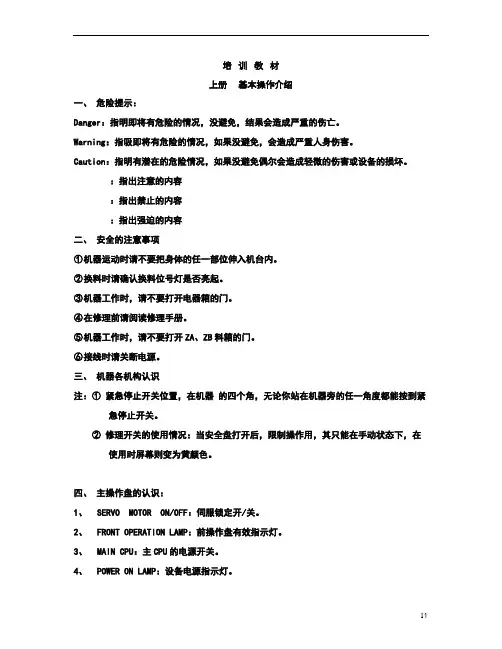
培训教材上册基本操作介绍一、危险提示:Danger:指明即将有危险的情况,没避免,结果会造成严重的伤亡。
Warning:指吸即将有危险的情况,如果没避免,会造成严重人身伤害。
Caution:指明有潜在的危险情况,如果没避免偶尔会造成轻微的伤害或设备的损坏。
:指出注意的内容:指出禁止的内容:指出强迫的内容二、安全的注意事项①机器运动时请不要把身体的任一部位伸入机台内。
②换料时请确认换料位号灯是否亮起。
③机器工作时,请不要打开电器箱的门。
④在修理前请阅读修理手册。
⑤机器工作时,请不要打开ZA、ZB料箱的门。
⑥接线时请关断电源。
三、机器各机构认识注:①紧急停止开关位置,在机器的四个角,无论你站在机器旁的任一角度都能按到紧急停止开关。
②修理开关的使用情况:当安全盘打开后,限制操作用,其只能在手动状态下,在使用时屏幕则变为黄颜色。
四、主操作盘的认识:1、SERVO MOTOR ON/OFF:伺服锁定开/关。
2、FRONT OPERATION LAMP:前操作盘有效指示灯。
3、MAIN CPU:主CPU的电源开关。
4、POWER ON LAMP:设备电源指示灯。
5、OPERATION READY ON:开机(指PANASET)。
6、OPERATION READY OFF:关机(指PANASET)。
7、START:开始开关,绿色错误信息的复位键。
8、STOP:停止键,相当于1 BLOOK。
9、RESET:复位。
10、HDD LAMP:CPU硬盘指示灯。
11、NUM LAMP:数字键指示灯。
12、CAPS LAMP:键盘字母大小写切换指示灯。
13、CL SCREEN:清屏14、TRACKBALL LEFT BUTTON:磁球的左键(执行键)。
15、TRACKBALL:鼠标功能。
16、ORG:原点回归。
五、副操作盘:ENABLE SWITCHES EB1、EB2:副操作盘执行开关。
1、HEAD NO. SELECT:HEAD1—5的选择。
客车电涡流缓速器制动性能试验研究买玉;杨良坤;刘鹏飞;屈怀琨;靖苏铜【摘要】为了研究电涡流缓速器的制动性能和热衰退性能,采用实车试验法进行研究.设计了空挡滑行、带挡滑行、空挡/缓速器制动、带挡/缓速器制动等4种试验方案,依据JT/T 721进行试验,分析空气阻力、滚动阻力、传动系统阻力等非缓速器制动因素对制动减速度的贡献量,得到带挡缓速器制动效果最优,并发现发动机制动与缓速器制动存在非线性叠加现象.【期刊名称】《交通节能与环保》【年(卷),期】2018(014)006【总页数】3页(P4-6)【关键词】电涡流缓速器;制动性能;热衰退性能;客车【作者】买玉;杨良坤;刘鹏飞;屈怀琨;靖苏铜【作者单位】北京中公高远汽车试验有限公司,北京 101103;国家汽车质量监督检验中心(北京通州),北京 101103;北京中公高远汽车试验有限公司,北京 101103;国家汽车质量监督检验中心(北京通州),北京 101103;北京中公高远汽车试验有限公司,北京 101103;国家汽车质量监督检验中心(北京通州),北京 101103;北京中公高远汽车试验有限公司,北京 101103;国家汽车质量监督检验中心(北京通州),北京101103;北京中公高远汽车试验有限公司,北京 101103;国家汽车质量监督检验中心(北京通州),北京 101103【正文语种】中文【中图分类】U463.50 引言当客车处于长距离下坡或频繁制动的工况时,其制动器急剧升温、制动热衰退效应明显,容易导致制动失效引发交通事故[1]。
电涡流缓速器作为汽车辅助制动装置,能够有效缓解制动器温度过高和制动器磨损等问题,从而保障人民生命安全。
电涡流缓速器是由定子总成、转子总成、支架以及电气控制系统等结构组成。
定子安装在车架上,转子安装在传动轴上并与传动轴同步旋转,两者通过电磁感应的原理来实现无接触制动[2,3]。
本文对装载电涡流缓速器的某车型客车进行了制动性能实车试验,并研究了电涡流缓速器的制动性能和热衰退性能。
电力系统专业英语精品文档发电机generator电压 voltage 母线bus 铁损 iro n loss 有功损耗active loss高压侧high side 低压 low voltage 稳定 stability 电厂 power pla nt 直流DC 开关站 switch station 并列的apposable三相故障 three phase fault 高顶值 high limited value 机端电压控制 AVR 功角 power angle 电抗器Reactor 功率因数 power-factor 功角 power-angle 无功负载 reactive load 电抗 reacta nee 上限 upper limit 负序阻抗 negative sequenee impedanee 功率因数power factor 额定rat ing 电压互感器PT 下降率droop rate 受端 receive-side 摇摆swing 刀闸(隔离开关)Isolator 励磁 excitati on 电流 curre nt 变压器 transformer 铜损 copper loss 无功损耗reactive loss 输电线 transmission line 中压 middle voltage 电压稳定 voltage stability 能量输送 power transfer 电网 powersystem 调节 regulati on 裕度margin分接头tap 静态 static(state ) 电抗 reacta nee 有功(功率)active power断路器Breaker 定子 stator 电压等级 voltage grade 档位 tap position 电导eonductanee 下限 lower limit 零序阻抗 zero sequenee impedanee 无功电流 reactive current 变比ratio 分接头tap 传递函数 transfer function 同步 synchronization 阻尼 damping 机端 gen erator term inal变电站 transformer substation 给永磁同步电机 Perma nen t-mag net Syn chro nism Motor电力系统 power system 励磁器excitor 升压变压器 step-up tra nsformer 空载损耗no-load loss 空载电流 no-load current 输电系统 power transmission system 高压 high voltage 功角稳定 angle stability 暂态稳定 transient stability 交流AC 落点 drop point 高抗 high voltage shunt (逃避)reactor 故障fault 切机 generator triping 动态 dynamic (state ) 电阻 resista nee 电容器Capacitor 电动机 motor 阻抗 impedanee 有功负载:active load PLoad 电阻 resistor 电纟内 susceptanee 正序阻抗 positive sequenee impedanee 无功(功率)reactive power斜率slope 参考值 referenee value 仿真分析 simulation analysis 框图 block diagram 保护断路器circuit breaker 无刷直流电机 Brusless DC motor异步电机 Asynchronous Motor三绕组变压器 three-colum n tran sformer ThrCI nTrans 双绕组变压器 double-colum n tra nsformer DbICIm nTrans 固定串联电容补偿 fixed series capacitor compe nsati on双回同杆并架 double-circuit lines on the same tower 单机无穷大系统 one machi ne - infinity bus system补偿度 degree of compensation 失去同步 loss of synchronization无功补偿 reactive power compensation 极限切除时间 critical clearing time 并联电容器 shunt capacitor< 线路补偿器 LDC(li ne drop compe nsatio n)自动控制理论 Automatic Con trol Theory 微机原理 Principle of Microcomputer 电路原理 Principle of circuits电力电子基 础Basic fun dame ntalsof power electr onics高电压工 程High voltage engin eeri ng励磁电流 Magnetizing current 电磁场:Electromagnetic fields 装机容量 in stalled capacity 故障切除时间 fault cleari ng time 强行励磁 rein forced excitati on 下降特性 droop characteristics电机学 Electrical Machinery 电磁场 Electromagnetic Field 电工学 Electrotechnics 电机学 Electrical Machinery电力系统稳态分析 State An alysis of Power System电力系统暂态分 析Power System电力系统继电保护原理 Electrical System's Relay Protectio n电力系统元件保护原理Prin ciple of Power System 's Element 电力系统内部过电压 Voltage within Power system模拟电子技术基础 An alogue Electr onic Tech ni que数字电子技 术 Tech ni que电路原理实验 of pri nciple of circuits电气工程讲 Steady-Tran sie nt-State An alysis ofPrin ciple ofProtectio nPastBasis ofDigital ElectricalLab.Lectures on电子专题实践Topics on experime ntal project of electr onics电气工程概论In troducti on to electrical engin eeri ng电子电机集成系统Electro nic machi ne system 电力传动与控制Electrical Drive andCon trol电力系统继电保护Power System Relayi ng Protectio n主变压器mai n tran sformer升压变压器step-up tran sformer降压变压器step-dow n tran sformer工作变压器operating transformer备用变压器sta ndby tran sformer公用变压器com mon tra nsformer三相变压器three-phase tran sformer单相变压器sin gle-phase tra nsformeron-load regulati ng 带负荷调压变压器tran sformer变压器铁芯tra nsformer core变压器线圈tra nsformer coil变压器绕组tra nsformer winding变压器油箱tra nsformer oil tank变压器外壳tra nsformer cas ing变压器风扇tra nsformer fantra nsformer oil 变压器油枕con servator( s drum变压器额定电压tra nsformer rated voltage变压器额定电流tra nsformer rated curre nttra nsformer voltage 变压器调压范围regulati on rage配电设备power distribution equipment SF6断路器SF6 circuit breaker开关switch按钮butt on隔离开关isolator,disc onn ector真空开关vacuum switch刀闸开关kn ife-switch接地刀闸earthing knife-switch电气设备electrical equipme nt变流器curre nt con verter电流互感器curre nt tran sformer电压互感器voltage tra nsformer电源power source交流电源AC power source直流电源DC power source工作电源operati ng source备用电源Stan dby source强电str ong curre nt弱电weak curre nt继电器relay信号继电器sig nal relay电流继电器curre nt relay电压继电器voltage relay跳闸继电器tripp ing relay合闸继电器clos ing relay中间继电器in termediate relay时间继电器time relay零序电压继电器zero-seque nee voltage relay 差动继电器differe ntial relay闭锁装置lock ing device遥控telec on trol遥信telesig nalisatio n遥测telemeteri ng遥调teleregulati on断路器breaker,circuit breaker少油断路器min i-oil breaker,oil-min i-mumbreaker高频滤波器high-freque ncy filter组合滤波器combined filter常开触点no rmally ope ned con tact 常闭触点no rmally closed con tact 并联电容parallel capacita nee保护接地protective earth ing熔断器电缆跳闸脉冲合闸脉冲一次电压二次电压并联电容器无功补偿器消弧线圈母线三角接法星形接法原理图一次系统图二次系统图两相短路三相短路单相接地短路device短路电流计算自动重合闸高频保护距离保护横差保护circuit curre nt纵差保护线路保护过电压保护母差保护瓦斯保护变压器保护电动机保护远方控制用电量载波故障选择性速动性灵敏性protectionprotectioncutout,fusible cutout cabletripp ing pulse clos ing pulseprimary voltage sec on daryvoltage parallel capacitorreactive power compe nsation arc-suppress ing coilBus,busbar delta conn ecti onWye conn ecti on schematicdiagram primary systemdiagram sec on dary systemdiagram two-phase shortcircuit three-phase shortcircuit sin gle-phase grou ndshort calculati on of shortcircuit automatic reclos inghigh-freqe ncy protecti ondista nee protecti on transverse differe ntial lon gitudinal differe ntial line protectionover-voltage protecti on busdiffere ntial protecti onBuchholtz protecti on transformer protecti on motorprotecti on remote con trolpower con sumpti on carrierfaultselectivityspeedsen sitivity可靠性reliability电磁型继电器electromag netic无时限电流速断保护in sta ntan eously over-curre nt protection跳闸线圈trip coil工作线圈operati ng coil制动线圈retra int coil主保护mai n protecti on后备保护back-up protecti on定时限过电流保护definite time over-current protection三段式电流保护the curre nt protecti on with threestages反时限过电流保护in verse time over-curre nt protecti on方向性电流保护the directi onal curre nt protecti on零序电流保护zero-seque nee curre nt protecti on阻抗impedanee微机保护Microprocessor Protectio n。

kema培训资料xx年xx月xx日CATALOGUE 目录•kema基础概念•kema进阶知识•kema的使用方法•kema的社区与支持01kema基础概念kema是一种常用于数据分析和数据预处理的编程语言和工具kema是一种以数据操作和数据处理为核心的编程语言kema可以帮助用户快速、高效地进行数据分析和数据挖掘kema是什么kema的用途数据挖掘和机器学习数据清洗和预处理统计分析数据可视化kema的基本结构kema中的数据结构包括向量、矩阵、数据框等,可以用来表示不同类型的数据数据结构kema中的变量和函数是程序的核心,变量用来存储数据,函数用来执行特定的操作变量和函数kema中的控制流语句包括if语句、for循环、while循环等,可以用来控制程序的流程控制流语句kema提供了一系列的函数库,包括数学函数、统计函数、字符串处理函数等,可以方便用户进行数据处理和分析。
函数库02kema进阶知识kema的常见问题及解决方案•常见问题一:Kema在特定情况下会出现性能问题,如何优化?•解决方案一:使用索引优化查询,减少全表扫描。
•解决方案二:合理规划分页查询,避免大量数据一次性加载。
•解决方案三:利用缓存技术,减少重复查询次数。
•常见问题二:Kema查询语句过于复杂,如何简化?•解决方案一:使用视图,将复杂查询封装成简单视图。
•解决方案二:引入Lambda表达式,降低查询复杂度。
•解决方案三:使用LINQ查询语法,提高查询可读性。
kema的高级应用•使用Kema进行数据库优化建模•概念模型设计,理解业务逻辑与数据模型之间的关系。
•选择合适的范式,如第三范式、BC范式等。
•数据分区、分片和索引设计,提高数据读写性能。
•使用Kema进行大数据处理和分析•使用Kema进行ETL过程设计,包括数据抽取、转换和加载。
•使用Kema进行数据仓库设计和构建,支持决策支持系统(DSS)。
•使用Kema进行数据挖掘和机器学习建模,实现数据智能分析。
最完整电力英语专业词汇知识中英文AA.B.C极密度继电器(第二报警值)Density relay For A.B.C. pole (2th alarm value)A.B.C极密度继电器(第一报警值)Density relay For A.B.C. pole (first alarm value)A.B.C极主储压器漏氮指示器Indicator for N2 leakage from the main accumulator of A.B.C.pole安(培) ampere (A)安全边界safety boundaries安全标志safety mark安全标准safety standard安全操作规程safety operation specifications安全措施safety measure / safety action安全电压safety voltage安全阀relief valve / safety valve安全阀打开Safety valve opening安全防护技术要求safeguarding specifications安全分析报告safety analysis report安全工程(学) safety engineering安全工作压力safe working pressure安全管理safety management安全技术措施safety technical steps (measurement))安全技术规程safety technical regulation安全距离safe distance安全可靠运行safe and reliable operation安全认证safety certification安全色safety color安全设[措]施maintenance prevention安全生产safety in production安全特低电压safety extra-low voltage安全限度safe limit安全性safety安全要求safety requirement安全裕度safety margin安全运行safe and reliable operation / safe operation 安全责任制system of safety responsibility安全注意事项safety precautions安匝ampere-turns安装erection / mounting / installation安装垫mounting pad安装费用installation cost安装和使用条件condition of installation and use安装和维护erection and maintenance安装结构mounting structure安装结构或间距mounting structure or spacing安装竣工检验final installation inspection安装孔fixing hole安装面mounting face安装平面mounting plane安装使用说明书instructions for installation & operation 安装说明mounting instruction安装条件mounting conditions安装图assembly drawing安装有…… be installed / be fitted with氨气检漏ammonia sniffing鞍型端子saddle terminal按钮push-button按钮开关push button actuator按生产要素分配distribution based on production factors 按照in accordance with (to) / according to按指数衰减的直流恢复电压exponentially decaying d.c. recovery voltage盎斯-英寸ounce-inch凹坑pit奥氏体austeniteB八小时工作制8-hour duty巴(表压) bar (gauge pressure)扒钉anti-cheking iron扒渣dross trap拔模斜度draft把...拆开take apart把M安装在N上fit M on N把M套在N上fit M over N把M装(插)进N fit M into N把手handle坝址dam site白班dayshift白点fish eye / flake白金white gold白金电极platinum electrode白口铁white cast iron白口铸铁white cast iron白铁皮white iron白噪声white noise百分比抽样检验percent sampling inspection and test 百分数percentage百分数导电率percent conductivity百分阻抗percentage impedance摆动wobble摆动焊welding with weaving; weave bead welding 摆动振动wagging vibration摆脱电流let-go current扳手wrench / spanner斑点spot搬运handling板材sheets板规(靠模)plate gauge (shaping plate)板坯slab板条箱(包装用)crate板牙screw plate / die-block半波half-wave / half-cycle / loop半波持续时间loop duration半成品semi-finished product半打(六个)half a dozen半导体semiconductor半导体层semiconducting layer半干法semi-dry method半个正弦波 a half sine wave半个周波one-half cycle半极half a pole半控half control半年度检验semiannual inspection and test半衰期half-life半小时half an hour半硬钢half-hard steel半圆棒half round bar半自动semi-automatic半自动的semi-automatic半自动焊semi-automatic welding伴随accompany棒料billet棒形绝缘子rod insulator包封encapsulating包封胶encapsulating compound包覆导体clad conductor包含体inclusion body包括include / comprise / contain包络线envelope curve包铅金属lead coated metal包税区bonded area包装package / packing包装标志packing mark包装标准packing standard包装箱packing box / packaging case饱和saturation饱和磁化强度saturation magnetization饱和度degree of saturation饱和效应saturation effect饱和因数saturation factor保持hold保持继电器keep relay保持经济适度快速增长maintain an appropriate rapid economic growth保持在合闸位置be held in closed position保持至少5分钟at least maintain for 5 min保护电抗器protective reactor保护电力间隙protection power gap保护电路protective circuit保护断路器back-up circuit breaker / protection circuit breaker 保护范围protective range保护火花间隙protective spark gap保护继电器protective relay保护开关back-up switch / protection switch保护水平protection level保护用互感器protective transformer保护装置protective equipment (device)保护装置的保护水平protection level of a protective device保护装置的保护因数protection factor of a protective device 保留垫板fusible (permanent) backing保留指数retention index保税区bonded area保温材料adiabator / thermal insulation material保温层lagging / thermal insulation保温加热器temperature-keeping heater保温冒口insulated feeder保温温度holding temperature保险insurance保险阀lock valve保险公司insurance company保险丝fuse / fuse wire保证ensure / assure / guarantee保证国家的长治久安guarantee China’s long-term stability 保证社会公共需要guarantee social needs报废riscard / refuse / scrap报废品scrapped product报告report报告编号reference of report number报警alarm报批for approval爆裂rupture爆破片bursting disks爆破片的误爆破unintentional rupture of bursting disk爆破压力rupture pressure爆炸性气体explosive gases杯状纵磁结构cup-shaped axial magnetic structure备份backup备件spare parts备料场charging area / charge make-up area备忘录memorandum (-book)备用prepared for use备用的辅助开关spare auxiliary switch备用面板blank panel备有…… be fitted with… / be equipped with …备注Remarks背板sheet backing背点ant-apex背对背电容器组back-to-back capacitor bank 背景情况background背景噪声background noise背景噪声水平background noise level背砂backing sand背压力back pressure背压式汽轮机back-pressure turbine倍频器frequency doubler被覆层coating layer / coat / coating被覆线coated wire被审核方auditee被试断路器the test circuit breaker焙烧baking本图This drawing本图对应断路器处于下列状态This diagram corresponds to the following conditions:本图供用户作液压柜-断路器本体(密度继电器、储压器漏氮指示器、接线盒)之间电缆联接参考用。

AA.B.C极密度继电器(第二报警值)Density relay For A.B.C. pole (2th alarm value)A.B.C极密度继电器(第一报警值)Density relay For A.B.C. pole (first alarm value)A.B.C极主储压器漏氮指示器Indicator for N2 leakage from the main accumulator of A.B.C.pole安(培) ampere (A)安全边界safety boundaries安全标志safety mark安全标准safety standard安全操作规程safety operation specifications安全措施safety measure / safety action安全电压safety voltage安全阀relief valve / safety valve安全阀打开Safety valve opening安全防护技术要求safeguarding specifications安全分析报告safety analysis report安全工程(学) safety engineering安全工作压力safe working pressure安全管理safety management安全技术措施safety technical steps (measurement))安全技术规程safety technical regulation安全距离safe distance安全可靠运行safe and reliable operation安全认证safety certification安全色safety color安全设[措]施maintenance prevention安全生产safety in production安全特低电压safety extra-low voltage安全限度safe limit安全性safety安全要求safety requirement安全裕度safety margin安全运行safe and reliable operation / safe operation安全责任制system of safety responsibility安全注意事项safety precautions安匝ampere-turns安装erection / mounting / installation安装垫mounting pad安装费用installation cost安装和使用条件condition of installation and use安装和维护erection and maintenance安装结构mounting structure安装结构或间距mounting structure or spacing安装竣工检验final installation inspection安装孔fixing hole安装面mounting face安装平面mounting plane安装使用说明书instructions for installation & operation安装说明mounting instruction安装条件mounting conditions安装图assembly drawing安装有…… be installed / be fitted with氨气检漏ammonia sniffing鞍型端子saddle terminal按钮push-button按钮开关push button actuator按生产要素分配distribution based on production factors 按照in accordance with (to) / according to按指数衰减的直流恢复电压exponentially decaying d.c. recovery voltage盎斯-英寸ounce-inch凹坑pit奥氏体austeniteB八小时工作制8-hour duty巴(表压) bar (gauge pressure)扒钉anti-cheking iron扒渣dross trap拔模斜度draft把...拆开take apart把M安装在N上fit M on N把M套在N上fit M over N把M装(插)进N fit M into N把手handle坝址dam site白班dayshift白点fish eye / flake白金white gold白金电极platinum electrode白口铁white cast iron白口铸铁white cast iron白铁皮white iron白噪声white noise百分比抽样检验percent sampling inspection and test 百分数percentage百分数导电率percent conductivity百分阻抗percentage impedance摆动wobble摆动焊welding with weaving; weave bead welding 摆动振动wagging vibration摆脱电流let-go current扳手wrench / spanner斑点spot搬运handling板材sheets板规(靠模)plate gauge (shaping plate)板坯slab板条箱(包装用)crate板牙screw plate / die-block半波half-wave / half-cycle / loop半波持续时间loop duration半成品semi-finished product半打(六个)half a dozen半导体semiconductor半导体层semiconducting layer半干法semi-dry method半个正弦波 a half sine wave半个周波one-half cycle半极half a pole半控half control半年度检验semiannual inspection and test半衰期half-life半小时half an hour半硬钢half-hard steel半圆棒half round bar半自动semi-automatic半自动的semi-automatic半自动焊semi-automatic welding伴随accompany棒料billet棒形绝缘子rod insulator包封encapsulating包封胶encapsulating compound包覆导体clad conductor包含体inclusion body包括include / comprise / contain包络线envelope curve包铅金属lead coated metal包税区bonded area包装package / packing包装标志packing mark包装标准packing standard包装箱packing box / packaging case饱和saturation饱和磁化强度saturation magnetization饱和度degree of saturation饱和效应saturation effect饱和因数saturation factor保持hold保持继电器keep relay保持经济适度快速增长maintain an appropriate rapid economic growth保持在合闸位置be held in closed position保持至少5分钟at least maintain for 5 min保护电抗器protective reactor保护电力间隙protection power gap保护电路protective circuit保护断路器back-up circuit breaker / protection circuit breaker保护范围protective range保护火花间隙protective spark gap保护继电器protective relay保护开关back-up switch / protection switch保护水平protection level保护用互感器protective transformer保护装置protective equipment (device)保护装置的保护水平protection level of a protective device保护装置的保护因数protection factor of a protective device保留垫板fusible (permanent) backing保留指数retention index保税区bonded area保温材料adiabator / thermal insulation material保温层lagging / thermal insulation保温加热器temperature-keeping heater保温冒口insulated feeder保温温度holding temperature保险insurance保险阀lock valve保险公司insurance company保险丝fuse / fuse wire保证ensure / assure / guarantee保证国家的长治久安guarantee China’s long-term stability 保证社会公共需要guarantee social needs报废riscard / refuse / scrap报废品scrapped product报告report报告编号reference of report number报警alarm报批for approval爆裂rupture爆破片bursting disks爆破片的误爆破unintentional rupture of bursting disk爆破压力rupture pressure爆炸性气体explosive gases杯状纵磁结构cup-shaped axial magnetic structure备份backup备件spare parts备料场charging area / charge make-up area备忘录memorandum (-book)备用prepared for use备用的辅助开关spare auxiliary switch备用面板blank panel备有…… be fitted with… / be equipped with …备注Remarks背板sheet backing背点ant-apex背对背电容器组back-to-back capacitor bank 背景情况background背景噪声background noise背景噪声水平background noise level背砂backing sand背压力back pressure背压式汽轮机back-pressure turbine倍频器frequency doubler被覆层coating layer / coat / coating被覆线coated wire被审核方auditee被试断路器the test circuit breaker焙烧baking本图This drawing本图对应断路器处于下列状态This diagram corresponds to the following conditions:本图供用户作液压柜-断路器本体(密度继电器、储压器漏氮指示器、接线盒)之间电缆联接参考用。
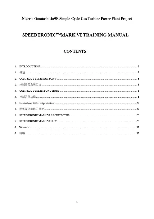
Nigeria Omotoshi 4×9E Simple-Cycle Gas Turbine Power Plant ProjectSPEEDTRONIC™MARK VI TRAINING MANUALCONTENTS1. INTRODUCTION (2)1. 概述 (2)2. CONTROL SYSTEM HISTORY (3)2. 控制器的发展历史 (3)3. CONTROL SYSTEM FUNCTIONS (6)3. 控制系统功能 (6)4. Gas turbine GEN. set protective (20)4. 燃机发电机组的保护 (20)5. SPEEDTRONIC MARK VI ARCHITECTUR (23)5. SPEEDTRONIC MARK VI 配置 (23)6. Network (58)6. 网络 (58)1. INTRODUCTION1. 概述The SPEEDTRONIC TM Mark VI Gas Turbine Control System is the latest derivative in the highly successful SPEEDTRONIC TM series. Preceding systems were based on automated turbine control, protection and sequencing techniques dating back to the late 1940s. The main functions of the MARK VI turbine control system are as follows:SPEEDTRONIC TM Mark VI燃机控制系统是最新推出的、最成功的SPEEDTRONIC TM系列的过程控制系统。
该系统继承了GE公司自20世纪四十年代以来的燃机自动控制、保护和顺序控制技术。

3 way valve 三通(路)阀a scavenge pipe 废料管a waste heat recovery boiler 废热回收炉abradable lining 磨损内衬/衬料 /ə `breidə bl/ /lainiŋ / actuated /`æktjueitid/ 起动的air baffle plate 空气阻板/挡板 /' bæfl/alloyed /ə`loid/ 合金aluminum alloy 铝合金 / ə`lju:minəm/an output shaft 输出轴annular duct casing 环形管箱arc /a:k/ 电弧arcing /`a:kiŋ/ 电弧放电armature /`a:mətjuə/ 电枢attachment /ə `tæt∫mənt/ 固定,安装axial ventilation fan轴向风扇axis 轴band /bænd/ 箍bandage /`bændeid3/ 箍,带base plate 底座,机座,底盘battery /`bætəri/ 电池bellcranks 钟形/报铃曲柄/曲轴Bevel gear 斜齿轮blading /`bleidiŋ/ 叶片,桨叶block valve 隔断阀blow-off valve 排气阀 /væ lv/bolt 螺栓borescope 检查孔,观察孔bracket /`brækit/ 托架,撑架bridge circuit 桥(接电)路bridge connection 桥接bus bar 母线by-pass 旁路,支管,分流(器)casing cover 机箱盖centrepiece /`sentəpi:s/ 十字头(轴、架)centrifugal 离心的,离心力 /sen`trifjugəl/chamber 室,舱check valve 止回阀clamp /klæmp/ 夹板,铁箍clutch /klΛt∫/ 离合器coalescent /kəuə`lesnt/ 聚结,凝聚,结合colander /`kΛləndə / 滤锅,滤盆combustion 燃烧combustor 燃烧室combustor pot 燃烧罐/瓶commutation 换向,整流,配电 /komju`tei∫n/compressor 压缩机compressor rotor drum 压缩机转轴conduct /kəndΛkt/ 导电/热conical drive shaft锥形传动轴control rod 控制杆converter 转换器,变压器 /kən`və:tə/copper alloy 铜合金 /`kopə/ / ə`loi/core 核,核心crank speed 曲轴速度cubicle /`kju:bikl/ 配电盘curing /`kjuəriŋ/ 硫化,固化current rating 电流负载 /`k∧rənt/ /`reitiŋ/curvic coupling 波形管damper winding 阻尼线圈/绕组 /`dæmpə/demister /di`mistə/ 去雾器,除雾器detector /di`tektə/ 探查器,探测器differential 微分的,微分discharge /`dist∫a:d3/ 排出,流出displacement 排量,气缸工作 /dis`pleismənt/ 量,排代 dome /dəum/ 圆顶downstream /`daunstri:m/ 向下游的,顺流的drive arm 驱动臂duct 导管/通风管duplex /`dju:pleks/ 双的,双方的,双重的earth brush /br∧∫/ 接地刷earth fault 接地故障 /ə:θ/ /fo:lt/eddy /edi/ 涡流,漩流eliminator /i`limineitə/ 消除器emission /i`mi ∫n/ 发射,发出Engine Management System (EMS)epoxy resin 环氧树脂 /e`poksi/exchanger /iks`t∫eind3ə/ 交换器(机, 剂), 换(放, 散)热器 excitation system 励磁系统excitation winding 励磁绕组Exciter 励磁exhaust stack 废料堆exterior /ik`stiəriə/ 外部的externalextraction /iks`træk∫n/ 抽出,排出,提炼extractor /iks`træktə/ 提取机,分离机,脱水机field winding 磁场绕组 /fi:ld/filtration /fil`trei∫n/ 过滤fitment /`fitmənt/ 装置,设备flange 轮缘,凸缘,底盘 /flænd3/Front bearing housing oil feed 前轴支架油料供给Front bearing housing oil scavenge 前轴支架油料排放Front bearing housing vent 前轴支架通风孔fuel manifolds 燃料进出管gas turbine 燃气轮机gearbox 齿轮箱generator 发电机glass-fabric /`gla:s`fæbrik/ 玻璃纤维的gravity /`græviti/ 重力gravity feed 重力自流进料ground resistor 接地电阻器 /graund/ /ri`zistə/hatch /hæt∫/ 舱盖,开口heat sink /siŋk/ 散热片,散热器helical spline coupling 螺旋形楔管high conductivity copper alloy strip高导电性/导热性铜片hot oil tank /tæŋk/ 热油箱/罐hub 轮轴,轮彀hydraulic ram actuator 液压冲压开关idle /`aidl/ 空载的,无功的igniter plug 点火开关ignition 点火电门impregnation resin 饱和树脂 /impreg`nei∫n/ /`rezin/ injector /in`d3ektə/ 注射器inner and outer bushes 内部和外部的衬套input 输入installation /instəlei∫n/ 装置instrumentation 仪器 /instrumen`tei∫n/integral part 组成部分 /`intigrəl/Inter compressor duct 内部压气机通道interface /`intəfeis/ 界面,分界面interior /in`tiəriə/ 内部的internal 内部的IP thrust compensation air 高压推进补偿空气island /`ailənd/ 独立的isolating /`aisəleitiŋ/隔离的,绝缘的joint 点,接点lamination /læminei∫n/ 金属板lever 杠杆lifting lug /l∧g/ 吊耳load /ləud/ 负载,负荷location bearing 定位轴 /ləu`kei∫n/lock washer 垫圈,皮圈low load control 低负荷控制LP and IP electronics 低压和中压电子设备LP thrust compensation air 低压推进补偿空气lubrication /,lu:bri`kei∫n/ 润滑magnet /`mægnit/ 磁力的 磁性的main body 主体malfunction 故障,失灵 /mæl`f∧ŋk∫n/manual /`mænjuəl/ 手工的,手动的maximum /`mæksiməm/ 最大的,最高的,最大值mechanical /mi`kænikl/ 机械的metering /`mi:təriŋ/ 测量,记录,调节mica /`maikə / 云母micron /`maikron/ 微米 micra /`maikrə/mineral /`minərəl/ 矿物,矿物质mini-disc 微型圆盘/片minimum /`miniməm/ 最小的,最低的,最小值mist /mist/ 雾module 机箱,模组moisture /`moist∫ə/ 湿度,潮气multi-cylinder 多气缸的 /mΛlti`silində/neutral /nju:trəl/ 中线的,中性的nozzle 喷嘴,管嘴oil distributor 分油器oil feed pipe 输油管oil filter 滤油器oil jet 气喷oil return hole 回油孔Oil/air seal 油/气封outer skin 外壳,外罩output 输出oven /`Λvn/ 加热室,恒温箱parallel /`pærəlel/ 平行的,同步的peak temperature 最高温度permanent /`pə:mənənt/ 永久的,永恒的pick-up 传感器piston 活塞,瓣Plunger 活柱顶塞,柱塞pneumatic /nju:`mætik/ 气动的,气力(风力,压气,气压)的port 右侧port 舱门,舷窗positional transducer 位置发射器power take off hub 动力启动轴pressing /`presiŋ/ 压,冲压primary /`praiməri/ 第一的,基本的,首要的,初级的priming pump 引液泵,启动注液泵 /`praimiŋ/ 液泵probe /prəub/ 探针quick action chamber 局部减压室quick action triple valve 快动作三通阀quick action valve 快动作阀,紧急阀quill /kwil/ 套筒,主轴ram position 冲压位置ratchet /`ræt∫it/ 棘轮,棘齿rated /`reitid/ 额定的RC (resistor capacity) 阻容rectifier /`rektifaiə/ 整流器,检波器,矫正器 rectifier /`rektifaiə/ 整流器reduction gearbox 减速齿轮箱 /ri`dΛk∫ən/regulator /`regjuleitə/ 调节器,稳定器relief valve 安全阀reservoir /`rezəvwa:/ 储存箱/池resistance /ri`zistəns/ 电阻,电阻器retainer /ri`teinə/ 固定器retaining nut 锁紧(固定)螺母 /ri'teiniŋ/ /nΛt/ reverse /ri`və:s/ 反的,相反的rib /rib/ 肋材,骨架ring 圆环roller bearing 滚轴Rotor 转子rotor winding 转子线圈/绕组Rpmscheduling /`skedju:liŋ/ 调度,编制进度表,工序,安排seal ring 密封圈secondary /`sekəndəri/ 第二位的,次要的,二级的self-acting control valve 自动控制阀self-sustaining speed 自持速度 /selfsəs`teiniŋ/shaft 轴sheet steel 钢板shell /∫el/ 外壳shield /∫i:ld/ 护板,挡板shockproof /`∫ok`pruf/ 耐(抗)震,耐电short circuit 短路 /`sə:kit/shunt /∫Λnt/ 转轨,转移shutdown 关机silicon diode 硅(晶体)二级管 /`silikən/ /`daiəud/ silver alloy 银合金 /`silvə/sleeve /sli:v/ 套(筒、管、环)sleeve bearing套筒轴承slip ring 滑环,集流圈solenoid valve 电磁阀 /`səulinoid/spill valve 溢油阀spool / spu:l/ 轴,线圈Spring 弹簧stage 分节,节starboard 左侧star-connected 星形接法,星形接线starter 启动/引燃装置starting system启动系统static stator 静态定子 /'stæ tik/Stator 定子Stator vanes 定子叶片stator winding 定子线圈/绕组 /`waindiŋ /strainer /`streinə/ 滤网,滤器Strut 抗压构件,撑子suction strainer 吸滤 /`sΛk∫n/support cone 圆锥形支架 /kəun/swash 挡板,阻板,旋转斜盘/swo∫/swirl /swə:l/ 涡流,漩流switch 开关,电闸,转换synthetic 综合,合成 /sin`θetik/tape /teip/ 胶布,绝缘胶布temperature /`temprət∫ə/ 温度terminal box 接线盒 /tə:minl/tertiary /`tə:∫əri/ 第三位的the air cooler 空气冷却机the can type combustion chamber 听/罐式燃烧室the cooling air intake /`inteik/ 冷空气吸入the differential pressure switch 压差开关,压差传感器the emergency lub oil pump /i`mə:d3ənsi/ 事故润滑油泵the grid synchronization frequency 热网同步频率the high-pressure shaftthe hot air exhaust 热空气排出the inner platform 内部平台 /`plætfəm/the intermediate pressure shaft (IP)the low-pressure shaft (LP)the LP bleed aperture doors 低压放气孔门the non return valve 止逆阀,单向阀the oil returns temperature 回油温度the Package Control System (PCS)thermal insulation strip 绝热片 /'θə:ml/ /insju`lei∫n/ /strip/ thermocouple 热力轴 /,θəməu`kaupl/thermo static control valve 恒温控制阀three phase winding 三相线圈 /feiz/torch /to:t∫/ 燃烧transformer 变压器trip 跳闸,脱扣,断开装置 /trip/trip circuit跳闸回路two-pole 两极upstream /`Λp`stri:m/ 向上游的,溯流的vacuum /`vækjuəm/ 真空vapour /`veipə/ 蒸汽,水蒸气variable frequency pump 可变(调)频率泵Variable Inlet Guide Vanes (VIGV’s) 可调进气口(导向)叶片variable stator vanes (VSV’s) 变距定子叶片ventilator /`ventileitə/ 通风设备voltage 电压water flow control valve 水流控制阀wedge /wed3/ 楔片,楔形物welded drum 熔接/焊接的 卷轴wound coil (迭层)线圈 /wu:nd/ /koil/。
GM China Engineering TrainingIntroduction toSTEERING SYSTEMSRack and Pinion Steering SystemsSection 5Participant’s Guide5. RACK AND PINION STEERING SYSTEM5.1 OverviewDelphi Saginaw’s first application for a rack and pinion gear was for Gran Prix of America in 1972. this gear was designed to fit into miniature race car and had a ratio of around 3:1. This was a manual gear only.The second application was for the AMC pacer. There were a power and a manual version. The gear had some very unique design features as well as some manufacturing processes. The pinion housing and the rack and cylinder assembly were injected together to set gear preloads and there was no adjustments on the gear. It had an automatic wear take up system. It also had formed pinion teeth created by a rolling process. These until were buit from 1975 to 1979.In 1976 Saginaw began building a more conventional manual gear for the Chevette. The gear was a refinement of an Opel design already in production. In later yearsof this program a power gear was added.In 1977-1979 Saginaw added additional power rack and pinion gear volume, doning a Chrysler gear for the OMNI and HORIZON in 1977, adding a SAAB application in1978, and adding GM “X” car in 1979. while these gears were more conventional than the Pacer gear, they were of a one piece aluminum housing design. This design had a number of process issues and was moved away from the 1982 models. The two piece design was introduced for this year model. It had a steel cylinder tube linked to an aluminum housing. This change was a cost saving with no mass penalty.From 1984 on a variety of applications have been added. A number of improvements and features have been added over the life of Saginaw gear programs including cast iron tophat, quiet valve, high temperature seals, hollow rack, variable ratio steering, SSS(Speed Sensitive Steering). Magnasteer, and a variety of process improvements. Today, rack and pinion systems are used on all front wheel drive models and some rear-wheel drive models.5.1.1. Basic Principle of Rack and Pinion GearFigure 5.1-1 shows the basic principle of rack and pinion steering. The steering shaft is attached to the pinion in the steering gear. The pinion, therefore, rotates with the steering wheel. Gear teeth on the pinion mesh with gear teeth on the rack. The rotating pinion moves the rack from side-to-side. The lateral action of the rack pushes and pulls the tie rods to change the direction of the vehicle’s front wheels.5.1.2. Rack and Pinion Design VariationsThere are two basic designs for Saginaw rack and pinion steering systems: end take-off and center take-off. Manual steering or power assist can be used on either design. The names indicate the location of the tie rods relative to the rack. On the end take-off design, the tie rods connect to the ends of the rack. The center take-off the rods connect the center of the rack. Figure 5.1-2 shows the basic differences in the two systems. Both designs have the same mechanical function. Choosing which version to use on a particular vehicular vehicle depends on the space. Weight, and other design considerations.5.1.3 Basic Rack and Pinion PartsThe turning motion applied to the steering wheel controls vehicles equipped with manual steering. When equipped with power assist system, vehicles only need reduced steering effort tocontrol their steering and, in some cases, reduced number of turns from lock to lock to improve emergency steering ability. Even if the power assist failure happens, a person can drive the vehicle but with increased steering effort.Since the design and operating principles of the manual gear are the same as the power gear, it is helpful to use the manual system to show the basic components common to all rack and pinion gears. Figure 5.1-3 shows the basic components of manual rack and pinion gears, which are also common to power-assist gears (which also include hydraulic-assist components).5.1.3.1. HousingThe housing is body-mounted or chassis-mounted, hollow metal body where the pinion and the rack engage.5.1.3.2. PinionThe pinion extends from the rack through an opening on top of the housing and attaches to the steering column or intermediate shaft. Gear teeth on the lower end of the pinion engage the gear teeth on the rack.5.1.3.3. RackThe rack is a long, around bar inside the housing. It has a cut gear surface where it engages the pinion. The inner tie rods are connected to the rack.5.1.3.4 Tie roadInner and outer tie rod connect the rack to the wheels to control the direction of the vehicle.◆End take-off (ETO): the tie rods connect to the ends of the rack and extend out fromopenings at each end of the housing.◆Center take-off (CTO): the tie rods connect to the center of the rack through a slot on thecenter of housing.5.1.3.5 Boot(s)Both the end and center take-off designs use flexible boots to cover housing openings and prevent internal damage and water intrusion.◆End take-off (ETO) (figure 5.1-2(a)): Boots on each end of the housing move back andforth with the rack; the boots expand and contract with the tie rods.◆Center take-off (CTO) (figure 5.1-2(b)): The center take-off design has a single, largeboot which surrounds the portion of the housing where the tie rods connect to therack. The boot expand and contract as the tie rods move back forth.5.1.4. Benefits of Rack and Pinion Steering SystemsThe benefits offered by rack and pinion steering systems include the following:◆Lighter weight for improved fuel economy.◆Space efficiency for tight design situations, particular for front wheel drive applications.◆Design flexibility to accommodate a wide rang of vehicle specifications.◆Compatibility with front-wheel drive vehicle design.◆Improved road feel, better handling, and more responsive steering.◆Durability. Compared to conventional steering systems, fewer things can go wrong with arack and pinion steering system.5.2. Manual Rack and Pinion Steering SystemThe figure 5.2-1 shows the assembly drawing of a manual steering gear. The pinion is supported in the rack and pinion housing by a lower bearing that is pressed into the housing. Typical manual steering gears utilize one-piece aluminum housing. Manual steering pinions are one-piece construction. The pinion is also supported by an upper bearing assembly that is positioned lengthwise on the pinion. The upper bearing assembly is held on the pinion by a retainer that is staked into a groove on the pinion. The upper bearing assembly slides into the housing with the pinion. Once the pinion is positioned in the housing, it is held firmly in place by a beveled retaining ring which fits into a groove in the housing. There is also a rubber lip seal which presses into the housing and seals between the housing and the pinion (figure 5.1-3 and figure 5.2-1).The rack is long round bar which has a number of gear teeth in a straight line. The gear teeth on the lower part of the pinion mesh with the gear teeth on the rack. Therefore, as the pinion rotates, the meshing of the gear teeth causes the rack to move back and forth sideways. Thus, the rotary motion of the steering wheel is converted by the steering gear into the lateral movement of the rack. The joint between the inner tie rod and the rack are protected from the environment by the boot seal.5.2.1. End Take-Off and Center Take-Off SystemsThe movement of the rack is transmitted by tie rod to the steering arms and wheels. There are two different ways tie rods connect to the rack: End take-off system and the center take-off system. Both designs have the same mechanical function. The systems’ names indicate the location of the tie rods relative to the rack. Choosing which version to use in a particular vehicle depends on the space, weight, and other design considerations. Refer to figure 5.1-2 to see the basic differences between the two systems.5.2.1.1. End Take-Off SystemThe Figure 5.2-1 shows the assembly drawing of a manual steering gear of end take-off design. On the end take-off system, the tie rods connect to the ends of the rack.The end take-off rack assembly is comprised of the following main components. A rack bushing is located in the housing and is held in place by a retaining ring. The steering rack then slides back and forth through the bushing (Figure 5.2-1 and Figure 5.2-2).A rack bearing slides into the housing and directly supports the steering rack. A spring is positioned between the bearing and an adjuster plug, which threads into the housing. The adjuster plug is secured in position by a locknut (Figure 5.2-2).The inner tie rod assemblies are threaded and staked to the steering rack. A shock dampener also snaps over each inner tie rod. The dampener minimizes noise at the end of rack travel and also determines the rack travel. Boots are secured to the housing with clamps. On some models the boots are also secured to the inner tie rods with clamps. The inner tie rod must be allowed to spin freely inside of the boots in order to adjust the vehicle toe. On other models, the boots fit tightly over the inner tie rods without requiring clamps. An outer tie rod assembly threads over each inner tie rod and is held in place with a locknut (Figure 5.1-3 and Figure 5.2-1).Figure 5.2-2 is an exploded view of a typical end tack-off rack and pinion steering assembly. The rack housing may be slightly different in some models from what is showm here, depending on the model and year vehicle.5.2.1.2. Center Take-Off SystemThe center take-off system functions in a similar manner to end take-off system, but is designed a bit differently. The center take-off tie rods connect to the center of the rack.Figure 5.2-3 shows the exploded view of a manual steering gear of center take-off design. This system has a bushing pressed into the housing through which the rack can slide. A rack bearing, spring and adjuster plug are positioned in this system the same way as for the end take-off system. Notice the front of the housing. It is not solid like the one used for end take-off, but rather has an open slot. This slot is often referred to as the window.When the rack is positioned in the housing, a rack guide is positioned in the front opening of the housing. A boot covers most of the housing, including the opening and the rack guide. The boot is secured to each end of the housing with clamps.The inner tie rod assemblies are connected to the rack at approximately the center of the housing where the opening is located. The bolts connecting the inner tie rods pass through and also connect the rack guide to the rack. The outer tie rod assemblies connect to the inner tie rods by a bolt, or stud, that threads into both the inner and outer tie rod. This is also an adjusting bolt that is used for toe adjustment during a front-end alignment.Except for the differences in some of their components, the center take-off and end take-off systems function the same.5.3. Power Rack and Pinion Steering SystemsDepending on the size and weight of a car and some other factors, including type of tires, tire pressure, gear ratio and road surface, the driver has to exert some amount of manual effort to turn the steering wheel. If the car is equipped with power assisted steering the driver does not have to exert as must effort to turn the wheel. Power rack-and-pinion steering systems are basically the same as mechanical systems, except for power assist components, as the manual rack and pinion. Therefore, if something happens to power assist, such as the pump belt breaking or the engine stalling, the driver can still maintain control and continue steering the car without the hydraulic assist.Basically, power steering is accomplished by adding a piston to the rack and sealing it within the housing. This, in effect, creates a hydraulic cylinder. When oil is sent under pressure from a pump and through a valve to one end of the hydraulic cylinder, it exerts a force that tends to push the rack in one directing. Directing the oil to the other end of the hydraulic cylinder pushes the rack in the other direction (Figure 5.3-1).5.3.1 Power Rack and Pinion Steering System Components5.3.1.1 End Take-Off systemFigure 5.3-2 is an assembly drawing of a typical power rack-and-pinion steering gear with end take-off. And Figure 5.3-3 is an exploded view of it. If you compare this with figure 5.2-1 and Figure 5.2-2, which is the manual rack and pinion gear with end take-off, you can see the difference between the two systems. As you’ll notice, the primary differences are in the housing, rack, and steering gear (pinion) because of the additional components for the power assist.In order for the power steering to work, a hydraulic cylinder is created in the rack-and-pinion housing.If the housing is a three-piece design, the cylinder tube, in conjunction with the piston acts as a hydraulic cylinder. The cylinder tube is pressed on to the rack housing and is secured by eitherdrive screws or by injecting plastic into the joint. The cylinder tube is typically made of steel.The valve housing (often referred to as the top hat) is pressed into the top of the rack housing and the joint is injected with plastic to secure it. The valve housing is usually made from cast iron, and the rack housing is usually made from die-cast aluminum.A piston is attached to the steering rack and slides back and forth in the cylinder. A Teflon ring acts as a seal between the piston and the cylinder a lip seal, called the inner rack seal, is pressed into the housing to act as a seal between the housing and the steering rack.An inner bulkhead fits into the housing and is located at the end of the cylinder. An outer bulkhead fits into the housing outboard of the inner bulkhead. The outer bulkhead has a lip seal pressed into it which provides a seal between the outer bulkhead and the rack (Figure 5.3-2). In addition, a rubber O-ring acts as a seal between the outer bulkhead and the cylinder tube. All these parts are held in place in the cylinder tube by a retaining ring which fits into a groove in the cylinder tube (Figure 5.3-2 and Figure 5.3-3).The rack is supported by a rack bearing that is positioned in the housing. There is a spring located between he bearing and an adjuster plug, which threads into the housing. The adjuster plug is secured in position by a locknut (Figure 5.3-3).Cylinder lines for the hydraulic oil are threaded into appropriate ports in the valve housing with O-ring seals providing the seal between the hydraulic lines and the valve housing. The cylinder lines are connected to the cylinder tube using flared end fittings. Just as with the manual rack and pinion steering system. The inner tie rod assemblies are threaded and staked to the rack. Boots are secured to the housing and, in some models, to the inner tie rods with clamps. The outer tie rod assembly threads over the inner tie rod and is secured in position with a locknut (Figure 5.3-4)There is one component in this area that is not provided on the manual rack and pinion. A breather tube is connected to the two boot seals for the inner tie rods (Figure 5.3-4). This breather tube is very important since it transfers air between the two boot seals as they collapse and extend. If a hollow rack is used, the air is often transferred through the middle of the rack, not requiring a breather tube. This tube is not necessary on a manual system since the transfer of air can occur inside the steering gear, which is not sealed like the one on the power system.It is also very important that the breather tube be installed at all times. If the tube is missing during operation of the rack and pinion. Dirt can be sucked into the boot seal hole where the tube should be positioned.The lower pinion components of the power rack-end-pinion steering system are illustrated in Figure 5.3-2 and 5.3-3. the lower pinion thrust bearing is pressed into the housing and is secured here by a retaining ring that fits into a groove in the housing. The upper pinion bushing and lip seal are also pressed into the housing. The pinion is positioned in the upper and lower pinion bearings. A nut threads over the bottom of the pinion and secures it firmly to the lower bearing. A dust cover is pressed into the lower part of the housing to shield the lower pinion components. On the upper part of the pinion is a retaining ring which snaps into a groove in the spool shaft. Above the retaining ring is an annulus into which the spool shaft bearing is pressed. A rubber primary lip seal and a dust seal are pressed into the upper part of the housing to provide a seal between the spool shaft and the housing. A retaining ring secures the two seals (Figure 5.3-2 and Figure 5.3-3)5.3.1.2. Center Take-Off SystemFigure 5.3-5 is an assembly drawing of a typical power rack-and-pinion steering gearing with center take-off. And Figure 5.3-6 is an exploded view of it. If you compare this with Figure 5.2-3, which is a manual rack and pinion gear with center take-off, you can see the differences between the two systems. As you’ll notice, the primary differences are in the housing, rack, and steering gear (pinion) because of the additional components for the power assist.Besides the differences associated with how the tie rods connect the rack, which manual gears have, there are distinct differences in the hydraulic cylinder and rack between power center take-off and end take-off systems. As can be seen in Figure 5.3-5 and Figure 5.3-6, the piston has different effective hydraulic areas at its different sides. In order to compensate the uneven power assist to one side and another, it is necessary to take certain measures.5.4. Basic Power Assist Operation5.4.1. Hydraulic PathsFigure 5.4-1 shows a typical hydraulic system in which a mechanical pump uses an internal vane rotor to generate hydraulic fluid pressure. The pump then forces fluid through a hydraulic hose to a valve assembly which is part of the steering gear.For power rack and pinion gears, the valve assembly is attached to the top of the pinion (see Figure 5.3-2, 5.3-3, 5.3-5, and 5.3-6).the valve directs the fluid to the appropriate parts of the system where hydraulic force is converted into mechanical movement.Figures 5.4-2 and 5.4-3 respectively shows typical system flow path and gear flow path of rack and pinion steering system. Hydraulic fluid from the power steering pump is delivered via the power steering hoses to the ports in the valve housing (or tophat). The power steering (rotary) valve then can direct available pump pressure to either side of the steering rack piston to assist the driver’s input as required. Fluid leaving the nonpressurized side of the piston flows through its cylinder line to the return passages of the valve and back to the pump reservoir. when no assist is required, the fluid flows internally within the valve and is returned to the pump. This open-center type system results in pump load when required.5.4.2. Rotary Valve Function5.4.2.1 Steering Gear Valve Body AssemblyThe steering gearing gear valve body assembly uses a spool valve to direct hydraulic fluid to the appropriate steering gear chamber. Valve operation is similar for both integral gears and rack and pinion gears. This section illustrates valve operation for rack and pinion systems. The valve assembly includes the following components (refer to Figure 5.4-4)◆Valve Body—The valve body provides a hydraulic interface between the gear housingand the spool shaft. Grooves and seal ring on the OD provide fluid path connectionsbetween pressure, return, and cylinder paths. Grooves on the ID interfacehydraulically with the spool shaft to direct fluid flow to provide the desired steeringassist.◆Spool Shaft—the spool shaft not only provides a mechanical connection with theIntermediate Shaft, but also directs fluid flow to provide the desired steering assist.Physical variations of the valving surfaces on the spool shaft dictate the ultimatesteering feel of the vehicle. These variations, such as groove width, flat width, angleand length, are performed on the spool shaft instead of the valve body since it ismuch easier to do.◆Torsion Bar—the Torsion Bar is nothing more than a spring which returns the valve to itsneutral position. The diameter of the bar dictates its torsional rate, and this is aninfluencing factor on valve effort. One end of the bar is retained in the pinion, andthe other end is pinned to the spool shaft as the valve is balanced.◆Drive Pin—The Drive PIN is the connecting link between the pinion and the valve Body.It is pressed into a heat treated portion of the pinion and rides in a hole in the valvebody. Since the valve body is the floating component in the rack and pinion valve, astraight-sided pin would tend to bind and lock the valve body if perfect alignment ofpin to hole is not achieved. Hence, the head of the pin is milk-bottle shapedproviding little more than point contact with the body hole ID. The top end of thepinion is attached to a valve assembly (see Figure 5.3-2, 5.3-3,5.3-5, and 5.3-6). Thevalve body rotates within the housing bore. There are annular grooves on the outsideof the valve body which connect with oil hold in the housing. The purpose of theseholds is for supplying oil from the pump and directing it to either end of the steeringcylinder bore. Teflon rings provide a seal between the valve body and the housing.There are also holes through the wall of valve body which connect the outsidegrooves with the longitudinal slots on the inside surface. These inner surface slotsform one-half of the valving interface (where the oil valving is done). (Figure5.4-4).A torsion bar is pressed and staked into the top end the pinion. There is also a drive pin in the head of the pinion which fits into a hole in the valve body. This then locks to the valve body, the lower end of the torsion bar and the pinion, allowing them to rotate as through they were one solid component (Figure 5.4-4).The spool shaft (input shaft) of the gear assembly is attached to the upper end of the torsion bar with a pin (Figure 5.4-4). This allows the spool shaft and the upper end of the torsion bar to rotate together as through they were one solid component.Longitudinal slots are cut into the outside diameter of the spool shaft and interact with the longitudinal slots on the inside surface of the valve body. This interaction forms the other half of the valuing interface.Holes that go through the spool shaft wall allow the oil to flow back to the pump. There are splines in the bottom of spool shaft which allow the spool shaft to fit loosely into splines in the top of the pinion (Figure 5.4-4) there is a certain amount of rotational movement available in the splines of the spool shaft and pinion. And this movement is called valve travel. The splines provide mechanical backup in the case of hydraulic failure.5.4.2.2 Vavling OperationThe amount of hydraulic assist that is provided in a power steering system is directly related to, and controlled by, the drive. This is because as the drive turns the steering wheel, he controls the operation of the steering gear valve. The valve, in turn, is a very important component in controlling the hydraulic response to the drive’s turning of the steering wheel. The actual operation of the valve is as follows.It has been shown that the spool shaft and upper end of the torsion bar rotate as one part. Thevalve body, pinion and lower end of the torsion bar act as another solid part. One part is then considered the action side and the other part is considered the resistance side. The torsion bar, which is a rotational spring, is the connection between the two parts (figure 5.4-5). When the diver turn the steering wheel, the action side of the steering gear, which is the spool shaft and upper end of the torsion bar, rotates with the steering wheel. The resistance side, which is the valve body, pinion and lower end of the torsion bar, does not move at first but does sense the resistance to turning at tires. Since the valve body is not rotating, valving begins to take place and oil is sent under pressure to the appropriate end of the rack cylinder.As the steering wheel and spool shaft continue to rotate, the oil pressure increases and the hydraulic force acting on the steering rack piston is large enough to overcome the turning resistance at the tires. When this happens the piston, rack, tie rods and tires start to move.If the drive continues rotating the steering wheel, the spool shaft will rotate within the valve body only as much as is required to overcome the turning resistance at the tires. The spool shaft will then maintain that position relative to the valve body, even though both parts, action and resistance, of the steering gear assembly are rotating within the gear housing.When the driver releases the steering wheel, the torsion bar unwinds and returns the spool shaft to a central position within the valve body. If the car is moving, the aligning forces from the tires help both the action and resistance sides of the steering gear assembly to rotate to the straight-ahead position.Figure 5.4-6 is a cutaway view of a valve is in a centered position, oil from the pump flows into the valve through four supply holes (ports) in the valve body. This valves is an open center valve, meaning that the oil is freely ported to both sides of the cylinder and to the return flow back to the pump.Figure 5.4-7 shows the valve in full right turn as performed in a parking maneuver. Again, input or pressure fluid enters the valve, but since the gaps to the left turn cylinder holes and closed, it enters the right turn cylinder holes since the gaps to return are also closed. Under these conditions, no flow from pressure to return takes place, the fluid is under extremely high pressure and maximum assist occurs. As the fluid actuates the hydraulic piston and motion occurs the fluid in the left turn side of the cylinder is forced out thru the cylinder lines and back to valve. Here it enters thru the left turn cylinder holes in the valve body, and since the gap to return is wide open, it flows out the return passages. Figure 5.4-7 shows two extreme positions of the valve. During normal steering, however, the valve seldom is fully actuated. Partial flow occurs to one of the sets of cylinder passages, and manipulation of the cross sectional areas thru which flow takes place and by selection of a desirable torsion bar diameter, the handling characteristics of the vehicle are determined and enhanced.5.4.3. Valve Plot TypesWhen a valve needs to be designed, and certain parameters must be met, it is desirable to depict these parameters graphically. Hence, two basic types of curves depict the functional characteristics of a certain valve. One is the pressure-effort curve, the other is the response curve. The pressure-effort curve shows the amount of steering effort required to build a certain steering assist pressure, and the response curve shows how far the valve has to rotate to build that pressure. Typical curves are shown in figures 5.4-8 and 5.4-9.One of the ways to change the shapes of those two types of curves is to change the diameter of the T-Bar (Torsion Bar). Figure 5.4-10 illustrates the effect of torsion bar diameter on valveeffort. The larger the T-Bar diameter, the bigger the amount of steering effort required to build a certain steering assist pressure.Using these two basic curves plus the data from vehicle evaluations, a valve is developed to meet certain customer specifications.5.4.4. Valve Balance and EffortWith the steering assembly mounted in an appropriate. Fixture, rotate the valve all the way to the right corner and read effort required to build a 0.69 Mpa differential pressure. Rotate the valve all the way to the left corner and repeat the reading. Valve effort in each corner at 0.69 Mpa to be within 0.46 N.m of each other and to be within the limits as specified on the appropriate valve and pinion assembly chart.5.4.5. Hardness of Valving SurfacesThe valve should be heat treated in order to meet the certain requirement for hardness of its valving surfaces. True, the valve will function the same whether its components are heat treated or not, but let us go one step further. The presence of foreign material in the steering system is virtually unavoidable. Whether in some isolated instances machining chips are left in the components or debris is introduced into the system thru service by the customer, it can and will happen. These foreign particles are capable of entering the valve. If the valving surfaces of a valve are not hard enough to chew up them, it may be caused to bind after a relatively shorter period of work. However, heat treated valving surfaces have the ability to chew up foreign particles and continue functioning.5.4.6. Quiet ValveThe original valve designed for rack and pinion steering was a down-size copy of the integral gear valve complete with its hiss characteristics. At that time, no consideration for hiss reduction was given to the design since adequate noise isolation was provided by the intermediate shaft. In the evolution of the American front-wheel drive automobile, ride stiffness became an important factor. On-Center compliance was partially reduced by stiffer compounds in the intermediate shaft pot joint. This had a tendency to degrade the noise isolation qualities of system, and hiss suppression became an issue to be addressed.Integral gear valve and early rack and pinion valves have velving surface arranged in such a manner that a three-step metering process is accomplished. This concept was incorporated into the integral gear valve to reduce valve squawk. As full actuation of the valve takes place and valving gaps are sequentially closed until just before final shutoff, two pressure gaps allow all the fluid to flow thru them at tremendous pressure and velocity. Studies at the time had shown that hiss is affected by fluid velocity, temperature and pressure. A valve with equal gaps, where fluid shutoff occurs simultaneously on all involved valving surfaces, was conceived and developed. Here final shutoff occurred thru all eight involved valving gaps, reducing fluid velocity thru a given passage thus reducing valve hiss. Implementation of this concept, however, proved to be cumbersome to say the least. In fact, subsequent experimentation revealed that in order for this concept to work, parts had to be made with unimaginable precision, virtually eliminating any tolerances at all.Another part of the problem also was that fluid metering took place over sharp edges.Further reduction in valve hiss was accomplished by having metering flats ground onto the。
洛阳凯迈电涡流缓速器培训资料 CAMA Electromagnetic retarder Training Material
凯迈(洛阳)机电有限公司 CAMA(luoyang) Electromechanic Equipment Co.,Ltd DHB系列缓速器培训资料
凯迈(阳机)机电有限公司 1 目 录 DIRECTORY 电涡流缓速器原理…………………………2 Electromagnetic retarder principle 主机总成及安装……………………………5 The retarder assembly part 电器总成及安装……………………………11 The Electric System 维护与保养…………………………………33 Maintenance 故障与排除…………………………………38 Troubleshooting DHB系列缓速器培训资料
凯迈(阳机)机电有限公司 2 电涡流缓速器原理 Electromagnetic retarder principle 缓速器基本原理是电磁感应现象 1855年,法国物理学家Leon FOUCAULT先生发现了电磁感应现象. The working principle of electromagnetic retarder is electromagnetism induction, which is found by physical scientist Leon FOUCAULT in 1855.
电源断开时铁锤急速下降 Hammer dropped quickly when power is off. 电源接通时铁锤缓速下降 Hammer dropped slowly when power is on. DHB系列缓速器培训资料
凯迈(阳机)机电有限公司 3 定子固定安装在汽车底
线圈装在定子上 DHB系列缓速器培训资料
凯迈(阳机)机电有限公司 4
DHB系列缓速器培训资料
凯迈(阳机)机电有限公司 5 主机总成部分 The retarder assembly part 目前我公司能提供与进口ZF S 5-80/S6-90变速箱、綦江S6-90、
QJ1506、S5-80变速箱、铁马变速箱、大同变速箱、一汽解放系列变速箱和陕齿富勒系列变速箱等相匹配的电涡流缓速器。下面以DHB20A缓速器在綦江S6-90变速箱后端盖上安装为例,介绍缓速器的安装过程。(在其它变速箱上的安装,除了定子支架稍有不同之外,其他过程基本相同) An electromagnetic retarder which is a frictionless braking system used in vehicle can be attached to the rear part of the gear box, the rear drive axle, or in between the driving shafts. Up to now Nanfeng company can provide the electromagnetic retarders which are matched with
电磁场在转子产生电涡流
转子叶片通过风冷散发制动能量 DHB系列缓速器培训资料
凯迈(阳机)机电有限公司 6 imterminaled ZFS5-80/S6-90, QiJiang S6-90/S6-85/S5-80, TieMa, DaTong,
FAW series, DongFeng series of gear boxes and etc. In order to introduce operator to the retarder installation, the process of mounting the DHB20A retarder to the rear part of QiJiang S6-90 gear box is taken as an example. (Except for the stator brackets, the installing processes of the other components which are attached to gear boxes are similar to the DHB20A)
●安装示意图:Scheme of Installation:
4 5 6 7 8 9 10 11 12 3 2 1
图(1) Diagram(1)
●零组件汇总表PART LIST DHB系列缓速器培训资料
凯迈(阳机)机电有限公司 7 序号 ITEM 名称 DESCRIPTION
数量QTY
1 六角螺母M12、弹簧垫圈12 Nut M12, Spring Washer 12 4 2 后转子 Rear Rotor 1
3 六角螺栓M12×90、双头螺柱M12×80、螺母M12、弹簧垫圈12、平垫12 Hexagon Bolt M12x90, Spring Washer 12
8
4 定子总成 Stator Assembly 1 5 双头螺柱M16×1.5,螺母M16×1.5、弹簧垫圈16 Stud Bolt M16x1.5, Nut M16x1.5, Spring Washer 16 8 6 传动轴法兰 Driving Shaft Flange 1 7 六角螺栓M16×1.5×30、轻型弹簧垫圈16 Hexagon Bolt M16x1.5x30, Spring Washer 16 8
8 前转子总成 Front Rotor Assembly 1 9 六角螺栓M22×1.5×55、弹簧垫圈22 Hexagon Bolt M22x1.5x55, Spring Washer 22 4
10 M形调整垫片 M-shape Spacer Spool 按需 a set 11 支架 Bracket 1
12 变速箱端盖和输出法兰 The special rear unit of gear box and output flange 1
★注意:在缓速器安装前应确保车前后轮不能移动,断开原车电源,并用高度尺测量变速箱箱体端面与变速箱输出法兰端面之间的距离,应为193mm;用百分表测量变速箱输出法兰的轴向窜动量应小于0.3mm;径向和轴向跳动量均应小于0.05mm;变速箱输出法兰端面的平面度应小于0.1mm。如不符合则换装符合要求的变速箱。 ●IMTERMINALANT NOTICE: It must be ensured that the fore and rear DHB系列缓速器培训资料 凯迈(阳机)机电有限公司 8 wheels of the vehicle are not moved before installing the
retarder, and the main switch of battery is off; the distance between the end surface and output flange of gear box housing, measured by height gauge, should be 193.5mm; the axial play of the gear box output flange measured by dial indicator should be less than 0.3mm; the radial play should be less than 0.05mm; the planeness of the output flange end surface of the gear box should be less than 0.1mm. If the conditions mentioned above can not be met, substitute with the qualified gear box.
★电涡流缓速器安装步骤 Assembly of electromagnetic retarder: 注意!!!缓速器上的所有螺栓、螺母、螺杆处必须涂抹乐泰270或相同强度螺纹锁固剂! IMTERMINALANT NOTICE: It must be ensured that all bolts, nuts and threaded rods are daubed with LETAI 270 or the same step thread locker! 1.安装支架(序号11):Installation of Bracket (Item 11) 用4个六角螺栓M22×1.5×50、弹簧垫圈22、 (序号10),将支架(序号11)固定在变速箱后端盖(序号12)上,螺栓紧固力矩为230~250Nm。(注意:操作时不能损坏原车体) The bracket (Item 11) should be fixed to the rear unit of gear box
(Item 12) by 4 hexagon bolts M22x1.5x55, spring Washers 22with fastening moment of 230N.m ~250N.m. (Note: The vehicle body can not be damaged while operating) 2.安装缓速器主机总成 Installation of Retarder Assembly