CR5100D-C说明书
- 格式:doc
- 大小:757.00 KB
- 文档页数:4

CAN 转 485 说明书CAN to 485 manual深圳市欧诺克科技有限公司一、接线说明(1)J1端子模块供电电源(直流20-90V),+HV 电源正,GND 电源负(2)J2端子485接口。
如果B 和R 短接,表示485接终端电阻(3)J3端子CAN 接口(和伺服的网线接法是平行网线压法)(4)S1 选择485的波特和检验位(参考通信设置中的说明)(5)本通信卡最多可以带16台从站,典型网络图如下CAN 转485型号说明090 - MRTUCANC:CANMRTU:远程控制终端远程控制终端090:18~90V 180:18~180VRS485R:RS485C R额定电压制动电阻型号汇总驱动器型号电压CR090-MRTU 18~90VDC CR180-MRTU18~180VDC二、通讯设置1、485通讯设置(1)波特率与校验2数据位模块内部 J5-MDB 位跳线帽插上为 8 取出为 7 (默认为8)。
3停止位模块内部 J5-MSB 位跳线帽插上为 1 取出为 2 (默认为1)。
旋钮 S1 的值波特率校验09600None119200None238400None357600None4115200None59600Odd619200Odd738400Odd857600Odd9115200OddA9600EvenB19200EvenC38400EvenD57600EvenE115200EvenF115200Even2、CAN通讯设置Can波特率(默认为1000k)(1) 模块内部J5-CB1~3为CAN波特率设置CB1CB2CB3波特率ON ON ON1000kOFF ON ON800kON OFF ON500kOFF OFF ON250kON ON OFF125kOFF ON OFF50kON OFF OFF25kOFF OFF OFF1000k三、地址寄存器索引表(4X)序号CAN_INDEX(HEX)MODBUS ID(DEC)长度(字节)操作方式说明1100C1102RW CANopen节点保护时间,配合0x100D使用,单位(ms)可以向系统站ID为166写入数值向所有子站发送2100D1111RW CANopen节点保护因子,和0x100c的乘积,为节点保护时间可以向系统站ID为166写入数值向所有子站发送3781节点保护(发送数据0x5A5A,可以向系统站ID为166写入该值向所有子站发送保护帧)4791NMT操作(网络管理)1:操作 0x80预操作 0x81复位节点可以向系统站ID为166写入数值向所有子站发送56040802RW控制字(附表一)660411202R状态字(附表二)710021224R驱动器状态寄存器821801244R紧急状态寄存器921811264R事件锁存寄存器1021841124R CANopen限制状态掩码116060811RW CAN模式的控制模式选择(附表三)1260611211R CAN操作模式显示132300822RW操作模式(附表四)1410011281R1521201144RW跟随错误窗口1621821164R故障掩码1721831294R锁存故障寄存器182310884RW模式选择1960641314RW电机实际位置(count)2060691334R电机实际速度(0.1 counts/sec)21221c1352R电机实际电流(0.01 amps)2222001362R模拟量输入(mv)2322011372R母线电压(0.1V)2422021382R驱动器温度2521901402R端子输入状态262191902RW端子上下拉电平选择272194912RW端子输出状态与控制28606704RW位置跟随窗口29606822RW位置跟随窗口时间3060F434R位置错误3160FB:152RW位置环比例(Pp)3260FB:262RW位置前馈()3360FB:372RW速度前馈()3460FB:482RW增益倍数35607D:194RW软件负限位,回零后有效36607D:2114RW软件正限位,回零后有效372253134RW接近软件限制时的减速率12100154RW速度环最大加速度(1000counts/s2)22101174RW速度环最大减速度(1000counts/s2)32102194RW速度环紧急减速度(1000counts/s2)42103214RW速度环最大速度(0.1counts/sec)52104234RW速度误差窗口6606d252RW72105262RW速度错误窗口时间82341274RW命令速度(0x2300设成11时的速度模式,速度值)960F9:1292RW速度环比例增益(Vp)1060F9:2302RW速度环积分增益(Vi)1160F9:3312RW1260F9:4322RW1360F9:5332RW电流环参数12110342RW峰值电流(0.01amps)22111352RW持续电流(0.01amps)32112362RW I2t时间 (ms)42113374RW命令电流增加率(mA/sec)52340392RW命令电流(0.01amps)660f6:1402RW电流环比例增益(Cp)760f6:2412RW电流环积分增益(Ci)860f6:3422RW电流偏移96071732RW目标扭矩rated torque/1000106076744RW额定扭矩函数发生器功能12330832RW函数发生器配置 8193:梯形波形 2:正弦波形22331842RW函数发生器的频率(Hz)32332854RW函数发生器的幅度42333872RW发生的占空比 , 方波有效(0.1%)回零模式参数16098431RW回零模式选择(在软件配置)26099:1444RW回零高速速度(0.1counts/sec)36099:2464RW回零低速速度(0.1counts/sec)4609A484RW回零时的加减速(10counts/sec2)5607C504RW原点偏移位置(counts)62351522RW硬停止回零模式延时(ms)72350532RW硬停止模式电流(0.01A)82352542RW原点偏移位置(counts)位置模式12121554RW S曲线的加加速度(100counts/sec2)222521412R轨迹曲线状态321221424R轨迹生成器目标位置.脉冲输入时有用4607A604RW给定目标位置56081624RW轨迹位置模式生成器的速度(0.1counts/sec)660FF644RW轨迹速度模式生成器的速度(0.1counts/sec)76083664RW加速度(10counts/sec2)86084684RW减速度(10counts/sec2)96085704RW急停减速度(10counts/sec2)106086722RW轨迹曲线模式选择 0:是梯形曲线 3:是s形曲线 -1:只走速度驱动器状态信息130R 输出短路231R 驱动器过温332R 过电压433R 电压低534R 电机过温635R 输出电源故障736R 电机相序错误837R 输出电流限制938R 输出电压限制1039R 正限位故障1140R 反限位故障1241R 硬件没使能1342R 软件没使能1443R 停止电机1544R 电机刹车激活1645R PWM 输出没激活1746R 软件正限位1847R 软件负限位1948R 跟踪错误2049R 跟踪报警2150R 驱动器处于复位状态2251R 位置错误2352R 驱动器故障2453R 速度限制2554R 加速度限制2655R 位置误差大于误差警告2756R原点信号激活16410:2952RW 电机极数26410:0B 964RW 电机最高速度(rpm)36010:17984RW 电机编码器分辨率(counts)驱动器属性16510:31502R 驱动器峰值电流26510:41512R 驱动器持续电流36510:51522R I2t 时间46510:61532R 驱动器最高电压56510:71542R 驱动器最低电压66510:91552R驱动器最高温度四、线圈寄存器地址(0X)序号CAN_INDEX (HEX)MODBUS ID (DEC)长度 (字节)操作 方式说明10R 输入端子对应MODBUS 地址,0对应IN1,1对应IN2如此类推220R 输出端子对应MODBUS 地址,20对应out1,21对应out2如此类推380W 保存参数484W 驱动器复位585W 故障清除686W实际位置清零序号CAN_INDEX (HEX)MODBUS ID (DEC)长度 (字节)操作方式说明102R 固件版本212R 485旋钮值322R 卡内部J5值444R Rs485波特率562R Rs485校验位672R Rs485停止位782R Rs485数据位892R 485错误信息9102R CAN 波特率10112R 卡最多支持站号11122R 当前站数12132R Can 错误信息13164R CAN 总线ESR 14182R ESR Rec 15192R ESR Tec 16202R ESR Lec 17212R ESR BusOffBit 18222R ESR EPVF 19232R ESR EWGF20252R 有效站位.4X25-4X4021781RW 所有站发送节点远程帧22791RW 所有站发送NMT 231101RW 所有站发送节点时间241111RW所有站发送节点时间因子2857R (位置模式)运动中2958R 位置误差大于误差警告3059R 相序未初始化3160R PMW 命令错误3261R CRC 错误3362R 驱动器内部错误3463R 过电流3564R FPGA1错误3665R FPGA2错误3766R 安全电路故障3867R 电流超控3968R 电机绕组未连接4069R 4170R节点错误五、CAN 转485模块信息(4X )(1) 寄存器说明(2)通信指示灯状态显示485 端指示灯:1)绿灯快闪通信正常收发。
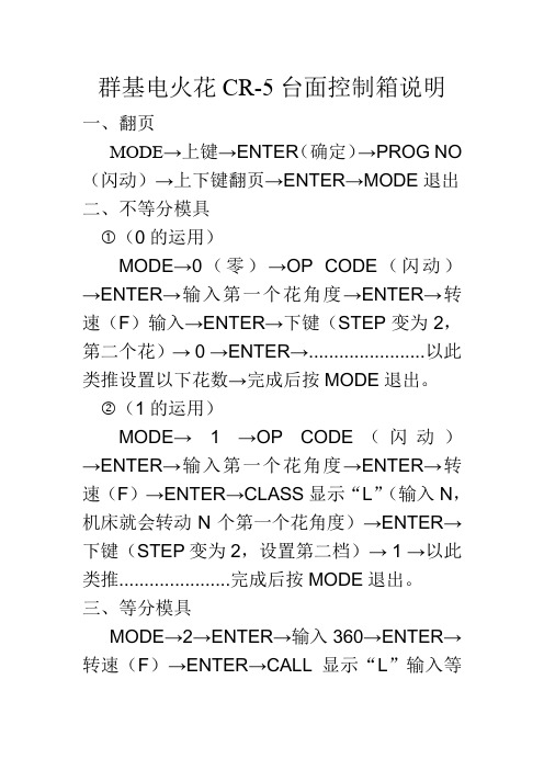
群基电火花CR-5台面控制箱说明一、翻页
MODE→上键→ENTER(确定)→PROG NO (闪动)→上下键翻页→ENTER→MODE退出二、不等分模具
①(0的运用)
MODE→0(零)→OP CODE(闪动)→ENTER→输入第一个花角度→ENTER→转速(F)输入→ENTER→下键(STEP变为2,第二个花)→ 0 →ENTER→.......................以此类推设置以下花数→完成后按MODE退出。
②(1的运用)
MODE→ 1 →OP CODE(闪动)→ENTER→输入第一个花角度→ENTER→转速(F)→ENTER→CLASS显示“L”(输入N,机床就会转动N个第一个花角度)→ENTER→下键(STEP变为2,设置第二档)→ 1 →以此类推......................完成后按MODE退出。
三、等分模具
MODE→2→ENTER→输入360→ENTER→转速(F)→ENTER→CALL显示“L”输入等
分数→ENTER→MODE退出。
四、台面的正反转
MODE→上键→长按小数点至DATA显示器熄灭→上下键至STEP为23时,DATA显示数为1时台面正转,为0时反转→MODE退出。
其它键的功能
START 转移花角度
ZERO 回零
HOME 机械回零
JOG 加/减小角度
STOP 停止
INS 增加档
DEL 删除档
CLR 清零。


eZ-FET lite Revision 1.10 User’s GuideApril 18, 2013 eZ-FET lite Revision 1.10 User’s Guide IntroductionThe eZ-FET lite is a low cost USB-based on-board emulation solution for MSP430 microcontrollers. It allows direct interfacing to a PC for easy programming, debugging,and evaluation and provides a USB-to-UART bridge for serial connection to the target microcontroller.The eZ-FET lite on-board emulation is supported by the MSP430 DLL and can be usedwith IAR Embedded Workbench™ for MSP430 Integrated Development Environment(IDE) or Code Composer Studio™ (CCS) IDE to write, download, and debug applications. Other tools supporting the eZ-FET on-board emulation are theMSP430Flasher, Elprotronic’s FET-Pro430, mspgcc and Energia.The debugger is unobtrusive, allowing the user to run an application at full speed withhardware breakpoints and single stepping available while consuming no extra hardware resources.Figure 1: eZ-FET lite on-board emulation (marked red) on MSP-EXP430F5529LPExperimenters Board1eZ-FET lite Revision 1.10 User’s Guide2 4/18/2013Features∙ USB debugging and programming interface featuring a driverless installation ∙ Application UART serial communication with up to 1MBaud ∙ Green and red LED for visual feedback ∙ Field-updateable firmware ∙Supports all MSP430 devicesHardware and Software RequirementsThe following hardware and software is required to use the eZ-FET on-board emulation∙ Personal computer with Windows O/S or Linux ∙ MSP430.DLL 3.3.0.6 or higher∙ Texas Instruments Code Composer Studio 5.4 or higher ∙ IAR Embedded Workbench 5.50 or higherReference Layout PCB OverviewFigure 2: eZ-FET Revision 1.10 reference layout overviewMicro-B USBEmulation MCUTarget Jumper BlockESD protection and power supplyDebug test pointseZ-FET lite Revision 1.10 User’s Guide Target ConnectorThe connection between the eZ-FET lite on-board emulation and the target microcontroller can be opened with the jumper array J101. This can be useful to connectto another target board, or when using a standalone debugger connected to the standard 14-pin header.The jumper array can also be used to measure the power consumption of the target application. For this intention, all connections except VCC must be opened, and a multimeter can used on the VCC jumper to measure the current of the target microcontrollerand its peripherals.The VCC jumper also must be opened if the target microcontroller is powered with an external power supply.Jumpers 11 and 13 connect the UART interface of the emulator to the target device pins.For higher baud rates it is recommended to also connect the handshake lines on jumpers 15 and 17 and make sure the target application code uses them appropriately.4/18/2013 3eZ-FET lite Revision 1.10 User’s GuideLED Signal PlayThe LED signal play is compatible with the MSP-FET430UIF and gives informationabout the internal status of the device.Using the UART backchannelThe UART backchannel has been developed such that it can operate fully independentfrom the debugger channel. When the eZ-FET lite is plugged into a Windows computer,two additional virtual COM ports will be shown in the Device Manager. The UART backchannel is accessible through the “MSP Application UART 1” virtual COM port.Any program that is able to generate serial data (e.g. a hyper terminal tool) can open thisport and send data to the target microcontroller. Please configure the virtual COM port touse 8 data bits, no parity and one stop bit (8-N-1).Figure 3: Device Manager with eZ-FET lite ports4 4/18/2013eZ-FET lite Revision 1.10 User’s GuideIn order to successfully communicate with the target microcontroller, the baud ratesetting on the computer side has to match the baud rate settings of the target microcontroller.SpecificationSupported DevicesTexas Instruments offers a wide range of MSP430 devices that are compatible with theeZ-FET. The following table shows the devices that have been tested.4/18/2013 5eZ-FET lite Revision 1.10 User’s GuideFAQQ: My MSP430 target device is not listed in the table of supported device. What should Ido?A: The table only lists the devices that have been tested with the eZ-FET lite at the timeof publication. There is a good chance that the eZ-FET works with the MSP430 target device. If you experience any problems, please contact us through the E2E forum on .Q: I cannot communicate with the target microcontroller through the UART backchannel.A: Several things need to be considered for a successful serial communication: matching baud rate settings on both computer and target side, the use of handshakelines (especially for higher baud rates), and the correct clock frequency of the target microcontroller. If the target microcontroller’s clock frequency does not match the valueused to calculate the UART settings, co mmunication won’t be successful. If in doubt, measure the baud rate on the TXD and RXD lines by sending alternating bit patternsfrom either side. A small deviation is acceptable, but if the error is large, send and transmit will most likely not be possible.Q: I would like to build my own tool using the eZ-FET lite. Where can I find more information?A: Please have a look into the official eZ-FET lite release package. The folders “Firmware” and “Production Setup” include both the binary files required t o program theeZ-FET lite microcontroller as well as a graphical environment that can be used to testthe eZ-FET lite hardware before programming it with production firmware.6 4/18/2013eZ-FET lite Revision 1.10 User’s Guide4/18/20137SchematiceZ-FET lite Revision 1.10 User’s Guide84/18/2013eZ-FET lite Revision 1.10 User’s Guide4/18/2013 9Bill of MaterialIte mQt yReferenc eManufacturerPart NumberValue1 1 C101 TDK C1005X5R1C474K 470n2 1 C102 TDK C1005X5R1C224K 220n3 1 C103 TDK C1005X5R1A104M 100n4 1 C104 Nichicon F931A106MAA 10u5 1 C105 TDK C1005X5R1A104M 100n6 1 C107 TDK C1005X5R1C224K 220n 7 1 C108 TDK C1005X5R1A104M 100n 8 1 C110 TDK C1005C0G1H100D 10p9 1 C111 TDK C1005C0G1H100D 10p 10 1 C112 TDK C1005X7R1H102K 1n 11 1 C113 TDK C1005X5R1A104M 100n 12 1 C114 TDK C1005X5R1A104M 100n 13 1 C121 TDK C1005X5R1A104M 100n 14 1 C122 TDK C1005C0G1H330J 33p 15 1 C123 TDK C1005C0G1H330J 33p16 1 IC101 TI TLV70036DSER TLV70036DSER 17 1 IC102 TI TPD4E004DRYR TPD4E004DRYR 18 1 J101 SullinsPEC09DAAN SBW/UART 19 1 J102 Hirose Electrical Co ZX62R-B-5P ZX62R-B-5P 20 1 LED101 Lite-On LTST-C190CKT Red 21 1 LED102 Lite-On LTST-C190GKT Green22 1 MSP101 TI MSP430F5528IRGC MSP430F5528IRGC23 1 Q101 Murata CSTCR4M00G15L99 PIEZO_CSTCR4M00G15L99 24 1 R101 Yageo RC0402FR-07470RL 470 25 1 R102 Yageo RC0402FR-07390RL 390 26 1 R103 Yageo RC0402JR-0727RL 27 27 1 R104 Yageo RC0402JR-0727RL 27 28 1 R105 Vishay Dale CRCW04021K40FKE D1k4 29 1 R106 Yageo RC0402FR-071ML 1M 30 1 R109 Yageo RC0402FR-0747KL 47k 31 1 R121 Yageo RC0402FR-07220KL 220k 32 1 R122 Yageo RC0402FR-07220KL 220k 33 1 R123 Yageo RC0402FR-071ML 33k 34 1 R124 Yageo RC0402FR-07240KL 240k 35 1 R125 Yageo RC0402FR-07150KL 150k 361R129YageoRC0402FR-0710RL10eZ-FET lite Revision 1.10 User’s Guide37 1 R130 Yageo RC0402FR-0710RL 1038 1 R131 Yageo RC0402FR-0710RL 1039 1 R132 Yageo RC0402FR-0710RL 1040 1 R133 Yageo RC0402FR-0710RL 1041 1 R134 Yageo RC0402FR-0710RL 1042 1 R135 Yageo RC0402FR-0710RL 10Known Issues1. USB suspend power down support not implemented in emulator firmware.Applies to DLL3.3.0.6.Revision History10 4/18/2013。

数字有线接收机DM500-C使用说明书操作手册:使用本机前,请仔细阅读此用户说明并保存好以供今后参考之用操作之前,请仔细阅读本说明书1.请认真阅读本手册。
2.请保留本手册。
3.请留意注意事项。
4.请按说明书指导操作。
5.不要将任何东西从机顶盒外壳上的通风孔往机内塞入或掉落进去,因为这样会使机顶盒受到严重的的损坏并有可能引起火灾。
6.切勿将机顶盒放在直射的阳光或热源附近。
7.机顶盒外壳上有通风孔,以防止机内温度过高,切勿以任何方式使这些通风孔受到阻塞,不使用机器时将电源拔掉。
8.切勿将装有水或液体的东西放在机顶盒上,万一有液体进入机内,应立即拔掉机顶盒的电源插头,并与经销商或维修中心联系。
9.不要拆下机顶盒的外壳,触碰机内的部件可能会受到电击或损坏机顶盒,如果要对机顶盒进行检修或调整,应请有经验的维修人员或经销商。
用户私自打开外壳而损坏不在保修范围之内。
10.长期不用或无人在家时请将电源拔掉,儿童或未成年人使用本机器或其他电器要有成年人陪同,以免发生意外。
11.如发现机器出现短路,冒烟、有异味,要立即断电,按第9条处理。
12.如违犯上述安全注意事项,有关责任本公司概不负责。
目录DM500-C (1)1. 主要特点 (4)2. 遥控器 (5)3. 前面板和后面板 (6)4. 系统的连接 (7)5. 主菜单 (8)5.1. 频道管理 (8)5.2. 频道搜索 (9)5.3. 系统设置 (11)5.4. CA(条件接收系统) (28)5.5. 界面指南 (29)6. 常见故障解决方法 (31)7. 技术指标 (32)1. 主要特点支援接收免费/付费数位电视节目采用功能强大的NEC芯片处理器符合DVB-C/MPEG-2标准存储多达1000套的数位电视节目和广播节目支持多家主流条件接收系统支持电子节目指南(EPG)支持多种搜索方式友好的用户操作界面支持节目编辑(删除/加锁/移动/重命名)、排序、喜爱分组功能附件◇使用说明书一本◇遥控器一个◇电源线一个◇A V连接线一条2. 遥控器1.静音键2.机顶盒待机开关3.~ 0~9数位键,输入所需菜单项目数字或输入所需观看的频道号码4.显示当前频道信息5.在菜单状态下回到播放节目状态,在无功能表时进入主功能表6.回看功能选择7.在有功能表时返回上级功能表,在播放节目时回到主菜单8.上下移动键,正常播放节目时也是频道+、-键9.左右移动键,正常播放节目时也是音量+、-键10.确定键11.广播节目及电视节目切换12.电子节目编辑13.执行喜爱、邮件、预定、音频等功能3. 前面板和后面板前面板④③②①1.STANDBY:按此键可使机顶盒处于待机状态。

S500 系列大屏幕温湿度计用户手册S500 系列温湿度记录仪用户手册S500-EX/TH/ET/DT-USB S500-EX/TH/ET/DT-RS4854.1 注意事项----------------------------------------------------------------------------------------------------4.2 常见故障----------------------------------------------------------------------------------------------------目 录第一章 产品介绍-------------------------------------------------------------------------11.1 产品特点----------------------------------------------------------------------------------------------------1.2 使用范围----------------------------------------------------------------------------------------------------1.3 性能参数----------------------------------------------------------------------------------------------------1.4 S500-EX/TH/ET/DT-USB记录仪外型说明------------------------------------------------------------1.5 S500-EX/TH/ET/DT-RS485记录仪外型说明--------------------------------------------------------- 1.6 LCD 显示屏符号说明-------------------------------------------------------------------------------------1.7 按键功能说明----------------------------------------------------------------------------------------------第二章 S500-EX/TH/ET/DT-USB软件使用指南-------------------------------------2.1 USB 驱动安装----------------------------------------------------------------------------------------------2.2 Logpro 软件的使用---------------------------------------------------------------------------------------第三章 S500-EX/TH/ET/DT-RS485软件使用指南----------------------------------3.1 ToMonitor 实时监测软件的使用方法-----------------------------------------------------------------3.2 查看上传的数据-------------------------------------------------------------------------------------------第四章 使用注意事项-------------------------------------------------------------------------------111234557510131616516第一章 产品介绍1.1 产品特点1.2 使用范围采用进口原厂封装校准一体式温湿度传感器内置容量存储器,可存储4.3万组温湿度数据测量温湿度精准度高温湿度数据和时间同时显示,按键操作简单方便内置声光报警,超限报警功能。
中厚板产品手册HEAVY PLATE PRODUCT MANUAL北京首钢股份有限公司B e i j i n g S h o u g a n gC o.,L t d.Chapter 1 Production Line Introduction第一章 产线简介首钢京唐公司中厚板产线拥有国内第一台400mm 板坯连铸机,拥有4300mm 和3500mm 两条生产线,常化炉、淬火炉、回火炉、车底炉等4座热处理炉,一条预处理产线及国内首条全流程复合板/卷自动化生产线。
产品规格覆盖厚度6~380mm、宽度1050~4050mm、钢板最大单重28.5吨。
首钢京唐公司中厚板产品涵盖12大系列+复合板、400多个品种,包括船舶及海洋工程用钢、管线钢、桥梁钢、容器板、风电钢、高建钢、工程机械用钢、耐磨钢、储罐钢、水电钢、结构用钢、模具钢。
产品广泛应用于能源、造船及海洋平台、机械制造、桥梁制造、交通运输、电力工程等行业。
Shougang Jingtang heavy plate production line is equipped with the domestic first 400mm continuous caster of slab, and two production lines of 3500mm and 4300mm, four heat treatment furnaces such as normalizing furnace, quenching furnace, tempering furnace and car bottom furnace, one pretreatment production line and the domestic first automatic production line of clad plate/coil. The product specifications cover the thickness of 6-380mm, the width of 1050-4050mm and the maximum unit weight of 28.5 tons.Shougang Jingtang Heavy plate category covers 12 major series and clad plate, more than 400 varieties,including shipbuilding and offshore steel, pipeline steel, bridge plate, vessel plate, wind power steel, high-risebuilding steel, high-strength steel, wear-resisitant steel, oil tank steel, hydropower steel, structure steel, and mouid steel. The products are widely applied to shipbuilding industry, energy industry (including pipeline project and petroleum chemistry industry), bridge building industry, transportation industry, manufacturing industry, power industry (including hydropower, wind power and heat power project) etc.1.1 生产流程示意图 Process Diagram1.1.1 炼钢系统Steel making system炼钢系统是一条低成本、高品质洁净钢生产线。
stalled motor overload.when the overload relay is tripped.These instructions do not purport to cover all details or variations in equipment not to provi met in connection with installation, operation or maintenance. Should further information be desired or should particular problems arise which are not covered sufficiently for the purchaser’s purpose, the matter should be referred to the DEH-40629 Installation Instructions For NEMA Size 4300/400-Line Combination Magnetic StartersCR307-CR308, CR310-CR311, CR387, CR390, CR407-CR408 CR410-CR415, CR487, CR490, CR492, CR494 SeriesRef.No Descriptioncircuits in the control wiring.PRINCIPAL RENEWAL PARTSFigure 3 — ABB Inc. 305 Gregson Drive Cary, NC 27511.—We reserve the right to make technical changes or modify the contents of this document without prior notice. With regard to purchase orders, the agreed particulars shall prevail. ABB Inc. does not accept any responsibility whatsoever for potential errors or possible lack of information in this document.We reserve all rights in this document and in the subject matter and illustrations contained therein. Any reproduction or utilization of its contents – in whole or in parts – is forbidden without prior written consent of ABB Inc. Copyright© 2019 ABB All rights reserved— GE is a trademark of GE. Manufactured by ABB Inc. under license from GE. 1S Q C 912011M 0201 D E H -。
l4K604:4:4supportl HDR10,Deep Color,and3D videol Dolby®TrueHD,Dolby Atmos®,DTS HD®,and uncompressed7.1linear PCM audiol HDBaseT®compatibilityl HDCP2.2compliancel HDMI®input(DVI and Dual-Mode DisplayPort™interface compatible)l DM8G+®output for connection to a DM®switcher or receiver via a single CAT5e(or higher)twisted pair cablel Transmission distance up to330ft(100m)for resolutions up to UHD and4K using DM Ultra cablel Transmission distance up to330ft(100m)for1080p, WUXGA,and2K using DM8G®cable or CAT5el Transmission distance up to230ft(70m)for UHD and4K using DM8G cable or up to165ft(50m)using CAT5el Device control via CEC,IR,and RS-232l Powered via the DM connection or optional power pack(sold separately)l Versatile mounting options including1-gang electrical box, surface mounting,and attachment to rack raill Surface-mount bracket includedl Available in black or white finish The DM-TX-4KZ-100-C-1G wall plate transmitter provides a cost-effective solution for a single AV source as part of a complete Crestron®DigitalMedia™system.Functioning as a DM8G+®transmitter and control interface,the DM-TX-4KZ-100-C-1G provides an HDMI®input and a DM 8G+output as well as IR and RS-232control ports.The DM-TX-4KZ-100-C-1G incorporates DM4KZ technology,which enables4K604:4:4and HDR(High Dynamic Range)support.1The DM-TX-4KZ-100-C-1G is also compatible with HDBaseT®technology. The DM-TX-4KZ-100-C-1G provides a1-gang mountable design and is available in black(DM-TX-4KZ-100-C-1G-B-T)and white (DM-TX-4KZ-100-C-1G-W-T).4K604:4:4and HDR SupportDM4KZ technology uses VESA®Display Stream Compression (DSC)to handle the extreme bandwidth requirement of resolutions beyond4K304:4:4and4K604:2:0.DSC is a lightweight,line-based2:1compression standard that delivers visually lossless performance for4K604:4:4and HDR signals.1 DSC is applied only to4K604:4:4and HDR input signals. All other signals are transported uncompressed.An existing4K DigitalMedia system can be upgraded to handle 4K604:4:4and HDR video with the installation of DM4KZ cards,transmitters,and receivers.The upgrade can be accomplished without the need to replace wiring or switchers. The DM-TX-4KZ-100-C-1G can replace a DM-TX-4K-100-C-1G in an existing installation(additional programming may be required).DM8G+TechnologyEngineered for ultra high-bandwidth and ultimate scalability, Crestron DM8G+technology transports high-definition video, audio,power,Ethernet,and control signals over twisted pair copper wire.Uncompressed Full HD1080p,WUXGA,and2K signals are supported at distances up to330ft(100m)using Crestron DM®Ultra cable,Crestron DM8G®cable,or third-party CAT5e(or higher).Higher resolution signals up to UHD and4K are supported at distances up to330ft(100m)using DM Ultra cable,230ft(70m)using DM8G cable,or165ft (50 m)using third-party CAT5e(or higher).2HDBaseT CompatibilityDM8G+technology is designed using HDBaseT Alliance specifications,ensuring interoperability with other HDBaseT certified products.Via the DM8G+output,the DM-TX-4KZ-100-C-1G can be connected directly to a third-party HDBaseT compliant receiver or display device without requiring a DM receiver.Multimedia Computer/AV InterfaceA single HDMI input port is provided on the DM-TX-4KZ-100-C-1G for connection to a laptop computer,mobile device,or other AV source.3A single CAT5e(or higher)cable connects the DM-TX-4KZ-100-C-1G to a DM switcher or receiver or to an HDBaseT device.Video,audio,control,networking,and power signals are transported through one RJ-45connection.2,4,5When used with a DM switcher,multiple DM-TX-4KZ-100-C-1G devices can be installed,enabling several AV input signals at different locations to be transmitted to multiple displays throughout a room or larger facility.When used with a single DM 8G+receiver/room controller,the DM-TX-4KZ-100-C-1G extends an AV signal to a single display.Device ControlThe DM-TX-4KZ-100-C-1G includes built-in IR and RS-232control ports to enable programmable control of the connected source device via a control system.6When connected to a control system,the DM-TX-4KZ-100-C-1G also provides agateway for controlling the AV source through CEC (Consumer Electronics Control)over the HDMI input,potentiallyeliminating the need for a dedicated serial cable or IR emitter.Pass-through mode for RS-232and CEC is also supported.For additional information,refer to Online Help Answer ID 1000497on the Crestron website ( ).Versatile Mounting OptionsThe DM-TX-4KZ-100-C-1G is designed to be mounted into a 1-gang electrical box or plaster ring (not included).Standard gang-box mounting enables installation adjacent to an Ethernet jack (Crestron MP-WP183or equivalent).7Using the included mounting bracket,the DM-TX-4KZ-100-C-1G can also be attached to a suitable flat surface such as the underside of a table.As an additional mounting option,the DM-TX-4KZ-100-C-1G can be attached to a single rackrail.Power via the DM connection can be used to power the DM-TX-4KZ-100-C-1G.The device can also be powered using the optional PW-2407WUL wall mount power pack (sold separately).For additional design tools and reference documents,refer to the DigitalMedia resources web page at /dmresources .Specifications Maximum Cable Lengths The following table lists resolutions and corresponding maximum cable lengths.VideoInput SignalTypesHDMI with HDR10,Deep Color,3D,and 4K604:4:4support (DVI and Dual-Mode DisplayPort™interface compatible)3Output SignalTypesDM 8G+and HDBaseT with HDR10,Deep Color,3D,and 4K604:4:4support CopyProtection HDCP 2.2MaximumResolutionsThe following table lists common resolutions.AudioInput Signal Types HDMI(Dual-Mode DisplayPort interface compatible)3Output SignalTypesDM8G+,HDBaseTFormats Dolby Digital®,Dolby Digital EX,Dolby DigitalPlus,Dolby®TrueHD,Dolby Atmos®,DTS®,DTS ES,DTS96/24,DTS HD®High Res,DTSHD Master Audio™,LPCM up to8channels CommunicationsRS-2322-way device control and monitoring up to115.2k baud with software handshaking viacontrol systemIR/Serial1-way device control via infrared up to1.1MHzor serial TTL/RS-232(0-5V)up to19.2k baudvia control systemDigitalMedia DM8G+,HDCP2.2,EDID,CEC,PoDM HDBaseT HDCP2.2,EDID,CEC,PoEHDMI HDCP2.2,EDID,CEC Connectors,FrontHDMI IN(1)19-pin Type A connector,female;HDMI digital video/audio input(DVI and Dual-Mode DisplayPort interfacecompatible)3IR OUT(1)2-pin3.5mm detachable terminal block;IR/serial port;2IR output up to1.1MHz;1-way serial TTL/RS-232(0-5V)up to19200baudCOM(1)3-pin3.5mm detachable terminal block;Bidirectional RS-232port;2Up to115.2k baud,software handshakingsupportConnectors,RearG(1)6-32screw;Chassis ground lugDM OUT(1)8-pin RJ-45female,shielded;DM8G+output,HDBaseT standard compliant;PoDM PD(Powered Device)port(HDBaseTPoE compatible);4,5Connects to the DM8G+input of a DMswitcher,receiver,or other DM device or to anHDBaseT device via CAT5e,Crestron DM-CBL-8G,or Crestron DM-CBL-ULTRA cable2 24VDC0.75A(1)2-pin3.5mm detachable terminal block;24VDC power input;PW-2407WUL power pack sold separately IndicatorsPOWER(1)Green LED,indicates operating powersupplied via PoDM,HDBaseT PoE,or localpower packVIDEO(1)Green LED,indicates video signal presenceat the HDMI inputDM OUT (rear)(2)LEDs,green LEDindicates DM link status,amber LED indicatesvideo and HDCP signal presencePowerPower over DM(PoDM)IEEE802.3at Type1Class3(12.95W) compliantPoDM PD,capable of being powered by PoDM PSE(Power Sourcing Equipment)4Power over HDBaseT IEEE802.3at Type1Class3(12.95W) compliantHDBaseT PoE PD,capable of being powered by HDBaseT PoE PSE5Power Pack (Optional)Input:100-240VAC,50/60Hz Output:0.75A@24VDCModel:PW-2407WUL(sold separately)Power Consumption With PoDM or HDBaseT PoE:5.43W typical3.25W idleWith24VDC:5.55W typical3.31W idleEnvironmentalTemperature32°to95°F(0°to35°C) Humidity10%to90%RH(non-condensing)Heat Dissipation With PoDM or HDBaseT PoE:18.53BTU/hr typical11.09BTU/hr idleWith24VDC:18.94BTU/hr typical11.29BTU/hr idleEnclosureConstruction Metal with white or black polycarbonate labeloverlay on front panelFlush Wall Mount Mounts in1-gang2-1/8in.deep electrical box or plaster ring(not included),decorator style faceplate sold separatelySurfaceMountSurface-mount bracket includedRack Mount Attaches to a single19-inch EIA rack rail DimensionsHeight 4.11in.(105mm)Width 1.72in.(44mm)Depth 2.20in.(56mm)Weight8.0oz(227g)ComplianceETL(Intertek),CE,IC,FCC Part15Class B digital deviceModelsDM-TX-4KZ-100-C-1G-B-TDigitalMedia4K604:4:4Wall Plate Transmitter,Black DM-TX-4KZ-100-C-1G-W-TDigitalMedia4K604:4:4Wall Plate Transmitter,White Available AccessoriesPW-2407WULWall Mount Power Pack,24VDC,0.75A,Flying Leads, UniversalFP-G1-B-T(DM-TX-4KZ-100-C-1G-B-T only)Decorator Style Faceplate,1-Gang,Black TexturedFP-G1-W-T(DM-TX-4KZ-100-C-1G-W-T only)Decorator Style Faceplate,1-Gang,White TexturedDM-PSU-ULTRA-MIDSPANDigitalMedia Ultra Midspan PoDM++InjectorDM-CBL-ULTRA-PC-1.5DigitalMedia Ultra Patch Cable,1.5ft(0.45m)DM-CBL-ULTRA-PC-3DigitalMedia Ultra Patch Cable,3ft(0.9m)DM-CBL-ULTRA-PC-5DigitalMedia Ultra Patch Cable,5ft(1.5m)DM-CBL-ULTRA-PC-7DigitalMedia Ultra Patch Cable,7ft(2.1m)DM-CBL-ULTRA-PC-10DigitalMedia Ultra Patch Cable,10ft(3m)DM-CBL-ULTRA-PC-15DigitalMedia Ultra Patch Cable,15ft(4.5m)DM-CBL-ULTRA-PC-20DigitalMedia Ultra Patch Cable,20ft(6m)DM-CBL-ULTRA-PC-50DigitalMedia Ultra Patch Cable,50ft(15m)DM-CONN-ULTRA-RECP-20DigitalMedia Ultra Keystone RJ-45Jack,20-Pack with Termination ToolDM-CONN-ULTRA-RECP-50DigitalMedia Ultra Keystone RJ-45Jack,50-Pack with Termination ToolDM-CBL-ULTRA-NP-SP500DigitalMedia Ultra Cable,Non-Plenum Type CMR,500ft SpoolDM-CBL-ULTRA-NP-SP1000DigitalMedia Ultra Cable,Non-Plenum Type CMR,1000ft SpoolDM-CBL-ULTRA-P-SP500DigitalMedia Ultra Cable,Plenum Type CMP,500ft Spool DM-CBL-ULTRA-P-SP1000DigitalMedia Ultra Cable,Plenum Type CMP,1000ft Spool DM-CBL-ULTRA-LSZH-SP500DigitalMedia Ultra Cable,Low Smoke Zero Halogen,500ft Spool(Available only inEurope)DM-CBL-ULTRA-LSZH-SP1000DigitalMedia Ultra Cable,Low Smoke Zero Halogen,1000ft Spool(Available only in Europe)DM-CONN-20Connectors for DM-CBL-ULTRA DigitalMedia Ultra Cable,20-PackDM-CBL-8G-NP-SP500DigitalMedia8G™Cable,Non-Plenum,500ft SpoolDM-CBL-8G-NP-SP1000DigitalMedia8G Cable,Non-Plenum,1000ft SpoolDM-CBL-8G-P-SP500DigitalMedia8G Cable,Plenum,500ft SpoolDM-CBL-8G-P-SP1000DigitalMedia8G Cable,Plenum,1000ft SpoolDM-8G-CONN-WG-100Connectors with Wire Guide for DM-CBL-8G DigitalMedia8G Cable,100-PackDM-8G-CRIMPCrimping Tool for DM-8G-CONNDM-8G-CONN-WGConnectors with Wire Guide for DM-CBL-8G DigitalMedia8G CableDM-8G-CRIMP-WGCrimping Tool for DM-8G-CONN-WGCBL-HD-6Crestron Certified HDMI Interface Cable,18Gbps,6ft(1.8m)CBL-HD-12Crestron®Certified HDMI Interface Cable,18Gbps,12ft(1.8m)IRP2IR Emitter Probe with Terminal Block ConnectorMP-WP183-BMedia Presentation Wall Plate-Ethernet,BlackMP-WP183-WMedia Presentation Wall Plate-Ethernet,WhiteNotes:1.4K604:4:4performance and HDR support require the use of HDMI cablesand couplers with a minimum TMDS bandwidth of18Gbps.If4K604:2:0or 4K304:4:4performance is acceptable,cables and couplers with a minimum bandwidth of10.2Gbps can be used.Bandwidth loss is cumulative;therefore,performance may be reduced when inserting multiple cablesand couplers inline.2.The maximum cable length for DM8G+or HDBaseT transmission isdependent upon the type of cable and resolution of the video signal.Refer to the Maximum Cable Lengths table for information.Crestron legacycable models DM-CBL and DM-CBL-D support the same resolutions and cable lengths as CAT5e.Shielded cable and connectors are recommended to safeguard against unpredictable environmental electrical noise thatmay impact performance at resolutions above1080p.Refer to theCrestron DigitalMedia System Design Guide(Doc.4546)for additionalguidelines.DM8G+technology is compatible with the HDBaseT Alliancespecifications for connecting to HDBaseT compliant equipment.All wireand cables are sold separately.3.The HDMI input requires an appropriate adapter or interface cable toaccommodate a DVI or Dual-Mode DisplayPort signal.CBL-HD-DVIinterface cables are available separately.4.In order for the DM-TX-4KZ-100-C-1-G to receive PoDM(Power overDigitalMedia),the device must connect to a DM switcher or otherequipment that has a PoDM PSE port.Wiring that connects to a PoDMPSE port is for intrabuilding use only.5.In order for the DM-TX-4KZ-100-C-1-G to receive HDBaseT PoE,the devicemust connect to equipment that has an HDBaseT PoE PSE port.Wiringthat connects to an HDBaseT PoE PSE port is for intrabuilding use only. 6.The IR and RS-232(COM)ports are enabled only when the DM-TX-4KZ-100-C-1G connects to an Ethernet-enabled DM receiver or switcher that is addressable from a Crestron control system.7.The DM-TX-4KZ-100-C-1G does not include an Ethernet port.LocalEthernet connectivity for external devices requires an MP-WP183orequivalent Ethernet jack with a dedicated LAN connection.This product may be purchased from select authorized Crestron dealers and distributors.To find a dealer or distributor,please contact the Crestron sales representative for your area.A list of sales representatives is available online at /How-To-Buy/Find-a-Representative or by calling855-263-8754.This product is covered under the Crestron standard limited warranty.Refer to /warranty for full details.The specific patents that cover Crestron products are listed online at.Certain Crestron products contain open source software.For specific information,please visit /opensource.Crestron,the Crestron logo,DigitalMedia,DigitalMedia8G,DigitalMedia8G+, DM,DM8G,and DM8G+are either trademarks or registered trademarks of Crestron Electronics,Inc.in the United States and/or other countries.Dolby, Dolby Atmos,and Dolby Digital are either trademarks or registered trademarks of Dolby Laboratories in the United States and/or other countries.DTS,DTS HD, and DTS HD Master Audio are either trademarks or registered trademarks of DTS,Inc.in the United States and/or other countries.HDBaseT and the HDBaseT Alliance logo are either trademarks or registered trademarks of the HDBaseT Alliance in the United States and/or other countries.HDMI and the HDMI logo are either trademarks or registered trademarks of HDMI Licensing LLC in the United States and/or other countries.DisplayPort and VESA are either trademarks or registered trademarks of Video Electronics Standards Association in the United States and/or other countries.Other trademarks, registered trademarks,and trade names may be used in this document to refer to either the entities claiming the marks and names or their products.Crestron disclaims any proprietary interest in the marks and names of others.Crestron is not responsible for errors in typography or photography.Specifications are subject to change without notice.©2020Crestron Electronics,Inc.Rev07/09/20。
CR5100D型设备使用说明
可解码CR50XX系列视频服务器的视频,包括CR5000L,CM500PT,CR5024C等设备等;D1/CIF自适应。
音视频同解。
单路模拟输出,16路循环解码,可外接键盘。
1.1设备接口定义
1.1.1前后面板
1.1.2接口定义
1.2设备快速配置
解码器的常规使用涉及一下几个方面:(1)设备联网和IP配置;(2)解码器加入中心平台(3)编解码绑定,输出显示视频。
1.2.1修改设备IP信息
设备默认出厂的设置:
修改设备的IP信息,可以用“设备搜索
器”或者“管理器”软件都可以修改。
设备搜索器搜索到设备之后,双击信息
栏,进入设置页面,其中“网络设置”部分;
可设置动态获取或者静态分配。
A:使用静态分配IP
B:使用DHCP自动获取IP
C:使用PPPoE拨号获取IP;拨号的帐户
和密码需要设置。
注意:
Ip地址具体如何分配参考设备使
用地的网络环境或者咨询当地网管或网络供
应商。
修改设备的IP信息,需要重启之后才
生效;
1.2.2设置解码器设备加入中心服务器平台
a)设备搜索器中设置
搜索到设备之后,双击进入配置页面,
选中“自动登陆中心管理服务器”;填写中
心服务器的IP和接入端口号(默认8888),
流类型至少选一,或者2个都选。
中心服务器平台的IP和端口,必须是
真实有效,和实际的中心管理服务器平台一
致,否则加入不了中心平台。
b)管理器中设置
管理器登陆设备(默认:admin/空/设备的IP/3645),点击资源树根节点“Encoder”,或者是“编码站点”之类,在右侧的“网络”属性页面中修改。
1.2.3编解码绑定,模拟视频输出
解码器的视频输出接上电视墙等模拟视频显示设备。
管理器登陆设备(或者登陆中心平台,此时设备需在平台中),资源中有”视频输出”资源或“VedioOut”。
点击,右侧视频绑定页面中,可以设定需要解码输出到电视墙的视频源。
点击“添加”按钮,在“添加轮跳信息”框中,点击“添加新的编码站点”
按钮。
(如果管理器通过登陆中心服务器来配置其中的解码器的视频绑定信息,则此处无需添加编码站点,可以直接在界面中选择需要解码的视频。
)
最多可以添加16条绑
定关系,在16个视频
之间循环解码显示
如果登陆的是中心平
台,此框中会列出所
有编码器的视频资源
解码器登陆编码
器的连接信息
添加要解码
的视频信息
提示:
直连/转发:视频解码,需解码器主动连接编码器,申请获取视频。
连接的路径有2种:直连和转发。
直连:解码器直接向编码申请获取视频;转发:解码器的视频由中心服务器转发而来,不是直接由编码器发来!
轮跳显示:解码器做到可解码16路视频,在16中轮跳显示;每个视频轮跳的时间默认10秒,可改。
在解码多路视频的情况下,也可以固定显示其中之一,而不用轮跳模式。
1.2.4输出诊断
1.3设备性能参数表
1.4子型号对照表。