8B U 6 (37P)编辑
- 格式:ppt
- 大小:2.90 MB
- 文档页数:57

系列直流电子负载编程手册REV 002024.02版权优利德中国科技有限公司商标信息UNI-T是优利德中国科技有限公司的注册商标。
文档编号声明●本公司产品受中国及其它国家和地区的专利(包括已取得的和正在申请的专利)保护。
●本公司保留改变规格及价格的权利。
●本手册提供的信息取代以往出版的所有资料。
●本手册提供的信息如有变更,恕不另行通知。
●对于本手册可能包含的错误,或因手册所提供的信息及演绎的功能以及因使用本手册而导致的任何偶然或继发的损失,UNI-T概不负责。
●未经UNI-T事先书面许可,不得影印、复制或改编本手册的任何部分。
●产品认证UNI-T认证本产品符合中国国家产品标准和行业产品标准及ISO9001:2008标准和ISO14001:2004标准,并进一步认证本产品符合其它国际标准组织成员的相关标准。
本章主要涵盖以下内容:命令解析器——了解命令解析器的一些规则。
命令语法——命令行的书写规则。
查询语法——查询命令的书写规则。
查询响应——查询响应的格式。
命令参考本章节提供了仪器使用的所有的SCPI命令,通过这些SCPI命令,可以完全控制仪器所有功能。
1.1命令串解析主机可以发送一串命令给仪器,仪器命令解析器在捕捉到结束符(\n)或输入缓冲区溢出后开始解析。
例如:合法的命令串:AAA:BBB CCC;DDD EEE;:FFF仪器命令解析器负责所有命令解析和执行,在编写程序前您必须首先对其解析规则有所了解。
1.1.1命令解析规则命令解析器只对ASCII 码数据进行解析和响应。
SCPI 命令串必须以NL(‘\n’ ASCII 0x0A)为结束符,命令解析器在收到结束符后或缓冲区溢出才开始执行命令串。
如果指令握手打开,命令解析器在每接收到一个字符后,立即将该字符回送给主机,主机只有接收到这个回送字符后才能继续发送下一个字符。
命令解析器在解析到错误后,立即终止解析,当前指令作废。
命令解析器在解析到查询命令后,终止本次命令串解析,其后字符串被忽略。

UT8806台式数字多用表数据手册REV 02023.11⏹ 4.3”TFT-LCD,显示分辨率480×272⏹6½位读数⏹高达10,000 rdgs/s的测量速度⏹真有效值交流电压和电流测量⏹32Gb Nand Flash 总容量,海量存储仪器设置文件和数据文件⏹内置热电偶冷端补偿⏹支持标准 SCPI 远程控制命令、上位机软件、兼容最新主流万用表命令集⏹支持双显示、中英文菜单,内置帮助系统,方便信息获取⏹配置接口:USB Host,USB Device,LAN,RS-232C,GPIB⏹测量数据及设置可通过 VXI-11,USBTMC, U 盘导入或者导出,以方便用户修改、查看、备份支持标准SCPI 远程控制命令UT8806 6½位双显示数字万用表,拥有出众的读数速率和精确度,是为满足客户多功能,高精度,自动测量要求而设计的一款产品。
基本测量功能:直流电压测量:200mV,2V,20V,200V,1000V直流电流测量:2μA, 20μA ,200μA,2mA,20mA,200mA,2A,10A交流电压测量(RMS):200mV,2V,20V,200V,750V交流电流测量(RMS):200μA,2mA,20mA,200mA,2A,10A电阻测量(2,4线)20Ω,200Ω,2kΩ,20kΩ,200kΩ,2MΩ,10MΩ,100MΩ,1GΩ电容测量:2nF,20nF,200nF,2μF,20μF,200μF,2mF,20mF, 100mF连通性测试:固定2kΩ二极体测试:0V至4V频率测试:3Hz至1MHz周期测量:1μs至0.05s温度测量:支持热电偶和热电阻传感器数学运算功能:最大值,最小值,平均值,标准差,相对测量,条形表,直方图,趋势图,dB/ dBm,Pass/Fail等人性化设计:图形化的用户界面,操作简单方便;更有帮助系统,方便信息获取;支持中英文菜单;双窗口显示功能;支持 U 盘和本地存储,便于文件管理。

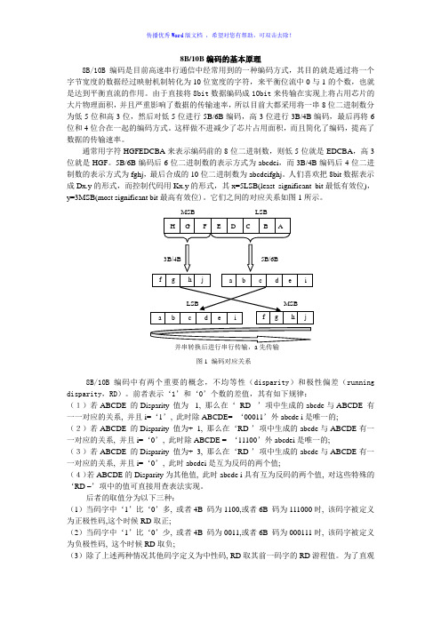
8B/10B 编码的基本原理8B/10B 编码是目前高速串行通信中经常用到的一种编码方式,其目的就是通过将一个字节宽度的数据经过映射机制转化为10位宽度的字符,来平衡位流中0与1的个数,也就是达到平衡直流的作用。
由于直接将8bit 数据编码成10bit 来传输在实现上将占用芯片的大片物理面积,并且严重影响了数据的传输速率,所以目前大都采用将一串8位二进制数分为低5位和高3位,然后对低5位进行5B/6B 编码,高3位进行3B/4B 编码,最后再将6位和4位合在一起的编码方式。
这样做不进减少了芯片占用面积,而且简化了编码,提高了数据的传输速率。
通常用字符HGFEDCBA 来表示编码前的8位二进制数,则低5位就是EDCBA ,高3位就是HGF 。
5B/6B 编码后6位二进制数的表示方式为abcdei ,而3B/4B 编码后4位二进制数的表示方式为fghj ,最后合成的10位二进制数为abcdeifghj 。
人们喜欢把8bit 数据表示成Dx.y 的形式,而控制代码用Kx.y 的形式,其x=5LSB(least significant bit 最低有效位),y=3MSB(most significant bit 最高有效位)。
它们之间的对应关系如图1所示。
8B/10B 编码中有两个重要的概念,不均等性(disparity )和极性偏差(running disparity ,RD )。
前者表示‘1’和‘0’个数的差值,其有如下规律:(1)若ABCDE 的Disparity 值为- 1, 那么在‘ RD- ’项中生成的abcde 与ABCDE 有一一对应的关系, 并且i=‘1’, 此时除ABCDE= ‘00011’外abcde i 是唯一的;(2)若ABCDE 的Disparity 值为+ 1, 那么在‘RD-’项中生成的abcde 与ABCDE 有一一对应的关系, 并且i=‘0’, 此时除ABCDE = ‘11100’外abcdei 是唯一的;(3)若ABCDE 的Disparity 值为+ 3, 那么在‘RD-’项中生成的abcde 与ABCDE 有一一对应的关系, 并且i=‘0’, 此时abcdei 是互为反码的两个值; (4)若ABCDE 的Disparity 为其他值, 此时abcde i 具有互为反码的两个值, 对这些特殊的‘RD –’项中的值可直接用查表法实现。

操作供给系统313910B用于高粘度密封剂和粘合剂涂料介质的不加热批量输送。
不可用于危险性场所。
L20c 2 英寸单立柱升降机20 升(5 加仑)尺寸最大空气入口压力 100 psi (0.7 MPa, 7 bar)S20 3 英寸单立柱20 升(5 加仑)尺寸125 psi (0.9 MPa, 9 bar) 最大空气入口压力D60 3 英寸双立柱。
60 升(16 加仑)尺寸,30 升(8 加仑), 20 升(5 加仑)尺寸最大空气入口压力 150 psi (1.0 MPa, 10bar)D200 3 英寸双立柱200 升(55 加仑),115 升(30 加仑), 60 升(16 加仑)尺寸,30 升(8 加仑), 20 升(5 加仑)尺寸150 psi (1.0 MPa, 10 bar) 最大空气入口压力D200S 6.5 英寸双立柱55 加仑(200 升),30 加仑(115 升)尺寸125 psi (0.9 MPa, 9 bar) 最大空气入口压力有关的型号资料和核准情况,请参见第6页。
美国专利正在审理中Graco 控制系统结构电气部件都已列入 Intertek 产品目录。
妥善保存说明文件。
D200ti10429a型号 CM14BA目录相关手册 . . . . . . . . . . . . . . . . . . 3译文 . . . . . . . . . . . . . . . . . . . 3警告 . . . . . . . . . . . . . . . . . . . . 4型号 . . . . . . . . . . . . . . . . . . . . 6部件识别 . . . . . . . . . . . . . . . . . .10 D200 3 英寸和 D200s 6.5 英寸双立柱 . . . .10 S20 3 英寸单立柱和 D60 3 英寸双立柱 . . .11 L20c 2 英寸升降机 . . . . . . . . . . . .13 L20c 2 英寸气流控制器 . . . . . . . . . .14安装 . . . . . . . . . . . . . . . . . . . .15基本信息 . . . . . . . . . . . . . . . . .15位置 . . . . . . . . . . . . . . . . . . .15接地 . . . . . . . . . . . . . . . . . . .15机械设置 . . . . . . . . . . . . . . . . .16将远程 DataTrak 连接到电源 . . . . . . . .16固定和调整料桶液位低/空料传感器 . . . . .17灯塔附件 . . . . . . . . . . . . . . . . .17固定料桶止挡 . . . . . . . . . . . . . . .18供给系统操作 . . . . . . . . . . . . . . . .19泄压步骤 . . . . . . . . . . . . . . . . .19使用前冲洗设备 . . . . . . . . . . . . . .19起动和调整立柱 . . . . . . . . . . . . . .19起动和调整泵 . . . . . . . . . . . . . . .21更换料桶 . . . . . . . . . . . . . . . . .21泵的停机和维护 . . . . . . . . . . . . . .22更换喉管密封 . . . . . . . . . . . . . . .22远程 DataTrak 设置 . . . . . . . . . . . .23远程 DataTrak 控制器和指示灯 . . . . . . . .24远程 DataTrak 操作 . . . . . . . . . . . . .25起动 . . . . . . . . . . . . . . . . . . .25运行模式 . . . . . . . . . . . . . . . . .25填料模式 . . . . . . . . . . . . . . . . .26设置模式 . . . . . . . . . . . . . . . . .26诊断模式 . . . . . . . . . . . . . . . . .29尺寸 . . . . . . . . . . . . . . . . . . . .34示意图 . . . . . . . . . . . . . . . . . . .36远程 DataTrak,灯塔,料桶液位低/空料传感器 36D200S、D200、S20 和 D60 供给系统 . . . . . .37起动和调整立柱 . . . . . . . . . . . . . .37起动和调整泵 . . . . . . . . . . . . . . .38更换料桶 . . . . . . . . . . . . . . . . .38远程 DataTrak 操作 . . . . . . . . . . . .38L20c 供给系统 . . . . . . . . . . . . . . . 39起动和调整立柱 . . . . . . . . . . . . . 39起动和调整泵 . . . . . . . . . . . . . . 40更换料桶 . . . . . . . . . . . . . . . . 40技术数据 . . . . . . . . . . . . . . . . . . 41 Graco Standard Warranty . . . . . . . . . . 42 Graco Information . . . . . . . . . . . . . 422313910B相关手册313910B 3相关手册各部件手册(中文):译文本手册有下列语言版本。

UNI-T 使用说明书UTL8200/8500电子负载系列通信协议(SCPI)-REV.32022年4月UNI-T TECHNOLOGY(China) Co.,LtUTL8200/8500电子负载系列通信协议UNI-T保证和声明版权2019 优利德科技(中国)股份有限公司商标信息UNI-T是优利德科技(中国)股份有限公司的注册商标。
声明⚫本公司产品受中国及其它国家和地区的专利(包括已取得的和正在申请的专利)保护。
⚫本公司保留改变规格及价格的权利。
⚫本手册提供的信息取代以往出版的所有资料。
⚫本手册提供的信息如有变更,恕不另行通知。
⚫对于本手册可能包含的错误,或因手册所提供的信息及演绎的功能以及因使用本手册而导致的任何偶然或继发的损失,UNI-T概不负责。
⚫未经UNI-T事先书面许可,不得影印、复制或改编本手册的任何部分。
产品认证UNI-T认证本产品符合中国国家产品标准和行业产品标准及ISO9001:2015标准和ISO14001:2015标准,并进一步认证本产品符合其它国际标准组织成员的相关标准。
联系我们如您在使用此产品或本手册的过程中有任何问题或需求,可与UNI-T联系:电子邮箱:网址:UNI-T SCPI 命令概述协议所有的下行编程数据及上行返回数据,均采用 ASCII 字符表示,以换行符<LF>(0x0A)或回车符<CR>(0x0D)确定一帧数据的结束。
协议支持以下几种数据格式:1)<NR1>,整数,例如123.2)<NR2>,含有小数点的数字,例如1.234.3)<NR3>,用科学计数法表示的数字,例如1.23E+2.4)<Nrf>,扩展格式,包括<NR1>,<NR2>,<NR3>, 例如123、0.123、1.23E2.5)<Nrf+>,包括<Nrf>,MIN,MAX,例如123、0.123、1.23E2、MIN、MAX。
114-93037Issue 1, April 20168-Position Cat6/6A Shielded Slim-Line Modular Plug1. IntroductionThis specification covers the requirements for application of Category 6/6A shielded slim-line modular plugconnectors. These requirements are applicable to hand or automatic machine terminating tools. Round, twisted-pair, shielded cables with 24-26 AWG stranded conductors are approved for use with these connectors. The insulated conductor outside diameter must be between 0,89 and 1,09 [.035 and .043], and a cable jacket outside diameter between 4,7 and 7,0 [.185 and .276].When corresponding with CommScope ®personnel, use the terminology provided in this document to facilitate your inquiries for information. Components of the slim-line modular plug connectors are provided in Figure 1. Note: All numerical values are in metric units [with U.S. customary units in brackets]. Dimensions are in millimeters [and inches]. Figures and illustrations are for identification only and are not to scale.Figure 1. Slim-Line Modular Plug ComponentsBoot/strain reliefShieldSubassy 8 positionContact no. 1Contact no. 8HousingOptional color clip© 2016 CommScope, Inc.All rights reservedThis product is covered by one or more U.S.patents or their foreign equivalents. For patents, see/ProductPatent/ProductPatent.aspxPage 1 of 11114-93037Application Specification 2. How to Contact Us•To find out more about CommScope® products, visit us on the web at /•For technical assistance:-Within the United States, contact your local account representative or technical support at 1-800-344-0223. Outside the United States, contact your local account representative orPartnerPRO™ Network Partner.-Within the United States, report any missing/damaged parts or any other issues to CommScope Customer Claims at 1-866-539-2795 *****************************.OutsidetheUnitedStates, contact your local account representative or PartnerPRO Network Partner.3. Reference Material3.1 Revision SummaryThis paragraph is reserved for a revision summary of changes and additions made to this specification. The following changes were made for this revision:•Initial release3.2 Customer AssistancePart numbers 2111981 and 2111984 are representative numbers of 8-position Category 6/6A shielded slim-line modular plug connectors. Use of these numbers will identify the product line and expedite your inquires through a service network established to help you obtain product and tooling information. Such information can be obtained through a local CommScope Representative (Field Sales Engineer, Field Applications Engineer, etc.).3.3 DrawingsCustomer drawings for specific products are available from the service network. The information contained in the customer drawings takes priority if there is a conflict with this specification or with any other technical documentation supplied by CommScope.3.4 SpecificationsProduct Specification 108-131013 provides test results and product performance requirements.3.5 Instructional MaterialThe following list includes available instruction sheets (408-series) and customer manuals (409-series) that provide operation, maintenance, and repair of tooling. In addition, follow the instructions and procedures outlined in paragraph 3.2 of this specification for product assembly procedures.Document Number Document Title408-4389 Crimp Height Gage 904170-1408-8734 Terminating Modules 791804-[ ] for Use with Modular Plug Dual Terminators.408-8738 PRO-CRIMPER III Hand Crimping Tool Assembly 790163-[ ].408-9930 PRO-CRIMPER III Hand Crimping Tool Frame Assembly 354940-[ ]409-10010 Modular Plug Dual Terminator 1320840-[ ]Page 2 of 11 114-93037Application Specification 4. Requirements4.1 StorageA. Ultraviolet LightProlonged exposure to ultraviolet light may deteriorate the chemical composition used in the connector components.B. Shelf LifeAll components products should remain in the shipping containers until ready for use to prevent damage. These products should be used on a first in, first out basis to avoid storage contamination.C. Chemical ExposureDo not store connector components near any chemicals listed below, as they may cause stress corrosion cracking in the product.•Alkalies •Ammonia •Citrates •Phosphates Citrates •Sulfur Compounds •Amines •Carbonates •Nitrites •Sulfur Nitrites •TartratesNote: Where the above environmental conditions exist, phosphor-bronze contacts are recommended if available.4.2 Cable SpecificationsCable Type: Round jacketed, shielded, four twisted pairs.Conductor Type: Stranded Conductor: 24-26 AWG, 7-strands.Conductor Insulation0,80-1,09 [.031-.043] for any one conductor.Outside Diameter:Cable Jacket Insulation4,7 – 7,0 [.185 - .276]Diameter:Shield Type: Foil and/or braid, with or without drain wireCable Pair Arrangement: The arrangement of color-coded pairs within the cable jacket applicable to TIA/EIA T568Bwiring and the termination procedures described in this specification is shown in Figure 2.Cable end A applies to one end of the cable and cable end B to the opposite end. ForTIA/EIA T568A wiring or termination of cables with pair arrangements other than shown inFigure 2, contact the responsible CommScope Engineering Department.Cable Filler (Optional) Cable Filler (Optional)Figure 2. Arrangement of Color-Coded PairsPage 3 of 11114-93037Application Specification 5. Assembly5.1 Cable Preparation1. Slide each boot over the relevant end of the cable before the cable stripping operation (Figure 3).2. Strip the cable jacket 30-40 [1.18–1.58] as shown.CAUTION: Do not nick the insulation of the conductors or the shield of the cable (if present).3. Fold the outside shield and drain wire (if present) back over the jacket. In case of braid and foil together, foilmust be trimmed up to 2.0 [.079] max from the jacket end. Individual pair shields must be trimmed up to 2.0 [.079] max. from the jacket end.4. If present, cut and remove any cable filler, ripcord or plastic wrap.5. Slide the plug shield over the cable jacket and cable shield.CAUTION: Do not tear the cable shield. Do not slide the plug shield past the folded-back end of the cable shield.2 mmmaxFigure 3: Cable Preparation5.2 Cable Positioning1. While firmly holding the cable jacket next to the stripped end, untwist the pairs as much as possible asshown in Figure 4.Page 4 of 11 114-93037Application SpecificationCable pairs twisted Cable pairs untwistedFigure 4. Untwist Cable Pairs2. Position the pairs according to the preferred wiring diagram (T568B or T568A) Avoid twisting between pairsas much as possible. See Figure 5.Position pairs accordingly (Wiring B shown)Figure 5. Cable Positioning3. While firmly holding the positioned pairs, make a preliminary cut to the pairs to help the insertion of theconductors into the wire holder. See Figure 6.Figure 6. Trim Cable PairsPage 5 of 11114-93037Application Specification4. Insert the conductors through the wire holder and slide it up to the end. Make sure jacket end is placedbetween the wire holder slot. See Figure 7.Figure 7. Insert Conductors through Wire Holder5. While holding all conductors down against the wire holder in a flat layer, trim all conductors evenly andsquare with appropriate tooling just beyond the front edge of the wire holder as shown in Figure 8.Conductors perfectly aligned at the wire holder edgeFigure 8. Trim Conductors Even with Wire Holder6. Insert the front of the wire holder and the ends of the conductors into the cavity of the plug housing. SeeFigure 9.Page 6 of 11 114-93037Application SpecificationFigure 9. Insert Wire Holder into Plug Housing7. Push the wire holder into the housing until it latches into both sides of the plug housing. A double click shallbe heard when both latches are in their place. See Figure 10.Figure 10. Secure Wire Holder into Housing8. Visually verify that all conductors are fully inserted into the housing with the ends of the conductors seatedagainst the end of the housing cavity. If not, push the cable into the wire holder and check if the wire holder has latched into both sides of the plug housing. See Figure 11.CAUTION: Do not rotate the cable relative to the plug and do not allow the wire holder to cock at an angle relative to the plug.Figure 11. Verify Conductors are Fully Inserted4.3 Connector TerminationRefer to Tooling section for appropriate crimp tooling and machines that are compatible with this connector and proceed as follows:1. Shield orientation: Place the shield so the slots are in the same side as the contacts. See Figure 12.2. Slide the plug shield over the plug subassembly until it seats against the front edge of recessed area aroundthe outside of the plug housing. See Figure 13.CAUTION: At the same time, braid must be holding to avoid the shield drags and folds the braid.Page 7 of 11114-93037Application Specification Figure 12. Orient Shield3. Insert the plug and shield assembly into the appropriate tooling and crimp the connector according to theinstruction sheet packaged with the tooling. The shield must be free of bulges, tears and must be uniform after the crimping operation.CAUTION: Continue pushing the cable toward the plug during crimping to ensure that the conductors remain seated against the front of the housing cavity.4. The shield end must be against the raised edge of the housing. The strain relief end must be held firmly inplace on the cable. See Figure 13.Figure 13. Shield Against Raised End of Housing5. Trim away any braid or foil and drain wire left extending beyond the end of the plug shield. See Figure 14.Figure 14. Trim any Braid or Foil6. Slide the boot over the crimped plug and shield up to the end. A double click shall be heard when bothlatches are in their place See Figure 15.Page 8 of 11114-93037Application SpecificationFigure 15. Slide Boot over Crimped Plug4.4 Terminated Connector RequirementsFigure 16 shows a cutaway of a typical terminated plug and the required location of the conductors. A visual check through the plastic housing of the plug should reveal whether the conductors are within the acceptable range.For optimum transmission performance, it is preferred that all conductors be fully inserted into the plug housing with the ends of the conductors bottomed against the end of the housing cavity. For reliable electricaltermination, the conductors must at least be inserted past the contact and into the 0.80 [.032] reference zone. Proper crimp height can be inspected using an indicator with needle-point probes or equivalent. The crimp height shall be measured at the front of the contact as shown in Figure 16.Figure 16. Plug TolerancesIn addition, make sure that maximum gap between shield and housing is less than indicated in Figure 17.Figure 17. Gap Between Shield and Housing6,02 ±0,13 0,80 [.032] maxMeasure contact height here0,15 [.006] maxPage 9 of 11114-93037Application Specification4.5. Repair/ReplacementDamaged components must not be used. If a damaged component is evident, it must be replaced with a new one.5. QualificationsThe modular plug connectors are not required to be listed or recognized by Underwriters Laboratories Inc. (UL), or certified to the Canadian Standards Association (CSA).6. ToolingThis section provides a selection of tools for termination of the modular plugs. Hand tools are designed for field terminations, and low volume production. Automatic machines are designed for high productivity cable assembly terminations. Refer to Figure 18 for available termination tooling (and instructional material).Dual Terminator Machine (409-10010) 1320840-1 (Power Supply AC Adapter) 1320840-2 (Power Supply DC Output)791804-[ ]PRO CRIMPER IIIHand Tool Assembly 790163-[ ] Frame Assembly354940-1 (with Screws) 354940-2 (without Screws) (408-9930)Die Set 790163-[ ]Page 10 of 11114-93037Application SpecificationCAT6/6APlug Connector that AcceptsCable O.D.Hand Tool (Document) Dual Terminator (Document) Pro-Crimper III Hand Tool Assembly Die Set OnlyTerminating ModuleDual Terminator 4,7 - 5,5 [.185 - .216] 790163-7 (408-8738) 790163-8 791804-4 (408-8734) 1320840-[ ] 5,1 - 6,0 [.201- .236] 790163-1 (408-8738) 790163-2 791804-1 (408-8734) 1320840-[ ] 5,7 - 7,0 [.224 - .276]790163-5 (408-8738)790163-6 791804-3 (408-8734)1320840-[ ]Figure 18: Crimping Tools7. Visual AidFigure 19 shows typical applications of modular plug connectors. These illustrations should be used byproduction personnel to ensure a correctly applied product. Applications which DO NOT appear correct should be inspected using the information in the preceding pages of this specification and in the instructional material shipped with the product or tooling.Figure 19: Visual AidAll contacts terminatedShield seated against plugCrimped strain relief must be held firmly in place on cableBoot positioned over plug and shieldPage 11 of 11。
UTG1000A&UTG6000系列信号源编程手册优利德科技(中国)股份有限公司版本:简介:本文档只给出,该系列信号源的指令说明,使用的接口请查看《UCI帮助文档》。
如果需要的指令使用不正常,请联系技术支持!引用文件:1、UTG4162.h :给出信号源的相关基础定义。
2、UCI相关文件:见《UCI帮助文档》。
命令字符串基本格式:各命令都通过字符串与设备通信,基本字符串命令格式为:{命令字段名:命令字段值...;}其中:‘:’之前的字符串代表命令名;‘:’之后代表字段值;‘;’代表一个命令的结束。
详细格式见《UCI帮助文档》术语:SG - 信号源简称通用指令:IDN?获取设备名。
数据格式:显示名%内部信息#SN序列号数据量是54Bytes.比如:UTG1000A%**#SN005按键:示例:“KEY:c1;” -- CH1“KEY:c2;” -- CH2“KEY:c2@lock;” -- CH2 按键锁“KEY:c2@unlock;” -- CH2 按键解锁“KEY:c2@lock?;” -- 查询按键是否锁“KEY:c2@led?;” -- 查询按键LED状态,与”LED;”命令类似。
注意:参看《uci帮助文档》的uci_FormatWrite的说明部分。
带问号的指令需要用uci_Read读取。
可以通过缓冲区也可以通过接口返回值获取。
另外:本地/远程状态切换:示例:“local:0;” -- 远程状态,键盘全锁。
“local:1;” -- 本地状态,键盘全解。
“local?;” -- 查询状态。
注意:参看《uci帮助文档》的uci_FormatWrite的说明部分。
带问号的指令需要用uci_Read读取。
可以通过缓冲区也可以通过接口返回值获取。
抓取屏幕:示例:“PrtScn:bmp;” --- 截取屏幕保存为bmp文件;“PrtScn;” --- 截取屏幕保存为像素数据;“PrtScn:zip;” --- 截取屏幕保存为压缩像素数据;注意:使用uci_Read读取数据,这个命令并没有将数据直接保存的文件,而是返回到uci_Read指定的缓冲区里面。
SN8P2604用户手册S O N i X8位单片机SONIX公司保留对以下所有产品在可靠性、功能和设计方面的改进做进一步说明的权利。
SONIX不承担由本手册所涉及的产品或电路的运用和使用所引起的任何责任。
SONIX的产品不是专门设计应用于外科植入、生命维持和任何SONIX产品的故障会对个体造成伤害甚至死亡的领域。
如果将SONIX的产品应用于上述领域,即使这些是由SONIX在产品设计和制造上的疏忽引起的,用户也应赔偿所有费用、损失、合理的人身伤害或死亡所直接或间接产生的律师费用,并且用户保证SONIX及其雇员、子公司、分支机构和销售商与上述事宜无关。
修改记录版本日期说明VER 0.1 2004年1月第一版VER 0.2 2004年4月1.增加应用注意事项章节。
2.调整了特性的说明。
3.调整了“SN8P1604A移植到SN8P2604”表。
4.在指令表中调整了PUSH/POP的说明。
5.在SSOP28封装型号中调整了外围尺寸。
6.更改了唤醒时间的公式。
VER 0.3 2004年7月1. ORG 8处的第一条指令必须是“JMP”或“NOP”。
2.把寄存器Y,Z,H,L,R的复位值由00H改为未知。
3.操作环境温度中封装型号的后面插入“D”表示温度范围为-40℃~+80℃。
4.调整了部分电气特性:ViL,ViH,Ilekg,Rup,IoH。
5.在“应用注意事项”中增加“开发工具版本”。
6.把“转接座”的名字改为“OTP烧录引脚”并调整了部分内容。
7.删除了“编程模板”。
VER0.4 2004年7月更改了指令周期中参数“S”的有关说明。
VER0.5 2004年7月1.删除了TC0定时/计数器的说明并更改了烧录信息。
2.更改了绿色模式的说明。
目录修改记录 (2)11产品简介 (6)1.1特性 (6)1.2系统时钟框图 (8)1.3引脚配置 (8)1.4引脚说明 (9)1.5引脚电路图 (9)22中央处理器(CPU) (10)2.1内存 (10)2.1.1程序存储器(ROM) (10)2.1.1.1复位向量地址(000H) (10)2.1.1.2中断向量地址(0008H) (11)2.1.1.3查表功能 (12)2.1.1.4跳转表 (14)2.1.1.5CHECKSUM 计算 (15)2.1.2编译选项表(Code Option) (16)2.1.3数据存储器(RAM) (16)2.1.4系统寄存器 (17)2.1.4.1系统寄存器列表 (17)2.1.4.2系统寄存器的位地址配置表 (18)2.1.4.3累加器(ACC) (19)2.1.4.4程序状态寄存器(PFLAG) (20)2.1.4.5程序计数器(PC) (21)2.1.4.6H, L寄存器 (23)2.1.4.7Y, Z寄存器 (24)2.1.4.8R寄存器 (24)2.2寻址模式 (25)2.2.1立即寻址模式 (25)2.2.2直接寻址模式 (25)2.2.3间接寻址模式 (25)2.3堆栈操作 (26)2.3.1概述 (26)2.3.2堆栈指针寄存器 (27)2.3.3堆栈操作举例 (28)33复位 (29)3.1概述 (29)3.2上电复位 (29)3.3外部复位 (30)3.3.1外部复位电路 (30)3.4看门狗复位 (31)3.5低电压侦测(LVD) (31)44系统时钟 (32)4.1概述 (32)4.2时钟框图 (32)4.3OSCM寄存器 (33)4.4系统高速时钟 (34)4.4.1外部高速时钟 (34)4.4.1.1晶体振荡器 (34)4.4.1.2RC振荡器 (34)4.4.1.3外部时钟输入 (34)4.4.2系统低速时钟 (35)4.4.3振荡器频率测试 (35)55系统操作模式 (36)5.1概述 (36)5.2系统模式转换 (37)5.2.1系统模式转换 (38)5.3唤醒时间 (39)5.3.1概述 (39)6.1概述 (40)6.2INTEN中断使能寄存器 (41)6.3INTRQ中断请求寄存器 (41)6.4中断操作举例 (42)6.4.1总中断操作 (42)6.4.2PUSH, POP程序 (42)6.4.3INT0(P0.0)中断 (43)6.4.4INT1(P0.1)中断操作 (44)6.4.5T0中断操作 (45)6.4.6TC1中断操作 (46)6.4.7多个中断操作 (47)77I/O端口 (48)7.1I/O端口模式 (48)7.2I/O上拉电阻寄存器 (49)7.3I/O漏极开路寄存器 (50)7.4I/O口数据寄存器 (51)88定时器 (52)8.1看门狗定时器 (52)8.2定时器T0 (53)8.2.1概述 (53)8.2.2T0M模式寄存器 (53)8.2.3T0C计数寄存器 (54)8.2.4T0操作流程 (55)8.3定时/计数器TC1 (56)8.3.1概述 (56)8.3.2TC1M模式寄存器 (56)8.3.3TC1C计数寄存器 (57)8.3.4TC1C溢出时间 (58)8.3.5TC1R自动装载寄存器 (58)8.3.6TC1操作流程 (59)99指令表 (65)1100电气特性 (66)10.1极限参数 (66)10.2电气特性 (66)1111应用注意事项 (67)11.1开发工具版本 (67)11.1.1ICE(在线仿真器) (67)11.1.2OTP烧录器 (67)11.1.3SN8IDE (67)11.2编译选项(CODE OPTION) (68)11.2.1FCPU编译选项 (68)11.2.2NOISE FILTER编译选项 (68)11.2.3WATCHDOG (68)11.3中断向量(ORG8) (69)11.4指令 (70)11.4.1B0MOV M, I (70)11.4.2B0XCH A, M (70)11.5S8KD-2ICE仿真 (71)11.5.1ICE_MODE (71)11.5.2指令周期 (72)11.5.3系统时钟 (74)11.5.4看门狗定时器 (75)11.5.5P0仿真 (76)11.5.5.1@P00_MODE, @P01_MODE (76)11.5.5.2@P00_OUT, @P01_OUT (76)11.5.5.3PEDGE (77)12.1E ASY W RITER转接板的引脚配置 (80)12.2W RITER V3.0和W RITER V2.5转接板的引脚配置 (80)12.3SN8P2604烧录引脚分配表 (81)1133封装 (82)13.1SK-DIP28PIN (82)13.2SOP28PIN (83)13.3SSOP20PIN (84)产品简介1.1 特性存储器配置 4个中断源OTP ROM :4K * 16 bits. 2个内部中断源:T0, TC1.RAM :128 * 8 bits. 2个外部中断源:INT0, INT1.8层堆栈缓存器2个8位定时/计数器I/O 引脚配置 T0:基本定时器双向输入输出:P0, P1, P2, P5 TC1:自动装载定时器/PWM1/Buzzer 输出漏极开路引脚:P1.0, P1.1 内置看门狗定时器具有唤醒功能的引脚:P0, P1的电平变换内部上拉电阻:P0, P1, P2, P5 系统时钟和操作模式外部中断输入:P0.0,P0.1 外部高速时钟:RC ,最大10 MHz外部中断:P0.0由PEDGE 控制,P0.1由下降沿触发。