SC1040TS-OSM烟温探针说明书
- 格式:pdf
- 大小:1.40 MB
- 文档页数:26

烟尘烟气检测仪烟温是怎么标定的检测仪常见问题解决方法烟尘烟气检测仪烟温是怎么标定的1.将热电偶插入仪器面板上的Ts/Xsw接口,和标准温度计一起置于相对稳定的室温中。
当烟温测量值稳定时读取数值验证是否超差,若超差,通过修改烟温零点值使烟温的测量值在误差范围内。
使零点数值减小,测量值将变高。
使零点数值增大,测量值将变低。
2.将热电偶和标准温度计一起置于恒温40℃恒温箱中,当烟温测量值稳定时读取数值验证是否超差,若超差,则按公式:新倍率=原倍率标准值/测量值计算出新倍率,然后将新倍率修改好。
上式中原倍率为仪器出厂设定的倍率值,标准值为标准温度计的数值,测量值为热电偶的实测值。
3.将上述步骤重复进行,直至不超差为止.4.再将恒温箱分别调到80℃、120℃、160℃、200℃,将上述步骤重复进行,直至都不超过为止。
硬度测试仪是用于测量涂料的表面硬度的仪器。
硬度计分为台式硬度计、便携式硬度计两种,台式硬度计紧要用于试验室使用,具有精度的优点,便携式硬度计试用于已安装的机械或组装部件、携带便利。
便携式硬度计集里氏、布氏、洛氏等便携式硬度计,能实现7种硬度值的自由转换,去除了以往硬度计需要人工查找硬度表进行烦索程序,实现了真正意义上的智能化、便携化的。
使用注意硬度测试仪用于测量涂料的表面硬度。
在使用时需要注意以下事项:压头的影响:布氏硬度的压头直径加添,其硬度值减小,反之亦然假如所用小是钢质的,在施加载荷时本身也将发生弹胜和塑性形变,其对低硬度值误差影响较大因此的压头直径条件下进行测量。
试验载荷力的影响:假如试验载荷力加添,其测量的硬度就会降低,反之,硬度值就布氏硬度随着载荷力的变化而变化。
布氏硬度试验的符合取决于祛码的精准度,施加载荷装置的精准明确性和施加载荷力的正确性实践表明,硬度值的相对误差与载荷的相对误差相关联。
所以要硬度值的测量精度,就要减小负荷误差操作人员依照布氏硬度的基本原理进行操作,并且定期检查和校准布氏硬度计,在布氏硬度测试的件下进行测试。

SOMFY INSTRUCTIONS™THERMOSUNIS WIREFREE RTS LIGHT & TEMPERATURE SENSORPart# 9013708The Thermosunis RTS Light and Temperature Sensor is a wireless transmitter compatible with RTS motors and externally mounted RTS receivers. Window or Sill mounted, the Thermosunis RTS operates motorized window coverings in accordance to room temperature or the amount of sunlight received. Sensitivity (threshold) settings can be adjusted to accommodate various sunlight intensity and room temperatures to provide the ultimate in comfort and protection from harmful UV rays.Commands are transmitted by radio waves at 433.42 MHZ Power: 3V Lithium battery, CR430Operating temperature: 0 deg. C/32 deg. F - +60deg. C/140 deg. F Range: Up to 65ft.Mount: Window glass/sillDimensions: Diameter 2 3/16” /(55.5mm) x Depth 3/4” /(19mm)Indoor Use OnlyNOTE: During initial programming, it is recommended that power is provided only to motor or RTS receiver being programmed.1. Carefully remove rear cover to expose sensor control setting panel.2. Set the RTS Receiver or Motor into Programming Mode (Refer to the installation instructions of the relevant RTS receiver or motor for this procedure).3. Slide the On/Off Selector Switch to the ON or position. Sun LED Indicator will illuminate for 5 seconds then extinguish.4. Using a paper clip, pen or similar device, briefly press the Programming Button (for 1 second) located on the control setting panel of the Thermosunis (See Figure 1). The RTS receiver or motor will confirm the addition of the Thermosunis sensor in their respective manners.NOTE: Repeat steps 1-3 when multiple RTS motors or receivers are required to operate from the Thermosunis sensor.On/Off Selector Switch Programming Button Control Setting Panel™1. Using a paper clip, pen or similar device, press and hold the Programming Button (approximately 3 seconds) on a previously addressed Thermosunis or Telis Transmitter. (See Figure 1). The RTS receiver or motor will confirm Programming more their respective manners.2. Using a paper clip, pen or similar device, briefly press the Programming Button (for 1 second) located on the control setting panel of the Thermosunisto be deleted (See Figure 1). The RTS receiver or motor will confirm the deletion of the Thermosunis sensor in their respective manners.NOTE: Step 1 should not be performed with the Thermosunis intended for deletion.Rear CoverSun LED IndicatorFigure 1Thermosunis Sensor for INDOOR USE ONLY™INSTALLATION: MOUNTING THE THERMOSUNIS WIREFREE RTS SENSOR TO WINDOW OR SILL1. Attach the ‘screw-in” suction cup mounting device for Window Mount or Sill Mount (See Figure 2).2. Determine the appropriate mounting location and clean window glass or sill area of debris or residue. Firmly press suction cup mount onto INSIDE window (glass or sill) positioning sensor towards the OUTSIDE of window (See Figure 3).NOTE: Thermosunis sensor MUST BE mounted indoors only and should be free from obstructions in order to correctly sense incoming light. Sill mounts may not be suitable for some window installations. (Sensor should be mounted in front of all interior window coverings)FIGURE 2Window Glass MountWindow Sill MountORFIGURE 3Sensor locationFront of Sunis towards outside of window glassOutside of Window GlassOutside of Window GlassWINDOW GLASS MOUNTWINDOW SILL MOUNTSETTING THE SENSOR SENSITIVITY (THRESHOLD) - SETTING SUNLIGHT SENSITIVITY1. Carefully remove rear cover of the Thermosunis sensor exposing Control Setting Panel. (See Figure 4)2. Slide the ON/OFF Selector Switch to the ON or position. Sun LED Indicator will illuminate for 5 seconds and then extinguish.3. Momentarily press the Mode Button and Sun LED Indicator will illuminate for approximately 15 seconds to indicate present threshold setting.NOTE: LED Indicator light will remain illuminated for approximately15 seconds. Should the LED Indicator light extinguish prior to establishing the light sensitivity (threshold) setting, simply press the MODE BUTTON momentarily to reactivate LED light.4. Using a small screw driver or similar device, rotate the Sun Sensitivity Selector to the fully CLOCKWISE (+) position. LED Indicator will remain illuminated red color (See Figure 4).5. Slowly rotate the Sun Sensitivity Selector COUNTER CLOCKWISE (-) until the LED Indicator illuminates to a green color. A green coloredLED indicates the present light value (threshold). At this (threshold) the Sunis sensor will provide the necessary RTS command as selected with the Function Selector Switch (for details reference pg3).GREEN LED: INDICATES SUNLIGHT WITHIN THRESHOLD SETTING RED LED: INDICATE SUNLIGHT BELOW THRESHOLD SETTINGNOTE: Rotating the Sun Sensitivity Selector to a FULL COUNTER CLOCKWISE (-) position will simulate sun if no sun is present. It is not recommended to leave the selector (Threshold setting) in this position.Sun LED IndicatorSun Sensitivity (Threshold)SelectorOn/Off Sun/Temp Selector SwitchControl Setting PanelMode ButtonFIGURE 4(-)Requires Less Sunlight(+)Requires More SunlightFunction SelectorSwitchFunction SelectorFIGURE 6ON/OFF Sun/Temp Selector SwitchSETTING THE SENSOR SENSITIVITY (THRESHOLD) - SETTING TEMPERATURE SENSITIVITY1. Carefully remove rear cover of the Thremosunis sensor exposing Control Setting Panel (See Figure 5).2. Slide the ON/OFF Selector Switch to the ON or position. Sun LED Indicator will illuminate for 5 seconds and then extinguish.3. Momentarily press the Mode Button. Temperature LED Indicator will illuminate for approximately 15 seconds to indicate present threshold setting.NOTE: LED Indicator light will remain illuminated for approximately 15seconds. Should the LED indicator light extinguish prior to establishing the temperature sensitivity (threshold) setting, simply press the Mode Button momentarily to reactivate LED light.4. Using a small screw driver or similar device, rotate the Temperature Sensitivity Selector to the fully CLOCKWISE (+) position. Temperature LED Indicator will remain illuminated red color (See Figure 5).5. Slowly rotate the Temperature Sensitivity Selector COUNTER CLOCKWISE (-) until the LED Indicator illuminates to a green color. A green colored LED indicates the present temperature value (threshold). At this value (threshold) the Thermosunis sensor will provide the necessary RTS command as selected with the Function Selector Switch (for details reference Function Selector Switch below).GREEN LED: INDICATES TEMPERATURE WITHIN THRESHOLD SETTING RED LED: INDICATES TEMPERATURE BELOW THRESHOLD SETTINGMode ButtonFunction SelectorSwitchFIGURE 5On/Off Sun/Temp Selector SwitchTemperatureLED IndicatorTemperature Sensitivity (Threshold)Selector Control Setting Panel(-)Less HeatOPERATION: STANDARD OPERATING MODE (DEFAULT MODE)Standard operating mode (default) employs output response time delays.1. Slide the Sun/Temp Selector Switch to the desired setting (See Figure 6).= Activation of Window Covering via Sunlight only= Activation of Window Covering via Temperature & Sunlight2. Adjust Sunlight and Temperature Sensitivity (threshold) (Refer to Setting Sensor Sensitivity (threshold) instructions pgs 2 & 3).3. Slide the Function Selector Switch to provide the necessary RTS output commands to the window covering. (see chart below for RTS output command modes)the *Command Mode 1Go to Down Limitor Sensor Location Go to Up LimitGo to "my” Position Go to Up LimitGo to Down LimitGo to "my” Position mymyCommand Mode 2 Command Mode 3After 5 Minutes After 30 Minutes 123(within threshold)(below threshold)Switch1 2 3Commands Modes= Sunlight/Temp sensor within the set “Threshold.” Thermosunis will provide an RTS command after approximately 5 minutes of sensing within the set threshold.= Sunlight/Temp sensor below the set “Threshold.” Thermosunis will provide an RTS command after approximately 30 minutes of sensing below the set threshold*When selected for use with Exterior Rolling Shutter or Exterior Shade Applications, whereby the window covering is mounted externally to the window and Thermosunis sensor, the window covering will travel to location of sensor only . It is suggested that (Mode 1) is used to command no more than (1) window covering per sensor.*When selected for use with Interior Window Coverings, the Thermosunis sensor will provide RTS commands to preset window covering limits = (Go to Down Limit) = (Go to Up Limit).(+)More HeatRequires ORFIGURE 6ON/OFF Sun/Temp Selector SwitchMode ButtonTemperatureLED IndicatorOPERATION: STANDARD OPERATING MODE (DEFAULT MODE)Activation of Window Covering via Temperature & Sunlight NOTE: When (Sun & Temperature) control is selected, the Temperature threshold setting will TAKE PRIORITY over the Sun Threshold Setting.Sun Activation (Control via Sunlight) is not possible unless Temperature is within the preset threshold.Momentarily press the Mode Button, Sun & Temperature LED Indicator light will illuminate (for approximately 15 seconds) to indicate preset sensor status.GREEN LED: INDICATES SENSOR WITHIN THRESHOLD SETTING RED LED: INDICATES SENSOR BELOW THRESHOLD SETTINGNOTE: The Thermosunis RTS Sensor is capable of providing control in accordance to Sunlight an Temperature conditions only.Once a command is sent, the Thermosunis will not send another command until there is a change in sunlight or temperature conditions.REPLACING THE BATTERYThe Thermosunis WireFree™ RTS Light and Temperature Sensor uses a lithium battery (Type: CR2430)Sun and Temperature LED will illuminate orange when battery needs replacing.1. Carefully remove rear cover of the Thermosunis sensor exposing the control setting panel (See Figure 7).2. Firmly grip the molded indentations and rotate the control setting panel counterclockwise to open.3. Carefully separate the control setting panel from the sensor case exposing the battery holder.4. Replace battery with correct rated/type. Be certain of battery polarity (+) and (-) when installing new battery.NOTE: Do not use any tools when replacing the battery as there is a risk of damaging the sensor circuitry.1. Press and hold the Mode Button until LED Indicator blinks. LED Indicator(s) will continue to blink for 30 seconds the extinguish.DEMONSTRATION MODE2. If necessary, adjust Sunlight and Temperature Sensitivity (Threshold) according to (STEP THREE: SETTING THE SENSOR SENSITIVITY (THRESHOLD). LED(s) will blink during this mode. Should LED Indicator(s) extinguish prior to final setting, simply press the Mode Button momentarily to reactivate LED Indicator(s)3. Thermosunis sensor will provide the necessary RTS command as selected with the Function Selector Switch. (SEE STEP FOUR: OPERATION #3) after 5 seconds of sensing Sunlight or Temperature within the set threshold.Demonstration mode reduces the standard operating time delays, permitting almost an immediate operating/output response from the Thermosunis sensor. This mode facilitates initial SUNLIGHT & TEMPERATURE sensitivity (threshold) settings and quickly demonstrates the operation of the motorized window covering.FIGURE 7NOTE: 1. Thermosunis will automatically default to STANDARD OPERATING MODE after 3 minutes.2. Rotating the Sun Sensitivity (threshold) selector to a FULL COUNTERCLOCKWISE (-) position will simulate sun if no sunlight is present. It is recommended to leave the selector (threshold setting) in this position.Sensor CaseControl Setting PanelRear Cover1. Press and hold the Mode Button until LED Indicator blinks. LED Indicator(s) will continue to blink for 30 seconds the extinguish.TROUBLESHOOTING GUIDEWindow covering does not react to Thermosunis sensor Window covering moves too frequentlyWindow covering reacts incorrectly The Sensor Selector Switch is in the “OFF” positionThe Sensor is not programmed to the motor or RTS receiver.The sunlight sensitivity (threshold) is incorrectly set.The temperature sensitivity (threshold) is incorrectly set.The battery is low/weak and needs replacing.The Sensor cover is dirty or obstructed.The Sensor is incorrectly positioned/mounted.Window covering may have received a subsequentcommand from another RTS control (i.e., Telistransmitter, Chronis timer, Decoflex wall switch.)The Sensor is in “demo” mode.The sunlight/temperature sensitivity (thresholds)may need to be adjusted.A bright light source may be affecting the sensor.The motorized window covering (directional output)is programmed incorrectly (in-reverse).Switch the Sensor Selector Switch to the Sun or Sun/TemppositionReference ”Programming: Initial Installation instructions”.Increase the sun sensitivity (threshold) selector to“less sun” (-) position.Re-adjust the temperature sensitivity (threshold) accordinglyReplace battery with correct rated/type.Clean cover and check for any obstructions.Reposition Sensor to a more suitable locationManually command the window covering to its intendedposition using another RTS control (i.e., Telis transmitter, Chronistimer, or DecoFlex wall switch.) Sensor will eventually cycle toits initial mode.Switch sensor to standard (default) mode, or wait 2 minutes.Sensor will automatically default to standard modeAdjust Sun & Temperature sensitivity selector accordinglyInspect sensor and surroundings for errant light source.Confirm correct directional output of window covering viaTelis transmitter or similar device. Program necessarycorrections.PROBLEM POSSIBLE CAUSE SOLUTIONThis device complies with Part 15 of the FCC Results. Operation is subject to the following two conditions:1. The device may not cause harmful interference, and2. This device must accept any interference received, including that which may cause undesired operation. NOTE: This equipment has been tested and found to comply with the limits for CLASS B digital device, pursuant to Part 15 of FCC Rules. These limits are designedto provide reasonable protection against harmful interference when the equipment is operated in a commercial environment. This equipment generates, usesand can radiate radio frequency energy and, if not installed and used in accordance with the instructions, may cause harmful interference to radio communications. However, there is no guarantee that interference will not occur in a particular installation. If this equipment does cause harmful interference to radio television reception, which can be determined by turning the equipment off and on, the user is encouraged to try to correct the interference by one or more of the following measures:1. Reorient or relocate the receiving antenna2. Increase the separation between the equipment and receiver3. Connect the equipment into an outlet on a circuit different from that to which receivers connected4. Consult the dealer or experienced radio TV technician for help.WARNING: Changes or modifications not expressly approved by the manufacturer could void the user’s authority to operatethe equipment.FCC INFORMATION。

编号 SC1305TS-O SM版本 REV 0日期 2013.5编写校对批准宜昌猇亭2×350MW超临界机组锅炉 TS-O型非冷式温度探针安装、运行与维修手册上海克莱德贝尔格曼机械有限公司2013年5月前 言本运行手册向我们的用户提供最详尽的资料,这些资料来自于我们的实践经验。
用户必须遵守运行手册,这样在布置和运行温度探针时可避免出现问题或发生危险。
技术数据如有更改,恕不通知。
在规划、使用、运行及维修温度探针时,用户不仅需要遵守运行手册,而且必须遵守相应的法规与标准,以防止事故发生。
我们推荐由上海克莱德贝尔格曼机械有限公司的专业人员来实施维修和维护。
如有任何问题,请致电我们的服务部门。
电话:0086 -021-********-207传真:0086 -021-********目 录第一章 说明及设计参数第1-1节 温度探针说明第1-2节 设计参数表第二章 安装及调试第2-1节 温度探针安装第2-2节 调试第三章 温度探针运行第3-1节 运行第3-2节 温度探针故障第四章 维护及检修第4-1节 温度探针维护第4-2节 温度探针检修第一章 说明及设计参数第1-1节 温度探针说明1.原理和设计参考图1温度探针一般用在锅炉过热器或再热器进口的关键区域,以防止锅炉启动过程中管壁金属的过热。
温度探针由一内含探测元件的枪管构成。
枪管借助行走箱伸入或退出炉膛以测量沿锅炉宽度的炉膛烟气温度。
为了测量炉膛内各点的烟气温度,控制系统的设计能够使温度探针停留在其行程上的每一个预定位置。
并通过位置指示仪显示出热电偶末端在炉膛内的位置。
2.大梁大梁基本上由H型钢构成,用作行走箱行走的轨道。
与行走箱上的驱动小齿轮啮合的齿条布置在H型钢下方。
前部托轮组位于大梁的前端以支承和引导枪管。
炉墙接口箱位于大梁前端板上将温度探针固定在锅炉炉墙上。
另一个支撑点位于大梁后部。
3.行走箱行走箱由箱体、电机齿轮箱组成,行走滚轮固定在箱体上。

霍尼韦尔(honeywell) 1040温控仪中文说明书1、面板说明DC1010 DC1020 DC1030 DC10401.1 七段显示器PV:过程值(process value),红色4位显示。
SV:设定值(setting value),绿色4位显示。
1.2 LEDOUT1 :第一路输出(Output1),绿色灯OUT2 :第二路输出(Output2),绿色灯AT :自整定(AutoTuning),黄色灯PRO :程序运行中(Program),黄色灯AL1 :第一路报警(Alarm 1),红色灯AL2 :第二路报警(Alarm 2),红色灯AL3 :第三路报警(Alarm 3),红色灯MAN :手动,黄色灯*注意:当发生故障(Error)时,MAN灯亮,输出百分比归零。
1.3 按键SET :设定键(写入设定值或切换模式):移位键(移动设定位数):减少键:增加键A/M :自动(Auto)/手动(Manual)切换键2、自整定功能(AutoTuning)2.1 将AT(在User Leve中)设定为YES,启动自整定功能2.2 ATVL:自整定偏移量(AUTO Tuning offset Vaiue)SV减ATVL为自整定设定点,设定ATVL可以避免自整定时,因PV值振荡而超过设定点(Overshoot).3、故障信息主控制传感器开路(INP1)* A/D 转换器故障* 冷端补偿故障子控制传感器开路(INP2)PV 值超过 USPL(INP1)PV 值低于 LSPL(INP1)子控制输入信号超过上限(INP2)子控制输入信号低于下限(INP2)* 内存(RAM)故障接口故障自整定失败注意:当有“*”标记的故障发生时,请与供应商联系。
4、操作流程(1):按“SET”键。
(2):按“SET”键持续5秒(3):当LCK=‘1111’时,按“SET”键和‘’键持续5秒。
(4):当LCK=‘0000’时,按“SET’键持续5秒。

高温探针测温仪使用方法
1.探针要与被测物接触紧密,确保测量精度。
2. 探针在测量过程中要保持稳定,避免晃动或震动导致误差。
3. 测量过程中要注意防护措施,避免被高温烫伤。
使用步骤如下:
1. 将探针插入主机上的插头。
2. 打开仪器电源,等待数秒钟直到显示屏上出现温度值。
3. 将探针放入被测物表面,确保探针与被测物接触稳定。
4. 等待数秒钟,直到显示屏上的温度值稳定。
5. 取出探针,关闭仪器电源。
使用高温探针测温仪时,要保持仪器干燥清洁,避免水分或灰尘影响测量精度。
同时,在高温环境下使用时,要注意避开高温物体或火源,确保人身安全。
- 1 -。
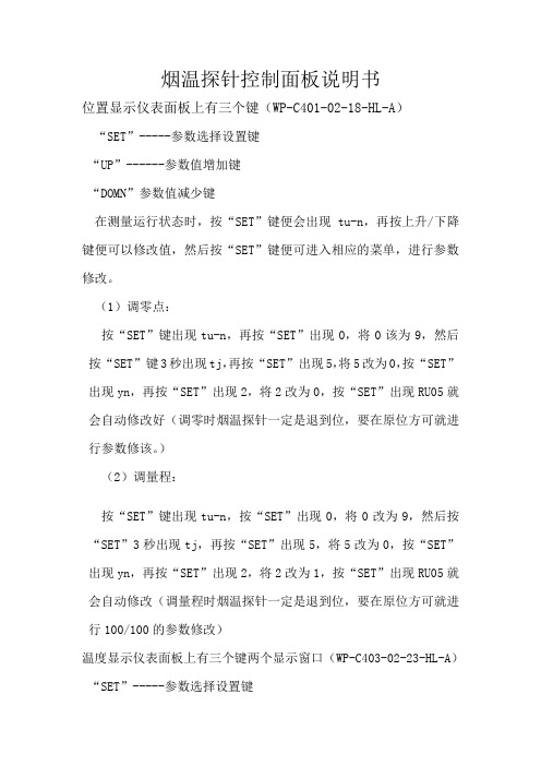
烟温探针控制面板说明书位置显示仪表面板上有三个键(WP-C401-02-18-HL-A)“SET”-----参数选择设置键“UP”------参数值增加键“DOMN”参数值减少键在测量运行状态时,按“SET”键便会出现tu-n,再按上升/下降键便可以修改值,然后按“SET”键便可进入相应的菜单,进行参数修改。
(1)调零点:按“SET”键出现tu-n,再按“SET”出现0,将0该为9,然后按“SET”键3秒出现tj,再按“SET”出现5,将5改为0,按“SET”出现yn,再按“SET”出现2,将2改为0,按“SET”出现RU05就会自动修改好(调零时烟温探针一定是退到位,要在原位方可就进行参数修该。
)(2)调量程:按“SET”键出现tu-n,按“SET”出现0,将0改为9,然后按“SET”3秒出现tj,再按“SET”出现5,将5改为0,按“SET”出现yn,再按“SET”出现2,将2改为1,按“SET”出现RU05就会自动修改(调量程时烟温探针一定是退到位,要在原位方可就进行100/100的参数修改)温度显示仪表面板上有三个键两个显示窗口(WP-C403-02-23-HL-A)“SET”-----参数选择设置键“UP”------参数值增加键“DOMN”参数值减少键上显示窗口为主显示窗口,测量时显示测量值PV,参数设定时显示参数代码。
下显示窗口为副显示窗口,测量时显示第一报警值,参数设定时显示参数值。
在正常测量运行状态时,按“SET”键便会出现tu-n,再按上升/下降键便可修改其值,然后再按“SET”键便可进入相应菜单,进行参数的修改。
(1)设置热电偶类型:有3为热电阻,4、5、6、7、8、9、10、11为热电偶。
按“SET”键主显示窗口显示tu-n,副显示窗口显示0,把改为19,按“SET”3秒,进入参数修改,主窗口显示CH-1,副显示窗口显示3或是其他值(热电偶类型),把3或是其他值(热电偶类型)改为6.按“SET”键主显示窗口显示U1-1,副显示窗口显示1000.再按“SET”键主显示U1-2,副显示窗口显示0,再按“SET”键返回主菜单。
SONAR-SOCTA点型复合式感烟感温一氧化碳火灾探测器使用说明书(使用产品前,请阅读使用说明书)1概述SONAR-SOCTA型点型复合式感烟感温一氧化碳火灾探测器(以下简称复合探测器)是法国范思科股份有限公司(FINSECUR)开发的复合探测器。
该产品具有多级烟雾灵敏度,多种感温类别及一氧化碳报警阈值可调功能,用户可根据自身使用需求任意设置。
具有一路有源输出节点,可驱动报警门灯(JBF1374型火灾光警报器)或小型继电器。
MCU采用消防专用芯片,具有性能稳定,可靠性高的特点。
1.1产品特点●污染自动补偿。
根据自身的污染程度进行零位修正,最大程度减少误报;●适用范围广,对不同材质燃烧后产生的白烟或黑烟均可响应;●感温支持多种类型报警:A1R,A2R,A1S,A2S;●感烟支持高、中、低三级灵敏度调节;●一氧化碳报警阈值可调:调节范围23~200uL/L(ppm);●可配置感烟、感温、一氧化碳单独报警或复合报警功能;●稳定性高,抗静电、抗灰尘附着、抗电磁干扰、抗腐蚀;●抗潮湿能力、抗环境温度影响能力强,可适应不同气候环境的要求;●采用SMT表面贴装工艺,采用导光柱;●内置短路隔离器(电源负极),隔离回路中存在短路故障的线路。
1.2适用范围●复合探测器应用于两总线火灾报警系统中,可配接青鸟消防报警控制器使用;●应用设计遵照国家标准GB50116-2013《火灾自动报警系统设计规范》;●主要用来探测可见的燃烧产物及起火速度缓慢的初期火灾,适用于宾馆客房、办公楼、图书馆、影剧院邮政大楼以及锂离子储能电站等场所。
1.3型号组成2工作原理复合探测器感烟探测部分由迷宫,红外发射部分、红外接收部分及相应的放大处理等电路组成。
正常工作时,当迷宫中没有烟时,红外发射管发出的红外光不能到达接收管,因此,放大器没有输出;而当迷宫中有烟时,红外发光管发出的光由于烟的散色作用,有部分红外光到达接收管,迷宫中烟的浓度越大,放大器输出就越大,当烟浓度达到设定报警阈值时电路给出报警信号。
一、设计依据:
1、西夏热电2*670t/h机组锅炉本体烟温探针采购合同;
2、锅炉炉膛宽度12400mm;
3、动力电源:380V、三相 50HZ;控制电源:220V单相;
二、供货品种、数量、规格要求:
1.炉膛出口烟气测温探针:
数量: 2台
型号、规格:供方的TS-O型、行程~6000mm。
要求:1)可不定期连续或间隙前进,也可停留在任意位置,超温时自动退回,报警烟温为540℃,退回温度为580℃;
2)具有就地操作、显示功能;
3)留有烟气温度信号及探针位置的接口(测温热电偶:K分度,位置
信号:4~20mA);
4)留有DCS的外接口,在DCS上完成烟温探针的进退控制和温度监视
警报;
5)电源要求:采用两路380V/220VAC三相四线制供电,每路最大容量
为2kVA,分别送至炉膛出口两侧烟温探针;
6)探针为铠装双支热电偶(型号WRNK-372)、温度信号二付(厂内标定
后出厂)、一作为退回动作和报警用,另一与温度显示仪表连接;
7)烟温探针供探管位置讯号,并供温度和位置显示仪表;
8)随机供电气箱一件,用以控制测温探针动作和集中温度、位置信号
接线;
9)烟温探针由单只电机驱动、电机型号M2QA80M4A型,N=0.55KW,
其绝缘等级为F级,防护等级为IP55;
10)烟温探针可在中心控制室进行伸出、退回、停止三种状态操作;
11)探针套管采用φ159×12。
注:相关的图纸资料将在5月中旬提供。
Highly Advanced, Full Featured 2-Color Pyrometer Series Metis M311 / M322FEATURES■Highest accuracy and repeatability even at high ambienttemperatures up to 80°C (176°F) without cooling■Temperature ranges between 300°C and 3300°C (572°F and 5972°F)■Fully digital and very fast with response time <1 ms■Adjustable or motorized focus optics■Small spot sizes from 0.8 mm■Laser, color video or thru-lens sighting■Dirty window programmable alarm■10-digit matrix display for temperature and IR sensor parameters■Push button device configuration or via software■ 2 high resolution 16 bit analog 0/4 to 20mA outputs■ 3 versatile configurable inputs or outputs■Analog input for external emissivity setting■Serial interfaces RS-232 and RS-485 (switchable)■Optional fieldbus connection: Profinet or Profibus APPLICATIONS■Induction heating■Steel/metals■Metal pour streams■Kilns■Vacuum furnaces■Welding■Ceramics■Composites■Sintering■Nuclear■Research anddevelopment.The Advantages and benefits for using a self-contained 2-color pyrometer:■Automatic compensation for viewing through dirty windows, dust and partial smoke■Compensates for changes in target emissivity■Measures smaller target than sensor’s field of view (FOV)■Unaffected by moving targets within FOVwww.processsensors Technical DataReference NumbersMetis M311 / Metis M322 Specify each with temperature range, sighting method and opticsNote: SensorTools software is included as standard equipment. Connection cables must be ordered separately. - 2 -In principle the M3 series only requires connection to a power supply to start a measurement.Metis M3 pyrometers are stand alone, self contained IR thermometers with direct outputs for easy integration in nearly all applica-tion environments.The short-wave spectral ranges of the various models are specially designed for accurate temperature measurements of metals and other bright, reflective materials.In comparison to radiation pyrometers, 2-color pyrometers measure in two spectral ranges simultaneously (at two wavelengths) and determine the temperature by forming the radiation ratio (quotient).In this method it is not necessary to know the emissivity of the target material or fulfill the sensor’s spot size with the target.Sighting Method SelectionPower Up and Measure TemperatureFeatures- 3 -Targeting light on / offSighting is used to pinpoint the location of the measured target.■Devices with integrated optics: Through lens view finder, laser targeting light or color camera module■Devices with fiber optics: Laser targeting lightThe view finder provides uprightimagery so that the target undermeasurement can be viewedvisually. A circular reticle shows themeasuring spot. Recommendedfor glowing measurement objects,as a red laser is difficult to detect.For deviceswith measuringrange above1800°C, theeyepiece canbe darkened foreye protection.Laser targeting uses a redlaser dot showing the centerof the measuring field. At thefocus point, the laser dot isthe smallest and provides thesharpest image, so that themeasuring distance for thesmallest spot size canbe easily determined.Pyrometers with acolor camera moduleprovide a composite videooutput that can be connectedto a video monitor or PC witha converter. The pyrome-ter is aligned via a circularreticle on the TV screen andis recommended for remoteobservation of glowing hottargets or viewing down sighttubes. The camera providesautomatic, highly dynamicadjustment of the picturebrightness.Focus- 4 -Comprehensive Settings■Each digital output switches a low voltage output active or inactive (NC or NO, adjustable) with several selectable states (rear panel LEDs indicate the switching state): • Limit switch for decreasing or exceeding a certain tem-perature threshold• Material detection (exceeding the beginning of tempera-ture range)• Device state (device is ready for operation)J Measuring Mode2-color mode, switchable to 1-color modes (channel 1 or 2 se-lectable) for use as a standard radiation pyrometer.J Dirty Window AlarmA signal strength monitoring function detects the degree of con-tamination of the pyrometer‘s optics, viewing window or identify interferences (dust...) in the IR sensor’s sight path and triggers an alarm if activated.J Switch-off LevelThe switch-off level defines a signal level, the temperature mea -surement is switched off, due to low level signal strength (e.g. if the contamination in the pyrometer field of view is too strong).J Peak Picker / Maximum Value StorageThe peak picker also detects the temperature when the mea-surement object appears only briefly in the pyrometer’s field of view. Application example: rolling mills with scaled surfaces.J Material PropertiesThe input options for material entry have been simplified: ■Emissivity slope: Measuring objects whose emissivity is different at the two wavelengths (e.g. bright, unoxidized metal surfaces), the emissivity ratio can be adjusted. Targets with the same emissivity at the two wavelengths can be measured without adjustment of the slope/ratio setting.■Emissivity: Each material has a max. emissivity of 1.00 which can be set, an adjustment up to 1.20 can be used. The emissivity adjustment above 1.00 allows for temperature corrections due to higher background reflection.■Transmittance: For measurements through windows signal losses occur by transmission of the window. This value can be adjusted based on the window material.Values in the optics tables illustrate the focused measuring distances and respective spot sizes. The spot size diameter for distances not given in the table can be interpolated. The pyrometer can be used at distances other than its’ focal dis -tance, however the spot size is generally larger and therefore the target size must be larger. Focusable optics (manual or motorized focus) can be continuouslyadjusted within the minimum and maximum specified measurement distance, providing the smallest possible spot size diameter at that focus distance.or longer distance than the focus distance) to determine the average temperature of a bigger spot.Standard: OQ25Miniature: OQ12Brazing Pipe BendingSemiconductor - 5 -1.2.3.1.Typical ApplicationsSpot size ØM e a s u r i n g d i s t a n c e (st e pl e s s ad j u s t a b le )F o c u s a b l e o p t i c sAperture Ø2. Pull / push in3. Lock turn clockwiseManual Focus - Via push buttons - Via PC softwareMotorized focus14 mm FSC = Full scale temp. rangeModel Selection Table - M311 / M322Example: M311-0600-1400-1-5-2-13-0-4-2-3-AThis model refers to: Model M311, temperature range of 600-1400°C, laser targeting, RS232 & RS485 communication, manual focus optics, 1 ms response time, std. version sensor, onboard temperature display,two 0/4-20 mA outputs, 3 digital inputs/outputs, optics type A.- 6 -■Record interval setting for acceptable data size.■ ■ ■ ■Create a service file with settings for remote diagnosticsOQ12: Optics 12 mm Optics 25 mm: OQ25Manual focusable opticsMotorized focus opticsFiber optic devices, focusable opticsPROCESS SENSORS CORPORATIONIR Temp. Sales Office: 787 Susquehanna Avenue, Franklin Lakes, NJ USA • Tel: 201-485-8773 • Fax: 201-485-8770Corporate Headquarters: 113 Cedar Street, Milford, MA USA • Tel: 508-473-9901 • Fax: •*************************Process Sensors reserves the right to make changes in scope of technical progress or further developments.Metis_M311_M322 (Feb. 05, 2018)Recommended AccessoriesDimensionsHA20 Ball and socket swivel mount for sensor alignmentHA22 Ball and socket swivel mount for water cooling housing HA10 Mounting bracket for sensor alignmentHA12 Mounting bracket for water cooling housingHA14 / 15 Adjustable mounting bracket for fiber optics OQ12 / OQ25KG10 Aluminum water cooling housingKG20 Aluminum cooling plateBL10 / 11 Air purge for devices with motor focus / manually focusable opticsBL13 / 14 Air purge for fiber optics OQ12 / OQ25AL11 / 43 Connection cable, 14-wire (available in 5 m steps) with right angle connector / straight connectorAU11 / 43 Connection cable, 14-wire, interface converter RS-232⇔USB with right angle connector / straight connector AV11 / 43 Connection cable, 14-wire, interface converter RS-485⇔USB with right angle connector / straight connector AK50 Connection cable for camera module (Limosa-plug ⇔Cinch-plug, available in 5 m steps)AK54Profinet netwok cable, Ethernet CAT6 (available in 5 m steps)AK72 / 73 / 76 / 81 Profibus connection cable (input cable / output cable / devices connection cable / terminating resistor) IF00 LED digital indicator for remote adjustment of IR sensor parameters950-004Power supply 24 V DCHA10HA12KG10IF00。
编号编号 SC SC104010401040 TS TS--OSM OSM 版本版本 REV REV 00 日期日期 2020101010..1010 编写编写 校对校对 批准批准新疆和丰新疆和丰电厂电厂2x300MW 机组锅炉机组锅炉TS TS--O 型非冷式温度探针型非冷式温度探针 安装安装、、运行与维修手册上海克莱德贝尔格曼机械有限公司上海克莱德贝尔格曼机械有限公司20201010年10月言前 言本运行手册向我们的用户提供最详尽的资料,这些资料来自于我们的实践经验。
用户必须遵守运行手册,这样在布置和运行温度探针时可避免出现问题或发生危险。
技术数据如有更改,恕不通知。
在规划、使用、运行及维修温度探针时,用户不仅需要遵守运行手册,而且必须遵守相应的法规与标准,以防止事故发生。
我们推荐由上海克莱德贝尔格曼机械有限公司的专业人员来实施维修和维护。
如有任何问题,请致电我们的服务部门。
电话:0086 -021-********-301传真:0086 -021-********目 录录第一章第一章 说明及设计参数说明及设计参数第1-1节 温度探针说明第1-2节设计参数表第二章第二章 安装及调试安装及调试 第2-1节 温度探针安装 第2-2节调试第三章第三章 温度探针运行温度探针运行第3-1节 运行第3-2节温度探针故障第四章第四章 维护及检修维护及检修 第4-1节 温度探针维护 第4-2节温度探针检修第一章第一章 说明及设计参数说明及设计参数第1-1节 温度探针说明1.原理和设计参考图1温度探针一般用在锅炉过热器或再热器进口的关键区域,以防止锅炉启动过程中管壁金属的过热。
温度探针由一内含探测元件的枪管构成。
枪管借助行走箱伸入或退出炉膛以测量沿锅炉宽度的炉膛烟气温度。
为了测量炉膛内各点的烟气温度,控制系统的设计能够使温度探针停留在其行程上的每一个预定位置。
并通过位置指示仪显示出热电偶末端在炉膛内的位置。
2.大梁大梁基本上由H 型钢构成,用作行走箱行走的轨道。
与行走箱上的驱动小齿轮啮合的齿条布置在H 型钢下方。
前部托轮组位于大梁的前端以支承和引导枪管。
炉墙接口箱位于大梁前端板上将温度探针固定在锅炉炉墙上。
另一个支撑点位于大梁后部。
3.行走箱行走箱由箱体、电机齿轮箱组成,行走滚轮固定在箱体上。
齿轮箱输出轴驱动行走箱上的小齿轮与大梁上的齿条啮合,实现行走箱的轴向移动。
4.测量装置及枪管枪管由不锈耐热钢制成,其末端固定在行走箱上,前端固定在前部托轮组上。
枪管头部同样用不锈耐热钢制成保护套,其上开孔以使烟气在热电偶端部四周流动。
因此,热电偶端部可免受损坏。
热电偶元件从枪管中心穿过,并与后端接线座相连。
接线座配导线插头,补偿导线将信号传送到安装在导轨上的固定接线盒(对照点)。
仪表导线引至该固定接线盒。
5.炉墙接口箱(负压)带刮灰板的墙箱为穿过炉墙的枪管提供密封。
刮灰板本身可调,以适应由于枪管自身挠度或炉墙热膨胀造成的枪管中心位置的变动。
6.支吊通过前端板与炉墙接口箱,温度探针前端被固定在炉墙上;后部支吊装置则安装在由用户提供的支架上。
支吊装置的设计应能适应锅炉的水平和垂直方向的膨胀。
用户在安装探针时,应考虑到这些膨胀。
7.电气部分总体说明温度探针电气部分主要由控制柜、就地控制箱以及热电偶、电位器、行程开关等组成。
控制柜、就地控制箱内的接线已在工厂内连接完毕,并通过联机调试。
(1)控制柜控制柜是温度探针的控制中枢,安装于电气设备间。
空气开关、变压器、接触器、继电器、热继电器和保险丝等安装在控制箱内,其前部有检查门、底部有电缆入口。
(2)就地控制箱就地控制箱安装在温度探针的大梁上,用作温度探针的就地控制。
下列元件安装在就地控制箱的箱门上:电源指示灯运行指示灯故障指示灯就地/遥控选择开关前进按钮后退按钮停止按钮停机 /复位按钮(3)热电偶热电偶与补偿导线相连,热电势通过补偿导线传送至温度变送器的热电偶输入端, 并用温度指示仪指示炉膛内的烟气温度。
(4)电位器由同步齿型带驱动的10圈线绕式电位器通过电缆与电阻/电压变送器相连,用位置指示仪(刻度0~100%)指示热电偶探头的实时位置。
(5)限位开关温度探针提供下列两个限位开关:a)停止行程开关SLS若按下“前进”或“后退”按钮,SLS的动作使得温度探针的运动由向后变为向前。
若按下“停机/复位”按钮,则SLS的动作将使温度探针停在停用位置。
b)后退行程开关RLSRLS的动作使温度探针的运动由向前变为向后。
8.示意图TS-O非冷式温度探针 图1第1-2节设计参数表设计参数表设计参数1.常规参数机组 300MW 温度探针数量 台 2 测温范围 0-540°C 2.驱动功率kW 0.55 行程 m5.5 行走速度 m/min 1.44 3.几何尺寸及材料3.1.热电偶型号WRNK-372铠装热电偶 外径mm 6 材料 镍铬-康铜3.2.枪管外径mm 88.9 壁厚mm 4 材料 T914.炉墙接口箱 负压电机参数电机参数电机齿轮箱型号TSOGB 电机型号M2QA80M4A-J4 功率kW 0.55 转速r/min 1400 频率H z 50 电压V 380 功率因素CosΦ 0.75 额定电流A1.52 启动电流IA/IN A5.2 绝缘等级F 电机防护类型 IP 55 冷却方式风扇冷却转子设计 鼠笼式轴承类型 球轴承第二章第二章 安装及调试安装及调试安装及调试 第2-1节 温度探针安装 1.运输及存放必须非常谨慎的运输探针及附件以防止损坏。
大梁上的吊耳可用于运输。
(见图4) 在必须长期存放的情况下,探针应该存放在有暖气的室内,以防止电气驱动和控制设备因潮湿和闲置而腐蚀。
如有疑问或在极端气候条件下,务必通知上海克莱德贝尔格曼公司。
注意:应保护所有光制元件(如垫圈、联结元件等)以免受腐蚀(如螺母涂油脂)。
2.炉墙接口箱炉墙接口箱应装在炉壁的波形箱上,保持铰接螺栓的通孔绝对水平是非常重要的,可避免温度探针倾斜。
接口箱定位后,应牢固地焊在波形箱上。
3.前支承(1)用吊车将探针提起到安装高度并暂时保持此高度; (2)从探针前端板上取下铰接螺栓;(3)将探头置于墙箱内,前支承插入炉墙接口箱;(4)插入铰接螺栓后,探针前端可吊挂在炉墙上,并可在垂直面上绕铰链自由旋转。
4.后支吊(1)探针后部支吊必须安装在支架,或其它能够使探针的安装位置在轴向、水平方向和垂直方向精确定位的位置上;(2)使用起重机吊起探针,以使螺杆可插入支架的支吊孔并紧固;(3)螺杆必须能在探针轴线方向上移动,以使探针定位在与炉墙成预定角度; (4)利用螺杆调整探针的最终高度; (5)在校正位置后,用螺母锁定螺杆。
5.电气安装探针内部的接线已在出厂前完成。
在安装现场布置电源及控制电缆,并连接到接线 盒。
按接线端子图布置电缆,在接线端子图中包含电缆截面尺寸。
6.装配检查探针装配完毕后,检查以下细节是否与安装文件一致:(1)检查安装位置;(2)鉴于探针固定在位于锅炉上的前支承处,探针随着炉墙移动;(3)锅炉(安装位置)冷态条件下,探管位置应当适当倾斜以考虑炉墙垂直方向的热膨胀,锅炉在热态条件下,探管应水平安装;(4)探头的停用位置必须符合规定。
同样,在探针完全伸出时,探头到锅炉内墙的距离必须与设计尺寸一致。
如有偏差,应与上海克莱德贝尔格曼公司联系;(5)在所有运行工况下,探管都应当能够灵活的在刮灰板中作轴向和径向移动;(6)检查可能用到的密封空气是否正确连接。
第2-2节 调试1.启动前工序(1)调试前应除去探针上的灰污,卸下全部固定部件(如运输中使用的固定装置和角钢支架等);(2)仔细检查运输或安装过程中探针有无损坏,更换遗失或损坏的部件。
重点检查电气部件;行走箱;(3)齿轮箱在出厂前已加注润滑剂,日后的润滑按润滑表进行。
注意:保护所有光制元件(如螺栓,联结元件等)不受腐蚀(如涂油脂);(4)检查枪管在大梁箱体的中心位置,确保刮灰板可灵活移动;(5)检查探针停止位置、后退位置;(6)检查探针是否按接线端子图接线。
2.调试探针初次调试应按以下步骤进行:(1)切断驱动电机电源。
用手摇曲柄将探针行走箱前移0.3米;(2)检查电机转向和探针行走箱的移动方向:合上电源,按动“前进”按钮,行走箱向前移动时,表示电机转向正确,否则交换电机接线盒内的两根电机接线;(3)检查前端限位开关:在探针前进状态时,手压限位开关,行走箱立即向后移动。
如不返回,立即关闭电源,检查控制系统;(4)检查后端限位开关:在探针向后移动时,拨动后端限位开关,探针应立即向前移动。
否则,关闭电源,检查控制系统;(5)各项检查完成后,探针应进行整体自控试运。
进一步的详细内容见电气控制。
第三章第三章 温度探针运行温度探针运行温度探针运行第3-1节 运行1. 就地运行(1)合上电源,就地控制箱上“电源”指示灯亮。
(2)设定选择开关为就地控制。
(3)按“前进”按钮,电动机起动,枪管向前运动,“运行”指示灯亮。
当测得的温度低于设定的报警温度(540°C ),则枪管一直向前运动直至:1) 后退行程开关RLS 动作。
将使枪管自动逆向运行。
2) 操作人员按下“后退”按钮。
这将使枪管在其行程的任意位置立即逆向运行。
3) 操作人员按下“停止”按钮。
使枪管在其行程的任意位置立即停止运动,以便温度探针连续监测该点的温度。
4) 操作人员按下“停机/复位”按钮。
这将使枪管在其行程的任意位置立即逆行,直至回到停运位置停止运行。
(4)在就地运行时,在集控室内的仪表显示测得的烟气温度和枪管端部的位置。
(5)当枪管向前运行或停止时,按下“后退”按钮会使枪管逆行直到:1) 停止行程开关SLS 动作。
这会使枪管运行自动变为向前。
2) 操作人员按下“前进”按钮。
这将使枪管在其行程的任意位置立即由向后改为向前运行。
3) 操作人员按下“停止”按钮。
这将使枪管在其行程的任意位置立即停止运动,以便温度探针连续监测该点的温度。
(6)当枪管前行或逆行时,或当枪管停止时,按下“停机/复位”按钮将使枪管退回至停运位置。
(7)当温度探针监测到炉膛烟气温度达到或超过设定的报警温度(540°C )时,并发出“烟气温度高”报警信号。
当温度探针监测到炉膛烟气温度达到或超过设定的高高报警温度(600°C )时,枪管将强制退回至停运位置。
2. 远程运行(1)合上电源,就地控制箱上“电源”指示灯亮。
(2)在就地控制箱上将选择开关设定为遥控操作。
(3)按“前进”按钮,电动机起动,枪管向前运动,“运行”指示灯亮。
当测得的温度低于设定的报警温度则枪管一直向前运动直至:1)后退行程开关RLS动作。
将使枪管自动逆向运行。
1)后退行程开关RLS动作。