DUPLOMATIC伺服刀塔电气说明书(英文)
- 格式:pdf
- 大小:933.56 KB
- 文档页数:22
內部位置上層-分度模式-使用說明u操作上的注意事項:使用內部位置上層-分度模式時,在驅動器送入電源之後,請先執行回原點動作後,再開始跑分度位置,以確保位置的正確性。
參數 Pr46第一命令分周比分子、Pr49分度分割數設定、Pr4B命令分周比分母,設定完成後,為確保分度位置的正確性,請先執行回原點動作後,再開始跑分度位置。
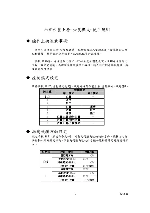
u控制模式設定請將參數 Pr02[控制模式設定],設定為內部位置上層-分度模式,設定值8。
控制模式設定值第1模式第2模式【0】位置-1 速度-2 扭力-3 位置速度4 位置扭力5 速度扭力6 位置上層-絕對位置-7 位置上層-相對位置-8 位置上層-分度模式-u馬達旋轉方向設定設定參數 Pr41[脈波命令反轉],可指定伺服馬達的旋轉方向。
旋轉方向為面對軸心所觀察的方向。
下表為伺服馬達執行各種功能動作時的對應旋轉方向。
設定值功能/ 動作旋轉方向回原點方向CW手動遞增MR-Inc CCW【0】手動遞減MR-Dec CW分度索引位置CCW排列回原點方向CCW手動遞增MR-Inc CW1手動遞減MR-Dec CCW分度索引位置CW排列u I/F接線圖相輸出相輸出相輸出u I/F接腳信號與位準定義Pin No. 腳位定義1 功能1 腳位定義2 功能2 位準1 PosBit6+ 分度點選擇6(+) A接點2 PosBit5+ 分度點選擇5(+) A接點34 PosBit6- 分度點選擇6(-) A接點56 PosBit5- 分度點選擇5(-) A接點7 COM+ 信號電源(+)8 Origin 原點Sensor 輸入B接點9 E-STOP 緊急停止輸入A接點10 BK-OFF- 解除煞車(-) DO1- 狀態編碼1(-) 輸出11 BK-OFF+ 解除煞車(+) DO1+ 狀態編碼1(+) 輸出12 ZSP 零速度檢知DO2 狀態編碼2 輸出13 GND 類比信號地1415 GND 類比信號地1617 GND 類比信號地1819 CZ Z相信號開集極輸出20 PosBit4 分度點選擇4 輸入A接點21 OA+ A相信號(+) 輸出22 OA- A相信號(-) 輸出23 OZ+ Z相信號(+) 輸出24 OZ- Z相信號(-) 輸出25 GND 類比信號地26 MR-Step 手動移動-單步MR-Dec 手動單步-遞減輸入B接點/ A接點27 MR-Con 手動移動-連續MR-Inc 手動單步-遞增輸入B接點/ A接點28 PosBit3 分度點選擇3 輸入A接點29 SVO-ON 馬達通電激磁輸入A接點30 PosBit2 分度點選擇2 輸入A接點31 FuncBit1 分度功能1 輸入A接點32 FuncBit2 分度功能2 輸入A接點33 PosBit1 分度點選擇1 輸入A接點34 SVO-RDY- 伺服系統待命(-) DO3- 狀態編碼3(-) 輸出35 SVO-RDY+ 伺服系統待命(+) DO3+ 狀態編碼3(+) 輸出36 SVO-ALM- 伺服異常警報(-) DO4- 狀態編碼4(-) 輸出37 SVO-ALM+ 伺服異常警報(+) DO4+ 狀態編碼4(+) 輸出38 ON-POS- 位置完成(-) DO5- 狀態編碼5(-) 輸出39 ON-POS+ 位置完成(+) DO5+ 狀態編碼5(+) 輸出40 TLC 扭力極限檢知DO6 狀態編碼6 輸出41 COM- 信號電源(-)42 IM 扭力監視輸出43 SPM 速度監視輸出4445464748 OB+ B相信號(+) 輸出49 OB- B相信號(-) 輸出50 FG 大地接地u分度控制輸入設定1.自動索引模式執行回原點、分度點移動前,控制接腳請先輸入扭力限制動作後,再輸入回原點或分度點移動。
迪普马刀塔中文说明书迪普马刀塔中文说明书的制作:刀塔:包括刀塔本体、刀塔连接件、刀塔使用说明。
1、刀塔本体由两部分组成,底座与刀塔本体的连接方式有4种,分别为卡扣式、固定式、卡扣式、滑轨式。
底座的卡扣式固定在刀塔的支架上,可将底座固定在刀塔底座中,使刀塔整体保持水平。
卡扣式固定方式比较简单,可以直接将底座固定在刀塔桌面上,但占用刀塔桌面空间较大,不适用于小型刀塔。
固定式一般用于大型刀塔,可将底座固定在刀塔底座上,但占地面积较大,不适合小型刀塔使用。
滑轨式目前较为普遍,适合小型刀塔使用,它可以通过滑轨将刀塔支架固定在刀塔本体上,其结构简单,占地面积相比固定方式也比较小。
2、刀塔连接件由两部分组成(可以按照实际尺寸选择),在刀塔本体的上方可安装刀塔连接件,连接到底座上的一个转盘中以提高刀塔之间的稳定性。
连接件的两侧有两个滚轮,转动滚轮的时候,刀塔连接件通过橡胶圈摩擦产生震动让转盘转动。
当轮子转动到一定角度后转盘会自动停止转动,因此在刀塔内没有东西可以直接旋转转盘。
同时由于转盘转轴在底座上,因此转盘的转动会产生强大的惯性,同时转动也会带动轮子,从而使刀塔稳定使用。
3、刀塔使用说明(见后),由一层塑料板组成;在刀塔的内壁上设有一层软胶,当有一根长丝线穿过时便可从该丝上将塑料丝割断。
在刀塔底部有一层保护布(见后)。
如果需要将刀塔置于高处,需要在刀塔顶部垫一块砖块进行支撑。
4、塑料板的宽度和厚度根据现场的实际情况来决定;产品说明:包括产品的名称与型号、主要材料、加工方法与尺寸、使用说明、安全警示、运输和安装注意事项、维护方法、材料和尺寸、使用年限和注意事项、运输过程中注意事项、储存、维修方法及注意事项。
马刀特点:整体为铝材料,重量轻,耐老化等特点。
其特点:外形美观大方、造型流畅、刀体结构简单、制造成本低、操作方便、可重复使用。
5、如果刀塔有不同颜色可以根据使用说明书进行制作。
刀塔的刀口是用胶水粘合的,所以需要注意刀口部分的光滑。


BSV-N series 25ELECTROMECHANICAL TURRETSThe data given in the I.T. are subject to technical modifications without notice.TECHNICAL INFORMATIONI.T. 6430ISSUED09-08GBDFEBAPMNClamping on 3-part Hirth front toothing – High stifness and accuracy – No lifting during rotation.Water-proof housing with oil immersed mechanism, life lubricated.Single three-phase electric motor for rotation and clamping.WORKING PRINCIPLEA) Electrical motor (three-phase)B) GearboxC) Rotation and cam locking mechanism D) Pre-indexing solenoidE) Pre-indexing control switch F) Shock-absorber system G) Preloaded locking springH) 3-parts front coupling I ) Locking control switchL) Angular position transmitter (absolute)M) Rotating plate N) Coolant flangeP) Quick change coolant valve(1) Other versions on request.(2) Filtering ≤ 150 µm.Technical dataSizeBSV-N120/25BSV-N160/25BSV-N200/25BSV-N250/25BSV-N320/24BSV-N400/20Tool stations N°8÷128÷128÷128÷128÷128÷12Version(1)stdslowvery slowfaststdslowstdslowvery slowstdslowstdslowstdslowvery slowInertia of transportable mass Kgm 20,450,81,20,550,91,834,58591522223270Indexing time(including locking)30°s 0,410,480,580,410,480,580,650,7810,7811,101,251,251,452,0545°s 0,480,570,690,480,570,690,780,941,180,941,181,251,451,451,652,50180°s 1,161,381,651,161,381,651,832,232,802,232,802,713,183,183,665,53Rotating time only30°s 0,150,180,210,150,180,210,240,300,360,300,360,330,380,380,450,6845°s 0,230,270,320,230,270,320,360,450,540,450,540,490,580,580,671Indexing frequency a =90°cycle/min16141114121011979765543Electric supply See wiring diagramMass (without disc)~ Kg405292120240420Ambient temperature range °C5 ÷ 405 ÷ 405 ÷ 405 ÷ 405 ÷ 405 ÷ 40Coolant supply:(2)• Costant flowbar 777777• Pressure cut-off during turret rotation bar141414141414Protection degree (DIN 40050)IP65IP65IP65IP65IP65IP65Indexing accuracy∆β = ± 4"( 1,9 µm/100 mm)Repeatibility accuracy ∆a = ± 1,6" ( 0,78 µm/100 mm)AccuracyLoading capacityβThe diagram refers to F 1 values which cause elastic yelding within the rates shown in the schedule.T urret size120160200250320400Max. elastic yeldingmm 0,050,070,080,140,120,16Distance from centre of measuring pointmm140170220270330350[mm]200000100000800006000040000200001000080006000400020001000100200300400500[mm]200000100000800006000040000200001000080006000400020001000100200300400500[mm]200000100000800006000040000200001000080006000400020001000100200300400500[mm]200000100000800006000040000200001000080006000400020001000100200300400500S : CHIP CROSS-SECTION (max) for steel R = 600 N/mm 2 Ks = 2.200 N/mm 2N : POWER (max) for V t = 200 m/min• For any material with different Ks: Sx = S X 2.200KxPARAMETERS FOR TURRET SELECTION[mm]1008060402010864210,801002003004005000,60,530010050403020105150N[kW]• For different cutting speeds: Nx = N XVtx2001) Inlet coolant position, at choise.2) Right or left coolant outlet position.3) Adjustable coolant ring.4) Coolant outlet displacement range.5) Soft surface for boring the disc reference pins.6) Reference pin to be positioned on both side, at choise.7) Reference pins between tool disc and turret.8) Electrical connections on both side, at choise.Important: The connection cable must be provided with fittings and gaskets in order to avoid penetration of water into the turret.(4)3)2)TOOL DISC INTERFACE1) Inlet coolant position, at choise.2) Right or left coolant outlet position.3) Adjustable coolant ring.4) Coolant outlet displacement range.5) Soft surface for boring the disc reference pins.6) Reference pin to be positioned on both side, at choise.7) Reference pins between tool disc and turret.8) Electrical connections on both side, at choise.Important: The connection cable must be provided with fittings and gaskets in order to avoid penetration of water into the turret.(4)3)2) )TOOL DISC INTERFACE1) Inlet coolant position, at choise.2) Right or left coolant outlet position.3) Adjustable coolant ring.4) Coolant outlet displacement range.5) Soft surface for boring the disc reference pins.6) Reference pin to be positioned on both side, at choise.7) Reference pins between tool disc and turret.8) Electrical connections on both side, at choise.Important: The connection cable must be provided with fittings and gaskets in order to avoid penetration of water into the turret.(4)(3)(2) )TOOL DISC INTERFACE1) Inlet coolant position, at choise.2) Right or left coolant outlet position.3) Adjustable coolant ring.4) Coolant outlet displacement range.5) Soft surface for boring the disc reference pins. 6) Reference pin to be positioned on both side, at choise. 7) Reference pins between tool disc and turret. 8) Electrical connections on both side, at choise. Important : The connection cable must be provided with fittings and gaskets in order to avoid penetration of water into the turret.(4)3)2)TOOL DISC INTERFACE1) Inlet coolant position, at choise.2) Right or left coolant outlet position.3) Adjustable coolant ring.4) Coolant outlet displacement range.5) Soft surface for boring the disc reference pins.6) Reference pin to be positioned on both side, at choise. 7) Reference pins between tool disc and turret. 8) Electrical connections on both side, at choise. Important : The connection cable must be provided with fittings and gaskets in order to avoid penetration of water into the turret.(4)3)2)3/8" GAS (1)TOOL DISC INTERFACE1) Inlet coolant position, at choise.2) 4 coolant outlet position.3) Coolant valve. The valve can be fitted on one of the 4 coolantoutlet position. The drawing represents how the valve ispositioned when the disc is mounted. Without the disc, thevalve produtes by 2 ÷ 3 mm is comparison with the positionindicated.4) Coolant outlet displacement range. 5) Soft surface for boring the disc reference pins. 6) Reference pin to be positioned on both side, at choise. 7) Reference pins between tool disc and turret. 8) Electrical connections on both side, at choise. Important : The connection cable must be provided with fittings and gaskets in order to avoid penetration of water into the turret.(4)5)2)+ 0,1~ 3WIRING DIAGRAM(1) Other voltages on request.(2) The termal detector gives a signal only motor overheating.WIRING NUMBERREF .COMPONENT CHARACTERISTICS SIMBOLS COLOURSIGNALS 1ELECTRIC MOTOR (three-phase)(1)220-380 V 50/60 Hz For other characteristics see Tab. 1U1V1W1U2V2W2WHITE GREEN BLACK WHITE GREEN BLACK See Tab. 22THERMAL DETECTOR 135 °C 1,5A 250V 12BROWN BROWN (2)3BRAKE 24 V D.C.BSV-N 120/160 = 8 W BSV-N 200/400 = 12 W 34GREEN GREEN 4INDEXING SOLENOID 24V D.C.44 W 56BLUE BROWN 5INDEXING CONTROL SWITCH 24V D.C. ± 10%200 mA (load)OUTPUT -PNP-NO 789BROWN BLACK BLUE + V D.C.EXIT 0 V D.C.6LOCKING CONTROL SWITCH 7109BROWN BLACK BLUE + V D.C.EXIT 0 V D.C.7ANGULAR POSITION TRANSMITTER (ABSOLUTE)24V D.C. ± 10%350 mA (supply)50 mA/exit (load)OUTPUT -PNP79111213141516BROWN BLUE WHITE YELLOW GREEN VIOLET BLACK PINK+ V D.C.0 V D.C.Bit 1Bit 2Bit 3Bit 4Strobe Parity check GREEN / YELLOW PECYCLET a b . 1F U N C T I O N P O S I T I O N S 1234567891011121 B I T 1010101010102 B I T 0110011001103 B I T 0001111000014 B I T 000000011111P A R I T Y C H E C K 110100110010S T R O B E 111111111111C W ✦ C C W T a b . 2T U R R E T S I Z E 120160200250320400P R O G R A M M I N G T I M E T 1 (m s )50505050100100T 2 (m s )200200200200200200A L L O W E D L A G T I M E M A X R 1 (m s )S t a n d a r d a n d f a s t 404050507070S l o w e d 404060708080R 2 (m s )S t a n d a r d 404070809090S l o w a n d v e r y s l o w 40408090100101. – SignalsT o get a change of positions on the BSV-N turrets, the con-trol equipment (usually a N.C. equipment) must control thecomponents mentioned below according to a well definedsequence (see wiring diagram on page 15).• Motor (1)• Brake (3)• Indexing solenoid (4)The following output signals from the turret are provided fordriving the positioning cycle:– Angular position given by the angular position transmitter (7)– Indexing control switch (5)– Locking control switch (6).1. – Description of the operating sequenceThis description refers to sequence cycle: the first part gives thesequence to pass from position 1 to position 2 with clockwiserotation, the second part gives the sequence to pass fromposition 2 to position 12 with counterclockwise rotation.As indicated by the cycle, the controls are to be performedaccording with the following sequence:• De-energize the brake (3) and start motor rotation in thedesired direction.• If, as in the case shown by the diagram, the next position(pos. 2) is the Stop position, when the strobe signal reacheda zero level, the solenoid (4) is to be energized.In case of passage from position 2 to position 12, wait forthe reading signaling the passage on pos. 1 then, sincethe next one is the Stop position, wait until the next strobesignal reaches a zero level and (at that time only) energizethe solenoid (4).N.B.: T he maximum lag time between the reading of the strobesignal and the excitation of the solenoid (4) cannot exceedthe R1 values indicated in the table.• The turret goes on rotating until the indexing pin, pushedby the solenoid (4), enters into the mechanical stop slot.This movement is detected by the sensor (5) which mustimmediately stop the motor that, once expired the T1 timewill re-start rotating in the opposite direction.• During this phase the turret is locking and its locked positionis detected by the sensor (6) and this signal is used to stopthe motor (1). The maximum lag time between the signal ofthe sensor and the stopping of the motor must never exceedthe R2 value shown in the table. At this point the machine canbe started, in order to go on working.• The solenoid (4) is to be de-energized after the expirationof the T2 lag time starting from the moment when the sensor(6) signal is read.N.B.: The T1, T2, R1, R2 times must be understood as realtimes execution of the controls and the signals checked onthe terminal board of the turret.For an accurate detection and measurement of the abovementioned values it is advisable to use adeguate instru-mentation such as an oscilloscope with memory and currentsensing devices.(*) See tab. 2 sheet 16 (Cycle). CYCLE DESCRIPTIONSFlow chart"BSV-N *" turrets have been designed for modular fitting onto the different driven tool systems.BS *-DT• With ODT -N driven tool device.• Tool coupling according to DIN 1809.• Tool disc with axial seats.• Front machining.For further information please contact our T echnical Dept.BS *-TR• With IDT -R driven tool device.• Tool disc with radial seats.• Front machining.NOTE: Front and back machining for sub-splinde machines is alsoavailable on request.DRIVEN TOOLS SYSTEM"PA" VERSION TURRETS (with axial throught-bore)T urret sizeBSV-N 120BSV-N 160BSV-N 200BSV-N 250BSV-N 320BSV-N 400ø D202028282860A 370370413413530588For other information see the Technical Information UCN-*.UCN CONTROL UNITThe UCN control unit manages the moving cycle of BSV-N turret in a simple and optimized way: simple and optimized software; no memory positions are occupied in the machine control; automatic chose of the shortest path; steady monitored for faults.(1) From 20 to 29 the performance and the overall dimensions do not change.SERIE 20 ÷ 29(1)POSITIONSCODE Nr. 8 Pos.8Nr. 12 Pos.12SIZECODE 120120160160200200250250320320400400BSV-N * - * - * /2* - * - * - ( * )IDENTIFICATION CODEOPTIONALS AXIAL THROUGH BORECODE Without(Standard)—With (Optional)PA MOTOR VOLT . and FREQUENCY 220-380220-380 V - 50/60 Hz 230-400230-400 V - 50/60 Hz 400-440400-440 V - 50/60 HzCODE FREQUENCY and INERTIA 50 H 50 Hz Fast 60 H 60 Hz Fast 5050 Hz Standard 6060 Hz Standard 50 L 50 Hz Slow 60 L 60 Hz Slow 50 LL 50 Hz Very slow 60 LL 60 Hz Very slow。
TMC控制器 安裝說明書前言TMC控制器是用來控制DM刀塔的換刀定位功能, 與車床控制器間的連線功能強大. TMC控制器並有RS232連接埠,用來跟筆記型電腦或桌上型電腦連線MODEL:TMC-14-230-12-16-1.2/11 型號Code: 0497012251 料號S/N ********* 序號SET FOR: DM-16 S/N XXXXXXXX 配對刀塔的序號型號說明:MODEL: TMC -14 -230 -12 -16 -1.2 /11硬體版本 電壓 刀位數 刀塔規格 刀盤慣量 軟體版次2.3.絕對嚴禁打開TMC的外殼TMC歸類為國際產品標準EN-61800.TMC與刀塔一起通過測試且符合下列規範CEI EN 61800-2 and CEI EN 61800-3 and CEI EN 61800-5-1.TMC的應用等級是C3(使用在第二環境或不與民用環境連接之工業輸電網路)這類設備不得用於家用之低壓公共輸電網路因此,若將此設備使用於民用環境將可能會干擾其它電子設備,需設法避免此狀況發生在連接至TMC的三相電源前需加裝濾波器以符合EMC規範要求, 建議使用的EMC濾波器為‘FINMOTOR FIN 1200-010V’或更高等級.TMC控制器需透過設備安裝人員配線以用來驅動無刷馬達, 不可單獨使用且非安全器材, 所以並不屬於需標示CE標誌的產品類別CE標誌是用來標示低壓元件符合電氣安全的規範, 依2006/42/CE的規定, 需由機械製造商作EMC及一般安全標準的認證, 本技術手冊提供符合EMC認證的安裝方式需遵守以下規則1.TMC連接的電源需為有TT或TN接地的固定式工業供電網路, 超電壓類別III 或以上.2.TMC需安裝在配電箱內, 配電箱的防污等級需為II級以上, 或達到IP54以上的防水防塵等級.3.24VDC電源(TMC的CN8連接點)及低壓I/O(TMC的CN1,CN2,CN7連接點)必需連接安全超低壓(SELV)4.TMC的三相電源需接保險絲及電源接觸器5.配電箱需加安全鎖或開門自動斷電裝置6.切斷電源後需等待至少5分鐘才可以用手接觸TMC耐壓測試的注意事項TMC於出廠時已做過絕緣耐壓測試, 所以在做配電盤絕緣耐壓測試時不需再連接TMC但若想要再對TMC做耐壓測試, 可依EN 60204-1的標準連接三相電源最高可至500V要對TMC作耐電壓測試時需將裝在底部的保險絲FUSE Fz移除耐電壓測試不可超過1500VAC,時間需少於1秒 (依EN61800-5-1標準).有關ROHS及WEEE的規定: TMC控制器是用在大型機器上的馬達驅動器, 因此不適用於ROHS及WEEE的規定範圍最佳的換刀路徑選擇可選擇換刀旋轉方向絕對值刀位輸出, 不需歸零程序刀位編碼含檢查同位碼刀位編碼可回傳至CNC先進的診斷軟體可將馬達設定為離線, 確保維修檢查時不轉動可換至維修模式,讓馬達只以20%的速度轉動刀盤小螢幕直接顯示刀塔狀況TMC的規格(TMC內的參數設定已最佳化測試, 未經原廠許可不建議作修改) 動力電源三相電源 230V +15% - 10 %50/60Hz ±2Hz 3 ~16 A max輔助電源DC 直流電源 (SELV安全超低電壓) 24V DC±10% 5A max.數位訊號輸入 (SELV) Sink負輸出24 VDC ±10%5 mA @ 24 VDC數位訊號輸出 SELV Transistor MOS N.O. (Source正輸出)0.03 A max (過載保護)電磁閥指令輸出 電磁閥最大電流 Transistor MOS N.O. (Source正輸出) 2A max (過載保護)其它規格工作溫度: 0 ~ 55 °C工作濕度 5.~ 95%震動 0,5 g RMS (for short period)0,1 g RMS (continuously)2. 配線配線注意事項注意事項注意事項請參考第6章之接線圖動力電源TMC需要230VAC三相電源230VAC電源端需安裝可作緊急停止功能的接觸器(詳第6章接線圖)230VAC電源端需安裝16A保險絲(詳第6章接線圖)(馬達起動電流建議值16A). 建議安裝濾波器以符合 E.M.C.規範TMC需額外接24VDC輔助電源來驅動, 此電源需加裝3A慢燒型(Slow-type)保險絲保護接地保護接地(PE)(PE)(PE)保護接地端子位於連接器CN10, pin 4. TMC的金屬外殼及散熱片已連接至接地端子功能接地功能接地((只適用只適用TMC/11TMC/11TMC/11型型)在CN1連接器旁有一個M3螺絲, 這顆螺絲不是用來作保護接地的,而是用來連接CN1及CN2電纜外皮上的金屬隔離網雜訊隔離接地隔離接地((只適用只適用TMC/11TMC/11TMC/11型型)CN8連接器的第3端子(SG)在TMC內部連接金屬殼體並連接CN7連接器的金屬本體, 所以需將CN8的第3端子連接至”雜訊隔離接地”供電規格供電規格額定一次變電電壓 視工廠狀況 額定二次變電電壓 230 VAC ± 10% 3 ~ 額定輸出功率1000 VA 於10 A rms時最大壓降(馬逹加速期間) 5%接線方式star-star or delta-star 二次變電電壓跳動穩定度 ± 2%注意:(1)檢測馬達加速時的二次變電電壓降, 以確保壓降沒有超過5% (2)二次變電的Y接中心需接地I/O 訊號的功用訊號的功用從TMC TMC輸出至輸出至輸出至CNC CNC CNC的訊號的訊號的訊號 LOCKED: 表示刀塔已咬合INDEXD: 表示刀塔定位完成(可開使作行程移動)READY: 表示控制器待機(READY=ON), 或是處於緊急停止/alarm狀態(READY=OFF)ALPOS1, ALPOS2, ALPOS4, ALPOS8, ALPOS16, ALPOS32: 表目前刀位(當READY=ON)或alarm code警報碼(READY=OFF) (請參考第5章各種編碼定義)從TMC 輸出至電磁閥EVLOCK: 執行刀塔咬合 EVULCK: 執行刀塔鬆開從CNC CNC輸出至輸出至輸出至TMC TMCTMC PBIT01, PBIT02, PBIT04, PBIT08, (PBIT16): 指示要前往的刀具位置碼 PARITY: 刀具位置的同位檢查碼 PSTART: 命令刀塔開始執行換刀動作MODE01, MODE02: 用來設定運作模式為No.0或No.1或No.2或No.3SPDSEL: 設定刀塔以標準速度運轉或維修速度運轉(原速度的20%,以確保維修中的安全) ENABLE: 控制是否輸出動力至馬達(ENABLE=OFF則刀塔馬達不會轉)從刀塔輸出至TMCTMC LOCKSW: 刀塔已咬合的sensor訊號MOTOVL: 馬達溫度感應Sensor (常閉型normally closed). INPUT1: 備用接點 INPUT2: 備用接點設定刀位數量設定刀位數量 8 8刀刀位, 12, 12刀刀位, 16, 16刀刀位 刀位數量可以DTI傳輸軟體完成修改設定設定承載的慣量刀塔可承載的慣量可經由DTI傳輸軟體設定成高慣量或低慣量兩種, 在高慣量模式下可承載的刀具重量較大但換刀速度較慢, 在低慣量模式下可承載的刀具重量較小但換刀速度較快選擇進入維修模式進入維修模式(()當TMC的SPDSEL接點接收到24VDC訊號時, 刀塔在正模式下運行, 若想讓刀塔處於維修模式, 則移除此接點訊號, 刀塔的速度換刀將會變成正常值的20%, 此功能可提高維修時的安全性標準模式:維修模式: SPDSEL接點的訊號 連接24VDC訊號(ON)不連接訊號(OFF)馬達離線功能馬達離線功能這個接點(ENABLE接點)可用來控制TMC停止輸出動力推動刀塔馬達但不需拆掉三相電源連接, 這個勁能是切斷內部的接觸器馬達連線馬達離線 ENABLE接點的訊號 連接24VDC訊號(ON)不連接訊號(OFF)3. 與CNC CNC的互動的互動的互動控制控制TMC提供4種運作模式(No. 0, 1, 2, 3), 改變傳輸至以下兩接點MODE01及MODE02的訊號可改變運作模式訊號輸入模式定義No 運作模式MODE01 MODE02Emergency緊急模式 或Reset重置模式 0此模式會立即停止刀塔運轉, 設定此模式再轉到其它模式會重設全部alarm訊號1 最短距離自動模式1刀塔會以最短硌徑到達指定刀位2 順時針自動模式1刀塔永遠以順時針旋轉到達指定刀位3 逆時針自動模式11刀塔永遠以逆時針旋轉到達指定刀位運作模式說明自動運作模式 (No. 1,2,3)1, 首先CNC送出新刀位的位置編碼(詳PBIT及PARITY的編碼規格)2, CNC等待送出的刀位編碼訊號穩定 (這將依所使用PLC/CNC的輸出型式而有所不同, 例如使用relay或static…).3, 然後CNC可再送出PSTART指令 (需於5秒內(T1)送出訊號). PSTART指令送出後至少需維持30 ms (T2).4, 大約30ms以後,TMC會確認收到PSTART指令並將INDEXD及LOCKED的輸出訊號設為0 (OFF), 刀位指示訊號(ALPOS)也會全部清掉都設為0.5, ,然後TMC會開始推動刀塔旋轉至指定刀位, 到達指定刀位時TMC會將INDEXD訊號轉換為1(ON)表示到達指定刀位(可用此訊號作為啟動座標軸移動的訊號), 在此同時刀位指示訊號(ALPOS)也會顯示新的刀號, 但此時刀塔尚未咬合鎖定6, 等到刀塔己經咬合鎖定,且TMC送出LOCKED訊號時, 表示刀塔己經可以開始執行切削工作, 此時亦可作實際刀位及指令刀位間的交叉比對以確保刀位正確: CNC 送出的刀位編碼(PBIT (PBIT及及PARITY)需一直維持到TMC TMC送回送回送回LOCKED LOCKED 的訊號為止的訊號為止運作情形若呼叫刀號與目前刀號相同時 (例如呼叫同一刀位的不同切削點 T1.01 ..T1.02) , 此時刀塔不會轉動也不會鬆開(UNLOCK), 但INDEXD及LOCKED訊號的變化會跟正常換刀一樣(INDEXD及LOCKED訊號會在收到PSTART指後變為”0”,,然後大約200ms後INDEXD會變為”1”, 大約再過50ms, LOCKED也會變為”1”)訊號及LOCKED 訊號NDEXD訊號與LOCKED訊號需都是”1”才能判定刀塔換刀程序完成, 刀塔鎖定後INDEXD訊號就可以忽略. 在緊急模式(No. 0)及三相電源斷電時, INDEXD訊號也會變成”0”, 因此, INDEXD訊號只有在自動模式(No. 1, 2, 3)且刀塔處於換刀運轉中才有作用.當刀塔不是處於換刀運轉的期間, 必需隨時檢查LOCKED訊號, 若訊號不是”1”需立即停止車床並檢查原因.訊號訊號當READY及INDEX訊號輸出均為”0”時,ALPOS輸出的訊號就變成Alarm code警報碼(詳第5章)當READY及INDEX訊號輸出均為”0”時,機器需立即停止注意: TMC隨時都有可能輸出alarm訊號(即使在非換刀行程時也會), 因此建議隨時檢查TMC的alarm輸出若是產生與電源相關的alarm,強烈建議立即關閉三相電源(詳見第5章的alarm code說明, 有標示備註釋(1)的部份都要立即切斷三相電源)若刀塔處於鎖定狀能(LOCKED),則任何PBIT或PARITY的訊號跳動都會被視為換刀行程的開始, 此時若CNC沒有於5秒鐘內下達PSTART指令,則會產生alarm 5.3的警訊. 因此需避免訊號線受到外界干擾而產生不穩定的訊號跳動。

使用说明书(电气部分)出厂编号中华人民共和国大连机床集团有限责任公司序首先感谢您使用本公司的产品,我们深信您所购买的产品具有坚实与高精度的品质,配合适当的维护,在未来的时间里,将带给您更优越的加工产品品质。
由于本公司持续不断地提高产品性能,同时您也可能有特殊要求,因此您可能会发现送达贵公司的机床与本文件有些差异,此仅表示新的改善方案已运用到您的机床上。
如有任何问题,请随时与本公司联系。
说明书中的所有附图与画面,均只是用于图解说明,有助于用户了解。
说明书中并不提供所有构件的实际尺寸或公差值。
如本公司对本产品、机床规格及各种机床文件进行修改或完善,恕不另行通知,请以机床实际情况为准。
本机床所有随机文件在未得到本公司书面同意前,不得以任何形式或方法来重新制作、翻印或影印。
本公司保留上述有关权利。
目录1、电气安全2、机床电气概述3、机床操作概述4、机床编程概述5、机床电气维修概述附件A:电气原理及接线图(0i-MC+αi电机)附件B:电气原理及接线图(0i/ 0i mate-MC+βi电机)备注:本说明书适用于XD系列:30/40VDL/F系列:500/600/600A/800/1000/1000A/1200/1300/1400/1400A/1500/18001. 电气安全1.1 安全预防本机床安装有许多安全设置,以避免遭受伤害或破坏,操作者不能仅依赖于本机床的这些保护装置,而应该了解以下各章节说明后,方可进行操作和维修。
切不可随意操作、维修机床。
否则将大大增加个人伤害、机床损伤的可能性。
经过对本手册的阅读以及结合您对机床操作的常识及经验,将会降低非加工时间、提升生产效率及提高操作机床的安全性。
因在特殊运用的场合而附加的安全因素必须加以考虑,请参考相关的安全作业规章制度。
重要守则★未经培训的人员禁止维护或操作本机床;★禁止操作工尝试维修本机床;★请谨慎工作并随时注意安全。
如您身体已受药物或酒精的影响,请勿操作或维修本机床;★请勿使用压缩空气直接对着控制面板、电气箱喷吹;★必须知道“紧急停止按钮”所在位置;★如发生停电,应立即关闭总电源;★请勿改变参数、数量及其它设定值。
SFW系列卧式伺服数控刀架使用说明书(电气部分)沈阳机床股份有限公司数控刀架分公司目录1.一般说明 (1)1.1.型号说明 (1)1.2电气相关规格及环境规格 (1)2.安装 (3)2.1驱动器外形及安装尺寸 (3)2.2安装方向与空间 (5)3.驱动器电气说明及电气连接 (7)3.1.驱动器各部名称说明 (7)3.2.驱动器连接器与端子 (8)3.3.接近开关相关参数 (9)3.4.电源接线法 (9)3.5.电机U、V、W引出线连接表 (10)3.6.编码器引出线连接表 (10)3.7.接近开关引出线连接表 (10)3.8.材料的选择 (11)4.控制流程及信号说明 (12)4.1.伺服驱动器CN1与NC驱动器的I/O的接线图 (12)4.2.刀架需要用到的CN1功能接脚明细说明 (13)1 I/O连接器信号说明 (14)4.4.模式切换功能定义 (14)4.5.DI信号功能与接脚号说明 (15)1 I/O的DI输入定义 (15)1 I/O的DO输出定义 (16)4.8.DI/DO操作时序图 (17)1界面接线图 (19)2编码器信号接线 (20)4.11.标准位置模式接线图 (22)4.12.编辑PLC及接线注意事项 (23)5.异警排除 (24)5.1.故障说明 (24)5.2.刀架故障原因及处置 (25)6.部件调整 (26)6.1.锁紧与松开接近开关调整 (26)6.2.回零接近开关调整 (26)1.一般说明1.1.型号说明安全警告1.非专业人员不要拆卸伺服刀架驱动器,如有故障,请与厂家联系;2.进行各信号线连接时,请关闭强电电源;3.在进行接线时,必须得与连接图保持一致,否则会遭到电击或发生火灾;4.任何情况下,都要注意触电危险。
1.2电气相关规格及环境规格1.2.1驱动器及电机标准规格驱动器主电源:单相AC220V ±10%,50/60Hz±5%,连续输出电流: 2.6A(ASD-A0421-AB)4.7A(ASD-A0721-AB)伺服电机:额定电流/最大电流: 2.6/7.8A(ECMA-C30604)5.1/15.3A (ECMA-C30807)额定转矩/最大转矩: 1.27/3.82Nm(ECMA-C30604)2.39/7.16Nm(ECMA-C30807)1.2.2环境要求驱动器:伺服电机:2.安装2.1驱动器外形及安装尺寸ASD-A0421-AB(SFW12、16)型号外形、安装尺寸ASD-A0721-AB(SFW20、25)型号外形、安装尺寸2.2安装方向与空间2.2.1注意事项:安装方向必须依规定,否则会造成故障。

SHD系列动力刀塔使用说明书温岭市三和数控机床设备有限公司A目录1 安全注意事项1.1 图标说明 (3)1.2 使用规范 (3)1.3 操作技术要求 (3)1.4 产品特征及注意事项 (3)1.5 责任承担 (4)2 产品描述2.1 零件名称 (5)2.2 技术参数 (6)2.3 允许载荷 (7)3 装配与安装3.1 刀塔驱动电机 (7)3.2 驱动电机 (8)3.3 刀塔润滑 (9)4 刀塔启动4.1 刀塔驱动电机 (9)4.2 齿轮箱电机 (10)4.3 液压系统 (11)5 操作5.1 动力刀座与其他刀座 (13)5.2 可能出现的故障及补救措施 (14)6 电气安装-6.1 相关电气规格说明 (14)6.2 注意事项 (15)6.3 安装环境条件 (15)6.4 安装方向与空间及示意图 (16)6.5 断路器与保险丝建议规格 (16)6.6 外围装置接线图 (17)6.7 驱动器连接器与端子 (17)6.8 电源接线方法 (18)6.9 马达.近接开关.编码器配线方式 (18)6.10 线材的选择 (18)6.11 CNI I/O信号接线 (19)6.12 模式切换功能定义 (20)6.13 CNI I/O DI的输入定义及DO输出的定义 (21)6.14 CN2编码器信号接线 (21)6.15 异警一览表 (22)6.16 刀塔零点设置 (22)7 维修及保养7.1 刀塔使用寿命 (22)7.2 保养周期 (22)7.3 刀盘排水 (23)7.4 动力电机 (24)7.5 齿轮头 ....................... (24)7.6 刀盘 (26)7.7 接近开关S8 S9 (29)7.8 冷却液分水阀组 (30)8 零件更换 (31)附录液压系统图 HPD001 (35)配线分布图 SHD001 (36)刀塔控制线路图 SHE001 (37)刀塔控制线路图 SHE002 (38)刀塔控制线路图 SHE003 (39)刀塔控制线路图 SHE004 (40)功能图 SHDE001 (41)功能图 SHDE002 (42)刀塔原点设置流程图 (43)刀塔选刀控制流程图 (44)1. 安全注意事项本产品符合最新技术标准和安全技术规范,但危险仍然可能存在。

INSTRUCTION MANUALOne Jake Brown RoadOld Bridge, NJ 08857-1000 USA(800) 523-6049 • (732) 679-4000 • FAX: (732) 679-4353©2004 Blonder Tongue Laboratories, Inc. All rights reserved. Specifications are subject to change without notice. Trademarks are the property of their respective owner.M A D E I N U S APower Supply 1526-21 Volt DC Power Supply Stock No. 1526651097100LDescriptionThe 1526 Power Supply delivers a regulated -21 volt DC at 40 mA. It is designed primarily for powering mast-mount-ed preamplifiers such as Blonder T ongue’s SCMA, CMA-75, CMA-Uc, and CMA-b. A capacitor on the input line pro-tects the unit from power line surges. Its small size, light weight, and mounting flanges make it convenient to mount on any flat surface. An AC outlet is provided for looping AC power from one power supply to another.SpecificationsOutput Voltage: -21 VDCMaximum Load Before Deregulation: 40 mA @105 VAC input48 mA @117VAC input 56 mA @130 VAC inputRipple: Approx. 30 mV Peak to Peak at room temperature Thru-Line Match (Return Loss)UHF: 22 dB VHF: 26 dB Thru-Line Loss UHF: 0.5 dB VHF: 0.3 dBPower Requirements: 117 VAC, 60 Hz, 0.07 amps Dimensions: 4-3/4” x 3-1/4” x 2-3/4”, LxWxH Shipping Weight: 1-1/4 lbs.One Jake Brown RoadOld Bridge, NJ 08857-1000 USA(800) 523-6049 • (732) 679-4000 • FAX: (732) 679-4353WARNING: TO PREVENT SHOCK HAZARD, DO NOT EXPOSE THIS UNIT TO RAIN OR MOISTURETO REDUCE THE RISK OF ELECTRICAL SHOCK, DO NOT REMOVE COVER FROM THIS UNIT . NO USER-SERVICEABLE PARTS INSIDE. REFER SERVICING TO QUALIFIED SERVICE PERSONNEL.InstallationThe power supply should be installed on a flat surface. Mounting holes are provided on the base flange for thispurpose. The 1526 is designed so that its DC output can be duplexed on coaxial cable carrying RF signals. Only the connector indicated on the unit’s label receives power. Connect the cable from the remote unit to this connector (See Figure 1). The RF Signal from the remote unit is available at the other connector (RF OUTPUT).Connect Cable to Remote Unit HereIf the coaxial line to the remote unit becomes short circuited, it may possibly damage the power supply.Figure 1Service information is provided only for qualified personnel with the required test equipment. There are no USER serviceable parts in this unit.。
三菱伺服说明书三菱伺服说明书篇一:三菱伺服报警代码三菱伺服说明书 MR-J2-B伺服放大器手册(英文)8 - 1 Alarm and warning lists 报警和警告名单When a fault occurs during operation, the corresponding alarm or warning is displayed. If any alarm or warning has occurred, refer to Section 8.2 or 8.3 and take the appropriate action.AlarmsWarnings:当故障发生在操作过程中,相应的报警或显示警告。
如果任何警报或警告发生,请参阅第8.2或8.3,并采取适当的行动。
报警警告Display Name 显示名称10 Undervoltage10欠压11 Board error 1 11 局错误112 Memory error13 Clock error15 Memory error 216 Encoder error 117 Board error 218 Board error 320 Encoder error 224 Ground fault25 Absolute position erase30 Regenerative error31 Overspeed32 Overcurrent33 Overvoltage34 CRC error35 Command F T error36 Transfer error37 Parameter error46 Servo motor overheat50 Overload 151 Overload 252 Error excessive8E RS-232C error88 Watchdog92 Open battery cable warning96 Zero setting errorE0 Excessive regenerative load warningE1 Overload warningE3 Absolute position counter warningE4 Parameter warningE6 Servo emergency stopE7 Controller emergency stopE9 Main circuit off warning12内存错误1 14时钟误差 15 内存错误2 16 编码器错误117局错误2 18局的错误3 20编码器错误2 24接地故障 25绝对位置擦除 3 0再生错误31超速32过流33过压保护 34 CRC错误 35指挥F t误差 36传输错误 37参数错误 46伺服电机过热 50超载1 51超载2 52错误过多 8E型的RS - 232错误88看门狗92打开电池电缆警告96零设定错误过度负荷的 E0再生警告E1超载警告E3展绝对位置计数器警告E4类参数警告E6伺服紧急停止 E7的紧急停止控制器 E9主回路关闭警告三菱伺服说明书篇二:最新三菱PLC编程最新手册三菱PLC 编程手册目录第一章 FX1N PLC编程简介1.1 FX1N PLC 简介 (1)1.1.1 FX1N PLC 的提出 (1)1.1.2 FX1N PLC 的特点 (1)1.1.3 FX1N PLC 产品举例 (1)1.1.4 关于本手册 (1)1.2 编程简介 (1)1.2.1 指令集简介 (2)1.2.2 资源集简介 (7)1.2.3 编程及应用简介 (9)第二章基本逻辑指令说明及应用2.1 基本逻辑指令一览表 (10)2.1 [LD],[LDI],[LDP],[LDF],[OUT,指令 (10)2.2.1 指令解说 (10)2.2.2 编程示例 (10)2.3[AND],[ANI],[ANDP],[NDF,指令 (11)2.3.1 指令解说 (11)2.3.2 编程示例 (12)2.4 [OR],[ORI],[ORP],[ORF,指令 (13)2.4.1 指令解说 (13)2.4.2 编程示例 (13)2.5 [ANB],[ORB,指令 (14)2.5.1 指令解说 (14)2.5.2 编程示例 (14)2.6 [INV,指令 (15)2.6.1 指令解说.............................. (15)2.6.2 编程示例 (15)2.7 [PLS],[PLF,指令 (16)2.7.1 指令解说 (16)2.7.2 编程示例 (17)2.8 [SET],[RST]指令 (17)2.8.1 指令解说 (17)2.8.2 编程示例 (18)2.9 [NOP],[END]指令 (18)2.9.1 指令解说 (18)2.9.2 编程示例 (18)2.10 [MPS],[MRD],[MPP] 指令 (18)2.10.1 指令解说 (18)2.10.2 编程示例 (19)2.11[MC],[MCR]指令 (21)2.11.1指令解说 (21)2.11.2 编程示例 (21)第三章步进顺控指令说明及应用3.1步进顺控指令说明 (22)3.1.1 指令解 (22)3.1.2 编程示例 (25)3.2 步进顺控指令应用 (25)3.2.1 单一流程示例 (25)3.2.2 选择性分支与汇合示例 (26)3.2.3 并行分支与汇合示例 (27)3.2.4 循环和跳转示例 (29)第四章功能指令说明及应用4.1 功能指令一览表 (31)4.2 程序流程 (33)4.2.1 条件跳转[CJ] (33)4.2.2 子程序调用[CALL] (35)4.2.3 子程序返回[SRET] (35)4.2.4 主程序结束[FEND] (36)4.2.5 循环范围开始,FOR] (37)4.2.6 循环范围结束「NEXT] (37)4.3 传送与比较 (38)4.3.1 比较指令[CMP] (39)4.3.2 区域比较,ZCP] (40)4.3.3 传送指令[MOV] (41)4.3.4 反向传送,CML] (43)4.3.5 BCD 转换,BCD] (44)4.3.6 BIN 转换,BIN] (45)4.4 四则逻辑运算 (46)4.4.1 BIN 加法运算[ADD] (46)4.4.2 BIN 减法运算[SUB] (47)4.4.3 BIN 乘法运算[MUL] (48)4.4.4 BIN 除法运算,DIV] (49)4.4.5 BIN 1 [INC]................................... .. (50)4.4.6 BIN 减1[DEC] (50)4.4.7 逻辑与[WAND] (51)4.4.8 逻辑或[WOR] (51)4.4.9 逻辑异或[WXOR] (52)4.4.10 求补,NEG] (53)4.4.11 BIN 开方运算[SQR] (53)4.5 循环与移位 (54)4.5.1 循环右移[ROR] (54)4.5.2 循环左移[ROL] (55)4.5.3带进位循环右移,RCR] .............................................. (56)4.5.4 带进位循环左移[RCL] (58)4.6 浮点数运算 (59)4.6.1 二进制浮点数比较「DECMP] (59)4.6.2二进制浮点数区域比较[DEZCP] (60)4.6.3 二进制浮点数转十进制浮点数[DEBCD] (61)4.6.3 十进制浮点数转二进制浮点数[DEBIN] (62)4.6.5 二进制浮点数加法[DEADD] (62)4.6.6 二进制浮点数减法[DESUB] (63)4.6.7 二进制浮点数乘法「DEMUL] (64)4.6.8 二进制浮点数除法「DEDIV] (65)4.6.9 二进制浮点数开方「DESQR] (66)4.6.10 二进制浮点数转BIN 整数变换「INT] (67)4.6.11 BIN 整数转二进制浮点数「FLT] (68)4.7 触点比较指令 (69)4.7.1 接点比较指令「LD※, (69)4.7.2 接点比较指令「AND※, (70)4.7.3接点比较指令「OR※, (72)4.8 功能指令的基本规则 (73)4.8.1 (功能指令的表示与执行形式................................ . (73)4.8.2 功能指令内的数值处理 (75)4.8.3 利用变址寄存器的操作数修改 (77)第五章资源说明及应用5.1变址寄存器V 、Z 说明及应用 (80)5.1.1 变址寄存器V 、Z 说明 (80)5.1.2 变址寄存器在梯形图中的应用 (80)5.1.3 使用变址功能的注意事项 (81)5.2 输入输出继电器X 、Y 说明及应用 (82)5.2.1 输入输出继电器X 、Y 说明 (82)5.2.2输入输出继电器应用 (83)5.3 辅助中间继电器M 说明及应用 (85)5.3.1 辅助中间继电器M 说明 (85)5.3.2 辅助中间继电器M 应用 (85)5.4 状杰继申器S 说明及应用 (87)5.4.1 状态继电器S 说明 (87)5.4.2 状态继电器S 应用 (88)5.5 定时器T 说明及应用 (88)5.5.1 定时器T 说明 (88)5.5.2 定时器T 应用...................................................905.6计数器C 说明及应用 (92)5.6.1 16 bit 计数器C 说明............................................925.6.2 32 bit 计数器C 说明............................................935.6.3 16 bit 计数器C 应用............................................955.6.4 32 bit 计数器应用 (96)5.7数据寄存器D 说明及应用 (97)5.7.1 数据寄存器D 说明...............................................975.7.2 数据寄存器D 应用...............................................995.8程序位置指针P 说明及应用 (100)5.8.1 程序位置指针P 说明 (100)5.8.2 程序位置指针P 应用 (100)5.9常数标记K 、H 详细说明 (102)5.9.1 常数标记K (102)5.9.2 常数标记H (103)5.10 特殊软元件说明 (103)第六章 PID指令说明及应用6.1 PID 运算 (104)6.1.1............................................................... ..1046.1.2 应用示例 (110)第一章FX1N PLC 编程简介1.1 FX1N PLC 简介1.1.1 FX1N PLC 的提出基于以下观点,提出FX1N PLC 的概念:? 、软件和硬件独立设计。
交流伺服驱动器使用手册目录第一章概述1.1产品介绍 (1)1.2产品外观 (2)1.3与安全有关的符号说明 (3)1.4警告标志的内容 (4)1.5安全注意事项 (4)1.6到货检查 (7)第二章产品规格2.1 驱动器规格 (8)2.2电机规格 (9)2.3隔离变压器 (14)第三章安装3.1 环境条件 (15)3.2 伺服驱动器安装 (16)3.3伺服电机安装 (18)第四章接线4.1标准接线 (20)4.2端子功能 (22)4.3 I/O 接口原理 (26)4.4 伺服电机接线 (29)第五章显示与操作5.1键盘操作 (31)5.2. 监视方式 (32)5.3 参数设置 (35)5.4 参数管理 (36)5.5 速度试运行.................................................................. .39 5.6 JOG运行.. (39)5.7电机测试 (40)5.8 其它 (40)目录第六章通电运行6.1 电源的连接 (41)6.2 通电试运行 (43)6.3 参数调整 (45)第七章参数7.1 参数一览表 (48)7.2 参数功能 (50)第八章报警与处理8.1 报警一览表 (59)8.2 报警处理方法 (60)第九章常见问题9.1 常见问题报警.............................................................. ..67 9.2 频繁出现Err-15、Err-30、Err-31、Err-32报警.. (67)9.3 型号代码参数与电机对照表 (68)交流伺服驱动器使用手册第一章概述1.1 产品简介:随着交流伺服技术的成熟稳定,产品性能不断提高,适应工业控制向高速度、高精度、高效率、数字智能化方向发展,同时随着伺服产品性价比的不断提升,伺服控制替代步进控制已成为产业发展趋势。
交流伺服技术已从军工航空航天领域广泛深入地渗透到各行各业,广泛应用于数控机床、纺织机械、轻工机械、网版印刷、包装机械、自动生产线等自动化领域。
序言感謝您使用本產品,本使用操作手冊提供ASDA-B系列伺服驅動器與ECMA系列伺服電機的相關信息。
內容包括:z伺服驅動器和伺服電機的安裝與檢查z伺服驅動器的組成說明z試運行操作的步驟z伺服驅動器的控制功能介紹與調整方法z所有參數說明z通訊協議說明z檢測與保養z異常排除z應用實例解說本使用操作手冊適合下列使用者參考:z伺服系統設計者z安裝或配線人員z試運行調機人員z維護或檢查人員在使用之前,請您仔細詳讀本手冊以確保使用上的正確。
此外,請將它妥善放置在安全的地點以便隨時查閱。
下列在您尚未讀完本手冊時,務必遵守事項:z安裝的環境必須沒有水氣,腐蝕性氣體與可燃性氣體。
z接線時,禁止將三相電源接至電機U、V、W的接頭,因為一旦接錯時將損壞伺服驅動器。
z接地工程必須確實實施,接地時須遵照國家現行相關電工法規的規定施行(請參考NFPA 70: National Electrical Code, 2005 Ed.)。
z在通電時,請勿拆解驅動器、電機或更改配線。
z在通電運作前,請確定緊急停機裝置是否隨時啟動。
z在通電運作時,請勿接觸散熱片,以免燙傷。
如果您在使用上仍有問題,請咨詢經銷商或者本公司客服中心。
Revision May, 2009 i序言|ASDA-B 系列ii Revision May, 2009安全注意事項ASDA-B 系列為一開放型(Open Type )伺服驅動器,操作時須安裝于遮蔽式的控制箱內。
本驅動器利用精密的反饋控制與結合高速運算能力的數字信號處理器(Digital SignalProcessor ,DSP ),控制IGBT 產生精確的電流輸出,用來驅動三相永磁式同步交流伺服電機(PMSM )達到準確定位。
ASDA-B 系列可使用于工業應用場合,且建議安裝于使用手冊中的配線(電)箱環境(驅動器、線材及電機都必須安裝于符合UL50 Type 1或者是NEMA 250 Type 1的安裝環境最低要求規格)。
SM-TURRETSCONTROL UNIT DDC2-10-J**/22CONTROL UNIT DDC2-18/10-J**/22Software: SFW062G402, SFW062G403, SFW062G406, SFW062G412, SFW062I403, SFW062I406,SFW062I412, SFW062I421, SFW062I429, SFW062I438, SFW062I439, SFW062I444, SFW062I445INSTALLATION MANUALINSTRUCTIONS FOR ELECTRICAL CONNECTIONS OF INTEGRATED CONTROL UNITCorrespondence between electronic unit code and softwareElectronic unit Code Software Turret NotesDDC2-18/10-J20/220496066J20SFW062G402SM-*-25/2*-400Std. 8/12 positionsSFW062I402DDC2-18/10-J**/220496066J**SFW062I444SM-*-25/2*-4008/12 positions high inertiaSM-*-25/2*-400 6 and 12 positions DDC2-18/10-J20/220496066J20SFW062G412SFW062I412DDC2-18/10-J**/220496066J**SFW062I439SM-*-25/2*-40012 and 24 positionsSM-*-20/2*-400Std. 8/12 positionsDDC2-10-J20/220496032J20SFW062G403SFW062I403SM-*-20/2*-400 6 and 12 positions DDC2-10-J20/220496032J20SFW062G406SFW062I403DDC2-10-J**/220496032J**SFW062I438SM-*-20/2*-40012 and 24 positions DDC2-10-J16/220496032J16SFW062G403SM-*-16/2*-400Std. 8/12 positionsSFW062I403SM-*-16/2*-400 6 and 12 positions DDC2-10-J16/220496032J16SFW062G406SFW062I406DDC2-10-J**/220496032J**SFW062I421SM-*-16/2*-400 8 and 12 positions DDC2-10-J**/220496032J**SFW062I445SM-*-16/2*-400 8 and 16 positions DDC2-10-J16/220496032J16SFW062G407SM-*-12/2*-4008/12 positionsDDC2-10-J**/220496032J**SFW062I407SM-*-12/2*-4008 and 12 positions Notes: Software release ‘G’ will be replaced by software release ‘I’ that is fully compatible andadds more functionalities.Contents1.GENERAL INFORMATION3CODE OF THE CONTROL UNIT3 IMPORTANT NOTE FOR SAFETY3 EMC COMPLIANCE3 TECHNICAL CARACTERISTICS OF THE CONTROL UNIT42.ELECTRICAL CONNECTIONS5SUPPLY5 POWER SUPPLY 400 VAC 3 Φ5 POWER SUPPLY 230 VAC 2 Φ5 POWER SUPPLY 24VDC FOR I/O5 TECHNICAL SPECIFICATIONS FOR POWER TRANSFORMER DESIGN5 I/O SIGNALS6 OUTPUTS TO CNC6 OUTPUTS TO ELECTROVALVE6 INPUTS FROM CNC6 SELECTION OF THE NUMBER OF POSITIONS6 SELECTION OF LOW/HIGH INERTIA6 SELECTION OF STANDARD/MAINTENANCE SPEED6 CONNECTION BOX AND TERMINALS LAY-OUT7 3.INTERFACING TO CNC8 OPERATING FUNCTIONS8 ZERO SEARCH8 OPERATING FUNCTIONS DESCRIPTION9 OPERATING FUNCTION N°0: EMERGENCY / RESET11 OPERATING FUNCTION N°1,2,3: AUTOMATIC11 OPERATING FUNCTION N°4: JOG12 OPERATING FUNCTION N°5: SERVICE12 OPERATING FUNCTION N°6: MAINTENANCE12 OPERATING FUNCTION N °7: SAFETY13 4.DIAGNOSTIC15 ALARMS AND WARNINGS15 EXTENDED ALARM DESCRIPTION/TROUBLESHOOTING16 The information described in this manual may be subject to variations due to technical modifications. DUPLOMATIC S.p.A. reserves the right to modify the contents of this manual without prior notice.1.GENERAL INFORMATIONThe Duplomatic control unit is a compact system that controls all functions regarding positioning and driving of the SM* turrets Duplomatic.The interfacing to the lathe is powerful and simplified for an easy installation.Serial line RS232 is set for diagnostic and remote control by PC.CODE OF THE CONTROL UNITIt is possible to see all the data concerning the control unit looking at this stamp, applied on its rack.Model:IMPORTANT NOTE FOR SAFETYThe turret has been tested under the condition reported as follows and obtained the compliance for: CEI EN 61800-3 and CEI EN 61800-4.CHARACTERISTICS OF THE CONTROL UNIT TYPE DDC2-10-J**/22•Best path research.•External selection of rotation direction.•Automatic reference search.•Parity control on position code.•Enhanced diagnostic.•Selection of two ranges of positions (eg. 8 and 12 or 6 and 12) with dedicated inputs.•Selection of inertia on disc with dedicated input.•Speed reduction for maintenance purposes with dedicated input.• 'Safety' behaviour can be set by CNC or PC.The entire unit is insulated from the external with optoinsulators to satisfy safety standards.Parameters of the system are optimised and cannot be modified by the customer. TECHNICAL CARACTERISTICS OF THE CONTROL UNITPower supplyPower input 3Φ400V +15% - 10 %50/60Hz ±2Hz 3 Φ10A max.Auxiliary input 2Φ230V±10%50/60Hz ±2Hz 2 Φ35VAtab 1Supply for I/ODigital inputs •Type •Voltage •Current optoinsulated Sink24 VDC ±10%5 mA @ 24 VDCDigital outputs•Type•Voltage•Max current for signals Electrovalve•Type•VoltageMax current for electrovalve Optoinsulated •Transistor NPN (Source)•24 VDC ±10%•0.2A @ 24 VDC Optoinsulated •Transistor NPN (Source)•24 VDC ±10%•0.5A @ 24 VDCtab 2General specificationsOperative Temperature0 ÷ 55 °CHumidity30.. 95%Vibrations4G RMS (for short period)0,5 RMS (continuously) tab 32. ELECTRICAL CONNECTIONSRefer to the annex diagrams:1. : wiring diagram for standard turrets.2. : cables3. : timings4. : instructions for RS-232 serial cableSUPPLYPOWER SUPPLY 400 VAC 3 Φ(see tab1)The control unit requires a three-phase 400 VAC input for the power card.A power contactor on the 400 AC line must be used for emergency stop (see wiring diagram).The 400 VAC line must be protected with external fuses 10 A T.(or 4-6.3 A motor start)An inrush current can happen at power-on due to the internal 100uF power capacitors.An external filter is required to meet E.M.C. compliance (optional).POWER SUPPLY 230 VAC 2 Φ(see tab1)The control unit requires a single-phase 230 VAC input for the logic card.A 500mA T F2 fuse must be used to protect this supply.POWER SUPPLY 24VDC FOR I/O (see tab 2)On the control unit are present two different connections +24VDC.The +24VDC on terminal P10-2 is used to supply the electrovalve and must be protected with a 500 mA T fuse (F5).The +24VDC on terminal P10-6 is used to supply the signals outputs and must be protected with a 500mA FF fuse (F4).0VDC is connected at terminal P10-24.Note: during turret start-up, use P10-1 and P10-7 connections for 24V DC. In this way the fuses inside the connection box are used and can protect the unit against mistakes on wirings. After the positive test switch to P10-2 and P10-6 and use the fuses in the cabinet that are more reachable.TECHNICAL SPECIFICATIONS FOR POWER TRANSFORMER DESIGNImportant: check the voltage drop on the 400 VAC supply during acceleration, to be sure that this doesn’t approach the indicated voltage limits.Rated primary voltage VariableSecondary rated voltage 400 VCA ± 10% 3 ΦRated Power1000 VA Max voltage drop at 10 A rms (during acceleration)5%Connectionstar-star or delta-star Secondary voltage deviation ± 2%tab 4I/O SIGNALSOUTPUTS TO CNCLOCKED: turret locked.INDEXD: turret in position (can be used to start axis movement).ALBIT1, ALBIT2, ALBIT4: alarms code.OUTPUTS TO ELECTROVALVEEVLOCK: locking valve.EVULCK: unlocking valve.INPUTS FROM CNCPBIT01, PBIT02, PBIT04, PBIT08, (PBIT16): position code bits.PARITY: parity for position codes.PSTART: signal for starting turret cycle.PTAB01, PTAB02: set 8/12 positions.PTAB03: set low/high inertia.MODE01, MODE02, MODE03: mode selection code bits.SPDSEL: selection of standard or maintenance speed.SELECTION OF THE NUMBER OF POSITIONSThe turret can be easily configured for two different number of positions simply setting two signals in the control unit. No mechanical operations or part replacement are required Software8/12 tools6/1212/248/16Tools N°8126121224816PTAB0124VDC0VDC24VDC0VDC24VDC0VDC24VDC0VDCPTAB020VDC24VDC0VDC24VDC0VDC24VDC0VDC24VDCThe 24VDC for selections must be done at the same time with 230 VAC 1 Φ (max lag time 500 ms).If the 24 VDC is done with a lag time over 500 ms, the turret can not start and ALARM 78 (or 77) appears.SELECTION OF LOW/HIGH INERTIAThe turret can be easily configured to drive two ranges of inertia just setting a signal in the control unit.No mechanical operations or part replacement are requiredStandard inertia High inertiaPTAB03connected to 24VDC not connectedSELECTION OF STANDARD/MAINTENANCE SPEEDThis input can be used to slow-down immediately the turret in front of dangerous operations (door opening, maintenance operations). The speed is about the 20% of the nominal speed. Connect the SPDSEL input to the 24VDC supply if not used.Standard speed Maintenance speedSPDSEL connected to 24VDC not connectedCONNECTION BOX AND TERMINALS LAY-OUTName Terminal Name Terminal CM2-FUSE-F2P10-1MODE03P10-21 CM2P10-2SPAREINP1P10-22EVLOCK P10-3SPDSEL P10-23EVULCK P10-4COM 0V P10-24SPAREOUT1P10-5PTABO1LK1 CM1P10-6PTABO2LK2 CM1-FUSE-F1P10-7PTABO3LK3 LOCKED P10-8INDEXD P10-9R E1ALBIT1P10-10S E2ALBIT2P10-11T E3ALBIT4P10-12PE E4PBIT01P10-13L E5PBIT02P10-14N E6PBIT04P10-15PBIT08P10-16P9-2RS232-RXDPARITY P10-17P9-3RS232-TXDPSTART P10-18P9-4RS232-DTRMODE01P10-19P9-5RS23-2SGMODE02P10-20P9-7RS232-RTS3.INTERFACING TO CNCOPERATING FUNCTIONSThe control unit offers several operating functions (also called MODES).Setting MODE01, MODE02, and MODE03 signals can make the selection of the operating functions.INPUTS DESCRIPTIONN°OPERATINGFUNCTIONS MODE01MODE02MODE030Emergency/Reset 000Setting this mode will stop immediately the turret. Alarmscan be reset setting this mode and the setting another mode.1Automaticshortest path 100The turret will use the shortest path to reach the positionrequired.2Automatic CW010The turret will always use the CW direction path to reach theposition required.3Automatic CCW110The turret will always use the CCW direction path to reachthe position required.4Jog, next tool inCW or CCW001The turret will reach the next position.5Service101Enables a series of functionality to simplify the start-up phaseand troubleshooting6Maintenance(only by PC)---7Safety111Enables a series of functionality to overcome conditions thatnormally would stop the turret for a long time.ZERO SEARCHAfter any power-on of the control unit (230 V -1 phase auxiliary supply) the turret mustexecute the reference cycle.At the end of the reference cycle the turret is locked in position 1.To execute the reference cycle proceed as follows1. Set an automatic function (1,2 or 3)2. Set this code.POSITION PARITY PBIT01PBITO2PBIT04PBIT08(PBIT16)Zero cycle0000003. Set impulsive PSTART to reach out the zero position(PSTART must stay on for more than 30 ms).4. Wait 500 ms after INDEXD and LOCKED signals give the end of the cycle.AUTOMATIC OPERATING FUNCTIONS (1,2,3)•Set the code of the position required.•Wait until the position code output is stable (it depends on what type of PLC/CNC outputs are used - relay, static…).•Give the PSTART command (active on its rising front). PSTART must stay ON for more than 30 ms (T2).•The turret confirms the reception of the start signal by setting low both INDEXD and LOCKED signal after approximately 30 ms (T3).•When the position requested has been reached, but the disc is not yet locked, the INDEXD signal is set high (this signal can be used to start the approach of the tool to the part to be worked on).•After the disc has been locked, the LOCKED signal is set to high. The turret can work.•Position bits and parity bit must be stable for at least 30 ms. from PSTART signal. After this time and once the turret confirmed the start reception, position bits, parity bit, and start signal can be changed until the INDEXED signal is low. However it is strongly recommended to keep position bits and parity code set to the last position called.•The PSTART signal can be reset after the confirmation of the reception, typically it must stay on for at least 30 ms (T2).Important: the end of cycle must be detected by the LOCKED signal that changes from low to high and with the INDEXD signal high and no alarms are present.SAME TOOL CALLIn case of the turret is already in the position called (for example change in tool offset T1.01 ..T1.02) the turret will not move or unlock/lock but the INDEXD and LOCKED signals will have the same behaviour as a normal rotation (INDEX and LOCKED low after the PSTAR and then after approx. 200ms the INDEX goes HIGH and after 50 ms more the LOCKED signal goes HIGH).INDEXD SIGNALThe INDEXD signal must be used with the LOCKED signal to detect the end of cycle of the turret and can be ignored once the turret is locked.The INDEXD output goes and stay LOW also when the emergency mode is set and if the three-phase power supply is OFF.In this case, if the turret management from PLC/CNC uses the emergency mode or open the power contactor, the INDEXD signal must be used only when the turret is in cycle and then ignored.The CNC/PLC program must check the LOCKED signal while the turret is not in cycle: if this signal goes LOW stop immediately the machine and check the cause.JOG MODEThe turret does not output the position code, so in JOG mode the actual position must be memorised by the CNC / PLC.Be sure to not show in the screen of CNC a tool position different from the reality.We suggest to use always the automatic mode in order to force CNC to keep track of the turret position.ALARM CONDITIONSWhen an alarm condition is detected, one or more of the ALBIT1, ALBIT2, ALBIT4 is high and the INDEXD signal is low.In this case the machine must be immediately stopped and the three-phase power contactor should be opened.Important: the turret can show alarms in any time (also if it is not on cycle) so check always the alarm output of the turret.EXCESSIVE ELECTRICAL NOISE OR BAD WIRING DETECTIONIf the turret is not in cycle and in automatic mode, any variation in POSITION BITS and PARITY must be followed by the PSTART signal.If the PSTART does not came in about 5 seconds (T1) an alarm 7 (73) is output from the turret. Avoid to change the position code just after the turret LOCKED signal goes high (end of cycle) because this can be detected as a new position request.See the diagnostic section to have more details.AUTOMATIC RECOVER FOR PRESSURE/VALVES PROBLEMSThe turret will attempt three times to lock or unlock before giving an alarm (41 or 51).If the operator hear the valve operated more timed during the tool change it is necessary to check the cause of the problem and remove it before a permanent failure happens.OPERATING FUNCTION N°0: EMERGENCY / RESETOPERATING FUNCTION N°0INPUTSMODE01MODE02MODE03 Emergency/reset000This operating function has two purposes:1) Stop all turret movement (EMERGENCY).2) Acknowledge all alarms, if they are present (RESET).It must stay on for more than 30 ms to be read by the control unit. It isn’t necessary to carry out a RESET to go into or out operating function. In any case, if a RESET is executed, it is necessary to wait 800 ms before any variation of signals.The INDEX signal goes low after a RESET.The alarm output will be cleared changing from operating function N°0 to another operating function (e.g. Automatic).OPERATING FUNCTION N°1,2,3: AUTOMATICThese operating functions are normally used to drive the turret.Just set the code of the position required, give the start signal and the turret will automatically reach the position.1. Clear all alarms (if present);2. Set an automatic function:OPERATING FUNCTION N°1,2,3INPUTSMODE01MODE02MODE03 Automatic with shortest path search100Automatic CW010Automatic CCW1103. Set the position code: (use PBIT16 only for turrets with 16 tools or more).POSITIONCODE Zero Cycle123456789101112PBIT010101010101010PBIT020011001100110PBIT040000111100001PBIT080000000011111(PBIT16)0000000000000PARITY0110100110010POSITIONCODE131415161718192021222324PBIT01101010101010PBIT02011001100110PBIT04111000011110PBIT08111000000001(PBIT16)000111111111PARITY1101001011004. Set PSTART for give the confirmation of the movement within 5 s.(It must stay ON for more than 30 ms).OPERATING FUNCTION N°4: JOGThe disc will rotate of one step in the selected direction.Proceed as follows1. Clear all alarms (if present);2. Set the operating function:OPERATING FUNCTION N°4:INPUTSMODE01MODE02MODE03 Next station in CW or CCW0013. Select direction:PBIT01PBIT02Rotation in CW10Rotation in CCW014. Set PSTART for give the confirmation of the movement in 5 s.(It must stay ON for more than 30 ms).OPERATING FUNCTION N°5: SERVICEThe turret cycle can be executed “step by step”: unlocking, rotation, locking.Proceed as follows1. Clear all alarms (if present);2. Set an operating function:OPERATING FUNCTION N°5:INPUTSMODE01MODE02MODE03 Service1013. Select a command:PBIT01PBIT02PBIT04PBIT08PARITY Locking00100Unlocking00010Next tool CW10001Next tool CCW0100110000 Continuos rotationCW01000 Continuos rotationCCW4. Set PSTART for give the confirmation of the movement within 5 s.(It must stay ON for more than 30 ms).Locking and unlocking don’t require PSTART signal.OPERATING FUNCTION N°6: MAINTENANCECan be used to test the functionality of the control unit with RS232 and a special software for Windows on a PC (SERVICE DUPLOMATIC).OPERATING FUNCTION N °7: SAFETYThe standard behaviour of the turret can be changed in order to allow the turret to work even if there are problems mainly on proximity switches.WARNING: all the functions are intended to be used only in case of effective problems. The improper use can cause a damage of the turret or the machine.Proceed as follows:1. Clear all alarms (if present);2. Set the operating function:OPERATING FUNCTION N°7:INPUTSMODE01MODE02MODE03SAFETY1113. Select the operation:n°PBIT01PBIT02PBIT04PBIT08PARITY1Execute the reference cycle (1)1000101001 2Disable the management of unlocking switch:(the unlocking phase is based upon timeinstead that switch output) (2)3Disable the management of locking switch:11000 (the locking phase is based upon time insteadthat switch output) (2)00101 4Assume the actual position of the disc asposition number 1 and disable themanagement of reference switch (3)5Apply a speed reduction of 30%1010001100 6Disable the management of the thermaldetector of the motor (4) (only SW rel ‘I’)7Toggle ON/OFF the output of the second digit11101 of the last alarm. (5) (only SW rel ‘I’)8Toggle ON/OFF the serialize mode (6)00011 (only SW rel ‘I’)10010 9Toggle ON/OFF the output of the status of theswitches (7) (only SW rel ‘I’)10Enable the autotest function (8)01010 (only SW rel ‘I’)15Reset to standard functionality111104. Set the PSTART signal two times (with a pause of about 50ms. between the two pulses)without changing the code pattern to activate the function required.IMPORTANT: there is no confirmation about the correct execution of the operation, because this is intended as a manual operation with effect that can be easily verified by operator.All functionality set by this mode will be automatically reset at the power-off of the control unit. (1) This is an alternative way to execute the reference cycle in CNC in which the tool T 0 is notallowed. In this case only one PSTART is required.(2) In this case we assume that the turret is surely locked or unlocked in about 400 ms.(3) Be sure that the disc is really in position 1, elsewere this operation could be dangerous.This function can be performed only if the reference cycle has not yet been executed.(4) Please be sure that thermal detector is broken otherwise this could damage the servomotor.(5) The second digit of the alarm code is output on the ALBIT1..ALBIT4. A reset will turn-off thisfunction.(6) In this case a slow SSI - like protocol (Serial Synchronous Interface) is enabled using theALBITs outputs.SIGNAL READY CLOCK DATAOUTPUT ALBIT1ALBIT2ALBIT4The READY signal is independent an is ON if the turret is OK.Byte 2:Turret Position (0-> turret out of position; <>0 turret is/can be locked on theposition )Byte 3: Digital inputs 1:In order (ZEROSW,ULCKSW,LOCKSW, MOTVL,PTAB03,MOD03,MOD02,MOD01)Byte 4: Digital inputs 2:In order (PTAB02,PTAB01,PSTART,PARITY,PBIT08,PBIT04,PBIT02,PBIT01)(7) The status of the switches of the turret is output as follows:SIGNAL MOTOVL(thermal detector)ZEROSW(reference)LOCKSW(locking)ULCKSW(unlocking)OUTPUT INDEXD ALBIT1ALBIT2ALBIT4A reset will disable this function.(8) Danger of collision to other parts of the lathe! Move the turret in a safe zone befor startingthe cycle. The autotest function is stopped and disabled by putting the turret in emergency mode (MODE 0).()4.DIAGNOSTICALARMS AND WARNINGSThe electronic unit constantly executes self-diagnosis and can signal alarms condition.Alarm code is provided on output ALBIT1, ALBIT2, ALBIT4 according to the following table.ALARM CODE ALARM N°DESCRIPTION ALBIT1ALBIT2ALBIT41001Fault of supply.0102Over voltage.1103Over current/servo error/thermal detector.0014Unlocking faults,(switch fault, setting, pressure supplyfault, etc.).1015Locking faults,(switch fault, setting, pressure supplyfault, etc.).0116Zero search fault,(switch fault, setting, etc.).1117Zero search missed/Position code error/Cycle time out/PSTART signal time out.Alarm are stored and can be reset with EMERGENCY/RESET function.Power off causes the reset of the active alarm.A better identification of the alarm codes is possible by a PC with RS232 interface and a Duplomatic diagnostic software. availablePlease refer to the EXTENDED ALARM DESCRIPTION to get a more complete description of the alarm and to have information about troubleshooting.Serial communication parameters (for software ‘G’): 9600,N,8,1.Serial communication parameters (for software ‘I’): 9600,E,8,1 or 9600,N,8,1.Fault of electronic unit:After recognizing the fault, the problem can be easily solved.In case of electronic unit fault, it can be easily replaced.EXTENDED ALARM DESCRIPTION/TROUBLESHOOTINGDescriptionALARMCODE10Fault in internal supply: check the 230 V auxiliary supply.11Drop on the Three-Phase voltage during tool change. Check the Three-Phase voltage. (only SW rel I) 20Overvoltage:- Check all external three-phase supplies.21Overvoltage reached during dynamic braking:-the inertia loaded on disc is too high: check that the configuration signal (PTAB03 -LK3 on connection board)is set to the proper inertia range.-Check that the Three-Phase voltage is not over specs.-Fault on internal dynamic braking circuit.30Motor Overcurrent (absorbed current too high):-short on motor phases, or in wiring between DDC and motor31Overload (mean current too high):-inertia loaded on disc exceeds limits (check that the turret is set to the right inertia value by the PTAB03signal – LK3 on connection box);-the unbalanced load exceeds limits;-crash during disc rotation;-zero switch or zero cam are not well positioned (if the alarm happen when the turret is locking at thereference cycle completion;-wiring to the motor or the resolver is defective.-mechanical hardening32Following error:-inertia loaded on disc exceeds limits (check that the turret is set to the right inertia value by the PTAB03signal – LK3 on connection box);-the unbalanced load exceeds limits;-the tool touch the piece slowly during disc rotation;-the wiring to the resolver is defective.33The time limit to execute the cycle has been reached:-the tool touch the piece slowly at the end of the cycle so cannot reach the final position;35The thermal detector of the motor :-indexing frequency too high;-defective motor;-the thermal detector is not connected.36The reference cam is not in the expected position. (only SW rel I)40The signal of the locking switch stays on during the unlocking phase:-unlocking pressure too low;-bad position of locking switch;-bad switch connection/wiring (remote application mainly);-the locking switch is defective.41The signal of the unlocking switch stays off during the unlocking phase:-unlocking pressure too low;-bad position of locking switch;-bad switch connection/wiring (remote application mainly);-the locking switch is defective.42The signal of the unlocking switch goes off while the turret is unlocked:-problems of pressure;-bad switch connection/wiring (remote application mainly);-the unlocking switch is defective.43The signal of the locking switch goes on while the turret is unlocked:-problems of pressure;-bad switch connection/wiring (remote application mainly);-the locking switch is defective.44The turret is unlocked at power-on:-the electrovalve is defective or positioned in such a way that the internal part can move without command(vertical);45The two pressure inlet or the LOCKED and UNLOCKED switches are reversed. (only SW rel I)ALARMDescriptionCODE50The signal of the unlocking switch stays on during the locking phase:-locking pressure too low (only hydraulic);-bad position of unlocking switch;-bad switch connection/wiring (remote application mainly);-the unlocking switch is defective.51The signal of the locking switch stays off during the locking phase:-locking pressure too low (only hydraulic);-bad position of locking switch;-bad switch connection/wiring (remote application mainly);-wrong control unit code (card for a different size);-wrong reference cam regulation (turret lock over teeth);-the locking switch is defective.52The signal of the locking switch goes off while the turret is locked:-problems of pressure (only hydraulic);-bad switch connection/wiring (remote application mainly);-the locking switch is defective.53The signal of the unlocking switch goes on while the turret is locked:-problems of pressure (only hydraulic);-bad switch connection/wiring (remote application mainly);-the unlocking switch is defective.55The two pressure inlet or the LOCKED and UNLOCKED switches are reversed. (only SW rel I) 60Time-out in reference cam search:-the zero switch is defective (always off);-the position of the reference cam is wrong.-bad switch connection/wiring (remote application mainly);-the disc cannot rotate.61Time-out in fine reference search:-the zero switch is defective (always on);-bad switch connection/wiring (remote application mainly);-the disc cannot rotate.70 A tool is called before executing the zero cycle:-error in programming logic of CNC;-the operator did not call the reference cycle.71Parity Error in position code:-error in programming logic of CNC;-problems on wiring (PBIT** and PARITY)-slow outputs of CNC/PLC (the output value van be incorrect when the PSTART signal is given)72 A tool non existing has been called:-error in CNC programming;-turret not correctly configured (check the number of positions set by PTAB01 and PTAB02 signals - LK1and LK2 in connection box);-wiring problems.73 A variation in position code has been detected but the PSTART signal is not arrived in within 5 seconds:-error in CNC programming;-wiring problems (PSTART signal not connected).74The time limit of continuos rotation of disc has been reached:-the turret has been activate in maintenance mode or service for long time;-the indexing frequency is too high.78 or 77The configuration input signals PTAB01 and PTAB02 are not configured (number of positions):-error in PTAB01 and PTAB02 setting (LK1 and LK2 in connection box);-the 24 V DC supply is delayed for more than 500 ms in respect of the 230 V AC auxiliary supply (theconfiguration has not been loaded correctly).Note: the code number is memorised by the control unit and can be read with a Duplomatic diagnostic software installed on a PC with the RS232 interface.。