韩国斗山车床刀塔伺服说明书
- 格式:docx
- 大小:201.08 KB
- 文档页数:1
SHD系列动力刀塔使用说明书温岭市三和数控机床设备有限公司A目录1 安全注意事项1.1 图标说明 (3)1.2 使用规范 (3)1.3 操作技术要求 (3)1.4 产品特征及注意事项 (3)1.5 责任承担 (4)2 产品描述2.1 零件名称 (5)2.2 技术参数 (6)2.3 允许载荷 (7)3 装配与安装3.1 刀塔驱动电机 (7)3.2 驱动电机 (8)3.3 刀塔润滑 (9)4 刀塔启动4.1 刀塔驱动电机 (9)4.2 齿轮箱电机 (10)4.3 液压系统 (11)5 操作5.1 动力刀座与其他刀座 (13)5.2 可能出现的故障及补救措施 (14)6 电气安装-6.1 相关电气规格说明 (14)6.2 注意事项 (15)6.3 安装环境条件 (15)6.4 安装方向与空间及示意图 (16)6.5 断路器与保险丝建议规格 (16)6.6 外围装置接线图 (17)6.7 驱动器连接器与端子 (17)6.8 电源接线方法 (18)6.9 马达.近接开关.编码器配线方式 (18)6.10 线材的选择 (18)6.11 CNI I/O信号接线 (19)6.12 模式切换功能定义 (20)6.13 CNI I/O DI的输入定义及DO输出的定义 (21)6.14 CN2编码器信号接线 (21)6.15 异警一览表 (22)6.16 刀塔零点设置 (22)7 维修及保养7.1 刀塔使用寿命 (22)7.2 保养周期 (22)7.3 刀盘排水 (23)7.4 动力电机 (24)7.5 齿轮头 ....................... (24)7.6 刀盘 (26)7.7 接近开关S8 S9 (29)7.8 冷却液分水阀组 (30)8 零件更换 (31)附录液压系统图 HPD001 (35)配线分布图 SHD001 (36)刀塔控制线路图 SHE001 (37)刀塔控制线路图 SHE002 (38)刀塔控制线路图 SHE003 (39)刀塔控制线路图 SHE004 (40)功能图 SHDE001 (41)功能图 SHDE002 (42)刀塔原点设置流程图 (43)刀塔选刀控制流程图 (44)1. 安全注意事项本产品符合最新技术标准和安全技术规范,但危险仍然可能存在。
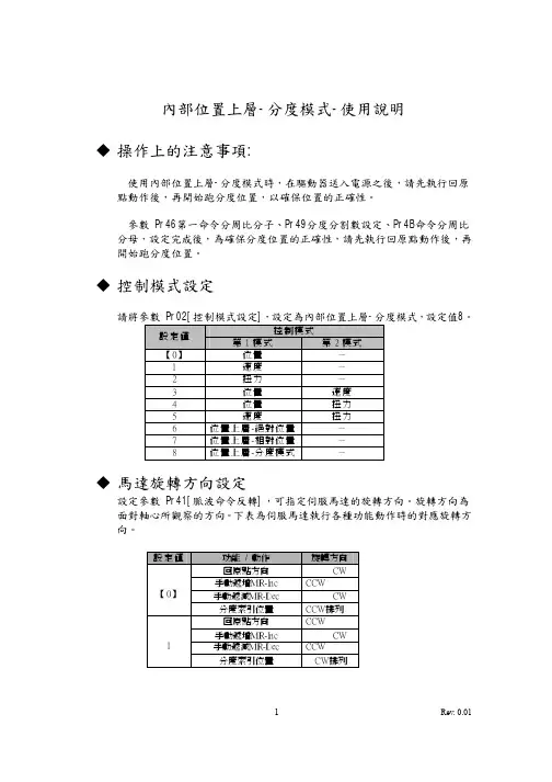
內部位置上層-分度模式-使用說明u操作上的注意事項:使用內部位置上層-分度模式時,在驅動器送入電源之後,請先執行回原點動作後,再開始跑分度位置,以確保位置的正確性。
參數 Pr46第一命令分周比分子、Pr49分度分割數設定、Pr4B命令分周比分母,設定完成後,為確保分度位置的正確性,請先執行回原點動作後,再開始跑分度位置。
u控制模式設定請將參數 Pr02[控制模式設定],設定為內部位置上層-分度模式,設定值8。
控制模式設定值第1模式第2模式【0】位置-1 速度-2 扭力-3 位置速度4 位置扭力5 速度扭力6 位置上層-絕對位置-7 位置上層-相對位置-8 位置上層-分度模式-u馬達旋轉方向設定設定參數 Pr41[脈波命令反轉],可指定伺服馬達的旋轉方向。
旋轉方向為面對軸心所觀察的方向。
下表為伺服馬達執行各種功能動作時的對應旋轉方向。
設定值功能/ 動作旋轉方向回原點方向CW手動遞增MR-Inc CCW【0】手動遞減MR-Dec CW分度索引位置CCW排列回原點方向CCW手動遞增MR-Inc CW1手動遞減MR-Dec CCW分度索引位置CW排列u I/F接線圖相輸出相輸出相輸出u I/F接腳信號與位準定義Pin No. 腳位定義1 功能1 腳位定義2 功能2 位準1 PosBit6+ 分度點選擇6(+) A接點2 PosBit5+ 分度點選擇5(+) A接點34 PosBit6- 分度點選擇6(-) A接點56 PosBit5- 分度點選擇5(-) A接點7 COM+ 信號電源(+)8 Origin 原點Sensor 輸入B接點9 E-STOP 緊急停止輸入A接點10 BK-OFF- 解除煞車(-) DO1- 狀態編碼1(-) 輸出11 BK-OFF+ 解除煞車(+) DO1+ 狀態編碼1(+) 輸出12 ZSP 零速度檢知DO2 狀態編碼2 輸出13 GND 類比信號地1415 GND 類比信號地1617 GND 類比信號地1819 CZ Z相信號開集極輸出20 PosBit4 分度點選擇4 輸入A接點21 OA+ A相信號(+) 輸出22 OA- A相信號(-) 輸出23 OZ+ Z相信號(+) 輸出24 OZ- Z相信號(-) 輸出25 GND 類比信號地26 MR-Step 手動移動-單步MR-Dec 手動單步-遞減輸入B接點/ A接點27 MR-Con 手動移動-連續MR-Inc 手動單步-遞增輸入B接點/ A接點28 PosBit3 分度點選擇3 輸入A接點29 SVO-ON 馬達通電激磁輸入A接點30 PosBit2 分度點選擇2 輸入A接點31 FuncBit1 分度功能1 輸入A接點32 FuncBit2 分度功能2 輸入A接點33 PosBit1 分度點選擇1 輸入A接點34 SVO-RDY- 伺服系統待命(-) DO3- 狀態編碼3(-) 輸出35 SVO-RDY+ 伺服系統待命(+) DO3+ 狀態編碼3(+) 輸出36 SVO-ALM- 伺服異常警報(-) DO4- 狀態編碼4(-) 輸出37 SVO-ALM+ 伺服異常警報(+) DO4+ 狀態編碼4(+) 輸出38 ON-POS- 位置完成(-) DO5- 狀態編碼5(-) 輸出39 ON-POS+ 位置完成(+) DO5+ 狀態編碼5(+) 輸出40 TLC 扭力極限檢知DO6 狀態編碼6 輸出41 COM- 信號電源(-)42 IM 扭力監視輸出43 SPM 速度監視輸出4445464748 OB+ B相信號(+) 輸出49 OB- B相信號(-) 輸出50 FG 大地接地u分度控制輸入設定1.自動索引模式執行回原點、分度點移動前,控制接腳請先輸入扭力限制動作後,再輸入回原點或分度點移動。
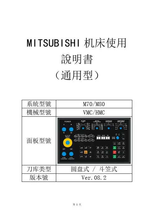
MITSUBISHI机床使用說明書(通用型)系統型號M70/M80機械型號VMC/HMC面板型號刀库类型圆盘式 / 斗笠式版本號Ver.08.2目錄第一章機床使用前注意事項1.1 電氣規範第一次啟動前注意事項機床用電安全機床操作注意事項1.2 機床接地及注意事項1.3 開機/關機順序開機操作順序關機操作順序機械原點複歸2.4 緊急停止及恢復第二章操作面板2.1 機械操作面板外觀圖2.2 機械操作面板功能說明A. 電源及緊急停止區B. 模式選擇區C. 軸的移動以及速度/倍率選擇區D. 主軸控制區E. 自動操作功能區F. 周邊功能區G. 警示燈區H. 指示燈區第三章M功能代碼表第四章異警排除附錄 A ATC設定與調整A、刀臂式刀庫ATC調整1. Z軸換刀點的調整2. 主軸定位點的調整3. 刀庫分解動作說明B、斗笠式刀庫ATC調整1. Z軸換刀點的調整2. 主軸定位點的調整C、刀具表重新排列步驟附錄 B I/O列表附錄 C 掃描面板地址表第一章機床使用前注意事項1.1 電氣規範本機床目的是用於金屬切削。
例如銅、鐵、不銹鋼、鋼、鋁以及鋁合金屬。
其他金屬或用途是不允許的。
而且不適合使用在易燃物質或硬脆材質如鎂、陶瓷、木頭、玻璃和有毒物質等。
假如有任何標準問題,為了防止人員的安全和保障貴公司的權益,請和本公司聯絡。
第一次啟動前注意事項●操作前請仔細閱讀本書和數控系統的使用手冊●由於經過運輸過程中的顛簸,拆箱後請先檢查XYZ三向的運輸固定裝置是否完好,檢查主軸箱與配重錘之間的連接件是否牢固可靠。
●在機床運行之前,必須檢查XYZ三向及主軸箱和配重錘的運輸固定架和固定螺釘是否已全部拆除。
●首次啟動機床或停用較長時間後,再次啟動機床時,打開電源後,應等待15分鐘,待機床充分潤滑後,再操作機床。
●在機床首次使用前,必須將主軸打刀用增壓缸的油杯注滿液壓油,並排除缸體中的氣體,以確保打刀的可靠性及打刀力,從而避免損傷機床及人員。

第1页,共16页用户手册前言注意: 使用前请详细阅读本用户手册及所搭配的缝制设备说明书,配合正确使用,并须由接受过专业培训的人员来安装或操作。
本产品仅适用于指定范围的缝制设备,请勿移做其他用途。
本公司拥有对此用户手册的最终解释权。
使用中若存有任何疑问或对我们的产品及服务有任何意见或建议,请随时与我们联系。
安全说明1) 安装和调试前,请仔细认真地阅读本手册。
2) 本手册中标有符号之处为安全注意点,必须特别注意并严格遵守,以免造成不必要的损害。
3) 本产品须由受过专业培训的人员来安装或操作。
4) 确保电源安全接地并符合产品铭牌上标示的电压范围及技术要求。
5) 接通电源开关时,请把脚离开脚踏板。
6)在进行以下操作时,必须先断开系统电源:■ 安装机器时;■ 在控制箱上插拔任何连接插头时; ■ 穿针线,换机针及翻抬机头时; ■ 机器休息不用及修理或调整时。
7)拧紧所有紧固件,以防止缝制作业时产生振动或停针位置错位等异常现象。
8)每次关闭控制系统后再次启动,应相隔30秒以上。
9)设置系统控制参数或进行保养修理工作应由受过相关培训的专业人员来完成。
10)维修所用的所有零部件,必须由本公司提供或认可,方能使用。
11)接地线的安装(特别注意)。
注意: 安装控制器时必须正确接地,否则将导致控制器无法正常工作,更严重的可能会被电击(详见安装章节)。
1.产品介绍1.1 概述此系列工业缝纫机数控交流伺服系统,电机与控制器分体吊装,使配置组合灵活方便,电机与控制器可按需搭配,实现多种缝纫机对功率、速度等的配套要求;安装简易、调整便捷、力矩大、体积小、噪音低、效率高(省电!);采用开关电源供电,使其具有更宽的电压适配范围;避免油渍污染引起的控制器故障;优化交流伺服电机控制策略,使转速控制精度高;软硬件双重保护功能使系统工作更可靠。
人机界面使参数调节更方便,使用更具灵活性。
专利设计的吊装方式使安装更简捷,整体震动降至最低,系统运行更平稳;1.2基本参数此系列数控交流伺服系统的基本参数详见表1。

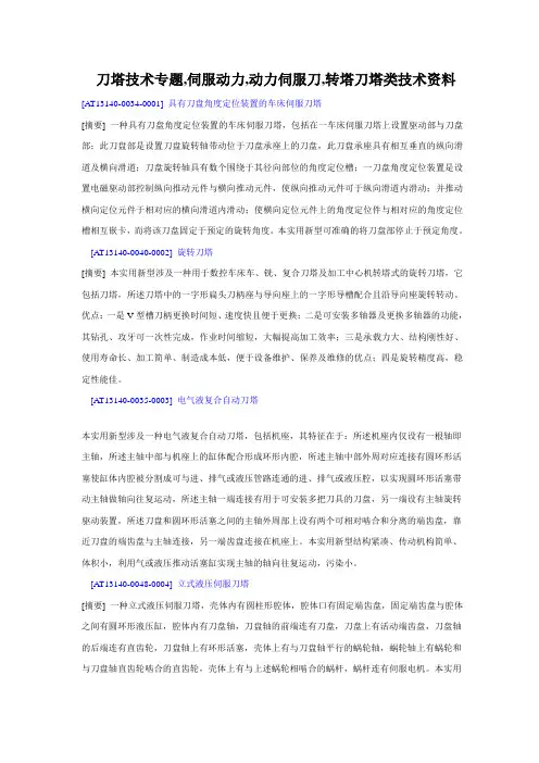
刀塔技术专题,伺服动力,动力伺服刀,转塔刀塔类技术资料[AT13140-0034-0001] 具有刀盘角度定位装置的车床伺服刀塔[摘要] 一种具有刀盘角度定位装置的车床伺服刀塔,包括在一车床伺服刀塔上设置驱动部与刀盘部;此刀盘部是设置刀盘旋转轴带动位于刀盘承座上的刀盘,此刀盘承座具有相互垂直的纵向滑道及横向滑道;刀盘旋转轴具有数个围绕于其径向部位的角度定位槽;一刀盘角度定位装置是设置电磁驱动部控制纵向推动元件与横向推动元件,使纵向推动元件可于纵向滑道内滑动;并推动横向定位元件于相对应的横向滑道内滑动;使横向定位元件上的角度定位件与相对应的角度定位槽相互嵌卡,而将该刀盘固定于预定的旋转角度。
本实用新型可准确的将刀盘部停止于预定角度。
[AT13140-0040-0002] 旋转刀塔[摘要] 本实用新型涉及一种用于数控车床车、铣、复合刀塔及加工中心机转塔式的旋转刀塔,它包括刀塔,所述刀塔中的一字形扁头刀柄座与导向座上的一字形导槽配合且沿导向座旋转转动。
优点:一是V型槽刀柄更换时间短、速度快且便于更换;二是可安装多轴器及更换多轴器的功能,其钻孔、攻牙可一次性完成,作业时间缩短,大幅提高加工效率;三是承载力大、结构刚性好、使用寿命长、加工简单、制造成本低,便于设备维护、保养及维修的优点;四是旋转精度高,稳定性能佳。
[AT13140-0035-0003] 电气液复合自动刀塔本实用新型涉及一种电气液复合自动刀塔,包括机座,其特征在于:所述机座内仅设有一根轴即主轴,所述主轴中部与机座上的缸体配合形成环形内腔,所述主轴中部外周对应连接有圆环形活塞使缸体内腔被分割成可与进、排气或液压管路连通的进、排气或液压腔,以实现圆环形活塞带动主轴做轴向往复运动,所述主轴一端连接有用于可安装多把刀具的刀盘,另一端设有主轴旋转驱动装置,所述刀盘和圆环形活塞之间的主轴外周部上设有两个可相对啮合和分离的端齿盘,靠近刀盘的端齿盘与主轴连接,另一端齿盘连接在机座上。
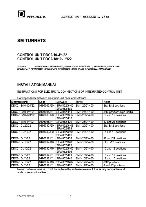
SM-TURRETSCONTROL UNIT DDC2-10-J**/22CONTROL UNIT DDC2-18/10-J**/22Software: SFW062G402, SFW062G403, SFW062G406, SFW062G412, SFW062I403, SFW062I406,SFW062I412, SFW062I421, SFW062I429, SFW062I438, SFW062I439, SFW062I444, SFW062I445INSTALLATION MANUALINSTRUCTIONS FOR ELECTRICAL CONNECTIONS OF INTEGRATED CONTROL UNITCorrespondence between electronic unit code and softwareElectronic unit Code Software Turret NotesDDC2-18/10-J20/220496066J20SFW062G402SM-*-25/2*-400Std. 8/12 positionsSFW062I402DDC2-18/10-J**/220496066J**SFW062I444SM-*-25/2*-4008/12 positions high inertiaSM-*-25/2*-400 6 and 12 positions DDC2-18/10-J20/220496066J20SFW062G412SFW062I412DDC2-18/10-J**/220496066J**SFW062I439SM-*-25/2*-40012 and 24 positionsSM-*-20/2*-400Std. 8/12 positionsDDC2-10-J20/220496032J20SFW062G403SFW062I403SM-*-20/2*-400 6 and 12 positions DDC2-10-J20/220496032J20SFW062G406SFW062I403DDC2-10-J**/220496032J**SFW062I438SM-*-20/2*-40012 and 24 positions DDC2-10-J16/220496032J16SFW062G403SM-*-16/2*-400Std. 8/12 positionsSFW062I403SM-*-16/2*-400 6 and 12 positions DDC2-10-J16/220496032J16SFW062G406SFW062I406DDC2-10-J**/220496032J**SFW062I421SM-*-16/2*-400 8 and 12 positions DDC2-10-J**/220496032J**SFW062I445SM-*-16/2*-400 8 and 16 positions DDC2-10-J16/220496032J16SFW062G407SM-*-12/2*-4008/12 positionsDDC2-10-J**/220496032J**SFW062I407SM-*-12/2*-4008 and 12 positions Notes: Software release ‘G’ will be replaced by software release ‘I’ that is fully compatible andadds more functionalities.Contents1.GENERAL INFORMATION3CODE OF THE CONTROL UNIT3 IMPORTANT NOTE FOR SAFETY3 EMC COMPLIANCE3 TECHNICAL CARACTERISTICS OF THE CONTROL UNIT42.ELECTRICAL CONNECTIONS5SUPPLY5 POWER SUPPLY 400 VAC 3 Φ5 POWER SUPPLY 230 VAC 2 Φ5 POWER SUPPLY 24VDC FOR I/O5 TECHNICAL SPECIFICATIONS FOR POWER TRANSFORMER DESIGN5 I/O SIGNALS6 OUTPUTS TO CNC6 OUTPUTS TO ELECTROVALVE6 INPUTS FROM CNC6 SELECTION OF THE NUMBER OF POSITIONS6 SELECTION OF LOW/HIGH INERTIA6 SELECTION OF STANDARD/MAINTENANCE SPEED6 CONNECTION BOX AND TERMINALS LAY-OUT7 3.INTERFACING TO CNC8 OPERATING FUNCTIONS8 ZERO SEARCH8 OPERATING FUNCTIONS DESCRIPTION9 OPERATING FUNCTION N°0: EMERGENCY / RESET11 OPERATING FUNCTION N°1,2,3: AUTOMATIC11 OPERATING FUNCTION N°4: JOG12 OPERATING FUNCTION N°5: SERVICE12 OPERATING FUNCTION N°6: MAINTENANCE12 OPERATING FUNCTION N °7: SAFETY13 4.DIAGNOSTIC15 ALARMS AND WARNINGS15 EXTENDED ALARM DESCRIPTION/TROUBLESHOOTING16 The information described in this manual may be subject to variations due to technical modifications. DUPLOMATIC S.p.A. reserves the right to modify the contents of this manual without prior notice.1.GENERAL INFORMATIONThe Duplomatic control unit is a compact system that controls all functions regarding positioning and driving of the SM* turrets Duplomatic.The interfacing to the lathe is powerful and simplified for an easy installation.Serial line RS232 is set for diagnostic and remote control by PC.CODE OF THE CONTROL UNITIt is possible to see all the data concerning the control unit looking at this stamp, applied on its rack.Model:IMPORTANT NOTE FOR SAFETYThe turret has been tested under the condition reported as follows and obtained the compliance for: CEI EN 61800-3 and CEI EN 61800-4.CHARACTERISTICS OF THE CONTROL UNIT TYPE DDC2-10-J**/22•Best path research.•External selection of rotation direction.•Automatic reference search.•Parity control on position code.•Enhanced diagnostic.•Selection of two ranges of positions (eg. 8 and 12 or 6 and 12) with dedicated inputs.•Selection of inertia on disc with dedicated input.•Speed reduction for maintenance purposes with dedicated input.• 'Safety' behaviour can be set by CNC or PC.The entire unit is insulated from the external with optoinsulators to satisfy safety standards.Parameters of the system are optimised and cannot be modified by the customer. TECHNICAL CARACTERISTICS OF THE CONTROL UNITPower supplyPower input 3Φ400V +15% - 10 %50/60Hz ±2Hz 3 Φ10A max.Auxiliary input 2Φ230V±10%50/60Hz ±2Hz 2 Φ35VAtab 1Supply for I/ODigital inputs •Type •Voltage •Current optoinsulated Sink24 VDC ±10%5 mA @ 24 VDCDigital outputs•Type•Voltage•Max current for signals Electrovalve•Type•VoltageMax current for electrovalve Optoinsulated •Transistor NPN (Source)•24 VDC ±10%•0.2A @ 24 VDC Optoinsulated •Transistor NPN (Source)•24 VDC ±10%•0.5A @ 24 VDCtab 2General specificationsOperative Temperature0 ÷ 55 °CHumidity30.. 95%Vibrations4G RMS (for short period)0,5 RMS (continuously) tab 32. ELECTRICAL CONNECTIONSRefer to the annex diagrams:1. : wiring diagram for standard turrets.2. : cables3. : timings4. : instructions for RS-232 serial cableSUPPLYPOWER SUPPLY 400 VAC 3 Φ(see tab1)The control unit requires a three-phase 400 VAC input for the power card.A power contactor on the 400 AC line must be used for emergency stop (see wiring diagram).The 400 VAC line must be protected with external fuses 10 A T.(or 4-6.3 A motor start)An inrush current can happen at power-on due to the internal 100uF power capacitors.An external filter is required to meet E.M.C. compliance (optional).POWER SUPPLY 230 VAC 2 Φ(see tab1)The control unit requires a single-phase 230 VAC input for the logic card.A 500mA T F2 fuse must be used to protect this supply.POWER SUPPLY 24VDC FOR I/O (see tab 2)On the control unit are present two different connections +24VDC.The +24VDC on terminal P10-2 is used to supply the electrovalve and must be protected with a 500 mA T fuse (F5).The +24VDC on terminal P10-6 is used to supply the signals outputs and must be protected with a 500mA FF fuse (F4).0VDC is connected at terminal P10-24.Note: during turret start-up, use P10-1 and P10-7 connections for 24V DC. In this way the fuses inside the connection box are used and can protect the unit against mistakes on wirings. After the positive test switch to P10-2 and P10-6 and use the fuses in the cabinet that are more reachable.TECHNICAL SPECIFICATIONS FOR POWER TRANSFORMER DESIGNImportant: check the voltage drop on the 400 VAC supply during acceleration, to be sure that this doesn’t approach the indicated voltage limits.Rated primary voltage VariableSecondary rated voltage 400 VCA ± 10% 3 ΦRated Power1000 VA Max voltage drop at 10 A rms (during acceleration)5%Connectionstar-star or delta-star Secondary voltage deviation ± 2%tab 4I/O SIGNALSOUTPUTS TO CNCLOCKED: turret locked.INDEXD: turret in position (can be used to start axis movement).ALBIT1, ALBIT2, ALBIT4: alarms code.OUTPUTS TO ELECTROVALVEEVLOCK: locking valve.EVULCK: unlocking valve.INPUTS FROM CNCPBIT01, PBIT02, PBIT04, PBIT08, (PBIT16): position code bits.PARITY: parity for position codes.PSTART: signal for starting turret cycle.PTAB01, PTAB02: set 8/12 positions.PTAB03: set low/high inertia.MODE01, MODE02, MODE03: mode selection code bits.SPDSEL: selection of standard or maintenance speed.SELECTION OF THE NUMBER OF POSITIONSThe turret can be easily configured for two different number of positions simply setting two signals in the control unit. No mechanical operations or part replacement are required Software8/12 tools6/1212/248/16Tools N°8126121224816PTAB0124VDC0VDC24VDC0VDC24VDC0VDC24VDC0VDCPTAB020VDC24VDC0VDC24VDC0VDC24VDC0VDC24VDCThe 24VDC for selections must be done at the same time with 230 VAC 1 Φ (max lag time 500 ms).If the 24 VDC is done with a lag time over 500 ms, the turret can not start and ALARM 78 (or 77) appears.SELECTION OF LOW/HIGH INERTIAThe turret can be easily configured to drive two ranges of inertia just setting a signal in the control unit.No mechanical operations or part replacement are requiredStandard inertia High inertiaPTAB03connected to 24VDC not connectedSELECTION OF STANDARD/MAINTENANCE SPEEDThis input can be used to slow-down immediately the turret in front of dangerous operations (door opening, maintenance operations). The speed is about the 20% of the nominal speed. Connect the SPDSEL input to the 24VDC supply if not used.Standard speed Maintenance speedSPDSEL connected to 24VDC not connectedCONNECTION BOX AND TERMINALS LAY-OUTName Terminal Name Terminal CM2-FUSE-F2P10-1MODE03P10-21 CM2P10-2SPAREINP1P10-22EVLOCK P10-3SPDSEL P10-23EVULCK P10-4COM 0V P10-24SPAREOUT1P10-5PTABO1LK1 CM1P10-6PTABO2LK2 CM1-FUSE-F1P10-7PTABO3LK3 LOCKED P10-8INDEXD P10-9R E1ALBIT1P10-10S E2ALBIT2P10-11T E3ALBIT4P10-12PE E4PBIT01P10-13L E5PBIT02P10-14N E6PBIT04P10-15PBIT08P10-16P9-2RS232-RXDPARITY P10-17P9-3RS232-TXDPSTART P10-18P9-4RS232-DTRMODE01P10-19P9-5RS23-2SGMODE02P10-20P9-7RS232-RTS3.INTERFACING TO CNCOPERATING FUNCTIONSThe control unit offers several operating functions (also called MODES).Setting MODE01, MODE02, and MODE03 signals can make the selection of the operating functions.INPUTS DESCRIPTIONN°OPERATINGFUNCTIONS MODE01MODE02MODE030Emergency/Reset 000Setting this mode will stop immediately the turret. Alarmscan be reset setting this mode and the setting another mode.1Automaticshortest path 100The turret will use the shortest path to reach the positionrequired.2Automatic CW010The turret will always use the CW direction path to reach theposition required.3Automatic CCW110The turret will always use the CCW direction path to reachthe position required.4Jog, next tool inCW or CCW001The turret will reach the next position.5Service101Enables a series of functionality to simplify the start-up phaseand troubleshooting6Maintenance(only by PC)---7Safety111Enables a series of functionality to overcome conditions thatnormally would stop the turret for a long time.ZERO SEARCHAfter any power-on of the control unit (230 V -1 phase auxiliary supply) the turret mustexecute the reference cycle.At the end of the reference cycle the turret is locked in position 1.To execute the reference cycle proceed as follows1. Set an automatic function (1,2 or 3)2. Set this code.POSITION PARITY PBIT01PBITO2PBIT04PBIT08(PBIT16)Zero cycle0000003. Set impulsive PSTART to reach out the zero position(PSTART must stay on for more than 30 ms).4. Wait 500 ms after INDEXD and LOCKED signals give the end of the cycle.AUTOMATIC OPERATING FUNCTIONS (1,2,3)•Set the code of the position required.•Wait until the position code output is stable (it depends on what type of PLC/CNC outputs are used - relay, static…).•Give the PSTART command (active on its rising front). PSTART must stay ON for more than 30 ms (T2).•The turret confirms the reception of the start signal by setting low both INDEXD and LOCKED signal after approximately 30 ms (T3).•When the position requested has been reached, but the disc is not yet locked, the INDEXD signal is set high (this signal can be used to start the approach of the tool to the part to be worked on).•After the disc has been locked, the LOCKED signal is set to high. The turret can work.•Position bits and parity bit must be stable for at least 30 ms. from PSTART signal. After this time and once the turret confirmed the start reception, position bits, parity bit, and start signal can be changed until the INDEXED signal is low. However it is strongly recommended to keep position bits and parity code set to the last position called.•The PSTART signal can be reset after the confirmation of the reception, typically it must stay on for at least 30 ms (T2).Important: the end of cycle must be detected by the LOCKED signal that changes from low to high and with the INDEXD signal high and no alarms are present.SAME TOOL CALLIn case of the turret is already in the position called (for example change in tool offset T1.01 ..T1.02) the turret will not move or unlock/lock but the INDEXD and LOCKED signals will have the same behaviour as a normal rotation (INDEX and LOCKED low after the PSTAR and then after approx. 200ms the INDEX goes HIGH and after 50 ms more the LOCKED signal goes HIGH).INDEXD SIGNALThe INDEXD signal must be used with the LOCKED signal to detect the end of cycle of the turret and can be ignored once the turret is locked.The INDEXD output goes and stay LOW also when the emergency mode is set and if the three-phase power supply is OFF.In this case, if the turret management from PLC/CNC uses the emergency mode or open the power contactor, the INDEXD signal must be used only when the turret is in cycle and then ignored.The CNC/PLC program must check the LOCKED signal while the turret is not in cycle: if this signal goes LOW stop immediately the machine and check the cause.JOG MODEThe turret does not output the position code, so in JOG mode the actual position must be memorised by the CNC / PLC.Be sure to not show in the screen of CNC a tool position different from the reality.We suggest to use always the automatic mode in order to force CNC to keep track of the turret position.ALARM CONDITIONSWhen an alarm condition is detected, one or more of the ALBIT1, ALBIT2, ALBIT4 is high and the INDEXD signal is low.In this case the machine must be immediately stopped and the three-phase power contactor should be opened.Important: the turret can show alarms in any time (also if it is not on cycle) so check always the alarm output of the turret.EXCESSIVE ELECTRICAL NOISE OR BAD WIRING DETECTIONIf the turret is not in cycle and in automatic mode, any variation in POSITION BITS and PARITY must be followed by the PSTART signal.If the PSTART does not came in about 5 seconds (T1) an alarm 7 (73) is output from the turret. Avoid to change the position code just after the turret LOCKED signal goes high (end of cycle) because this can be detected as a new position request.See the diagnostic section to have more details.AUTOMATIC RECOVER FOR PRESSURE/VALVES PROBLEMSThe turret will attempt three times to lock or unlock before giving an alarm (41 or 51).If the operator hear the valve operated more timed during the tool change it is necessary to check the cause of the problem and remove it before a permanent failure happens.OPERATING FUNCTION N°0: EMERGENCY / RESETOPERATING FUNCTION N°0INPUTSMODE01MODE02MODE03 Emergency/reset000This operating function has two purposes:1) Stop all turret movement (EMERGENCY).2) Acknowledge all alarms, if they are present (RESET).It must stay on for more than 30 ms to be read by the control unit. It isn’t necessary to carry out a RESET to go into or out operating function. In any case, if a RESET is executed, it is necessary to wait 800 ms before any variation of signals.The INDEX signal goes low after a RESET.The alarm output will be cleared changing from operating function N°0 to another operating function (e.g. Automatic).OPERATING FUNCTION N°1,2,3: AUTOMATICThese operating functions are normally used to drive the turret.Just set the code of the position required, give the start signal and the turret will automatically reach the position.1. Clear all alarms (if present);2. Set an automatic function:OPERATING FUNCTION N°1,2,3INPUTSMODE01MODE02MODE03 Automatic with shortest path search100Automatic CW010Automatic CCW1103. Set the position code: (use PBIT16 only for turrets with 16 tools or more).POSITIONCODE Zero Cycle123456789101112PBIT010101010101010PBIT020011001100110PBIT040000111100001PBIT080000000011111(PBIT16)0000000000000PARITY0110100110010POSITIONCODE131415161718192021222324PBIT01101010101010PBIT02011001100110PBIT04111000011110PBIT08111000000001(PBIT16)000111111111PARITY1101001011004. Set PSTART for give the confirmation of the movement within 5 s.(It must stay ON for more than 30 ms).OPERATING FUNCTION N°4: JOGThe disc will rotate of one step in the selected direction.Proceed as follows1. Clear all alarms (if present);2. Set the operating function:OPERATING FUNCTION N°4:INPUTSMODE01MODE02MODE03 Next station in CW or CCW0013. Select direction:PBIT01PBIT02Rotation in CW10Rotation in CCW014. Set PSTART for give the confirmation of the movement in 5 s.(It must stay ON for more than 30 ms).OPERATING FUNCTION N°5: SERVICEThe turret cycle can be executed “step by step”: unlocking, rotation, locking.Proceed as follows1. Clear all alarms (if present);2. Set an operating function:OPERATING FUNCTION N°5:INPUTSMODE01MODE02MODE03 Service1013. Select a command:PBIT01PBIT02PBIT04PBIT08PARITY Locking00100Unlocking00010Next tool CW10001Next tool CCW0100110000 Continuos rotationCW01000 Continuos rotationCCW4. Set PSTART for give the confirmation of the movement within 5 s.(It must stay ON for more than 30 ms).Locking and unlocking don’t require PSTART signal.OPERATING FUNCTION N°6: MAINTENANCECan be used to test the functionality of the control unit with RS232 and a special software for Windows on a PC (SERVICE DUPLOMATIC).OPERATING FUNCTION N °7: SAFETYThe standard behaviour of the turret can be changed in order to allow the turret to work even if there are problems mainly on proximity switches.WARNING: all the functions are intended to be used only in case of effective problems. The improper use can cause a damage of the turret or the machine.Proceed as follows:1. Clear all alarms (if present);2. Set the operating function:OPERATING FUNCTION N°7:INPUTSMODE01MODE02MODE03SAFETY1113. Select the operation:n°PBIT01PBIT02PBIT04PBIT08PARITY1Execute the reference cycle (1)1000101001 2Disable the management of unlocking switch:(the unlocking phase is based upon timeinstead that switch output) (2)3Disable the management of locking switch:11000 (the locking phase is based upon time insteadthat switch output) (2)00101 4Assume the actual position of the disc asposition number 1 and disable themanagement of reference switch (3)5Apply a speed reduction of 30%1010001100 6Disable the management of the thermaldetector of the motor (4) (only SW rel ‘I’)7Toggle ON/OFF the output of the second digit11101 of the last alarm. (5) (only SW rel ‘I’)8Toggle ON/OFF the serialize mode (6)00011 (only SW rel ‘I’)10010 9Toggle ON/OFF the output of the status of theswitches (7) (only SW rel ‘I’)10Enable the autotest function (8)01010 (only SW rel ‘I’)15Reset to standard functionality111104. Set the PSTART signal two times (with a pause of about 50ms. between the two pulses)without changing the code pattern to activate the function required.IMPORTANT: there is no confirmation about the correct execution of the operation, because this is intended as a manual operation with effect that can be easily verified by operator.All functionality set by this mode will be automatically reset at the power-off of the control unit. (1) This is an alternative way to execute the reference cycle in CNC in which the tool T 0 is notallowed. In this case only one PSTART is required.(2) In this case we assume that the turret is surely locked or unlocked in about 400 ms.(3) Be sure that the disc is really in position 1, elsewere this operation could be dangerous.This function can be performed only if the reference cycle has not yet been executed.(4) Please be sure that thermal detector is broken otherwise this could damage the servomotor.(5) The second digit of the alarm code is output on the ALBIT1..ALBIT4. A reset will turn-off thisfunction.(6) In this case a slow SSI - like protocol (Serial Synchronous Interface) is enabled using theALBITs outputs.SIGNAL READY CLOCK DATAOUTPUT ALBIT1ALBIT2ALBIT4The READY signal is independent an is ON if the turret is OK.Byte 2:Turret Position (0-> turret out of position; <>0 turret is/can be locked on theposition )Byte 3: Digital inputs 1:In order (ZEROSW,ULCKSW,LOCKSW, MOTVL,PTAB03,MOD03,MOD02,MOD01)Byte 4: Digital inputs 2:In order (PTAB02,PTAB01,PSTART,PARITY,PBIT08,PBIT04,PBIT02,PBIT01)(7) The status of the switches of the turret is output as follows:SIGNAL MOTOVL(thermal detector)ZEROSW(reference)LOCKSW(locking)ULCKSW(unlocking)OUTPUT INDEXD ALBIT1ALBIT2ALBIT4A reset will disable this function.(8) Danger of collision to other parts of the lathe! Move the turret in a safe zone befor startingthe cycle. The autotest function is stopped and disabled by putting the turret in emergency mode (MODE 0).()4.DIAGNOSTICALARMS AND WARNINGSThe electronic unit constantly executes self-diagnosis and can signal alarms condition.Alarm code is provided on output ALBIT1, ALBIT2, ALBIT4 according to the following table.ALARM CODE ALARM N°DESCRIPTION ALBIT1ALBIT2ALBIT41001Fault of supply.0102Over voltage.1103Over current/servo error/thermal detector.0014Unlocking faults,(switch fault, setting, pressure supplyfault, etc.).1015Locking faults,(switch fault, setting, pressure supplyfault, etc.).0116Zero search fault,(switch fault, setting, etc.).1117Zero search missed/Position code error/Cycle time out/PSTART signal time out.Alarm are stored and can be reset with EMERGENCY/RESET function.Power off causes the reset of the active alarm.A better identification of the alarm codes is possible by a PC with RS232 interface and a Duplomatic diagnostic software. availablePlease refer to the EXTENDED ALARM DESCRIPTION to get a more complete description of the alarm and to have information about troubleshooting.Serial communication parameters (for software ‘G’): 9600,N,8,1.Serial communication parameters (for software ‘I’): 9600,E,8,1 or 9600,N,8,1.Fault of electronic unit:After recognizing the fault, the problem can be easily solved.In case of electronic unit fault, it can be easily replaced.EXTENDED ALARM DESCRIPTION/TROUBLESHOOTINGDescriptionALARMCODE10Fault in internal supply: check the 230 V auxiliary supply.11Drop on the Three-Phase voltage during tool change. Check the Three-Phase voltage. (only SW rel I) 20Overvoltage:- Check all external three-phase supplies.21Overvoltage reached during dynamic braking:-the inertia loaded on disc is too high: check that the configuration signal (PTAB03 -LK3 on connection board)is set to the proper inertia range.-Check that the Three-Phase voltage is not over specs.-Fault on internal dynamic braking circuit.30Motor Overcurrent (absorbed current too high):-short on motor phases, or in wiring between DDC and motor31Overload (mean current too high):-inertia loaded on disc exceeds limits (check that the turret is set to the right inertia value by the PTAB03signal – LK3 on connection box);-the unbalanced load exceeds limits;-crash during disc rotation;-zero switch or zero cam are not well positioned (if the alarm happen when the turret is locking at thereference cycle completion;-wiring to the motor or the resolver is defective.-mechanical hardening32Following error:-inertia loaded on disc exceeds limits (check that the turret is set to the right inertia value by the PTAB03signal – LK3 on connection box);-the unbalanced load exceeds limits;-the tool touch the piece slowly during disc rotation;-the wiring to the resolver is defective.33The time limit to execute the cycle has been reached:-the tool touch the piece slowly at the end of the cycle so cannot reach the final position;35The thermal detector of the motor :-indexing frequency too high;-defective motor;-the thermal detector is not connected.36The reference cam is not in the expected position. (only SW rel I)40The signal of the locking switch stays on during the unlocking phase:-unlocking pressure too low;-bad position of locking switch;-bad switch connection/wiring (remote application mainly);-the locking switch is defective.41The signal of the unlocking switch stays off during the unlocking phase:-unlocking pressure too low;-bad position of locking switch;-bad switch connection/wiring (remote application mainly);-the locking switch is defective.42The signal of the unlocking switch goes off while the turret is unlocked:-problems of pressure;-bad switch connection/wiring (remote application mainly);-the unlocking switch is defective.43The signal of the locking switch goes on while the turret is unlocked:-problems of pressure;-bad switch connection/wiring (remote application mainly);-the locking switch is defective.44The turret is unlocked at power-on:-the electrovalve is defective or positioned in such a way that the internal part can move without command(vertical);45The two pressure inlet or the LOCKED and UNLOCKED switches are reversed. (only SW rel I)ALARMDescriptionCODE50The signal of the unlocking switch stays on during the locking phase:-locking pressure too low (only hydraulic);-bad position of unlocking switch;-bad switch connection/wiring (remote application mainly);-the unlocking switch is defective.51The signal of the locking switch stays off during the locking phase:-locking pressure too low (only hydraulic);-bad position of locking switch;-bad switch connection/wiring (remote application mainly);-wrong control unit code (card for a different size);-wrong reference cam regulation (turret lock over teeth);-the locking switch is defective.52The signal of the locking switch goes off while the turret is locked:-problems of pressure (only hydraulic);-bad switch connection/wiring (remote application mainly);-the locking switch is defective.53The signal of the unlocking switch goes on while the turret is locked:-problems of pressure (only hydraulic);-bad switch connection/wiring (remote application mainly);-the unlocking switch is defective.55The two pressure inlet or the LOCKED and UNLOCKED switches are reversed. (only SW rel I) 60Time-out in reference cam search:-the zero switch is defective (always off);-the position of the reference cam is wrong.-bad switch connection/wiring (remote application mainly);-the disc cannot rotate.61Time-out in fine reference search:-the zero switch is defective (always on);-bad switch connection/wiring (remote application mainly);-the disc cannot rotate.70 A tool is called before executing the zero cycle:-error in programming logic of CNC;-the operator did not call the reference cycle.71Parity Error in position code:-error in programming logic of CNC;-problems on wiring (PBIT** and PARITY)-slow outputs of CNC/PLC (the output value van be incorrect when the PSTART signal is given)72 A tool non existing has been called:-error in CNC programming;-turret not correctly configured (check the number of positions set by PTAB01 and PTAB02 signals - LK1and LK2 in connection box);-wiring problems.73 A variation in position code has been detected but the PSTART signal is not arrived in within 5 seconds:-error in CNC programming;-wiring problems (PSTART signal not connected).74The time limit of continuos rotation of disc has been reached:-the turret has been activate in maintenance mode or service for long time;-the indexing frequency is too high.78 or 77The configuration input signals PTAB01 and PTAB02 are not configured (number of positions):-error in PTAB01 and PTAB02 setting (LK1 and LK2 in connection box);-the 24 V DC supply is delayed for more than 500 ms in respect of the 230 V AC auxiliary supply (theconfiguration has not been loaded correctly).Note: the code number is memorised by the control unit and can be read with a Duplomatic diagnostic software installed on a PC with the RS232 interface.。
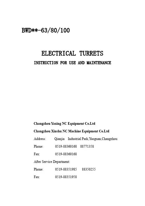
BWD**-63/80/100ELECTRICAL TURRETS INSTRUCTION FOR USE AND MAINTENANCEChangzhou Yaxing NC Equipment Co.LtdChangzhou Xinshu NC Machine Equipment Co.LtdAddress: Qianjia Industrial Park,Yaoguan,ChangzhouPhone: *************88771358Fax: *************After Service Department:Phone: *************88350255Fax: *************1 GENERAL RULES1.1 The tool turrt YAXING design are provided for being incorporated in numerrical controlled turning machines,and they must be used only for this purpose。
The maximum performances of the are shown on of the turret relieves YAXING of any responsibility for possible injury to persons and damage to property to and will also invalid any obligation for warranty.1.2 Befory installing and commissioning the turret,technician and the operator must have read carefully this instruction Manual.1.3 Commissioning adjustment and repair of the turret must be carride out by skilled and authorized personnel who must follow the instructions in this Manual for all necessary steps.1.4 YAXING declines any responsibility for any accident or injuries to persons or damages to property due to non observance of the respective safety rules and to the instruction shown in this Manual.2 ApplicationThis turret is a core of economic and advanced NC lathe.Itmake sure the woikpiece can be automatically processed from turning internal 、 exrernal and turing surface 、 arc to threading 、 groove just by once clamping 、 and widely used for machine tool 、auto 、gear 、bearing 、metallurgy insustry etc.3 Model identification4 Technical data5 DimensionNote:Can be made according to your demands6 Turret indexing sequenceIndexing signal-----motor rotating in CW----NC received locating signal from turret ----stoped motor in CW and restarted motor in CCW----clamping ----stoped motor----detected the clamping signal and response signal ----working.7 Sequence diagramBWD HALL Coder Sequence DiagramBWD8421 Coder Sequence Diagram8 Electrical connection8.1 Motor connectionThe signaling device composed of hall coder and optical coder8.2.1The connection of the hall coder8 STATION TURRET6 STATION TURRET8.2.2 The connection of the 8421 coder8.2.3 explain8.2.3.1 The clamping signal is from the clamping proximateof the turret and the clamping proximate is the NC PNP switch and it is high lever effective and it’s output current is 200mA。
51-5-9002:行發 01.0V:本版 51-5-9002:行發 01.0V:本版 51-5-9002:行發 01.0V:本版 51-5-9002:行發 01.0V:本版司公限有份股電精元東 司公限有份股電精元東 司公限有份股電精元東 司公限有份股電精元東列系TTST 列系TTST 列系TTST 列系TTST東元伺服刀塔專用手冊71.P 71.P 71.P 71.P 51.P 3 31.P 21.P 21.P 21.P 21.P 8.P 8.P 8.P 8.P 7.P 4.P 4.P 4.P 4.P 2.P 2.P 2.P 2.P 1.P 1.P 1.P 1.P件配.9 件配.9 件配.9 件配.9 息訊報警.8 圖序時.7 時 圖程流定設塔刀.6 圖程流定設塔刀.6 圖程流定設塔刀.6 圖程流定設塔刀.6 明說定設數參.5 明說定設數參.5 明說定設數參.5 明說定設數參.5 圖腳接路電.4 明說格規器動驅.3 明說格規器動驅.3 明說格規器動驅.3 明說格規器動驅.3 明說格規達馬.2 明說格規達馬.2 明說格規達馬.2 明說格規達馬.2 項事意注.1 項事意注.1 項事意注.1 項事意注.1錄目 錄目 錄目 錄目-1-1-1-1-。
作動此做須無用使續後,認確做需時用使次一第在作動上以.SP~~ 。
作動此做須無用使續後,認確做需時用使次一第在作動上以.SP~~ 。
作動此做須無用使續後,認確做需時用使次一第在作動上以.SP~~ 。
作動此做須無用使續後,認確做需時用使次一第在作動上以.SP~~ 成完 NO FFO源電.4 成完 NO FFO源電.4 成完 NO FFO源電.4 成完 NO FFO源電.4 1 為定設920nC將 10000為定設920nC將.3 NO FFO源電.2 NO FFO源電.2 NO FFO源電.2 NO FFO源電.2 )表照對 頁9.P( )表照對 頁9.P( )表照對 頁9.P( )表照對 頁9.P( 值定設配匹到定設030nC將.1 值定設配匹到定設030nC將.1 值定設配匹到定設030nC將.1 值定設配匹到定設030nC將.1 定設做需確正不若 0330H:為應值定設030nC 0330H:為應值定設030nC 0330H:為應值定設030nC 0330H:為應值定設030nC )表照對 頁9.P( )表照對 頁9.P( )表照對 頁9.P( )表照對 頁9.P( 1-A5N3-B20131BST:為號型達馬買購 1-A5N3-B20131BST:為號型達馬買購 1-A5N3-B20131BST:為號型達馬買購 1-A5N3-B20131BST:為號型達馬買購 :如例 :如例 :如例 :如例 值定設數參看觀 030nC 式模入進 :下如作操 :下如作操 :下如作操 :下如作操 。
Registered in England: 2486532Registered Office: Richmond House, Walkern RoadStevenage, Herts, SG1 2AJPlant & Equipment List 16/7/21PremisesOperating from a modern 6,600 sq ft factory, fully alarmed including 24-hour CCTVsurveillance. Air-conditioned offices and inspection facility operating to BSI QualityManagement System and ISO 9001:2015 approval. CNC Machining CentresAll the machines listed are DNC linked and programmed using OneCNC XR8 expert full 3D system or "Visicam" CAM system.Doosan DNM 400 Direct drive spindle power 18.5KW, 12,000 rpm spindle, 40 position tool charger, grease lubricated roller, travels 520 X 400 X 480mm with rapid rates of 48m/min on all axes.Doosan DNM 500 Full 4 axis Machine with 12,000 rpm spindle, 15HP spindle motor count, coolant spindle. Travel (X) 40” (Y) 21.25” (Z) 20” Renishaw OMP 60 Spindle probing systemDoosan DNM 5700 Simultaneous 4 axis machining centre, 12,000 rpm spindle speed, spindle motor power 18.5 KW with a tooling taper of 40. Fast tool change, spindle thermal error compensation function for stable cutting, travel (X) 1050 (Y) 570 Z) 510mm. Renishaw OMP 60 Spindle probing system.Daewoo Mynx 500 1m travel. Machining Centre X1020 Y514 Z775, refrigerated Spindle, 8000 rpm, 1.5 second pre-select tool change, swarf conveyor, tool breakage detection/offset probing, rigid tapping, box way machine for heavier / larger work.Fadal VMC 4020 Full 5 axis machine, 10,000 rpm spindle, refrigerated spindle & ball screws, X1000, Y500, Z508, high speed 3D machining facility, tool breakage Renishaw OMP / MP10 spindle probing system, rigid tapping.Haas VF4 Super speed machining centre 1.5m travel Machining centre, full 4th Axis capability, light work, super speed high productivity machine.CNC Turning EquipmentDoosan Lynx 220LMSA Twin spindle driven tooling lathe with long bed, Hydrafeed MV65 magazine bar feed, Max Turning Dia 300mm x 510mm. Fanuc control with manual guide programming.Doosan Lynx 220LSYC 5 axis twin spindle driven tooling lathe with Y and C axis machining, Hydrafeed MV65 magazine bar feed, Max Turning Dia 300mm x 510mm. Fanuc control with manual guide programming.Mori Seiki CL25 Turning Centre 25 Kilowatt main spindle drive motor, for machining difficult materials such as stainless steels up to 300mm diam. Fitted with Renishaw LT02 Job contact inspection probing, Heavy box way machine for heavier / larger work.Daewoo Lynx 200B Turning Centre (bar fed) Fanuc control, chucking diam up to 200mm 2" / 50mm bar capacity. Hydrafeed 3m magazine bar feed, automated tool offset measurement, parts catcher. Wire ErodingAGIE CLASSIC 25 axis CNC wire erosion machine. X 350mm, Y 250mm, Z 256mm, max taper 30 degrees. Max workpiece dimensions 750mmx550mmx250mmConventional Services* Bridgeport Turret & Jig Milling (with DRO)*Colchester Centre Lathe Turning to 15" swing* Jones & Shipman 540Surface Grinding*Range of Drilling & Specialist tapping facilities* Diprofil Die Polishing* Horizontal Bandsaw, semi-automatic cutting, with capacity up to 250mm* Welding: Kemppi Miniarc Mig– Aluminium / Stainless steels / Steel weldingSurface FinishingVapormatt Cougar Bead / Vapour blast part finishing cabinet (wet), 1 metre x 1 metre x 1 metre Vapormatt Lynx Vapour blast machineCAM / Production SoftwarePegasus Operations II production and inventory control with MRP.OneCNC XR8 Full 3D system milling and turning up to 5 axes and twin spindle programming.Visi Cam Mill / Turn 5 with surface modelling 3D interfaceN-See virtual CNC program verification with solid modelling softwareDNC link to all machining centres. File transfer including IGES / DXF (2D or 3D) CATIA, Solidworks, etc.Inspection EquipmentFully air-conditioned, dedicated inspection department, all gauging is calibrated and traceable to NAMAS standards. Quality control systems operate under BSI Quality Management System ISO 9001:2015 approval.DEA Global 2105 CNC Co-Ordinate measuring machine large capacity X700mm Y1000mm Z500mm, with full CNC control and QCT Inspect 3D PRO software, Renishaw motorized PH10 auto index probing system, with MCR20 6 station probe rack.Zeiss Universal Microscope measuring machine, measuring accuracy better than 0.0005mm. Rotary axis facility, enables measuring of large diameter screw cut items, helical milling etc.,Verdict Trimos 500A Digital Height gauge (granite table).Talysurf Surface measuring equipment.Taylor Hobson S100 series Digital surface measuring equipmentSmall Inspection equipment A full range of supporting equipment including plug gauges, screw plug gauges, Vernier calipers, micrometers etc.。
VDF DUS 系列VDF DUS 车削机床用于单件或小批量生产不用再找了。
这里是你能找到的性价比最优的万能数控车床。
VDF Boehringer DUS 系列车床应用广泛。
多种机床型号和大量的选项配置适应广泛的解决方案, 充分满足您的的技术要求,即使是在特殊的应用情况下也具有最优的性价比。
VDF DUS 系列无可置疑的质量2 | VDF Boehringer由于自动循环控制和手动操作的可行性,VDF DUS 系列机床主要用于单件或小批量生产。
自动刀塔和第二个防护门的组合配置,可以进行数控自动加工。
因此在中等批量生产中也具有高效率,可以替代全数控CNC车床。
VDF 560 / 630 DUSVDF 800 / 1000 / 1110 DUS带宽大向后排屑槽的重型刚性盒式床身是高车削效率和保持长期精度的基础3 3 3 33 3 3 3 VDF Boehringer | 3滑台(双 V )和尾座(V 和平面)导轨是成熟的组合。
宽大导轨表面压强低,确保在长期定位精度和重复定位精度情况下高效率导向 。
为避免热量传递影响, 主轴和齿轮箱隔热分开布置。
主轴轴承和高标准的 VDF Boehringer CNC 车床相同。
VDF 400 DUS最小的机床也有最佳表现VDF DUS 系列机床提供高精度和低成本的加工工件的所有先决条件。
4 | VDF Boehringer3 V DF DUS 系列机床在各个方面符合人体工程学设计, 对于操作者加工高精度工件的能力无任何限制。
3机床功能外罩为操作者和环境提供了最佳的安全防护。
转动操作控制面板。
非随行防护门Parat刀塔VDF Boehringer | 5技术参数VDF 400 DUS车削长度 mm 1000回转直径,床身/滑台mm420 / 235横向滑台行程 mm 250刀具截面尺寸, DIN 770 h x wmm25 x 25技术参数Parat刀塔及镗刀杆座Multifix 刀塔VDF 560 / 630 DUS人性化设计获得高生产率3 符合人体工程学的电子手轮布置,堪称艺术设计标准。
SM-TURRETSCONTROL UNIT DDC2-10-J**/22CONTROL UNIT DDC2-18/10-J**/22Software: SFW062G402, SFW062G403, SFW062G406, SFW062G412, SFW062I403, SFW062I406,SFW062I412, SFW062I421, SFW062I429, SFW062I438, SFW062I439, SFW062I444, SFW062I445INSTALLATION MANUALINSTRUCTIONS FOR ELECTRICAL CONNECTIONS OF INTEGRATED CONTROL UNITCorrespondence between electronic unit code and softwareElectronic unit Code Software Turret NotesDDC2-18/10-J20/220496066J20SFW062G402SM-*-25/2*-400Std. 8/12 positionsSFW062I402DDC2-18/10-J**/220496066J**SFW062I444SM-*-25/2*-4008/12 positions high inertiaSM-*-25/2*-400 6 and 12 positions DDC2-18/10-J20/220496066J20SFW062G412SFW062I412DDC2-18/10-J**/220496066J**SFW062I439SM-*-25/2*-40012 and 24 positionsSM-*-20/2*-400Std. 8/12 positionsDDC2-10-J20/220496032J20SFW062G403SFW062I403SM-*-20/2*-400 6 and 12 positions DDC2-10-J20/220496032J20SFW062G406SFW062I403DDC2-10-J**/220496032J**SFW062I438SM-*-20/2*-40012 and 24 positions DDC2-10-J16/220496032J16SFW062G403SM-*-16/2*-400Std. 8/12 positionsSFW062I403SM-*-16/2*-400 6 and 12 positions DDC2-10-J16/220496032J16SFW062G406SFW062I406DDC2-10-J**/220496032J**SFW062I421SM-*-16/2*-400 8 and 12 positions DDC2-10-J**/220496032J**SFW062I445SM-*-16/2*-400 8 and 16 positions DDC2-10-J16/220496032J16SFW062G407SM-*-12/2*-4008/12 positionsDDC2-10-J**/220496032J**SFW062I407SM-*-12/2*-4008 and 12 positions Notes: Software release ‘G’ will be replaced by software release ‘I’ that is fully compatible andadds more functionalities.Contents1.GENERAL INFORMATION3CODE OF THE CONTROL UNIT3 IMPORTANT NOTE FOR SAFETY3 EMC COMPLIANCE3 TECHNICAL CARACTERISTICS OF THE CONTROL UNIT42.ELECTRICAL CONNECTIONS5SUPPLY5 POWER SUPPLY 400 VAC 3 Φ5 POWER SUPPLY 230 VAC 2 Φ5 POWER SUPPLY 24VDC FOR I/O5 TECHNICAL SPECIFICATIONS FOR POWER TRANSFORMER DESIGN5 I/O SIGNALS6 OUTPUTS TO CNC6 OUTPUTS TO ELECTROVALVE6 INPUTS FROM CNC6 SELECTION OF THE NUMBER OF POSITIONS6 SELECTION OF LOW/HIGH INERTIA6 SELECTION OF STANDARD/MAINTENANCE SPEED6 CONNECTION BOX AND TERMINALS LAY-OUT7 3.INTERFACING TO CNC8 OPERATING FUNCTIONS8 ZERO SEARCH8 OPERATING FUNCTIONS DESCRIPTION9 OPERATING FUNCTION N°0: EMERGENCY / RESET11 OPERATING FUNCTION N°1,2,3: AUTOMATIC11 OPERATING FUNCTION N°4: JOG12 OPERATING FUNCTION N°5: SERVICE12 OPERATING FUNCTION N°6: MAINTENANCE12 OPERATING FUNCTION N °7: SAFETY13 4.DIAGNOSTIC15 ALARMS AND WARNINGS15 EXTENDED ALARM DESCRIPTION/TROUBLESHOOTING16 The information described in this manual may be subject to variations due to technical modifications. DUPLOMATIC S.p.A. reserves the right to modify the contents of this manual without prior notice.1.GENERAL INFORMATIONThe Duplomatic control unit is a compact system that controls all functions regarding positioning and driving of the SM* turrets Duplomatic.The interfacing to the lathe is powerful and simplified for an easy installation.Serial line RS232 is set for diagnostic and remote control by PC.CODE OF THE CONTROL UNITIt is possible to see all the data concerning the control unit looking at this stamp, applied on its rack.Model:IMPORTANT NOTE FOR SAFETYThe turret has been tested under the condition reported as follows and obtained the compliance for: CEI EN 61800-3 and CEI EN 61800-4.CHARACTERISTICS OF THE CONTROL UNIT TYPE DDC2-10-J**/22•Best path research.•External selection of rotation direction.•Automatic reference search.•Parity control on position code.•Enhanced diagnostic.•Selection of two ranges of positions (eg. 8 and 12 or 6 and 12) with dedicated inputs.•Selection of inertia on disc with dedicated input.•Speed reduction for maintenance purposes with dedicated input.• 'Safety' behaviour can be set by CNC or PC.The entire unit is insulated from the external with optoinsulators to satisfy safety standards.Parameters of the system are optimised and cannot be modified by the customer. TECHNICAL CARACTERISTICS OF THE CONTROL UNITPower supplyPower input 3Φ400V +15% - 10 %50/60Hz ±2Hz 3 Φ10A max.Auxiliary input 2Φ230V±10%50/60Hz ±2Hz 2 Φ35VAtab 1Supply for I/ODigital inputs •Type •Voltage •Current optoinsulated Sink24 VDC ±10%5 mA @ 24 VDCDigital outputs•Type•Voltage•Max current for signals Electrovalve•Type•VoltageMax current for electrovalve Optoinsulated •Transistor NPN (Source)•24 VDC ±10%•0.2A @ 24 VDC Optoinsulated •Transistor NPN (Source)•24 VDC ±10%•0.5A @ 24 VDCtab 2General specificationsOperative Temperature0 ÷ 55 °CHumidity30.. 95%Vibrations4G RMS (for short period)0,5 RMS (continuously) tab 32. ELECTRICAL CONNECTIONSRefer to the annex diagrams:1. : wiring diagram for standard turrets.2. : cables3. : timings4. : instructions for RS-232 serial cableSUPPLYPOWER SUPPLY 400 VAC 3 Φ(see tab1)The control unit requires a three-phase 400 VAC input for the power card.A power contactor on the 400 AC line must be used for emergency stop (see wiring diagram).The 400 VAC line must be protected with external fuses 10 A T.(or 4-6.3 A motor start)An inrush current can happen at power-on due to the internal 100uF power capacitors.An external filter is required to meet E.M.C. compliance (optional).POWER SUPPLY 230 VAC 2 Φ(see tab1)The control unit requires a single-phase 230 VAC input for the logic card.A 500mA T F2 fuse must be used to protect this supply.POWER SUPPLY 24VDC FOR I/O (see tab 2)On the control unit are present two different connections +24VDC.The +24VDC on terminal P10-2 is used to supply the electrovalve and must be protected with a 500 mA T fuse (F5).The +24VDC on terminal P10-6 is used to supply the signals outputs and must be protected with a 500mA FF fuse (F4).0VDC is connected at terminal P10-24.Note: during turret start-up, use P10-1 and P10-7 connections for 24V DC. In this way the fuses inside the connection box are used and can protect the unit against mistakes on wirings. After the positive test switch to P10-2 and P10-6 and use the fuses in the cabinet that are more reachable.TECHNICAL SPECIFICATIONS FOR POWER TRANSFORMER DESIGNImportant: check the voltage drop on the 400 VAC supply during acceleration, to be sure that this doesn’t approach the indicated voltage limits.Rated primary voltage VariableSecondary rated voltage 400 VCA ± 10% 3 ΦRated Power1000 VA Max voltage drop at 10 A rms (during acceleration)5%Connectionstar-star or delta-star Secondary voltage deviation ± 2%tab 4I/O SIGNALSOUTPUTS TO CNCLOCKED: turret locked.INDEXD: turret in position (can be used to start axis movement).ALBIT1, ALBIT2, ALBIT4: alarms code.OUTPUTS TO ELECTROVALVEEVLOCK: locking valve.EVULCK: unlocking valve.INPUTS FROM CNCPBIT01, PBIT02, PBIT04, PBIT08, (PBIT16): position code bits.PARITY: parity for position codes.PSTART: signal for starting turret cycle.PTAB01, PTAB02: set 8/12 positions.PTAB03: set low/high inertia.MODE01, MODE02, MODE03: mode selection code bits.SPDSEL: selection of standard or maintenance speed.SELECTION OF THE NUMBER OF POSITIONSThe turret can be easily configured for two different number of positions simply setting two signals in the control unit. No mechanical operations or part replacement are required Software8/12 tools6/1212/248/16Tools N°8126121224816PTAB0124VDC0VDC24VDC0VDC24VDC0VDC24VDC0VDCPTAB020VDC24VDC0VDC24VDC0VDC24VDC0VDC24VDCThe 24VDC for selections must be done at the same time with 230 VAC 1 Φ (max lag time 500 ms).If the 24 VDC is done with a lag time over 500 ms, the turret can not start and ALARM 78 (or 77) appears.SELECTION OF LOW/HIGH INERTIAThe turret can be easily configured to drive two ranges of inertia just setting a signal in the control unit.No mechanical operations or part replacement are requiredStandard inertia High inertiaPTAB03connected to 24VDC not connectedSELECTION OF STANDARD/MAINTENANCE SPEEDThis input can be used to slow-down immediately the turret in front of dangerous operations (door opening, maintenance operations). The speed is about the 20% of the nominal speed. Connect the SPDSEL input to the 24VDC supply if not used.Standard speed Maintenance speedSPDSEL connected to 24VDC not connectedCONNECTION BOX AND TERMINALS LAY-OUTName Terminal Name Terminal CM2-FUSE-F2P10-1MODE03P10-21 CM2P10-2SPAREINP1P10-22EVLOCK P10-3SPDSEL P10-23EVULCK P10-4COM 0V P10-24SPAREOUT1P10-5PTABO1LK1 CM1P10-6PTABO2LK2 CM1-FUSE-F1P10-7PTABO3LK3 LOCKED P10-8INDEXD P10-9R E1ALBIT1P10-10S E2ALBIT2P10-11T E3ALBIT4P10-12PE E4PBIT01P10-13L E5PBIT02P10-14N E6PBIT04P10-15PBIT08P10-16P9-2RS232-RXDPARITY P10-17P9-3RS232-TXDPSTART P10-18P9-4RS232-DTRMODE01P10-19P9-5RS23-2SGMODE02P10-20P9-7RS232-RTS3.INTERFACING TO CNCOPERATING FUNCTIONSThe control unit offers several operating functions (also called MODES).Setting MODE01, MODE02, and MODE03 signals can make the selection of the operating functions.INPUTS DESCRIPTIONN°OPERATINGFUNCTIONS MODE01MODE02MODE030Emergency/Reset 000Setting this mode will stop immediately the turret. Alarmscan be reset setting this mode and the setting another mode.1Automaticshortest path 100The turret will use the shortest path to reach the positionrequired.2Automatic CW010The turret will always use the CW direction path to reach theposition required.3Automatic CCW110The turret will always use the CCW direction path to reachthe position required.4Jog, next tool inCW or CCW001The turret will reach the next position.5Service101Enables a series of functionality to simplify the start-up phaseand troubleshooting6Maintenance(only by PC)---7Safety111Enables a series of functionality to overcome conditions thatnormally would stop the turret for a long time.ZERO SEARCHAfter any power-on of the control unit (230 V -1 phase auxiliary supply) the turret mustexecute the reference cycle.At the end of the reference cycle the turret is locked in position 1.To execute the reference cycle proceed as follows1. Set an automatic function (1,2 or 3)2. Set this code.POSITION PARITY PBIT01PBITO2PBIT04PBIT08(PBIT16)Zero cycle0000003. Set impulsive PSTART to reach out the zero position(PSTART must stay on for more than 30 ms).4. Wait 500 ms after INDEXD and LOCKED signals give the end of the cycle.AUTOMATIC OPERATING FUNCTIONS (1,2,3)•Set the code of the position required.•Wait until the position code output is stable (it depends on what type of PLC/CNC outputs are used - relay, static…).•Give the PSTART command (active on its rising front). PSTART must stay ON for more than 30 ms (T2).•The turret confirms the reception of the start signal by setting low both INDEXD and LOCKED signal after approximately 30 ms (T3).•When the position requested has been reached, but the disc is not yet locked, the INDEXD signal is set high (this signal can be used to start the approach of the tool to the part to be worked on).•After the disc has been locked, the LOCKED signal is set to high. The turret can work.•Position bits and parity bit must be stable for at least 30 ms. from PSTART signal. After this time and once the turret confirmed the start reception, position bits, parity bit, and start signal can be changed until the INDEXED signal is low. However it is strongly recommended to keep position bits and parity code set to the last position called.•The PSTART signal can be reset after the confirmation of the reception, typically it must stay on for at least 30 ms (T2).Important: the end of cycle must be detected by the LOCKED signal that changes from low to high and with the INDEXD signal high and no alarms are present.SAME TOOL CALLIn case of the turret is already in the position called (for example change in tool offset T1.01 ..T1.02) the turret will not move or unlock/lock but the INDEXD and LOCKED signals will have the same behaviour as a normal rotation (INDEX and LOCKED low after the PSTAR and then after approx. 200ms the INDEX goes HIGH and after 50 ms more the LOCKED signal goes HIGH).INDEXD SIGNALThe INDEXD signal must be used with the LOCKED signal to detect the end of cycle of the turret and can be ignored once the turret is locked.The INDEXD output goes and stay LOW also when the emergency mode is set and if the three-phase power supply is OFF.In this case, if the turret management from PLC/CNC uses the emergency mode or open the power contactor, the INDEXD signal must be used only when the turret is in cycle and then ignored.The CNC/PLC program must check the LOCKED signal while the turret is not in cycle: if this signal goes LOW stop immediately the machine and check the cause.JOG MODEThe turret does not output the position code, so in JOG mode the actual position must be memorised by the CNC / PLC.Be sure to not show in the screen of CNC a tool position different from the reality.We suggest to use always the automatic mode in order to force CNC to keep track of the turret position.ALARM CONDITIONSWhen an alarm condition is detected, one or more of the ALBIT1, ALBIT2, ALBIT4 is high and the INDEXD signal is low.In this case the machine must be immediately stopped and the three-phase power contactor should be opened.Important: the turret can show alarms in any time (also if it is not on cycle) so check always the alarm output of the turret.EXCESSIVE ELECTRICAL NOISE OR BAD WIRING DETECTIONIf the turret is not in cycle and in automatic mode, any variation in POSITION BITS and PARITY must be followed by the PSTART signal.If the PSTART does not came in about 5 seconds (T1) an alarm 7 (73) is output from the turret. Avoid to change the position code just after the turret LOCKED signal goes high (end of cycle) because this can be detected as a new position request.See the diagnostic section to have more details.AUTOMATIC RECOVER FOR PRESSURE/VALVES PROBLEMSThe turret will attempt three times to lock or unlock before giving an alarm (41 or 51).If the operator hear the valve operated more timed during the tool change it is necessary to check the cause of the problem and remove it before a permanent failure happens.OPERATING FUNCTION N°0: EMERGENCY / RESETOPERATING FUNCTION N°0INPUTSMODE01MODE02MODE03 Emergency/reset000This operating function has two purposes:1) Stop all turret movement (EMERGENCY).2) Acknowledge all alarms, if they are present (RESET).It must stay on for more than 30 ms to be read by the control unit. It isn’t necessary to carry out a RESET to go into or out operating function. In any case, if a RESET is executed, it is necessary to wait 800 ms before any variation of signals.The INDEX signal goes low after a RESET.The alarm output will be cleared changing from operating function N°0 to another operating function (e.g. Automatic).OPERATING FUNCTION N°1,2,3: AUTOMATICThese operating functions are normally used to drive the turret.Just set the code of the position required, give the start signal and the turret will automatically reach the position.1. Clear all alarms (if present);2. Set an automatic function:OPERATING FUNCTION N°1,2,3INPUTSMODE01MODE02MODE03 Automatic with shortest path search100Automatic CW010Automatic CCW1103. Set the position code: (use PBIT16 only for turrets with 16 tools or more).POSITIONCODE Zero Cycle123456789101112PBIT010101010101010PBIT020011001100110PBIT040000111100001PBIT080000000011111(PBIT16)0000000000000PARITY0110100110010POSITIONCODE131415161718192021222324PBIT01101010101010PBIT02011001100110PBIT04111000011110PBIT08111000000001(PBIT16)000111111111PARITY1101001011004. Set PSTART for give the confirmation of the movement within 5 s.(It must stay ON for more than 30 ms).OPERATING FUNCTION N°4: JOGThe disc will rotate of one step in the selected direction.Proceed as follows1. Clear all alarms (if present);2. Set the operating function:OPERATING FUNCTION N°4:INPUTSMODE01MODE02MODE03 Next station in CW or CCW0013. Select direction:PBIT01PBIT02Rotation in CW10Rotation in CCW014. Set PSTART for give the confirmation of the movement in 5 s.(It must stay ON for more than 30 ms).OPERATING FUNCTION N°5: SERVICEThe turret cycle can be executed “step by step”: unlocking, rotation, locking.Proceed as follows1. Clear all alarms (if present);2. Set an operating function:OPERATING FUNCTION N°5:INPUTSMODE01MODE02MODE03 Service1013. Select a command:PBIT01PBIT02PBIT04PBIT08PARITY Locking00100Unlocking00010Next tool CW10001Next tool CCW0100110000 Continuos rotationCW01000 Continuos rotationCCW4. Set PSTART for give the confirmation of the movement within 5 s.(It must stay ON for more than 30 ms).Locking and unlocking don’t require PSTART signal.OPERATING FUNCTION N°6: MAINTENANCECan be used to test the functionality of the control unit with RS232 and a special software for Windows on a PC (SERVICE DUPLOMATIC).OPERATING FUNCTION N °7: SAFETYThe standard behaviour of the turret can be changed in order to allow the turret to work even if there are problems mainly on proximity switches.WARNING: all the functions are intended to be used only in case of effective problems. The improper use can cause a damage of the turret or the machine.Proceed as follows:1. Clear all alarms (if present);2. Set the operating function:OPERATING FUNCTION N°7:INPUTSMODE01MODE02MODE03SAFETY1113. Select the operation:n°PBIT01PBIT02PBIT04PBIT08PARITY1Execute the reference cycle (1)1000101001 2Disable the management of unlocking switch:(the unlocking phase is based upon timeinstead that switch output) (2)3Disable the management of locking switch:11000 (the locking phase is based upon time insteadthat switch output) (2)00101 4Assume the actual position of the disc asposition number 1 and disable themanagement of reference switch (3)5Apply a speed reduction of 30%1010001100 6Disable the management of the thermaldetector of the motor (4) (only SW rel ‘I’)7Toggle ON/OFF the output of the second digit11101 of the last alarm. (5) (only SW rel ‘I’)8Toggle ON/OFF the serialize mode (6)00011 (only SW rel ‘I’)10010 9Toggle ON/OFF the output of the status of theswitches (7) (only SW rel ‘I’)10Enable the autotest function (8)01010 (only SW rel ‘I’)15Reset to standard functionality111104. Set the PSTART signal two times (with a pause of about 50ms. between the two pulses)without changing the code pattern to activate the function required.IMPORTANT: there is no confirmation about the correct execution of the operation, because this is intended as a manual operation with effect that can be easily verified by operator.All functionality set by this mode will be automatically reset at the power-off of the control unit. (1) This is an alternative way to execute the reference cycle in CNC in which the tool T 0 is notallowed. In this case only one PSTART is required.(2) In this case we assume that the turret is surely locked or unlocked in about 400 ms.(3) Be sure that the disc is really in position 1, elsewere this operation could be dangerous.This function can be performed only if the reference cycle has not yet been executed.(4) Please be sure that thermal detector is broken otherwise this could damage the servomotor.(5) The second digit of the alarm code is output on the ALBIT1..ALBIT4. A reset will turn-off thisfunction.(6) In this case a slow SSI - like protocol (Serial Synchronous Interface) is enabled using theALBITs outputs.SIGNAL READY CLOCK DATAOUTPUT ALBIT1ALBIT2ALBIT4The READY signal is independent an is ON if the turret is OK.Byte 2:Turret Position (0-> turret out of position; <>0 turret is/can be locked on theposition )Byte 3: Digital inputs 1:In order (ZEROSW,ULCKSW,LOCKSW, MOTVL,PTAB03,MOD03,MOD02,MOD01)Byte 4: Digital inputs 2:In order (PTAB02,PTAB01,PSTART,PARITY,PBIT08,PBIT04,PBIT02,PBIT01)(7) The status of the switches of the turret is output as follows:SIGNAL MOTOVL(thermal detector)ZEROSW(reference)LOCKSW(locking)ULCKSW(unlocking)OUTPUT INDEXD ALBIT1ALBIT2ALBIT4A reset will disable this function.(8) Danger of collision to other parts of the lathe! Move the turret in a safe zone befor startingthe cycle. The autotest function is stopped and disabled by putting the turret in emergency mode (MODE 0).()4.DIAGNOSTICALARMS AND WARNINGSThe electronic unit constantly executes self-diagnosis and can signal alarms condition.Alarm code is provided on output ALBIT1, ALBIT2, ALBIT4 according to the following table.ALARM CODE ALARM N°DESCRIPTION ALBIT1ALBIT2ALBIT41001Fault of supply.0102Over voltage.1103Over current/servo error/thermal detector.0014Unlocking faults,(switch fault, setting, pressure supplyfault, etc.).1015Locking faults,(switch fault, setting, pressure supplyfault, etc.).0116Zero search fault,(switch fault, setting, etc.).1117Zero search missed/Position code error/Cycle time out/PSTART signal time out.Alarm are stored and can be reset with EMERGENCY/RESET function.Power off causes the reset of the active alarm.A better identification of the alarm codes is possible by a PC with RS232 interface and a Duplomatic diagnostic software. availablePlease refer to the EXTENDED ALARM DESCRIPTION to get a more complete description of the alarm and to have information about troubleshooting.Serial communication parameters (for software ‘G’): 9600,N,8,1.Serial communication parameters (for software ‘I’): 9600,E,8,1 or 9600,N,8,1.Fault of electronic unit:After recognizing the fault, the problem can be easily solved.In case of electronic unit fault, it can be easily replaced.EXTENDED ALARM DESCRIPTION/TROUBLESHOOTINGDescriptionALARMCODE10Fault in internal supply: check the 230 V auxiliary supply.11Drop on the Three-Phase voltage during tool change. Check the Three-Phase voltage. (only SW rel I) 20Overvoltage:- Check all external three-phase supplies.21Overvoltage reached during dynamic braking:-the inertia loaded on disc is too high: check that the configuration signal (PTAB03 -LK3 on connection board)is set to the proper inertia range.-Check that the Three-Phase voltage is not over specs.-Fault on internal dynamic braking circuit.30Motor Overcurrent (absorbed current too high):-short on motor phases, or in wiring between DDC and motor31Overload (mean current too high):-inertia loaded on disc exceeds limits (check that the turret is set to the right inertia value by the PTAB03signal – LK3 on connection box);-the unbalanced load exceeds limits;-crash during disc rotation;-zero switch or zero cam are not well positioned (if the alarm happen when the turret is locking at thereference cycle completion;-wiring to the motor or the resolver is defective.-mechanical hardening32Following error:-inertia loaded on disc exceeds limits (check that the turret is set to the right inertia value by the PTAB03signal – LK3 on connection box);-the unbalanced load exceeds limits;-the tool touch the piece slowly during disc rotation;-the wiring to the resolver is defective.33The time limit to execute the cycle has been reached:-the tool touch the piece slowly at the end of the cycle so cannot reach the final position;35The thermal detector of the motor :-indexing frequency too high;-defective motor;-the thermal detector is not connected.36The reference cam is not in the expected position. (only SW rel I)40The signal of the locking switch stays on during the unlocking phase:-unlocking pressure too low;-bad position of locking switch;-bad switch connection/wiring (remote application mainly);-the locking switch is defective.41The signal of the unlocking switch stays off during the unlocking phase:-unlocking pressure too low;-bad position of locking switch;-bad switch connection/wiring (remote application mainly);-the locking switch is defective.42The signal of the unlocking switch goes off while the turret is unlocked:-problems of pressure;-bad switch connection/wiring (remote application mainly);-the unlocking switch is defective.43The signal of the locking switch goes on while the turret is unlocked:-problems of pressure;-bad switch connection/wiring (remote application mainly);-the locking switch is defective.44The turret is unlocked at power-on:-the electrovalve is defective or positioned in such a way that the internal part can move without command(vertical);45The two pressure inlet or the LOCKED and UNLOCKED switches are reversed. (only SW rel I)ALARMDescriptionCODE50The signal of the unlocking switch stays on during the locking phase:-locking pressure too low (only hydraulic);-bad position of unlocking switch;-bad switch connection/wiring (remote application mainly);-the unlocking switch is defective.51The signal of the locking switch stays off during the locking phase:-locking pressure too low (only hydraulic);-bad position of locking switch;-bad switch connection/wiring (remote application mainly);-wrong control unit code (card for a different size);-wrong reference cam regulation (turret lock over teeth);-the locking switch is defective.52The signal of the locking switch goes off while the turret is locked:-problems of pressure (only hydraulic);-bad switch connection/wiring (remote application mainly);-the locking switch is defective.53The signal of the unlocking switch goes on while the turret is locked:-problems of pressure (only hydraulic);-bad switch connection/wiring (remote application mainly);-the unlocking switch is defective.55The two pressure inlet or the LOCKED and UNLOCKED switches are reversed. (only SW rel I) 60Time-out in reference cam search:-the zero switch is defective (always off);-the position of the reference cam is wrong.-bad switch connection/wiring (remote application mainly);-the disc cannot rotate.61Time-out in fine reference search:-the zero switch is defective (always on);-bad switch connection/wiring (remote application mainly);-the disc cannot rotate.70 A tool is called before executing the zero cycle:-error in programming logic of CNC;-the operator did not call the reference cycle.71Parity Error in position code:-error in programming logic of CNC;-problems on wiring (PBIT** and PARITY)-slow outputs of CNC/PLC (the output value van be incorrect when the PSTART signal is given)72 A tool non existing has been called:-error in CNC programming;-turret not correctly configured (check the number of positions set by PTAB01 and PTAB02 signals - LK1and LK2 in connection box);-wiring problems.73 A variation in position code has been detected but the PSTART signal is not arrived in within 5 seconds:-error in CNC programming;-wiring problems (PSTART signal not connected).74The time limit of continuos rotation of disc has been reached:-the turret has been activate in maintenance mode or service for long time;-the indexing frequency is too high.78 or 77The configuration input signals PTAB01 and PTAB02 are not configured (number of positions):-error in PTAB01 and PTAB02 setting (LK1 and LK2 in connection box);-the 24 V DC supply is delayed for more than 500 ms in respect of the 230 V AC auxiliary supply (theconfiguration has not been loaded correctly).Note: the code number is memorised by the control unit and can be read with a Duplomatic diagnostic software installed on a PC with the RS232 interface.。
••••••••••••••••参数设定参数设定路径八键:F10 下一页>F3 参数设定五键:F10 下一页>F3 参数设定说明此区画面提供给电控人员进行控制器参数设定、伺服驱动器参数设定、马达调适、绝对式原点设定等操作。
修改参数需输入密码,以免操作人员不小心改到。
参数总表参数总表路径八键:F10 下一页>F3 参数设定>F1 参数总表五键:F10 下一页>F3 参数设定>F1 参数总表说明此页面显示所有控制器参数。
操作方式使用Page down/up 找寻目标参数。
按"F5 跳至参数号码",输入参数编号,可直接跳至该参数。
当游标移动到参数上时,可直接输入数值。
参数总表画面•••••••••••••••轴向/主轴参数轴向/主轴参数路径八键:F10 下一页>F3 参数设定>F2轴向/主轴参数五键:F10 下一页>F3 参数设定>F2轴向/主轴参数说明此页面显示与轴向、主轴、原点/极限/参考点相关的控制器参数,以二维表格的方式呈现,方便电控人员查阅与设定。
轴向参数轴向参数有效版本:10.118.41O, 10.118.48路径八键:F10 下一页>F3 参数设定>F2 轴向/主轴参数>F1轴向参数五键:F10 下一页>F3 参数设定>F2 轴向/主轴参数>F1轴向参数说明此页面显示与轴向相关的控制器参数,例如轴卡端口号码、轴名称等。
每个页面显示六个轴的参数,若超过六轴,可使用"左右键"切换页面。
左/右键切换页面时,一次切换上/下一个轴向显示。
轴向参数上方显示对应轴名称,未开启之轴向则显示*轴名称。
操作方式•••••••••••••••••••使用方向键找寻目标参数及切换页面。
当游标移动到参数上时,可直接输入数值。
轴向参数画面主軸参数主軸参数有效版本:10.118.41O, 10.118.48路径八键:F10 下一页>F3 参数设定>F2 轴向/主轴参数>F2主軸参数五键:F10 下一页>F3 参数设定>F2 轴向/主轴参数>F2主軸参数说明此页面显示与主軸相关的控制器参数,例如迴授倍頻、馬達增益等。