SECESPOL波兰塞斯波换热器JAD系列
- 格式:doc
- 大小:93.50 KB
- 文档页数:3

Product:8762ELWElectronic, 2 C #20 Str TC, PE ins, OS, LSNH Jkt, 300V, CcaProduct DescriptionElectronic, 2 Conductor 20AWG (7x28) Tinned Copper, PE Insulation, Overall Beldfoil® Shield, LSZH Outer Jacket, Cca Technical SpecificationsProduct OverviewPhysical Characteristics (Overall)ConductorInsulationColor ChartOuter ShieldOuter JacketConstruction and DimensionsStrandingElectrical CharacteristicsConductor DCRCapacitanceInductanceNominal Inductance Nominal Pair Inductance0.18 µH/ft0.591 µH/mImpedanceNominal Characteristic Impedance56 OhmDelayNominal Velocity of Propagation (VP) [%]66%CurrentElement Max. Recommended Current [A]Conductor(s) 3.9 Amps per ConductorVoltageVoltage Rating [V]300 VTemperature RangeInstallation Temperature Range:-15°C To +80°CStorage Temperature Range:-45°C To +80°COperating Temp Range (Flexible Install):-15°C To +80°COperating Temp Range (Fixed Install):-45°C To +80°CMechanical CharacteristicsOil Resistance:IEC 60811-404Max. Pull Tension:210 NMin. Bend Radius During Installation:54 mmMin. Bend Radius/Minor Axis: 2 inStandardsCPR Euroclass:Cca-s1,d1,a1CENELEC Compliance:EN 50290-2-27Applicable Environmental and Other ProgramsEnvironmental Space:Indoor/Outdoor - Euroclass CcaEU Directive Compliance:EU Directive 2003/11/EC (BFR)EU CE Mark:YesMII Order #39 (China RoHS):YesSuitabilitySuitability - Indoor:YesSuitability - Non-Halogenated:YesSuitability - Sunlight Resistance:YesFlammability, LS0H, Toxicity TestingIEC Flammability:IEC 60332-1-2IEC 60754-1 - Halogen Amount:ZeroIEC 60754-2 - Halogen Acid Gas Amount - Max. Conductivity: 2.5 µS/mmIEC 60754-2 - Halogen Acid Gas Amount - Min. pH: 4.3IEC 61034-2 - Smoke Density Min. Transmittance:60%Plenum/Non-PlenumPlenum (Y/N):NoHistoryUpdate and Revision:Revision Number: 0.24 Revision Date: 04-08-2022© 2022 Belden, IncAll Rights Reserved.Although Belden makes every reasonable effort to ensure their accuracy at the time of this publication, information and specifications described here in are subject to error or omission and to change without notice, and the listing of such information and specifications does not ensure product availability.Belden provides the information and specifications herein on an "ASIS" basis, with no representations or warranties, whether express, statutory or implied. In no event will Belden be liable for any damages (including consequential, indirect, incidental, special, punitive, or exemplary damages) whatsoever, even if Belden has been advised of the possibility of such damages, whether in an action under contract, negligence or any other theory, arising out of or in connection with the use, or inability to use, the information or specifications described herein.All sales of Belden products are subject to Belden's standard terms and conditions of sale.Belden believes this product to be in compliance with all applicable environmental programs as listed in the data sheet. The information provided is correct to the best of Belden's knowledge, information and belief at the date of its publication. This information is designed only as a general guide for the safe handling, storage, and any other operation of the product itself or the one that it becomes a part of. The Product Disclosure is not to be considered a warranty or quality specification. Regulatory information is for guidance purposes only. Product users are responsible for determining the applicability of legislation and regulations based on their individual usage of the product.。

There’s no better built oil-fired boiler than Liberty. Every component we use in the Liberty boiler is of the highest quality. Heat exchanger sections, for example, are made of only the finest cast iron, finished to exact specifications on automated high precision machining centers. Final assembly of each boiler is performed by hand.Multiple checks are made for quality and overall boiler integrity.Every boiler section, for instance, is tested under pressure at least 8times the normal residential operating pressure. Repetitive testing -individual sections, assembled heat exchanger and completed boiler - ensure the leak-free integrity of every boiler shipped.Burner performance optimized for eachspecific model. Every burner factory tested.The Liberty boiler is equipped with an advanced design Beckett oil burner. The burner for each Liberty boiler is custom manufactured to Slant/Fin specifications. It is engineered for each specific model to provide smooth, clean, efficient operation under all job conditions. The flame is up to 200°F hotter and up to 35% more efficient than older non-retention head burners.For reliability, every burner is factory tested before shipping. It’s given a full combustion test and fine tuned for optimal performance on the specific size boiler it is mounted on. Final adjustments are easily made by the installer, if necessary, based on the unique chimney draft condi-tions of each individual house.For dependability, metal push nipples;name brand controls and circulator pumpSlant/Fin uses only metal push nipples that expand and contract with the individual boiler sections that they connect. The rubber gaskets that are substituted for push nipples in many other boilers could deteriorate. This could result in water leaking from the boiler and major repair bills.Dependable performance is further ensured with nationally known brands of controls and circulator pumps. All controls are mounted and fully wired.Lifetime limited warranty.The Liberty boiler is engineered and built for a long, dependable life. Hot water models are covered under Slant/Fin’s lifetime limited warranty. Contact Slant/Fin for details.L IBERTY I IThe world class oil-fired boiler®*Add Suffix: (P)Packaged water boiler less tankless heater, (PT)Packaged water boiler with tankless heater, (PPT)Packaged water boiler with provision for tankless heater.†Ratings apply to the use of light oil at 140,000 Btu per gallon, and a .02% draft (negative pressure) over the fire.‡The net AHRI output ratings shown are based on an allowance for piping and pickup of 1.15 (water) or 1.33 (steam). D.O.E. capacity gross output is divided by the allowanceto obtain net rating. The manufacturer should be consulted before selecting a boiler for unusual piping and pickup requirements such as intermittent system operation, extensive piping, etc.§Nominal clay tile liner dimensions.**Tankless heater rating based on intermittent draw.¶Water boiler models LD-30 and LD-40 have two firing rates. The boiler is factory shipped at the lower firing rate. To obtain the higherfiring rate, refer to the Liberty boiler installation instructions for the appropriate field adjustments.©Slant/Fin Corp. 2016 • Printed in the U.S.A. 516 • Publication No. LD-10SLANT/FIN CORPORATION, Greenvale, NY 11548 • Phone: (516) 484-2600FAX: (516) 484-5921 • In Canada: Slant/Fin LTD/LTEE, Mississauga, OntarioL IBERTY I I5A5B6The world class oil-fired boiler®Ordinary boiler section Liberty boiler section。

The OMEGA®TAC80B-J, K, T Thermocouple to Analog Converter can turn any chart recorder, analog or digital voltmeter into an accurate, wide range temperature measuring instrument. It is powered by either an internal 9 volt battery or an optional power adapter (TAC80B-AC). The TAC80B is a universal thermocouple amplifier and linearizer which provides a precision 1mV/°C or °F signal for type J, K or T thermocouples. Cold junction compen-sation is built in. Each unit is supplied with mating con-nector, standard-to-miniature connector adaptor, and 9V battery.UNPACKINGRemove the Packing List and verify that you have received all items. If you have any questions about the shipment, call the Customer Service Department. When you receive the shipment, inspect the container and equipment for any signs of damage. Note any evidence of rough handling in transit. Immediately report any damage to the shipping agent.NOTE: The carrier will not honor any claims unless all shipping material is saved for their examination. After examining and removing contents, save packing material in the event reshipment is necessary.INSTALLATION1.Connect the TAC80B to the strip chart recorder ormeter. The HI plug connects to the HI (+) receptacle and the LO plug to the LO (-) receptacle.2.Plug the thermocouple into the SMP socket on theTAC80B.OPERATIONCAUTION:When the range switch is in the TEST position (center), full battery voltage (9V) is applied to the output. The power switch must be in the OFF position before switching from °F to °C or vice-versa (seeFigure 1-1).1.For temperatures less than 200°C or 200°F, set themultimeter range to 200 mV.2.For temperatures greater than 200°C or 200°F, set themultimeter range to 2 V.Temperature is read directly on the multimeter in °C or °F; the TAC80B converts the mV signal into a temperature measurement displayed in °C.Strip Chart Recorder UseTo use the TAC80B with a strip chart recorder, set the recorder span to the mV range that corresponds to the mV output at that temperature to be measured. For example, to read between 50°C and 150°C, set the range to 100 mV in the CALIBRATE mode and suppress the zero by 50 mV.NOTE: Output is 1 mV per °C or 1 mV per °F.SPECIFICATIONSRANGES:Type J:-4°to 1112°F(-20°to 600°C)Type K:-4°to 1832°F(-20°to 1000°C)Type T:-4 to 572°F(-20°to 300°C) OPERATINGTEMPERATURE:0°to 50°CPOWER:9V alkalineINPUT CONNECTION:SMP connector, standardto SMP adaptor supplied OUTPUT CONNECTION:Standard banana plugor jackSTORAGE TEMPERATURE:14°to 122°F(-10°to +50°C) OUTPUT: 1 mV per °C or °F ACCURACY:Type J:±2.6°C, ±4.3°FType K:±3.6°C, ±6.1°FType T:±1.8°C, ±3.0°FCOLD JUNCTIONCOMPENSATION:0.05°C/°C DIMENSIONS:H: 2.25" (57mm) xW: 2.4" (71mm) xD: 1" (25mm)WEIGHT: 6 oz.CALIBRATIONEquipment required: 3-1/2 or 4-1/2 digit multimeter with ±0.1% accuracy, stable voltage source, TRC III Ice Point TM Cell, TRP (J, K, T) Reference Probe.Set up the equipment as shown below. Set the Function Switch to “°C” or “°F” position. Turn power on.Set voltage source and adjust potentiometers as follows.Set Voltage Source Adjust for Multimeter Reading Model TAC80B-J°C0.000 mV P100.00 mV33.102 mV P2600.0 mV°F0.000 mV P432.00 mV33.102 mV P31112.0 mV Model TAC80B-KFigure 1-2. Potentiometer LocationsServicing North America:U.S.A.:Omega Engineering, Inc., One Omega Drive, P.O. Box 4047ISO 9001 Certified Stamford, CT 06907-0047Tel: (203) 359-1660FAX: (203) 359-7700e-mail:**************Canada:976 BergarLaval (Quebec), Canada H7L 5A1Toll-Free: 1-800-826-6342TEL: (514) 856-6928FAX: (514) 856-6886e-mail:************* For immediate technical or application assistance:U.S.A. and Canada:Sales Service: 1-800-826-6342/1-800-TC-OMEGACustomer Service: 1-800-622-2378/1-800-622-BESTEngineering Service: 1-800-872-9436/1-800-USA-WHENMexico:En Español: 001 (203) 359-7803FAX: (001) 203-359-7807**************.mx e-mail:*****************Servicing Europe:Benelux:Managed by the United Kingdom OfficeToll-Free: 0800 099 3344TEL: +31 20 347 21 21FAX: +31 20 643 46 43e-mail:************** Czech Republic:Frystatska 184733 01 Karviná, Czech RepublicToll-Free: 0800-1-66342TEL: +420-59-6311899FAX: +420-59-6311114e-mail:***************** France:Managed by the United Kingdom OfficeToll-Free: 0800 466 342TEL: +33 (0) 161 37 29 00FAX: +33 (0) 130 57 54 27e-mail:************** Germany/Austria:Daimlerstrasse 26D-75392 Deckenpfronn, GermanyToll-Free************TEL: +49 (0) 7059 9398-0FAX: +49 (0) 7056 9398-29e-mail:*************United Kingdom:OMEGA Engineering Ltd.ISO 9001 Certified One Omega Drive, River Bend Technology Centre, NorthbankIrlam, Manchester M44 5BD EnglandToll-Free: 0800-488-488TEL: +44 (0)161 777-6611FAX: +44 (0)161 777-6622e-mail:**************.uk FOR WARRANTY RETURNS, please have the followinginformation available BEFORE contacting OMEGA:1.Purchase Order number under which the product wasPURCHASED,2.Model and serial number of the product under warranty, and3.Repair instructions and/or specific problems relative to theproduct.FOR NON-WARRANTY REPAIRS, consult OMEGA for current repaircharges. Have the following information available BEFOREcontacting OMEGA:1. Purchase Order number to cover the COST of the repair,2.Model and serial number of the product, and3.Repair instructions and/or specific problems relative to theproduct.OMEGA’s policy is to make running changes, not model changes, whenever an improvement is possible. This affords our customers the lat-est in technology and engineering.OMEGA is a registered trademark of OMEGA ENGINEERING, INC.© Copyright 2009 OMEGA ENGINEERING, INC. All rights reserved. This document may not be copied, photocopied, reproduced, translated, or reduced to any electronic medium or machine-readable form, in whole or in part, without the prior written consent of OMEGA ENGINEERING, INC.WARRANTY/DISCLAIMEROMEGA ENGINEERING, INC. warrants this unit to be free of defects in materials and workmanship for a period of 13 months from date of purchase. OMEGA’s WARRANTY adds an additional one (1) month grace period to the normal one (1) year product warranty to cover handling and shipping time. This ensures that OMEGA’s customers receive maximum coverage on each product. If the unit malfunctions, it must be returned to the factory for evaluation. OMEGA’s Customer Service Department will issue an Authorized Return (AR) number immediately upon phone or written request. Upon examination by OMEGA, if the unit is found to be defective, it will be repaired or replaced at no charge. OMEGA’s WARRANTY does not apply to defects resulting from any action of the purchaser, including but not limited to mishandling, improper interfacing, operation outside of design limits, improper repair, or unauthorized modification. This WARRANTY is VOID if the unit shows evidence of having been tampered with or shows evidence of having been damaged as a result of excessive corrosion; or current, heat, moisture or vibration; improper specification; misapplication; misuse or other operating conditions outside of OMEGA’s control. Components in which wear is not warranted, include but are not limited to contact points, fuses, and triacs.OMEGA is pleased to offer suggestions on the use of its various products. However, OMEGA neither assumes responsibility for any omissions or errors nor assumes liability for any damages that result from the use of its products in accordance with information provided by OMEGA, either verbal or written. OMEGA warrants only that the parts manufactured by the company will be as specified and free of defects. OMEGA MAKES NO OTHER WARRANTIES OR REPRESENTATIONS OF ANY KIND WHATSOEVER, EXPRESSED OR IMPLIED, EXCEPT THAT OF TITLE, AND ALL IMPLIED WARRANTIES INCLUDING ANY WARRANTY OF MERCHANTABILITY AND FITNESS FOR A PARTICULAR PURPOSE ARE HEREBY DISCLAIMED. LIMITATION OF LIABILITY: The remedies of purchaser set forth herein are exclusive, and the total liability of OMEGA with respect to this order, whether based on contract, warranty, negligence, indemnification, strict liability or otherwise, shall not exceed the purchase price of the component upon which liability is based. In no event shall OMEGA be liable for consequential, incidental or special damages. CONDITIONS: Equipment sold by OMEGA is not intended to be used, nor shall it be used: (1) as a “Basic Component” under 10 CFR 21 (NRC), used in or with any nuclear installation or activity; or (2) in medical applications or used on humans. Should any Product(s) be used in or with any nuclear installation or activity, medical application, used on humans, or misused in any way, OMEGA assumes no responsibility as set forth in our basic WARRANTY/DISCLAIMER language, and, additionally, purchaser will indemnify OMEGA and hold OMEGA harmless from any liability or damage whatsoever arising out of the use of the Product(s) in such a manner.RETURN REQUESTS/INQUIRIESDirect all warranty and rep air requests/inquiries to the OMEGA Customer Service Department. BEFORE RETURNING ANY PRODUCT(S) TO OMEGA, PURCHASER MUST OBTAIN AN AUTHORIZED RETURN (AR) NUMBER FROM OMEGA’S CUSTOMER SERVICE DEPARTMENT (IN ORDER TO AVOID PROCESSING DELAYS). The assigned AR number should then be marked on the outside of the return package and on any correspondence.The purchaser is responsible for shipping charges, freight, insurance and proper packaging to prevent breakage in transit.It is the policy of OMEGA Engineering, Inc. to comply with all worldwide safety and EMC/EMI regulations that apply. OMEGA is constantly pursuing certification of its products to the European New Approach Directives. OMEGA will add the mark to every appropriate device upon certification.The information contained in this document is believed to be correct, but OMEGA Engineering, Inc. accepts no liability for any errors it contains, and reserves the right to alter specifications without notice. WARNING:These products are not designed for use in, and should not be used for, human applications.。
SECESPOL换热器超群的与众不同的技术特点:1、螺旋螺纹管缠绕结构(单位体积内最大程度增加换热面积,体积小)2、螺旋螺纹管缠绕结构从设计上改变流体状态,增大湍流效果,流体扰动而增大传热系数3、整个换热器没有任何死角,全部参与换热。
4、不锈钢316L材质,耐酸耐碱,耐[wiki]腐蚀[/wiki]5、采用声共鸣许用准则,抑制声驻波现象,无噪音,运行控制在60分贝以下6、非对称流设计7、逆流换热8、耐温耐压,最大耐温400°,耐压1.6Mpa9、设计寿命40年10、采用欧文湍流抖振频率准则,采用换热器最小间隙设计,消除湍流抖振现象。
11、采用CFD(计算流体力学技术),FEM(有限元技术),提高设计流速。
自从SECESPOL冷凝器在精细化工、医药领域被广泛应用以来,因其独特的螺旋缠绕结构使其在新建医药中间体生产工艺溶剂回收工艺中凸显出以下优势:1、体积小,可以大幅降低基建费用,直接和管道连接即可,安装上基本不需要投资!!(体积是在满足同等工况的条件下是原体积的1/10左右。
)2、冷凝效果好,基本无需二级冷凝,节省大量的运行费用!!(换热系数最高可达14000w/℃)3、可以有效的提高溶媒的回收率,约提高2[wiki]%[/wiki]的回收量!!4、密闭的换热系统,耐温耐压,极大的增加了冷凝器在运行中的安全系数,有效降低安全隐患!!(最高耐温400°,耐压1.6Mpa)5、不锈钢316L材质,耐酸耐碱,耐腐蚀,能适用各种工况各种介质的处理!!6、设计寿命40年,使用寿命大大的延长!(在民用系统可以8年质保,工艺系统2年质保)7、不易积垢,独特的设计导致极好的流体状态,流体可以对垢质进行有效冲刷,清洗周期大大延长。
8、维护起来异常方便,(2个工人4个工时即可完成清洗)大幅的节省了换热[wiki]设备[/wiki]的维护费用!(所有维护费用即为清洗费用)9、独特的落选螺纹结构,弹性管束可以对运行中产生的热应力、流体应力等产生子补偿作用。
进口板式换热器品牌及国产知名品牌一、引言换热器是工业生产和生活中常见的设备,用于将热量从一个介质传递到另一个介质。
板式换热器是一种常用的换热器类型,具有高效、节能和占用空间小的优点。
本文将介绍一些国内外知名的进口板式换热器品牌,以及国内一些著名的国产品牌。
二、进口板式换热器品牌1. Alfa Laval(阿尔法拉瓦尔)Alfa Laval是全球率先的换热器创造商之一,总部位于瑞典。
他们提供各种类型的板式换热器,包括热交换器、冷凝器和蒸发器等。
Alfa Laval的产品质量可靠,性能稳定,广泛应用于石化、化工、电力、食品和制药等行业。
2. Tranter(特兰特)Tranter是美国一家知名的板式换热器创造商,成立于1936年。
他们的产品涵盖了许多领域,如石油和天然气、化工、造纸、食品和饮料等。
特兰特的换热器具有高效、可靠和耐用的特点,深受用户的好评。
3. Sondex(松德斯)松德斯是丹麦一家专业从事板式换热器创造的公司。
他们的产品广泛应用于暖通空调、化工、食品和制药等领域。
松德斯的换热器具有紧凑的设计和高效的换热性能,能够满足各种工艺要求。
4. GEA(基恩迪)GEA是德国一家全球化工程技术公司,提供各种工业设备和解决方案。
他们的板式换热器产品在石化、化工、食品和制药等行业得到广泛应用。
GEA的换热器具有优异的换热效率和可靠性。
三、国产知名品牌1. 宝德(Beid)宝德是中国一家专业的板式换热器创造商,成立于1998年。
他们的产品覆盖了石油化工、电力、钢铁、食品和制药等行业。
宝德的换热器具有先进的技术和可靠的性能,广受用户好评。
2. 江苏金陵(Jinling)江苏金陵是中国一家知名的板式换热器创造商,成立于1984年。
他们的产品广泛应用于石化、化工、电力和食品等行业。
江苏金陵的换热器具有高效的换热性能和稳定的工作状态。
3. 北京利美(Limei)利美是中国一家专业的换热器创造商,成立于1994年。
OPERATING INSTRUCTIONS MANUAL(Please retain for future reference)ForFVO-200 INDIRECT FIRED SPACE HEATERSCERTIFIED FOR USE IN CANADA AND U.S.A.As per CSA B140.8 Portable Oil Fired Heaters / CSA B140.02003 Oil Burning EquipmentConstruction Heaters Unattended Type.FLAGRO INDUSTRIES LIMITEDST. CATHARINES, ONTARIOCANADAGENERAL HAZARD WARNING:FAILURE TO COMPLY WITH THE PRECAUTIONS AND INSTRUCTIONS PROVIDED WITH THIS HEATER, CAN RESULT IN DEATH, SERIOUS BODILY INJURY AND PROPERTY LOSS OR DAMAGE FROM HAZARDS OF FIRE, EXPLOSION, BURN, ASPHYXIATION, CARBON MONOXIDE POISONING, AND/OR ELECTRICAL SHOCK.ONLY PERSONS WHO CAN UNDERSTAND AND FOLLOW THE INSTRUCTIONS SHOULD USE OR SERVICE THIS HEATER.IF YOU NEED ASSISTANCE OR HEATER INFORMATION SUCH AS AN INSTRUCTIONS MANUAL, LABELS, ETC. CONTACT THE MANUFACTURER.WARNING:FIRE, BURN, INHALATION, AND EXPLOSION HAZARD. KEEP SOLID COMBUSTIBLES, SUCH AS BUILDING MATERIALS, PAPER OR CARDBOARD, A SAFE DISTANCE AWAY FROM THE HEATER AS RECOMMENDED BY THE INSTRUCTIONS. NEVER USE THE HEATER IN SPACES WHICH DO OR MAY CONTAIN VOLATILE OR AIRBORNE COMBUSTIBLES, OR PRODUCTS SUCH AS GASOLINE, SOLVENTS, PAINT THINNER, DUST PARTICLES OR UNKNOWN CHEMICALS.WARNING:NOT FOR HOME OR RECREATIONAL VEHICLE USE.WARNING:INTENDED USE IS PRIMARILY THE TEMPORARY HEATING OF BUILDINGS UNDER CONSTRUCTION, ALTERATION, REPAIR OR EMERGENCIES ONLY.ALWAYS PROVIDE ADEQUATE VENTILATION. 1 SQ. IN. OF FRESH AIR MUST BE SUPPLIED FOR EVERY 1000 BTUH OF HEAT.THIS HEATER SHALL BE INSTALLED SUCH THAT IT IS NOT DIRECTLY EXPOSED TO WATER SPRAY, AND/OR DRIPPING WATER.This heater is designed and approved for use as aconstruction heater under CSA B140.8 Portable OilFired Heaters / CSA B140.02003 Oil Burning Equipment.We cannot anticipate every use which may be madeof our heaters. CHECK WITH YOU LOCAL FIRESAFETY AUTHORITY IF YOU HAVE QUESTIONSABOUT APPLICATIONS.Other standards govern the use of fuel gases and heatproducing products in specific applications. Your localauthority can advise you about these.SPECIFICATIONSModel …………………………………………………….…. FVO-200Input …………………………………………………….…... 200,000 btuhFuel …………………………………………………………. No.1, No. 2, diesel orkeroseneFuel Pressure …………………………………………….... 145 psiNozzle ………………………………………………………. 1.25 x 60B (Delavan) Ignition ………………………………………………………. Direct Spark Ignition …….……………………………………………...…. Thermostat Control Air Circulation ………………………………………………. 1500 cfmFuel Consumption ………………………………………...... 1.50 Gal/hr Approved …………………………………………………...... cETLus listed Weight …………………………………………………...... 330 lbs (Tank empty) 490 lbs (Tank Full)INSTALLATION:The installation of this heater for use with No.1, No.2, Diesel or Kerosene and shall conform with local codes or, in the absence of codes, with the National Fuel Gas Code ANSI Z223.1/NFPA 54. For recommended installation practices refer to CSA Standard B139.CLEARANCE TO COMBUSTIBLES:TOP FRONT SIDES REAR FLUE PIPE3 ft 10 ft 1 ft 2 ft 3 ft FUEL:This heater will operate with No.1, No.2, Diesel or Kerosene.Note:No.1 Fuel Oil or Kerosene must be used fortemperatures less than –10º C (8º F).ELECTRICAL:WARNINGElectrical Grounding InstructionsThis appliance is equipped with a three-prong (grounding)plug for your protection against shock hazard and should beplugged directly into a properly grounded three-prongreceptacle.115v supply must be available. Please note that the heaterrequires 15 amps for proper operation. Ensure appropriategauge extension cord is used.• 12/3 AWG at 50 Feet• 10/3 AWG at 100 FeetFV SERIES CONSTRUCTION HEATER – VENTING REQUIREMENTS1. VERTICAL FLUE TERMINATIONSFLUE OUTLET OF HEA TER2. HORIZONTAL FLUE TERMINATIONSFLUE OUTLET OF HEAALLA - VENT TERMINATION MUST BE A MINIMUM OF 2FT HIGHER THAN ANY POINTWITHIN 10FT.B - MAXIMUM HORIZONTAL RUN IS 30FT.NOTE: 90deg ELBOW = 10ft HORIZONTAL VENT ALLOWANCE45deg ELBOW = 5ft HORIZONTAL VENT ALLOWANCEC - VENT TERMINATION IN HORIZONTAL POSITION MUST BE MINIMUM 4ft FROM ANYCOMBUSTABLE SURFACED - EXTERIOR VERTICAL VENT TERMINATION MUST BE A MINIMUM OF 2ft.NOTE: ALL VENT TERMINATIONS MUST HAVE A RAIN CAP INSTALLED AS PER LOCAL CODE REQUIREMENTS.MAINTENANCE:1. Every construction heater should be inspected before each use, and atleast annually by a qualified service person. Incorrect maintenance my result in improper operation of the heater and serious injury could occur.2. The hose assemblies shall be visually inspected prior to each use of theheater. If it is evident there is excessive abrasion or wear, or the hose is cut, it must be replaced prior to the heater being put into operation. The replacement hose assembly shall be that specified by the manufacturer.3. The flow of combustion and ventilation air must not be obstructed. Be sure tocheck the fan assembly and ensure that the motor and blade are operating properly.4. Compressed air should be used to keep components free of dust and dirtbuild up. Note: Do not use the compressed air inside any piping or regulator components.5. Change fuel filter insert (Part# FVO-418) once per month. Change fuel filtercartridge (Part# FVO-419) once every 6 months.6. Change oil nozzle (Part# FV-235) once per year.7. Fan Limit Switch (Part# FV-407A) should be replaced if the fan motor doesnot shut off after the heat exchanger has cooled down.8. The High Limit Switches (Part# FV-206 & FV-437) should be checked eachseason. These limit switches will ensure the burner shuts down if the temperature exceeds 250º F at the outlet.9. Fuel tank should be drained on a regular basis by removing drain plug.10. CAUTION– Do not have any source of ignition near the heater whendraining tank.NOTE:No.1 fuel oil or kerosene is recommended for temperatures below -10º C / 8º F.11. Heat Exchanger should be cleaned if smokey conditions continue even afterthe air adjustments on the burner are made.START UP INSTRUCTIONS:1. Be sure the switch in is the “OFF” position.2. Ensure electrical cord is grounded and heater is on a level surface.3. Plug in supply cord to 115V 15amp outlet.4. Make sure Smart Indicator Light is green, if not green, please refer tothe “Power Supply Indicator Label” before proceeding with start up.5. Move switch to “MANUAL” position for manual control.6. Move switch to “THERMOSTAT” position for thermostatic control. Please Note:1. If using Thermostat on unit, unit must be started in Thermostat position.2 When changing between manual and thermostat operation, the heatermust be left in the “OFF” position for 30 seconds to prevent the burner from locking out.3. When using a generator for electrical supply, make sure the generatoris properly grounded and generator is at a 60Hz frequency.4. In the event that a Generator is being used and the generator runs out offuel, make sure the heater switch is in the “OFF” position before restarting generator, failure to do so may damage heater.TO SHUT DOWN:1. Move switch to “OFF” position.NOTE: Fan will continue to operate after the burner shuts down. Once the unit cools down, the fan will stop.IF HEATER FAILS TO START:1. Press manual reset button at rear of burner.2. Check fuel level. There must be 2-4 gallons of fuel in the tank for theheater to start properly.3. Make sure there are no air locks in fuel lines or filter.4. Ensure proper power supply and extension cord is being used.5. Check for dirty fuel filter or blocked fuel supply line.6. Check burner nozzle assembly.NOTE: IF THE BURNER HAS BEEN RESET SEVERAL TIMES THERE MAY BE AN ACCUMULATION OF OIL IN THE CHAMBER! DO NOT CONTINUE TO TRY AND START THE HEATER!DRAIN OIL FROM HEAT EXCHANGER USING DRAIN HOLE AT FRONT OF HEAT EXCHANGER FOR 15-20 MINUTES BEFORE ATTEMPTING TO RELIGHT. LET REMAINING EXCESS OIL BURN OFF BEFORE CHECKING COMBUSTION OF UNIT.SAFE OPERATION PRECAUTIONS:1. Do not fill fuel tank while heater is operation.2. Do not attempt to start heater if excess oil remains in the heatexchanger.3. Use switch to shut down the heater. Do not try to shut down the heaterby unplugging the electrical cord.4. Do not plug anything other that the thermostat into the “Thermostat”plug.5. Do not use any fuel other that those listed on rating plate.6. Follow electrical requirements shown on rating plate and/or Electricalrequirements section of this manual.7. Before removing any guards or performing any maintenance, be surethat the main power supply is disconnected.COMBUSTION AIR ADJUSTMENTS:NOTE: Proper combustion air adjustment must be achieved using a certified combustion analyzer and smoke tester to ensure completecombustion.The air adjustment should be made to achieve 10% CO2and No. 1 or “trace” smoke. (Bacharach Scale)SETTING THE AIR ADJUSTMENT PLATEA) Regulation of thecombustion air flow is madeby adjustment of the manualAIR ADJUSTMENT PLATE(1) after loosening the FIXINGSCREWS (2 & 3). The initialsetting of the air adjustmentplate should be madeaccording to Column 5 in theBurner Set-up Chart.B) The proper number on themanual AIR ADJUSTMENTPLATE (1) should line up withthe SETTING INDICATOR (4)on the fan housing cover.Once set, the air adjustmentplate should be secured inplace by tightening SCREWS2 and 3.C) The final position of the airadjustment plate will vary on each installation. Use instruments to establish the proper settings for maximum COand a smoke reading of zero.2NOTE: Variations in flue gas, smoke, COand temperature readings may be2experienced when the burner cover is put in place. Therefore, the burner cover must be in place when making the final combustion instrument readings, to ensure proper test results.BURNER SET-UP CHART1 2 345 ACTUAL FIRING RATE± 5%NOZZLE SIZE PUMP PRESSUREGPH GPH PSI BAR TURBULATORSETTINGAIR DAMPER SETTING1.501.25 x 60°145104 4.5• Note – Air damper setting is typically set at 4.50 for operation in coldertemperatures. A combustion analyzer should always be used when setting the the burner.TEMPERATURE FEELER GAUGE ADJUSTMENT(ATTACHED TO FAN SWITCH)The temperature feeler gauge is required to be always touching the heater exchanger.The temperature feeler gauge controls the air flow over the fan switch, which eliminates any unnecessary fan cycling. The temperature feeler gauge can be adjusted for different outside temperatures, by rotating the location of the temperature feeler gauge holes. This will provide maximum performance of the unit in different applications.If supply air is warm (-5º C, indoor application):Turn the temperature feeler gauge so that the holes are parallel with the heat exchanger. This will help the fan switch to remain cool and not overheat. See following:If supply air is cold (under -5ºC):Turn the temperature feeler gauge so that the holes are closed off as the air goes over the heat exchanger. This will reduce fan cycling and the unit from shuttingIn extreme cold conditions, cover the holes on the temperature feeler gauge using foil tape or replace feller gauge with part# FV-433B Solid feeler gauge. Ensure that the temperature feeler gauge is readjusted for warmer weather conditions. Failure to do so may result in burning out fan switches- not coveredunder warranty.been made, or failure of the pump shaft seal may occur.WARNING: If a neutral or ground lead is attached to this terminal, the CONTROL BOX on the burner will be damaged should lockoutoccur.INSERTION / REMOVAL OF DRAWER ASSEMBLYA) To remove drawer assembly, loosen SCREW (3), then unplug CONTROL BOX(1) by carefully pulling it back and then up.B) Remove the AIR TUBE COVER PLATE (5) by loosening the two retainingSCREWS (4).C) Loosen SCREW (2), and then slide the complete drawer assembly out of thecombustion head as shown.D) To insert drawer assembly, reverse the procedure in items A to C above, and thenattach fuel line to the pump.NOZZLE PLACEMENTA) Remove the NOZZLE ADAPTER (2) from the DRAWER ASSEMBLY by looseningthe SCREW (1).B) Insert the proper NOZZLE into the NOZZLE ADAPTER and tighten securely (Donot over tighten).C) Replace adapter, with nozzle installed, into drawer assembly and secure with screw(1).ELECTRODE SETTINGTURBULATOR SETTINGA) Loosen NUT (1), then turn SCREW (2) until the INDEX MARKER (3) is aligned withthe correct index number as per the Burner Set-up chart.B) Retighten the RETAINING NUT (1)NOTE: Zero and five are scale indicators only. From left to right, the first line is 5 and the last line 0.OIL LINE CONNECTIONSNote: Pump pressure must be set at time of burner start-up. A pressure gauge is attached to the PRESSURE PORT (8) for pressure readings. Two PIPE CONNECTORS (5) are supplied with the burner for connection to either a single or a two-pipe system. Also supplied are two ADAPTORS (3), two female 1/4” NPT, to adapt oil lines to burner pipe connectors. All pump port threads are British Parallel Thread design. Direct connection of NPT threads to the pump will damage the pump body. Riello manometers and vacuum gauges do not require any adaptors, and can be safely connected to the pump ports. An NPT (metric) adapter must be used when connecting other gauge models.FV-200 SERIES - WIRING SCHEMATICPARTS PRICE LIST 2009/2010 FVO-200 OIL INDIRECT FIRED HEATERSPART NUMBER DESCRIPTIONFV-201 1/2 HP Fan MotorFV-202 15” Fan BladeFV-203 12” WheelFV-204 12” Power CordFV-205 SS Heat Exchanger40-113-D3.5GALV ½” X 3.5” Galvanized Nipple40-108-8GALV ½” Galvanized CapFV-206 High Limit Switch (Outlet) 250FFV-407A Fan Limit Switch (Adjustable)FV-207 Lockable Caster WheelFV-208 Fan Motor CanopyFV-409 Toggle Switch (on control box)FV-411 Red Light (on control box)FV-214A Thermostat Plug (on control box)FV-215 Female Connector for FV-THAFVO-215 Riello F5 Burner (Oil)FVO-216 23 US Gallon Oil Tank (Steel)FVO-216G Fuel gaugeFVO-417 Oil Tank Cap121-B Oil Tank Drain PlugFVO-418 Fuel Filter (Complete)FVO-419 Fuel Filter (Insert Only)FVO-220 Clear Fuel Line 6” (Tank to Filter)FVO-221 Clear Fuel Line 7.5” (Filter to Burner) FVO-222 Clear Fuel Return Line (Burner to Tank) 48-6C Brass Fitting (Inlet Side of Filter)2103-C-CGA 3/8” Shut Off Valve122-C 3/8” Brass Hex Nipple50-6C 3/8” FP x 3/8” MP Brass Elbow49-6C 3/8” MP x 3/8” F.FL Brass Elbow49-6B 1/4" MP x 3/8” F.FL Brass ElbowFVO-223 7” Copper Pickup Tube c/w AdapterFV-231 Burner GasketFV-433 Feeler GaugeFV-433B Feeler Gauge-SolidFV-234 Front Face Plate (1 X 12”)FV-235 Oil Burner Nozzle (1.25 x 60B)FV-437 High Limit (Rear) 150FFV-240 Wheel Axle- FV-200 SeriesFV-446 Sight Glass c/w Fiber GasketFV-447 Sight Glass WasherFV-449SI Smart Indicator LightFVO-3000443 Pump Drive KeyFVO-3002278 Sub Base for F10/F5 BurnerFVO-3002279 Coil- F10/F5 BurnerFVO-3002280 Photo Cell- F10/F5 BurnerFVO-3005844 Capacitor F10/F5 BurnerFVO-3005855 Mounting Flange for F10/F5 BurnerFVO-3005869 Electrode PorcelainFVO-3005880 Electrode AssemblyFVO-3006553 Coil U-Bracket c/w Knurled NutFVO-3006965 Nozzle Adapter F10/F5 BurnerFVO-3006966 Electrode Support for F10/F5 BurnerFVO-3006974 Nozzle Oil Tube F5 BurnerFVO-3006977 Turbulator Disc for F5 BurnerFVO-3006992 Pipe Connector-SupplyFVO-3006993 Pipe Connector-ReturnFVO-3007320 Acoustic Liner for Burner Back Cover (F5)FVO-3007233 Burner Back Cover F5 BurnerFVO-3007568 Bleeder Screw for F10/F5 BurnerFVO-3007802 Pump- F5 BurnerFVO-3008631 Electrode AssemblyFVO-C700-1029 Ignition Module (Oil Burner)FVO-3005843 Motor- F5 BurnerACCESSORIESFV-D12 12” x 12FT Canvas DuctingFV-THA Thermostat c/w 25FT CordFV-VK 6” x 3FT C-Vent c/w Rain CapFVO-C7001001 Emergency Service Kit (Oil Burner)FVO-C7050010 Vacuum & Pressure Tester ManifoldFV-432 Pressure Gauge AdapterVersion 2009-1。
SECESPOL换热机组操作规程一、换热机组系统流程图1 SECESPOL采暖(空调、地暖)换热机组系统流程图1- SECESPOL换热器 2-循环水泵 3-除污器 4-温控阀5-补水泵 6-补水箱 7-控制柜二、换热机组采暖期初次投运前准备工作:(1)检查清洗一次侧、二次侧进口安装16目Y型过滤器;(2)将补水水箱充满水;(3)蒸汽等各条件全部具备。
三、换热机组调试步骤:(1)打开循环水泵及补水泵的进、出阀门,关闭换热器二次侧的进、出阀门,打开旁通阀门,做好二次侧系统加水的准备;(2)打开自来水管阀门向补水箱加水,如果有软水装置,应向水箱注入软化水,水箱满水状态后进行下一步骤;(3)将电控柜循环泵、补水泵、控制器空气开关合上,启动补水泵变频启动按钮,观察换热机组采暖回水压力表至设定值(如0.25MPa,可由用户自行设定);补水时打开系统顶端排气阀;(4)打开循环泵变频启动按钮,对系统进行冷循环,十五分钟后,打开换热器壳程的进、出阀门,关闭旁通阀门,二次侧循环水系统调试完毕;说明当采暖回水压力低于0.5公斤时,循环泵自我保护,无法启动,此时不得强行开启以免损坏循环泵。
观察系统压力是否正常,检查系统有无漏水现象;(6)系统运行正常后,打开温控开关,系统进行缓慢加温,检查循环水系统温度上升情况,水温的瞬间升高会导致系统水急速膨胀,注意观察回水压力,一旦超过设定压力,安全阀开启,泄水释放压力,也可以手动开启回水管道泄水阀及时泄水放压,避免系统因为压力过高而造成损坏。
四、调试过程中的注意事项(1)水泵进出管道必须充满水,禁止水泵无水运转。
手动状态时,若要停止机组运行,应先关闭蒸汽,水泵运行30分钟后,再停止运行。
关闭水泵时,先应关闭出口阀门,再停止运行。
(2)本机组为全自动运行,非操作人员不得擅自调整电控柜,非专业技术人员不得擅自调整部参数,否则责任自负。
二、换热机组的维护SECESPOL换热机组自动化程度高,日常维护工作量小,只需做到以下几点:(1)严格执行操作规程,确保进出口温度、压力及流量控制在操作指标,防止急剧变化,并对各参数进行认真记录。
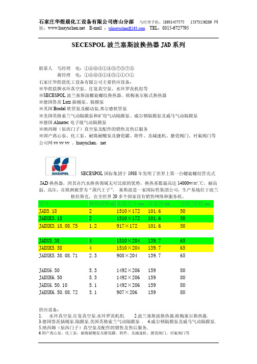
SECESPOL波兰塞斯波换热器JAD系列
石家庄华煜晨化工设备有限公司主要供应设备:
※华煜晨牌水环真空泵、往复真空泵、水环罗茨机组等
※SECESPOL波兰塞斯波螺旋螺纹换热器。
欧梅塞尔板式换热器
※德国鲁茨Lutz插桶泵、隔膜泵
※英国Bredel软管泵及蠕动泵,弗尔德软管泵
※美国英格索兰气动隔膜泵和矿用气动隔膜泵、威尔顿隔膜泵及威马气动隔膜泵
※德国Almatec电子级气动隔膜泵
※纳西姆(原西门子)真空泵及配件的销售及售后服务
※国产离心泵、化工泵、耐腐耐酸泵及搪瓷罐、附件、及减速机、搪瓷阀门、衬氟阀门等公司网vv vv vv 。
huayuchen。
net
联系马经理电:①⑧⑨③①④⑤⑦⑤⑦⑤
蒋经理电:①⑧⑨③①④⑤①①〇①
公司电:〇③①⑤-⑥⑦②⑦⑦⑨⑤
SECESPOL国际集团于1988年发明了世界上第一台螺旋螺纹管壳式
JAD换热器,因其在汽水换热领域无可比拟的优势,换热系数最高达14000w/㎡.℃,耐高温、高压,在欧洲被誉为“蒸汽王子”。
塞斯波是一家国际性集团公司,生产基地位于波兰格坦斯克,在全世界20多个国家设有销售网络和服务机。
JADX6.50 5.3 1492×206 159 80
JADXK6.50 5.3 1492×206 159 80
JADX6.50.10 5.1 1492×206 159 80
JADXK6.50.08.72 3.1 907×206 159 80
JADX9.88 10.7 1481×253 219.1 100
JADXK9.88 10.7 1481×253 219.1 100
JADX9.88.10 8.3 1481×253 219.1 100
JADXK9.88.08.65 4.9 886×253 219.1 100
JADXK9.88.08.85 6.2 1086×253 219.1 100
JADX12.114 18.4 1681×340 273 125
JADXK12.114 18.4 1681×340 273 125
JADX12.114.10 14.9 1681×340 273 125
JADXK12.114.08.50 6.3 781×340 273 125
JADXK12.114.08.60 6.5 881×340 273 125
JADXK12.114.08.75 8.8 1031×340 273 125
JADX17.217 46.5 2364×670 508 150
JAD26.480 77.4 3120×819 510 200
产品详细介绍
JAD螺旋螺纹管换热器是SECESPOL国际集团的主导产品,体积只有传统管壳式换热器的十分之一,采用全不锈钢焊接结构,既具有钎焊板式换热器体积小、耐高温的优势,又克服了密封垫板式换热器胶条(材质主要是丁.腈橡胶和乙丙橡胶)老化、维修费用高的缺陷。
性能特点:
非对称设计理念
结构紧凑、占地面积小
全不锈钢焊接,耐高温、高压
汽水换热中,换热系数可达14000W/㎡.℃
螺旋螺纹管反向缠绕,湍流效果好
体积小、重量轻,安装方便
清洗方便、费用低,设计寿命长达40年
设计灵活,应用条件广泛
塞斯波换热器性能特点:
高效换热、节能环保;全不锈钢焊接,耐高温、高压;结构紧凑、占地面积小;
体积小、重量轻、安装方便;清洗方便、费用低,设计寿命长达40年;
设计灵活,应用条件广泛。
塞斯波换热器规格齐全,系列完整,结构紧凑,体积小,可以降低基建投资,减少安装费用,
减小占地面积,广泛应用于:化工、热电、纸浆造纸、造船、制药、啤酒饮料、汽车、食品、机械加工、电力、纺织、暖通空调等行业。
非对称设计理念,结构紧凑、占地面积小,全不锈钢焊接,耐高温、高压,汽水换热中,换热系数可达14000w/m2.℃,螺旋螺纹管反向缠绕,湍流效果好,体积小、重量轻,安装方便,清洗方便、费用低,设计寿命长达40年,设计灵活,应用条件广泛先进的工艺传统的管壳式换热器体积庞大,结构简单,换热系数低。
JAD换热器只有其体积的十分之一左右,却能达到同样的换热效果、
原因在哪儿呢?因为JAD换热器将换热管设计成了螺旋螺纹管反向缠绕结构,这种特殊结构极大得改变了流体流动状态,形成强烈的湍流效果,提高了换热系数,减小了传热面积。
设计机理目前国市场上大部分的换热工况为非对称流换热,即两种流体流经换热器的流量不同,这就需要有两个不同的换热面积。
而板式换热器的设计机理就是对称流传热,无法为流体提供大小不一的换热面积。
JAD换热器设计时就针对市场上这种非对称流换热,特意使两侧的换热面积不相同,以满足复杂的工况要求。
壳容积最大能达到管容积的4.2倍。
传热原理:在JAD换热器的设计和应用中,增大流速可以增加传热膜系数,从而提高总传热系数,使换热器的结构紧凑,湍流状态更强烈。
JAD独特的设计以最少的材料达到最佳的换热效果,同时考虑压降和换热系数的最佳组合关系,以最小的压降达到最好的换热效果,让您使用时付出更少,获益更多。
独特的100°连接采用100°连接,可以使换热器全部参与换热,不留死角;使流体自动冲刷管路,降低堵塞倾向;对流体起到缓冲作用,降低噪音。
材质:
管:不锈钢, 壳:不锈钢, 焊接: 不锈钢, 法兰: 不锈钢或碳钢。
应用范围:
JAD换热器结构紧凑,体积小,可以降低基建投资,减少安装费用,减小占地面积,广泛地应用于:。