JEM-2100透射电镜JSM-7600F场发射扫描电镜开放使用及
- 格式:doc
- 大小:34.50 KB
- 文档页数:2


2100F高分辨电镜操作顺序--个人小结编辑整理:尊敬的读者朋友们:这里是精品文档编辑中心,本文档内容是由我和我的同事精心编辑整理后发布的,发布之前我们对文中内容进行仔细校对,但是难免会有疏漏的地方,但是任然希望(2100F高分辨电镜操作顺序--个人小结)的内容能够给您的工作和学习带来便利。
同时也真诚的希望收到您的建议和反馈,这将是我们进步的源泉,前进的动力。
本文可编辑可修改,如果觉得对您有帮助请收藏以便随时查阅,最后祝您生活愉快业绩进步,以下为2100F高分辨电镜操作顺序--个人小结的全部内容。
装好试样后,开始操作JEM—2100F的步骤:1、打开beam阀,在LOW MAG下,找到薄区所在的位置;2、在LOW MAG下将放大倍数调至500倍,然后切换至MAG1;3、找到一个薄区,将放大倍数调至2000倍,按下STD FOCUS,再进行调Z的步骤:1)方法一:将试样边沿移至屏幕中心,按下IMAGE WOBB X,试样呈抖动状态,再通过调节,使屏幕中心试样不在抖动为止;2)、方法二:找到试样薄区,逆时针旋转BRIGHTNESS,使电子束汇聚为一点,再通过调节,使各衍射斑点汇聚于同一点;4、将放大倍数调至100K倍(调节放大倍数时,需要同时旋转BRIGHTNESS和MAG/CAM L),并将无试样区域移至屏幕中心,逆时针旋转BRIGHTNESS至电子束呈合适大小内、外圆形;5、按下BRIGHT TILT按钮,并通过调节SHIFT X和SHIFT Y将电子束移至屏幕中心,再通过调节DEF/STIG X和DEF/STIG Y将电子束的内圆恰好移至外圆的中心(若电压对中过程中,平移与偏转相互影响,则联动比有问题,需要调最新的合轴文件);6、再按下COND STIG按钮,通过调节DEF/STIG X和DEF/STIG Y将电子束的内圆内的图形调成“奔驰”车标形状;7、逆时针旋转BRIGHTNESS,使电子束的内圆和外圆重合,再在HIGH VOLTAGE CONTROL 界面中点击“ON”,按下F4,通过调节DEF/STIG X和DEF/STIG Y使内外圆同心缩放;8、检查电压对中和聚光镜消象散;9、顺时针旋转BRIGHTNESS,使电子束充满整个屏幕,套取一号聚光镜光阑,将电子束调至屏幕中心(机械对中);10、再次合轴,将放大倍数调节至400K倍,再次检查电压对中和聚光镜消象散;11、将放大倍数调至100K倍,并将薄区边沿移至屏幕中心,通过调节OBJ FOCUS旋钮,将试样边沿调至为微欠焦(略显白色边沿),再将放大倍数调至400K倍,并将边沿区移至屏幕中心,按下F1,然后打开CCD,并调出傅里叶变换,按下OBJ STIG,通过调节DEF/STIG X和DEF/STIG Y和OBJ FOCUS旋钮(使傅里叶变换为一圆环),得到清晰的高分辨像;12,关闭CCD,再按下F1,将放大倍数调至100K倍,找到感兴趣薄区,并将电子束汇聚于一点,按下SA DIFF按钮,并将相机常数调至60CM,手动将菊池线的交点移至电子束中心;至此,已完成电镜合轴、消象散、踩带轴的步骤,接下来便可进行选区电子衍射、明场像、暗场像和高分辨像的操作.一、选区电子衍射步骤:1、合轴完成后,在TEM、MAG1模式下,将感兴趣区移至屏幕中心;2、通过感兴趣大、小来套取合适的选区光阑;3、按下SA DIFF按钮转为衍射模式,获得相应的电子衍射花样,并通过调节MAG/CAM L 获得合适的相机常数(20-30CM)-—-不同相机常数的意义;4、通过顺时针旋转BRIGHTNESS和调节DIF FOCUS获得足够暗、圆锐的衍射斑点。

JEM-2100透射电子显微镜操作流程⏹冷阱、高压以及LENSE分两次加液氮,分两步升高压总计1h开LENSE,聚光镜光阑1档⏹安放样品使用样品杆前,请仔细检查样品杆是否完好、是否需要维护:销钉是否松动、高度感应端是否脱落)载物铜网正面朝上,压片压好载物铜网后轻轻旋紧螺钉洗耳球吹气确保样品杆关键部位没有杂物用样品杆中部轻击左手手掌,确保压片压好载物铜网⏹装样品杆预抽过程销钉对准卡槽,水平垂直推入样品杆(不得旋转),开泵预抽(PUMP),听到噗的声音后松手,等样品杆旁边绿灯变亮后开始进杆;进杆紧握样品杆把手分两次向里均匀旋进(顺时针),直至样品杆进入样品室(该过程不得松手并有向外拉力、不得产生轴向力)拔杆确保关闭灯丝与CCD的前提下,用均匀的外力将样品杆向外拔(该过程较长),当样品杆受到阻力时,即可向外旋转(逆时针),旋转受到助力时,停止旋转,再用均匀力向外拔(该过程较短),当样品杆再次受到阻力时,即可向外旋转(逆时针),听到气门“噗”的声音时,停止拔杆。
手挡住样品杆尾部,放气(AIR)直至气门再次发出“噗”的声音时,将样品杆拔出样品室外。
测试步骤电压中心STD FOCUS低倍找样LOW MAG SPOTSIZE 1高倍照相MAG 1双中心调节聚光(BRIGHTNESS)看光斑是否在中心,不在中心采用电子束(SHIFT X Y)平移至中心粗聚焦利用IMAGE WOBB X Y、Z ⇑,Z ⇓调至样品不动为止1—5合轴在双中心的基础上(30 K),SPOTSIZE 5 光斑不在中心,采用电子束(SHIFT X Y)平移到中心,SPOTSIZE 1光斑不在中心,采用电子枪(F4+SHIFT X Y)平移到中心,调完点去F4,继调SPOTSIZE 1,反复多次,直至光斑中心不因SPOTSIZE的变化而偏移荧光屏中心注意:SPOTSIZE 5时不得采用F4键盘调像散100 K 将样品移开,用红线框选住碳膜,配合OBJ FOCUS 的FINE 或COARSE调出傅里叶椭球后,采用OBJ STIG+STIG X Y将椭球调节为圆形120 K 将样品移开,用红线框选住碳膜,先采用OBJ STIG+NTRL调出傅里叶椭球,再配合OBJ FOCUS 的FINE 或COARSE,采用OBJ STIG+STIG X Y将椭球调节为圆形。

JEM-2100F场发射透射电镜用双倾样品台非公开招标意见公示
粉末冶金研究院“JEM-2100F场发射透射电镜用双倾样品台”项目采用拟采用非公开招
标方式进行,该项目拟从捷欧迪拓姆(上海)贸易有限公司购买。
现将有关情况向潜在供应
商征求意见。
征求意见期限从2015年9月16日起至2015年9月23日止。
潜在供应商对公示内容有异议的,请于公示期满后两个工作日内以实名书面(包括联系人、地址、联系电话)形式将意见反馈至中南大学资产与实验室管理处(联系电话:88836825 联系人:肖老师)。
附:专家论证意见及专家姓名、工作单位、职称。
申请单位理由:
粉冶院的JEM-2100F场发射透射电镜配件双倾样品台、机械泵已使用7年,出现老化和
故障现象,已维修过多次,目前需要更换。
因双倾样品台、机械泵零部件是透射电镜不可缺
少的重要配件,而其他公司生产的零部件与JEM-2100F透射电镜均不兼容,只能向捷欧迪拓
姆贸易有限公司(日本电子在中国的代理公司)购买,故申请非公开招标采购。
2015年9月16日
JEM-2100F场发射透射电镜用双倾样品台
非公开招标采购专家论证意见表
2015年9月16日。

JEM-2100f透射电镜测角台的维护与故障处理刘小青;邓志刚;罗婷婷;谢峻林【摘要】简述了JEM -2100f透射电镜测角台结构及样品杆进样、取样工作原理,分析了引起测角台故障的原因,阐述了测角台故障处理方法及日常维护技巧。
%In this paper ,the goniometer structure and working principle ofinserting/removing speci‐men holder of JEM‐2100f transmission electron microscope were briefly introduced ,the goniometer failure causes were analyzed ,the fault handling methods and daily maintenance skills of goniometer were described.【期刊名称】《分析仪器》【年(卷),期】2015(000)002【总页数】3页(P96-98)【关键词】透射电镜;测角台;维护;故障处理【作者】刘小青;邓志刚;罗婷婷;谢峻林【作者单位】武汉理工大学材料研究与测试中心,武汉 430070;武汉理工大学材料研究与测试中心,武汉 430070;武汉理工大学材料研究与测试中心,武汉430070;武汉理工大学材料研究与测试中心,武汉 430070【正文语种】中文JEM-2100f透射电镜测角台(以下简称测角台)是透射电镜成像系统的重要组成部分,是JEM-2100f透射电镜能够在纳米及原子尺度进行物质微观形貌观测和晶体结构研究的关键部件之一。
测角台一旦出现故障势必导致透射电镜无法正常工作,熟悉测角台结构及其工作原理,掌握测角台的维护与故障处理技巧由此显得非常重要。
透射电镜维护与故障处理专业性很强 [1-8]。
对测角台而言,如果不是机器老化或测角台本身质量问题,测角台故障主要与样品杆前处理不够,以及进样、取样操作不当有关。
JEM-2100F/2200FS操作说明制作:北京东方捷欧技术服务站马宁一,开机(此步只能由实验室管理员操作)。
1. 合上配电柜中电镜主机的单相电源,同时合上循环水的三相电源。
2. 合上主机的稳压电源开关。
3. 合上主机电源柜上的电源开关。
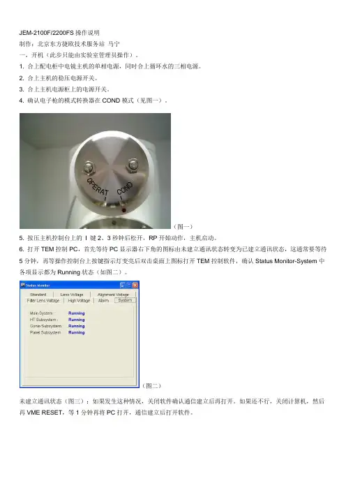
4. 确认电子枪的模式转换器在COND模式(见图一)。
(图一)5. 按压主机控制台上的I 键2、3秒钟后松开,RP开始动作,主机启动。
6. 打开TEM控制PC,首先等待PC显示器右下角的图标由未建立通讯状态转变为已建立通讯状态,这通常要等待5分钟,再等操作控制台上按键指示灯变亮后双击桌面上图标打开TEM控制软件,确认Status Monitor-System中各项显示都为Running状态(如图二)。
(图二)未建立通讯状态(图三):如果发生这种情况,关闭软件确认通信建立后再打开。
如果还不行,关闭计算机,然后再VME RESET,等1分钟再将PC打开,通信建立后打开软件。
(图三)7. 确认电源柜上的60L,20LSIP真空档位选择器在X10-6Pa的位置,并且指针基本上是在左端基本到底的位置,如指针指示超过0.5X10⁻⁶Pa,请立即通知服务中心。
(图四)8. 确认真空符合要求后加高压(在COND模式,从100KV起加,参照长假期处理)备注:如无法正常开机,请检查下列各项:1,检查电源,包括电源柜中的主闸及电镜分开关是否正常,稳压电源是否在开启状态,以及主机电源柜的空开是否在开启状态。
2,打开Status Monitor-Alarm,察看是否有变红的报警提示(一般会自动弹出此报警窗口,如图五),如有请与服务中心联系。
(图五)3,打开TEMCON软件后弹出下列窗口(图六)是由于过早打开软件造成,关闭软件后再次开启此问题就会解决(图六)二,插拔样品杆1,放入样品杆前,如当时EMSN 是ON 的状态不要关掉灯丝(热场的灯丝一般总保持在发射状态,所以无须关灯丝,这是与普通电镜的区别之处),同时更换不同的样品杆要在计算机里选择相应的型号。
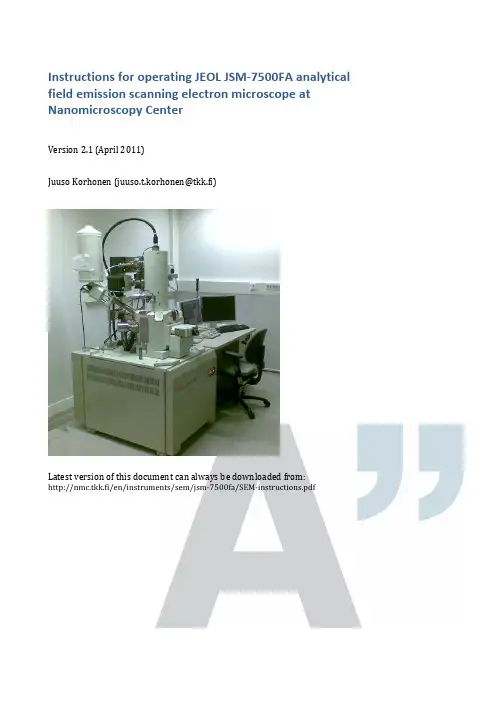
Instructions f or o perating J EOL J SM-‐7500FA a nalytical field e mission s canning e lectron m icroscope a t Nanomicroscopy C enterVersion 2.1 (April 2011)Juuso K orhonen (***********************)Latest v ersion o f t his d ocument c an a lways b e d ownloaded f rom:k.fi/en/instruments/sem/jsm-‐7500fa/SEM-‐instructions.pdfOfficial i nformationNew u ser t rainingInexperienced u sers h ave a c ouple o f o ptions, l isted b elow i n t he o rder o f preference.1.Ask f or t raining f rom t he m ost e xperienced S EM u ser o f y ourresearch g roup.2.Attend t o t he c ourses T fy-‐125.4313 a nd T fy-‐125.4314 M icroscopyof n anomaterials (5+5 c r). T hey a re l ectured e ach s pring b y P rof.Janne R uokolainen.3.Ask o ne o f t he a dministrators t o a rrange a t raining s ession.a.Small g roups o f 2-‐3 p eople a re p referred f or t he t rainings.Allow s ome t ime t o g ather e nough p eople f or t he g roup.b.Training i s d one u sing a p ractice s ample a nd p ersonalsamples a re u sually n ot i maged.Experienced u sers c an c ontact o ne o f t he a dministrators f or a s hort introduction t o t he e quipment.Every n ew u ser h as t o b e a pproved b y o ne o f t he a dministrators b efore t hey are a llowed t o u se t he S EM o n t heir o wn. T he a dministrator k eeps a s hort (15-‐30 m in) s ession w here t he e ssential s kills o f t he u ser a re c hecked. User a pplicationUser a pplication h as t o b e f illed i n o rder t o g ain r eservation a ccess t o a ny o f the N MC e quipment. T he f orm c an b e f ound f romk.fi/en/documents/nmc_user_application_form.pdf a nd i t i s returned t o o ne o f t he a dministrators f or a pproval.PricingBilling i s d one u sing t he c urrent N MC p rice l ist. C ontact P rof. J anne Ruokolainen f or t he m ost c urrent l ist. P lease n ote t hat i ndividual t raining given b y t he a dministrators w ill a lso b e c harged.Precautions – r ead c arefully•Always c heck t he l iquid n itrogen l evel a nd f ill i f n ecessary.o First u ser o f t he d ay a lways f ills t he t ank.•Keep a ll p arts c lean a nd c lean t hem i f n ecessary w ith e thanol.o Wear g loves w hen h andling h olders.•Fill t he l og b ook o n t he c omputer.o Mark a ny s trange b ehavior o r p roblems t o t he l og b ook.•If s omething i s m issing f rom t he S EM o r f rom t he s ample p reparation room (e.g. g loves, e thanol, h olders, c arbon t ape), p lease i nform o ne o fthe a dministrators (send e mail o r c all).•Use o nly f eatures y ou a re t rained t o u se. F or e xample, d o n ot u se EDS o r R BEI i f y ou d on’t k now h ow t o o perate t hem s afely.•Use o f U SB s ticks i s s trictly p rohibited d ue t o s ecurity i ssues a nd hardware i ncompatibility.•Stay c alm a nd u se y our c ommon s ense.•Contact a dministrators i f y ou a re i n d oubt. C ontact i nformation i s found o n t he l ast p age o f t hese i nstructions.Quick s tartup p rocedure1.Turn o n b oth m onitors a nd c heck t hat S EM s oftware a nd u sage l og(Excel) a re r unning. S tart t hem i f n ecessary. L og i n a s G uest (nopassword).2.Check t he l iquid n itrogen l evel a nd f ill i f n ecessary. T he f irst u serof t he d ay a lways f ills t he t ank.3.Fill t he u sage l og:a.Date, s tart t ime (and e nd t ime).b.Your n ame (and t he n ame o f y our h ost i f y ou d o n ot h avereservation p ermissions).c.Vacuum l evels b efore s tarting.d.Amount o f f illed l iquid n itrogen (write “0” i f y ou o nlychecked t he l evel).e.Write n otes a nd c omments t o t he l ast f ield i s n ecessary.f.Save t he f ile (Ctrl-‐S).4.Prepare y our s ample.5.Insert s ample i nto m icroscope:a.Press E xchange p osition.b.Press a nd h old V ENT f or c a. 1 s ec. O pen s ecuring l atch. W ait.c.Open c hamber a nd i nsert h older a long t he d irection o f t hearrows.d.Close c hamber.e.Press a nd h old E VAC f or c a. 1 s ec. W ait u ntil b linking s tops.f.Operate t he r od t o m ove t he s ample t o t he s tage. I f y ou’re n otabsolutely c ertain h ow t o d o t his, r ead t he d etailedinstructions!g.Take o ut t he r od.6.Wait u ntil v acuum l evel r eaches l ess t han 5⋅10-‐4 P a.7.Set E mission c urrent t o 10 μA.8.Select A cceleration v oltage.9.Press O bservation O N.Shutdown p rocedure1.Press O bservation O FF t o t urn o ff a cceleration v oltage.2.Press E xchange p osition.3.Take o ut h older u sing t he r od.4.Press a nd h old V ENT f or c a. 1 s ec. O pen s ecuring l atch. W ait.5.Open c hamber a nd t ake o ut t he h older.6.Close c hamber.7.Press a nd h old E VAC f or c a. 1 s ec.8.Mark e nding t ime a nd o bservations t o U sage l og a nd s ave f ile (Ctrl-‐S).9.Set S EM M onitor s oftware t o n ormal s ettings:a.Exchange p osition p ressed (green).b.Mode: S EMc.Magnification: m inimum f or b oth S EM a nd L Md.Probe c urrent: 810.Turn o ff s pecial f eatures y ou h ave u sed: I mage r otation, d ynamicfocus, e tc.11.If y ou m ade a ny c hanges i n t he O peration S ettings m enu, c hangethem t o n ormal v alues (scan s peeds, i mage f unction, e tc.).12.Clean t he h olders w ith e thanol i f n ecessary.13.Clean t ables. I f y ou w ant t o s tore y our s amples, m ark t hem w ith y ourname a nd p ut t hem o nto a s helf. T hings l eft o n t he t able a re t hrowninto t he t rash.14.Transfer y our i mages f rom t he s mall c omputer o n t he b ack t able.You c an f ind y our f iles a t t he n etwork d rive c alled H arley.e U SB s tick, S SH, e mail, o r b urn a C D.b.The f iles c annot b e t ransferred d irectly f rom t he S EMcomputer d ue t o s ecurity r easons.15.Turn o ff m onitors. D o n ot l og o ut f rom t he s oftware o r c lose t heExcel l og b ook.Changing s ample1.Press O bservation O FF t o t urn o ff a cceleration v oltage.2.Press E xchange P osition t o m ove t he s tage t o c orrect p osition.3.Take s ample o ut b y o perating t he r od.4.Press a nd h old V ENT f or c a. 1 s ec. t o f lush c hamber a nd o pen l atch.Wait.5.Open c hamber a nd t ake o ut s ample (pull a long t he a rrows, n ot u p).6.Change s ample a nd i nsert h older a long t he a rrows.7.Close c hamber a nd s ecure w ith l atch.8.Press a nd h old E VAC f or c a. 1 s ec. W ait u ntil b linking s tops.9.Insert s ample b y o perating t he r od. T ake o ut r od.10.Wait u ntil c hamber v acuum r eaches 5⋅10-‐4 P a b efore t urning o nacceleration v oltage.Special f eaturesThis i s o nly a q uick r eference. S pecial t raining i s r equired t o u se R BEI o r E DS, because o f s afety i ssues.Infrared c ameraYou c an s ee i nside t he c hamber u sing t he i nfrared c amera.1.Switch c amera o n f rom t he b utton o n t he t able.2.From S EM s oftware s elect N avigator -‐> I nfrared c amera3.Turn c amera o ff w hen u sing R BEI o r E DS.Probe c urrent m eterProbe c urrent m eter c an b e u sed t o c heck t he c urrent g oing t o t he s ample. I t is m ost i mportant i n E DS a nalysis.1.Insert t he d etector b y c hecking P CD f rom t he b ottom r ight c orner o fSEM s oftware.2.Take o ut d etector a fter y ou h ave r ead t he c urrent f rom t he S EMsoftware.Retractable b ackscattering d etector (RBEI)Backscattering d etector i s u sed t o d istinguish b etween e lements o n t he sample.1.Set w orking d istance t o 8 m m o r m ore.a.Inserting R BEI w ith l ess t han 8 m m b etween t he s ample a ndthe o bjective l ens w ill r esult i n s erious d amage.2.Turn o ff i nfrared c amera.3.Insert d etector b y c hecking R BEI f rom t he b ottom r ight c orner o f t heSEM s oftware.4.Select C OMPO o r T OPO f or i mage m ode (same m enu a s S EM a nd L M)and u ser a s low s canning s peed f or o bservation.X-‐ray a nalysis (EDS)This g uide i s n ot a dequate f or p roper o peration o f E DS, b ut i s o nly a q uick reference f or t rained u sers.1.Set w orking d istance t o e xactly 8 m m.a.Focus w ith Z h eight u sing t he r ing o f t he s croll w heel i nsteadof F OCUS.2.Insert R BEI.3.Turn o n b ias v oltage b y c licking t he l ightning i ndicator.a.Wait u ntil c ount r ate s tabilizes.4.Select A nalysis f rom t he r ight s ide o f S EM s oftware.5.Click D T (dead t ime) a nd s elect T4 f rom t he l ist.6.Adjust p robe c urrent s o D T b ecomes g reen (around 20-‐30 %) a ndcount r ate i s c a. 2000-‐3000 c ps.7.Take s pectra, l ine s can, o r m apping u sing t he a ppropriate b uttons.8.When a sked a bout s aving t o a n etwork d rive, s elect O K.9.Save t he a nalysis b efore e xiting a nalysis m ode i n o rder t o b e a ble t oreturn t o t he a nalysis l ater.a.Exporting o nly s aves t he i mage a nd y ou c annot r eturn t omake m ore a nalysis o n t he d ata.10.When y ou a re f inished w ith a nalysis, t urn o ff t he b ias v oltage a ndtake o ut R BEI.Saving E DS s pectraIf y ou w ant t o b e a ble t o p lot y our E DS s pectrum, s elect E xport a nd t hen select M SA f ile. I t w ill s ave t he s pectrum i n a c ompatible f ile f or u se i n O rigin, Excel, o r s ome o ther p lotting p rogram.Detailed i nstructionsOperating t he r od (sample e xchange m echanism)This p rocedure d escribes h ow t o u se t he s ample e xchange m echanism i norder t o e ither r emove o r i nsert a s ample h older i nto/from t he m icroscope.Read t his s ection c ompletely t hrough b efore p roceeding a nd m ake s ure t hatyou u nderstand e very s tep.Precondition: T he e xchange c hamber i s i n v acuum a nd t he d oor s eparatingit f rom t he m icroscope i s o pen. C onfirm t hat E VAC l ight i s l it a nd n otblinking. D epending o n w hether y ou a re i nserting o r t aking o ut a s ample, t heholder m ight b e i n t he e xchange c ompartment (HLDR l ight i s o ff) o r i nsidethe m icroscope (HLDR l ight i s o n).See t he v ideo o n t he c omputer d esktop f or a d emonstration. U PDATE: T hefigures a re f rom a n o ld v ersion o f r od.1.Push t he b ar i nside t he m icroscope b y f ollowing t he p rocedure:a.Lower t he r od t o h orizontal l evel, w hile l ightly h olding i tback.b.Let t he r od b e p ulled i n s lowly.c.Push t he b ar g ently a ll t he w ay i nside u ntil i t s tops (d).•There i s a l ittle r esistance a t t he f inal c ouple o fcentimeters.•The s ample s hould b e n ow e ither r eleased f romthe b ar o r a ttached t o i t (depending o n w hetheryou a re i nserting o r r emoving t he h older).•If y ou h ave n ot p ushed t he s ample a ll t he w ayinside a nd s tart t o p ull b ackwards t here i s adanger t hat t he s ample h older w ill f all t o t hebottom t he s ample c ompartment. I f t his h appens,the w hole s ample c ompartment h as t o b e o pened.Contact S EM a dministrators i n t his c ase.2.Pull t he b ar o ut f rom t he m icroscope u sing t he f ollowingprocedure:a.Pull t he b ar o ut a s f ar a s i t c omes (e).•The t wo a rrows o n t he h older s hould a lign w iththe p ipe e nd.•If y ou h ave n ot p ulled f ar e nough, t he r od m ightbe d amaged d uring t he l ift.b.Lift t he r od u pwards t o v ertical.•Now y ou s hould e ither h ave t he s ample i nside t hemicroscope o r i n t he e xchange c ompartment a ndthe e xchange c ompartment i s i n v acuum.Opening t he s ample e xchange c ompartmentThe f ollowing p rocedure d escribes h ow t o b ring t he e xchangecompartment t o a tmospheric p ressure.Precondition: T here i s n o s ample i nside t he m icroscope o r i t h as b eenbrought t o t he e xchange c ompartment, a nd t he e xchange c ompartment i sin v acuum. F irst c heck t hat H LDR l ight i s o ff o n t he s ample e xchangecompartment (i.e. t here i s n o s ample i nside t he s ample c ompartment).Figure. S ample e xchange r od1.Pressurize t he e xchange c ompartment:a.Press a nd h old (for a bout 1 s econd) t he V ENT b utton o n t heexchange c ompartment.i.The b utton s tarts t o b link a nd y ou h ear s ome s ounds.ii.In a f ew s econds, t he d oor b etween t he e xchangecompartment a nd t he s ample c ompartment c loses.You c an o bserve t his b y e ar a nd b y l ooking a t t hebottom r ight c orner o f t he S EM M onitor.2.Open t he l atch a s s oon a s y ou h ear t he c lick.3.Open t he e xchange c ompartment d oor (it s hould o pen a lmost b yitself).a.You d o n ot n eed t o w ait u ntil t he p umping h as s topped.b.The c ompartment w ill c ontinue p urging f or a f ixed a mount o ftime. Y ou d o n ot h ave t o w ait u ntil i t s tops a nd y ou c anevacuate i t a s s oon a s y ou l ike.4.Now y ou h ave t he s ample c ompartment o pen a nd r eady f orloading/unloading t he s ample h older.Inserting a s amplePrecondition: T here i s n o s ample i nside t he s pecimen c hamber a nd exchange c ompartment i s i n v acuum. F irst c heck t hat H LDR l ight i s o ff o n the e xchange c ompartment (i.e. t here i s n o s ample i nside).1.Move t he s tage t o e xchange p osition:a.Click E xchange P osition o n t he S EM M onitor.i.If b utton i s n ot v isible, c lick "Specimen" f rom t herightmost e dge o f S EM M onitor.ii.Make s ure t hat E XCH P OSN i s l it o n t he e xchangecompartment, b efore p roceeding.2.Bring t he e xchange c ompartment t o a tmospheric p ressure b yfollowing p rocedure i n s ection “Opening t he s ample e xchangecompartment”. Q uick n otes:a.Press a nd h old V ENT f or c a. 1 s ec.b.Open l atch. W ait.c.Open c hamber d oor.3.Put o n g loves i f y ou d o n ot h ave t hem a lready o n.a.Parts t hat a re i n c ontact w ith t he v acuum s hould b e k eptabsolutely c lean. I f y ou h ave t ouched s ome p art, c lean t he p artwith e thanol (not a cetone).4.Insert h older t o t he s pecimen c huck:a.Slide t he s pecimen h older i nto t he s pecimen c huck a long t hearrow d irection o n t he s pecimen h older.5.Check t hat t he O-‐ring s eal o n t he d oor i s O K a nd w ipe i t w ith a c leanglove i f n eeded t o g et r id o f a ny d ust.a.If t he r ing i s r eally d irty, w ipe i t w ith e thanol o r i sopropanol(do n ot u se a cetone o r m ethanol).6.Close t he c hamber d oor a nd s ecure i t w ith t he l atch.7.Evacuate t he c ompartment b y p ressing a nd h olding E VAC (forabout 1 s econd). T he l ight w ill s tart b linking.a.Wait u ntil t he l ight s tops b linking a nd t he d oor s eparatingthe e xchange c ompartment i s c losed. Y ou c an o bserve t hisfrom t he b ottom r ight p art o f t he S EM M onitor.8.Insert t he s ample h older i nside t he m icroscopea.Refer t o s ection “Operating t he r od” i f i n d oubt.9.A p opup w indow s hould a ppear o n t he S EM M onitor. N ow s elect t heappropriate h older a nd s et t he o ffset v alue.a.If p opup d oes n ot a ppear, t ake o ut t he h older a nd i nsert i tagain.10.Wait u ntil t he v acuum l evel r eaches 9.6·10-‐5 P a (if t hat i s n otpossible, w ait a t l east u ntil 5·10-‐4 P a).Taking o ut s amplePrecondition: T here i s a s ample i nside t he m icroscope a nd e xchange compartment i s i n v acuum. F irst c heck t hat H LDR l ight i s o n o n t he s ample exchange c ompartment (i.e. t here i s a s ample i nside) a nd E VAC l ight i s o n and n ot b linking.1.Click O bservation O FF t o t urn o ff a cceleration v oltage.2.Click E xchange P osition t o m ove t he s ample h older t o t he e xchangeposition.a.Make s ure t hat E XCH P OSN i s l it o n t he e xchangecompartment b efore p roceeding.3.Bring t he s ample t o t he e xchange c ompartment b y o perating t herod.a.Refer t o s ection “Operating t he r od” i f y ou a re n ot a bsolutelycertain h ow t o d o t his.4.Pressurize t he e xchange c ompartment:a.Press a nd h old V ENT f or c a. 1 s ec u ntil i t s tarts t o b link.b.Open s ecuring l atch. W ait.c.Open c hamber d oor.5.Now y ou h ave t he s ample c ompartment o pen a nd y ou a re r eady t akeout y our s ample. I f y ou a re d one w ith t he i maging, j ust c lose t heexchange c hamber a nd e vacuate i t o therwise c ontinue w ith i nsertinga n ew s ample. D o n ot l eave t he c hamber o pen f or a l ong p eriod o ftime, b ut e vacuate i t i f n eeded.Sample h oldersSample h olders c onsist o f a b ase p art a nd a n a dapter p art (show o n t he f igure right). T here a re t hree d ifferent a dapters f or d ifferent s pecimen s tubs s hown in t he f igure b elow (a, b , c , d ).The m ost b asic h olders a re t he 12.5 m m (b-‐1) a nd 25 m m (c-‐1) a luminum “JEOL” s tubs . T hey s hould b e u sed w henever p ossible. S tubs s hould a lways b e available a t t he s ample p reparation r oom, b ut y ou c an a lso o rder y our o wn ones e .g. f rom E MS (order n umbers 75730, a nd 75700). T he u se o f r egular holders i s i ncluded i n t he o peration p rice o f t he m icroscope.Also “mini-‐stubs” a re a vailable f or u se w ith a p rovided a dapter. T hey a re preferred f or s mall s amples. T hey c an b e o rdered f rom T ed P ella (order numbers 16180, a nd 16181).For s pecial o ccasions, a H itachi a dapter (a) c an b e u sed. S pecial c are m ust b e taken w hen u sing t hese h olders, b ecause t hey l ack s ome s afety f eatures. Ask a dministrators, i f y ou h ave s pecial r equests f or h olders. T here a re a lso different k inds o f c ross-‐section h olders a vailable. A sk t he a dministrators f or more i nformation.Attaching a dapter t o b ase p arta) Make s ure t hat p arts a re n ot d irty, c lean i f n ecessary. b) Place a dapter o n t he b ase p art.c) Tighten s crew o n t he b ase p art l ightly.Figure. A ttaching a dapter t o base p art.Figure. 12.5 m m a nd 25 m m "JEOL" stubs.Figure. "Mini-‐stubs" a nd 12.5 m m a dapter.Figure. C ross-‐section holders.Sample h eightAlign t he t op o f t he s ample w ith t he g roove i nside t he J EOL a dapter p art. U se the s crew o n b ottom t o r aise o f l ower t he s ample. W hen u sing a nother holder, m ake s ure t hat h eight f rom t able t op l evel i s e xactly 25 m m.CoatingFor n on-‐conductive s amples a c oating i s u sually n eeded f or o bservation i n SEM. T his c an b e e asily p erformed b y u sing s putter c oating o f g old, p latinum, or g old-‐palladium. T here i s a s putter c oater a t N MC, w hich c an b e u sed f or this p urpose. R esolution l imiting f actor i s t he g rain s ize, w hich i s u sually 5-‐20 nm d epending o n t he c onditions o f s puttering.Also c arbon c oating c an b e u sed t o m ake s amples c onductive. I t i s a nappealing m ethod, w hen d oing X -‐ray a nalysis. I t c reates a v ery u niform l ayer without n oticeable grains.Figure. A lign t op o f stub w ith t he g roove on t he s ample holder.Basic m icroscope o perationBasic c onceptsWorking d istance a nd Z v alueWorking d istance (WD) v alue s ets t he e ffective f ocal l ength o f t he o bjective lens.Z h eight v alue s ets t he d istance o f t he (supposed) s urface l evel o f t he s ample from t he o bjective l ens.These t wo v alues a re e qual, w hen t op o f s ample i s a ligned w ith t he t op o f the h older (ie. 25 m m h igh f rom t able l evel, s ee f igure). W D > Z, i f y our sample i s l ower t han t he c orrect l evel a nd v ice v ersa. I f W D < Z y ou n eed t o set t he S ample O ffset v alue a ccordingly.Sample o ffsetThe h eight o f t he t op l evel o f t he s ample m easured f rom t able t op l evel should b e e xactly 25 m m. T he s ample c an b e s et a lso 0-‐4 m m h igher t han t he nominal l evel, b ut t hen t he S ample O ffset v alue h as t o b e s et a fter i nserting sample. I t i s l ocated a t t he b ottom o f t he s ample h older s elect w indow, w hich pops u p a utomatically a fter h older i nsert.Acceleration v oltage, e mission c urrent, p robe c urrent…The f irst t hing t o t hink a bout w hen s tarting i maging i s t he s election o f acceleration v oltage. T he c hoice d epends o n t he t ype o f t he s ample. S ee table b elow f or s ome e xamples.Sample Observation c ondition NotesGold p articles o n conductive s urface 5-‐30 k V, p robe c urrent a t c a. 10, working d istance 1.5-‐8 m mCoated p orous polymer 1-‐5 k V, p robe c urrent 6-‐10, w orking distance 4.5-‐8 m mUncoated p olymer 0.5-‐1 k V, p robe c urrent < 8, g entlebeam m ode, w orking d istance c a. 8mmCoated b iological sample 1-‐5 k V, p robe c urrent c a. 10, w orking distance 4.5-‐25 m m d epending o n feature s izeUncoated p aper 1-‐2 k V, g entle b eam (GB-‐L) m ode,working d istance 4.5 m m, p robecurrent 6-‐10.Coated p aper 5 k V, w orking d istance 4.5-‐25 m m,probe c urrent c a. 10X-‐ray a nalysis o f conductive s ample 15-‐30 k V, w orking d istance e xactly 8mm, h igh p robe c urrentRetractable B EIdetector i nsertedX-‐ray a nalysis o f poorly c onductive sample 5 k V, w orking d istance e xactly 8 m m,probe c urrent a s h igh a s p ossibleRetractable B EIdetector i nsertedThe e mission c urrent i s t he c urrent d rawn f rom t he e mitter. S et i t a lways t o 10 μA. Figure. S ample height s hould b e exactly 25 m m measured f rom t able top l evel.Probe c urrent i s t he c urrent d irected a t t he s ample. H igher v alues g ive better s ignal t o n oise r atio, b ut c ause m ore c harging a rtefacts i n p oorly conducting s amples. V alue o f 8-‐10 i s u sually a g ood c hoice.AligningUsually t he m icroscope i s a ligned w ell e nough f or m icrometer s cale operation. I n t his c ase, o nly f ocusing i s n ecessary. F or h igher m agnification work, t he e lectron b eam n eeds t o b e a ligned a nd a stigmatism o f t he o bjective lens h as t o b e c orrected.FocusThe f irst l evel o f a ligning i s a lways f ocusing. F ocusing i s d one u sing t he FOCUS k nob o n t he o peration c onsole. C lockwise r otation i s u nder f ocus (weaker l ens) a nd c ounterclockwise i s o ver f ocus (stronger l ens).If p ossible s elect s ome f eature, w hich y ou c an u se i n t he m agnification r ange from c a. 1000 t o 20000.Start f rom a l ow m agnification a nd w hen y ou g et g ood e nough i mage m ove on t o h igher m agnification f or f ocusing. I t t he a lignments a re r eally o ff, y ou might n ot g et a c lear i mage a t a ll.Beam a lignBeam a lign i s a lways d one a t p robe c urrent 8. S elect t he c orrect p robe current v alue f rom t he s oftware.Press A LIGN o n o peration c onsole. T he i mage s tarts t o m ove o n t he s creen. Use t he X a nd Y k nobs t o m inimize t he m ovement. P ress A LIGN O FF (STIG) button w hen i mage h as s topped. R epeat f or m agnifications u p t o c a. 20000. Focus t he i mage w henever n ecessary.Astigmatism c orrectionTo c orrect t he o bjective l ens a stigmatism p ress t he S TIG b utton o n t he operation c onsole (it i s u sually a lready s elected a t t his p oint). M ove o n t o a spherical f eature, w hich y ou a re a ble t o o bserve a t m agnification 10000 o r more.Move t he F OCUS k nob s o t hat y ou g o f rom u nderfocus t o o verfocus a nd b ack several t imes. W hen y ou h ave a stigmatism, t he i mage g ets e longated i n diagonal d irections w hen m oving a round t he f ocal p oint. S elect t he f ocal point w here n o e longation o ccurs.Adjust t he X a nd Y k nobs s o t hat y ou g et t he c learest i mage p ossible. F ocus whenever n ecessary.Other c orrectionsThere a re a lso o ther a lignments, s uch a s s ource a lign, c ondenser l ens astigmator, l ow m agnification c enter, a nd s tigmator c enter c orrections. These v alues s hould n ot u sually b e c hanged a nd t heir u se i s n ot d escribed here.Problems a nd t roubleshootingAnswers t o c ommon p roblemsI w ant t o u se U SB s tick t o t ransfer m y f iles!You c an t ransfer y our f iles t o a U SB s tick f rom t he s mall c omputer a t t he b ack wall. Y ou’ll f ind y our f iles u nder t he n etwork d rive H arley.Help! T here i s n o i mage.Follow t he c hecklist t o f ind t he c ause:1.Are y our Z a nd W D v alues t he s ame? I f n ot p ress W D t o s et c orrectdistance.2.What d etector a re y ou u sing? I f W D<8 m m y ou u sually d o n ot g etimage w ith L EI d etector; a nd i f W D>8 m m S EI g ives o nly s tatic n oise.LM m ode s hould w ork f ine i n t his c ase.3.What i s y our p robe c urrent v alue? I f i t i s l ow, t ry i ncreasing i t.4.If n one o f t he a bove i s t rue, t ry r esetting a lignment. G o t o A lignmentpanel a nd c lick R eset A ll.a.In a r eally b ad c ase t he s ource a lignment h as g one b ad.Contact a n a dministrator t o a lign i t.If t here i s n o i mage w hen s tarting o perationFirst, p ress A CB (auto c ontrast & b rightness). I f y ou e ven s ee s ome s tatic noise, y ou o nly n eed t o f ind t he c orrect f ocal p oint. S ee p revious s ection.In c ase y ou h ave c ompletely b lack s creen w hen y ou s tart i maging, f ollow t he list u ntil y ou h ave i mage.1.Restart o f S EM s oftware:a.File-‐>Exit t o g o t o l ogin s creen.b.Close l ogin s creen f rom E xit b utton.c.Wait o ne m inute.d.Start S EM_Monitor s oftware.e.Log i n a s G uest.2.Restart c omputer:a.Close S EM s oftware.b.Save E xcel l og b ook a nd e xit.c.Restart W indows.d.Start S EM s oftware a nd E xcel l og b ook.3.Restart o peration c onsole:a.Read i nstructions b elow.If v acuum b reaks d uring s ample e xchangeVacuum u sually b reaks i f t he l ever i s p ushed o r t wisted d uring t he s ample insertion. T he c omputer w ill r aise a m aintenance w indow s howing e rror messages. T he m icroscope w ill a utomatically s hut d ownsome p arts a nd t he v acuum p umps h ave t o b e r estarted. B ring t he microscope b ack t o i ts n ormal c ondition b efore p roceeding. F or e xample, lift t he r od b ack t o i ts u pright p osition.1.Locate t he t wo V AC S W b uttons b elow t he t able. T here a re a lso M AINSW b uttons, b ut d o n ot t ouch t hem.2.Shut d own v acuum p umps b y p ressing V AC O FF (0=OFF, 1=ON)button. T he p umps s hould n ow s top, i f t hey w ere n ot s hut d ownalready.3.Wait a m oment a nd r estart p umps b y p ushing V AC O N b utton.a.There i s a 20 m in t imer f or s tarting t he p umps s o y ou w illhave t o w ait a t l east 20 m inutes b efore p roceeding.4.After a ll o f t he e rror m essages h ave d isappeared f rom t he d isplay,you c an c ontinue o perating.Turning o ff c omputer1.Log o ut f rom t he S EM s oftware (File-‐>Exit).2.Save t he E xcel l og b ook (File-‐>Save o r C trl-‐S).3.Close t he E xcel l og b ook.4.Select S hutdown f rom S tart m enu.Powering o n c omputer1.Start c omputer f rom t he p ower s witch.2.Log i n a s S EMUser (password: S EMUser).3.Start E xcel l og b ook b y d ouble c licking “SEM U sage L og” o n t he r ightmonitor d esktop.4.Start S EM s oftware b y d ouble c licking S EM_Monitor.5.Log i n a s G uest.Restarting o peration c onsole1.Turn o ff c omputer.2.Press O P S W O FF f rom b elow t he t able.3.Wait c a. 10 s econds.4.Press O P S W O N.5.Turn o f c omputer.6.Wait a c ouple o f m inutes b efore s tarting S EM_Monitor s oftware.。

JEM-2100培训一、开机程序:1.检查各仪表的读数是否正常(一般一个月检查一次)。
a.离子泵(SIP):开灯丝前应保证真空压力小于4*10-5Pa;b.高压箱:未开高压时,高压箱SF6(高压绝缘气体)气压表大于0.01MPa;电子枪SF6气压表0.28-0.32(主机左侧下方圆表),该压力值不能低于0.28,低于该值不能启动,当前指针在0.3左右;c.水阀压力:左侧Lens(0.06MPa),中间DP泵(0.06MPa),右侧Lens units(0.04MPa),d.循环冷却水箱:温度在18(+/-0.5)度;e.空压机在启动状态:压力表位于主机左侧下方(上面方表),当黑色指针大于红色指针表示空压泵启动,红色指针当前位置为0.25左右;空压机一般一个月放一次。
f.主副系统通讯连接:若通信中断,操作面板右侧后方有重启开关。
g.一般情况下,Gun,Column,Specimen和camera的值Ready状态时为<35,但主要看电源柜上离子泵读书,RT值为54。
抽真空方式为:机械泵抽RT室(储气室);DP泵抽照相室和样品室,DP泵抽到一定程度后SIP离子泵启动抽气,此时潘宁规工作显示真空度值。
2.加液氮:在冷阱中加入液氮,第一次加满后盖上盖子5min后液氮会喷出,再加一次。
一天工作中,隔4个小时要加一次(早上9点左右加满,晚上4点多关的话,中间可以不用再加液氮)。
一旦加了液氮,下班时必须烘烤冷阱。
3.升高压(慢点好):a.点HT ON,高压自动升到120KV;b.程序升高压,Target HT 160KV,间隔0.1KV,1sec,约6.7min,点START;c.程序升高压,Target HT 180KV,间隔0.1KV,2sec,约13.4min,点START;d.程序升高压,Target HT 200KV,间隔0.1KV,3sec,约20.1min,点START;4.放样品:样品杆中放入待观察样品,单倾杆是铜网正面向上,双倾杆是铜网反面向上。
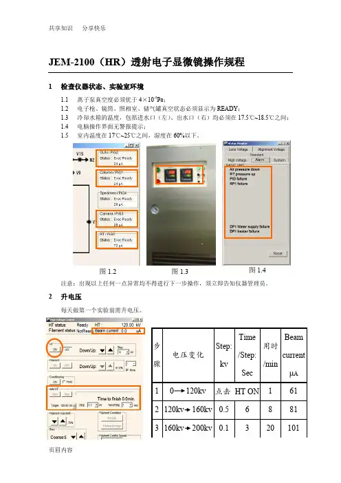
JEM-2100(HR)透射电子显微镜操作规程1检查仪器状态、实验室环境1.1离子泵真空度必须优于4×10⁻⁵Pa;1.2电子枪、镜筒、照相室、储气罐真空状态必须显示为READY;1.3冷却水箱的温度,包括进水口(左)、出水口(右)均必须在17.5℃~18.5℃之间;1.4电脑操作界面无警报提示;1.5室内温度在17℃~25℃之间,湿度在60%以下。
注意:出现以上任何一点异常均不得进行下一步操作,须立即告知仪器管理员。
2升电压每天做第一个实验前需升电压。
图1.2 图1.3 图1.4注意:升电压时必须注意Beam current 的稳定性,当每步完成时的Beam current 超过对应值(即高压箱放电)时,必须等Beam current 自我恢复到对应值并稳定一段时间才能进行下一步操作。
3 加液氮3.1加冷阱液氮每天第一次加冷阱液氮时必须分两次加,先加入少量(1/3瓶热水瓶)预冷,待冷阱温度稳定后再加满,此后每隔3~4个小时加一次液氮(直接加满)。
3.2加能谱仪液氮每隔1天加一次能谱仪液氮,此工作由电镜楼楼管负责,若能谱仪发出缺少液氮的警报声应立即告知楼管或仪器管理员。
注意:加液氮时观察屏的盖子一定要盖上,以防液氮腐蚀铅玻璃;操作面板也盖上塑料薄膜以防止液氮滴溅腐蚀按键。
4 装样、进样注意:任何通过该操作培训、考核的用户未经授权不得对其他用户进行培训,违者重罚。
5 加灯丝(发射电流) 点击Filament ON注意:加灯丝前须确保Beam current 在101μA 左右,离子泵真空度优于2×10⁻⁵Pa 。
冷阱能谱仪液氮罐6观察6.1普通形貌MAG1),6.1.2 放大倍数调至40K6.1.3 , 至图象不晃动;法二:6.1.4 聚焦(OBJ FOCUS6.1.5 ,聚焦后冻结后打开)6.1.6 保存图像6.2高分辨像6.2.1 检查电压中心:将放大倍数调至400K,光斑散开,按HT WOBB检查电压中心是否对中(图像有无左右上下晃动,有晃动则电压中心没有对中)。
JEM2100透射电镜照相系统故障分析
赵梅;王国红;常雷;金头男
【期刊名称】《理化检验-物理分册》
【年(卷),期】2010(046)011
【摘要】对JEM 2100透射电镜照相系统正常拍片程序进行了介绍,分析了卡片、传送机构不工作和传送中途失败等故障及其排除办法,可作为同类型电镜的照相系统故障维修时的参考.
【总页数】3页(P710-711,722)
【作者】赵梅;王国红;常雷;金头男
【作者单位】北京工业大学材料科学与工程学院,北京100022;北京工业大学材料科学与工程学院,北京100022;北京工业大学材料科学与工程学院,北京100022;北京工业大学材料科学与工程学院,北京100022
【正文语种】中文
【中图分类】TG115.21+5.3
【相关文献】
1.日立H-300型透射电镜照相系统故障维修 [J], 廖秉良;时玳
2.TECNAI 10透射电镜真空系统的故障分析和检修 [J], 可金星;黄文琪
3.JEM-1200EX透射电镜照相系统故障分析 [J], 潘力;崔新明;孙庆;栗振宝
4.H-600A型透射电镜真空系统的故障分析及检修 [J], 边晓燕
5.TDX-200透射电镜照相快门的设计原理研究 [J], 杨彦杰;董全林;崔永俊;李鹏
因版权原因,仅展示原文概要,查看原文内容请购买。
JEM-2100F场发射枪透射电子显微镜操作规程1 透射电镜试验主要程序1.1 检查电镜冷却水箱、压缩机及真空系统是否工作正常。
1.2 开电镜主机电源,开电镜控制计算机,并登陆。
待通讯正常后,启动TEM CON控制程序。
1.3 控制程序启动后,系统自动启动抽真空动作。
1.4 待“HT status”显示“ready”后,将电子枪转换为“COND”模式,点击“Auto Procedure”的“start”。
1.5 待47分钟后,“HT conditioning”结束。
再等待0.5~1小时,点击“StartUp”,系统自动升高压、发射电流,直至200kV。
1.6 装入样品。
确认先将测角台归零,再将样品杆装入测角台。
并向冷阱填加液氮。
1.7 待“Beam Valve”激活后,点击“Open”,打开V1、V2阀。
开始实验。
1.8 按使用要求分别进行对中,消聚光镜像散。
1.9 低倍观察样品,寻找所要观察的合适位置,高倍聚焦消像散。
1.10 配合相应附件(STEM-HAADF、BF/DF、EDS)进行观察、记录。
1.11 工作结束时,点击“Beam Valve”的“close”关闭V1、V2阀。
1.12 点击“Stand By”,系统自动将电压降至160kV,使灯丝进入待机状态。
或者点击“AutoHT & Emission”中的“Turn Off”彻底关闭灯丝。
1.13 确认将测角台归零,取出样品台。
1.14 将液氮加热器装入冷阱,点击“Maintenance”下的“ACD & Bake”。
在“ACD & Bake”中将“ACD Heat”设为“on”。
2 基本操作程序2.1 开机/关机2.1.1 开机2.1.1.1 准备。
启动循环水冷机室内外机的电源,启动空气压缩机电源,接通氮气。
电子枪SF6气体压应0.30~0.32 MPa,高压发生器SF6气体压力应0.10~0.12MPa,压缩空气压力应达0.5MPa。
扫描电镜SEM-JEOL7600F详细操作步骤Operating procedure for JEOL 7600F High Resolution Analytical SEMI. Specimen preparationThere are several holders for different kinds of specimens and applications. During your initial training you should have received a general overview of these holders. Also, you should have received training on specimen mounting using the holder that best suits your specific application. Only use a holder for which you have received training by the tool instructor. If you wish to use a different holder, first contact the tool instructor.It is very important to know the kind of holder you are using and the way to mount specimens. For example, for the 12.5 and 26 mm holders, the correct way to mount your specimen is to flush its surface with the cylinder top face (see Fig. 1).FIG. 1. Specimen positioning on 12.5 and 26 mm holders. (Diagram taken from JEOL’s manual.)If your specimen needs to protrude above the cylinder’s top face (or the top face of another holder), you can still use this holder, but you need to estimate (with approx. 1 mm accuracy) the offset between the specimen and holder top surfaces. To make sure you are doing things correctly, use the sample height tool(see Fig. 2). Try to have the sample’s surface aligned with the zero offset line. If it needs to be above this line, read the offset in the meter scale. This offset value will be used when loading your sample in the SEM chamber.FIG. 2. Sample height tool. The right image shows a sample correctly flushed at the zero offset line.II. Loading a specimen1) Log on your session in the Facility Online Manager (FOM) software (icon on the desktop ofthe DATA computer). After a correct login, the SEM monitor should automatically turn on.If it does not, STOP YOUR WORK AND CONTACT A STAFF MEMBER. Never modify any physical connections or push any system buttons. Doing so is unsafe for you and the instrument.2) Confirm that the stage is in the exchange position by checking that the EXCH POSN light onthe airlock is ON. If not:a.Click the OFF button under Observation in the upper left section of the main window(see Fig. 3). The system diagram, located in the lower right corner of the main window, should show the beam stopped at the upper section of the SEM column. This means that the SEM column gate is closed, if not, please contact the tool instructor.b.Click the Observation button in the upper right section of the main window.c.Click the Exchange Position button in the SEM Monitor window.FIG. 3. Main window of Graphical User Interface (GUI).3) Before continuing with the next step, make sure that all the stage coordinates (X, Y, R and T)are “0.0”, except for Z, which should be “38.0”.4) Turn on a “live” image of the chamber using the infrared (IR) camera. To do this, click onthe “Windows” key in the SEM computer keyboard and select “IR Camera” icon.5) Ordinarily, the airlock chamber is under high vacuum and the airlock chamber isolation valveis open. Before loading, the lights in the airlock buttons should be: VENT-off / EVAC-on / EXCH POSN-on / HLDR-off.6) Press the VENT button for 2 seconds then release it. (The VENT light blinks; the isolationvalve closes; N2 gas vents into the airlock.)7) When the VENT light stops blinking, unlock the airlock chamber by releasing the clasp.Open the airlock door.8) Lock the specimen holder into the clamp on the end of the exchange rod. (The specimenheight above the top of the holder is limited to ~5 mm.) Make sure the flat side of the specimen holder lies perpendicular to the insertion direction (see figs. 4 and 5).FIG. 4. Locking the sample holder in place in the airlock chamber. a) Top view of specimen holder. b) and c) Identification of “flat side” with respect to dovetail channel at the base of holder. The flat side is perpendicular to the length of the dovetail channel. d) Correct way of locking specimen holder with the holder’s flat side perpendicular to the insertion direction. (Diagrams taken from JEOL’s manual.)FIG. 5. Sample locked in place in the airlock chamberIT IS VERY IMPORTANT TO CHECK THAT THERE ARE NO VERTICAL GAPS BETWEEN THE HOLDER AND THE CLIP MECHANISM. GENTLY PUSH DOWN ON THE HOLDER TO MAKE SURE IT SITS PROPERLY OVER THE CLIP.9) Before closing the airlock chamber, check that the door’s O-ring is free of dust and dirt andcorrectly positioned in the groove.10) Close and lock the airlock chamber and press the EVAC button. (The EVAC light blinks; theairlock is pumped to high vacuum; the isolation valve opens.)11) Wait until the EVAC light stops blinking. Now the lights in the airlock buttons should be:VENT-off /EVAC-on /EXCH POSN-on /HLDR-off. Also confirm that the system diagram (lower right of main window) indicates that the airlock chamber is under vacuum (gray color)and that the airlock isolation valve is open.12) Lower the specimen-exchange rod horizontally without pulling along its axis (see Fig. 6).Once it is completely horizontal, the low pressure in the chamber may suck the rod in. This is normal, it will stop by itself due to friction.FIG. 6. Lowering of specimen-exchange rod. (a) Initial vertical position. (b) Detail of location of the plastic stopper.(c) Lowering of rod without pulling along its axis. (d) Fully horizontal position. Rod is held extended due to friction in sliding metal parts. Note that plastic stopper is pushed down when rod is horizontal as shown in (e).13) Fully insert the specimen-exchange rod, keeping the holder horizontal, until you feel it cometo a firm stop. Look at the chamber live image to detect this event. Then apply more force to lock the holder in the SEM stage (see Fig. 7).FIG. 7. Lo cking holder in SEM stage. (a) Insertion of rod by pushing horizontally along rod’s axis. (b) Rod position when it first touches the SEM stage. (c) Rod position with holder locked in SEM stage.14) After confirming that the HLDR light has lit up, fully retract the exchange rod horizontallyuntil the plastic stopper snaps and comes up (see Fig. 8). Let the rod sit on the stopper and then tilt up the exchange rod without pulling along its axis. Now the lights in the airlock buttons should be: VENT-off / EVAC-on / EXCH POSN-on / HLDR-on.FIG. 8. Retracting exchange rod. (a) Fully retracted and resting on the plastic stopper. (b) Detail of rod resting on plastic stopper. C) Lifting of rod to its vertical position without using any force along rod’s axis.15) Click on the Specimen Offset button in the graphical user interface (GUI) and select fromthe list the holder you installed. If your sample has an offset (in mm) measured with the sample height tool (see Fig. 2), enter it in the specimen surface offset field of the specimen holder pop-up window (see Fig. 9).FIG. 9. Graphic user interface showing the specimen holder popup window.III. Obtaining an image1) Wait until the chamber vacuum is at 5x10⁻⁴ Pa or lower. Open the Gun Isolation Valve byclicking the ON button under Observation.3) Select the SEI detector and SEM mode, and click on the working distance (WD) in the imageinfo area of the GUI (see Fig. 10). VERY IMPORTANT: Only click on WD when in SEM (high mag mode), never do it in LM (low mag mode). Select 15 mm from the list and click “OK” in the window that pops up after clicking WD. This action will focus the beam toa WD of 15 mm and will bring the stage to Z=15.0+OFFSET. If the stage doesn’t move,check that the ZFC button is “on” (green). Keep an eye on the movement in the IR camera window.FIG. 10. Graphic user interface showing the position of the WD indicator/selector area.4) Unfreeze the image, if necessary, by clicking on the FREEZE button in the knobset panel(see Fig. 11).FIG. 11. Knobset panel, specimen stage control panel and trackball.5) Find a feature in your sample by moving the stage using the trackball (see Fig. 11). If needed,select LM mode and, once you find the feature of interest, switch back to SEM. Adjustcontrast and brightness using the autocontrast (ACB) button or the IMAGE CONTRAST and BRIGHTNESS knobs in the knobset panel (see Fig. 11). If the offset is correct, the image should be rather focused. Now, rotate the outer ring of the trackball until the image is in good focus. As you rotate the ring, the Z value changes. Make sure Z doesn’t change by more than ±2 mm from its initial value. If not sure about this step, please contact the tool instructor.6) Once the image is in focus, update the sample offset. For example, if your sample had aninitial offset of 3 mm (Z=15.0+3.0=18.0 mm), and after focusing with the outer ring, Z=17.5 mm, then the new offset should be OFFSET=17.5 - 15.0 = 2.5 mm. Click on the sample holder image (see Fig. 9) and enter the new offset in the corresponding field.7) Choose probe current setting. You may change the probe current by selecting the desiredlevel in the probe current section of the GUI (right under the WD info area, see Fig. 10):a.For most secondary electron (SE) imaging choose low current (LC) mode with levels 1-10 (6-7 typical). The objective lens (OL) aperture should be set to #4.b.For analytical work, especially when using wavelength dispersive spectroscopy (WDS),choose high current (HC) mode with levels 11 – 20 and with the OL aperture set to #1.CAUTION.-Do not attempt to change the OL aperture without having been trained on this specific procedure by the tool instructor.CAUTION.-If you change the current setting, repeat steps 5 and 6 to update thesample offset.8) Now, you are ready to navigate to the region of interest in your sample, and if necessary,change the beam parameters and the working distance./doc/46d9e41c941ea76e59fa0401.html e low magnification mode (LM) when necessary by pushing the LOW MAG button inthe knobset panel. Navigate to the area of interest using the trackball./doc/46d9e41c941ea76e59fa0401.html e SEM mode in high magnification when possible. This is selected when the light ofthe LOW MAG button is off.CAUTION.- If you move the stage by more than 1 mm, repeat steps 5 and 6 toupdate the sample offset.c.Set WD to 4-6 mm for best resolution secondary electron (SE) imaging using the inlensdetector (SEI), especially at low beam energies.d.Set WD≤8 mm for good resolution SE imaging using the low, in-the-chamber SEdetector (LEI).e.Set WD=8 mm for EDS, and WD=15 mm for WDS work.CAUTION.- If you desire to change to a shorter WD, repeat steps 5 and 6 to update the sample offset.CAUTION.-Unless you have been authorized by the tool instructor, the minimum WD you can use is 4.5 mm. Note that EDS work is done at WD=8 mm and WDS work is done at WD=15 mm. NOTE.- The shortest WD for 30 keV and 15 keV is 6.5 mm and 4.5 mm, respectively.For beam energies 2 keV, the shortest WD can be 2 mm, however, make sure you have authorization from the tool instructor before setting WDs below 4.5 mm.IV. Optimizing an image1) Align the beam.a.Set magnification to ~10,000x - 50,000x using the MAGNIFICATION knob in theknobset panel.b.Focus the image (FOCUS knob in knobset panel) and correct astigmatism if necessary(see IV.2)c.Turn the wobbler on (WOBB button in knobset panel). If the image shifts, adjust X and Yknobs to stop image shiftingd.Turn the wobbler off.2) Astigmatism correction.a.Find a feature that has approximately circular shape using medium to high magnification./doc/46d9e41c941ea76e59fa0401.html ing the FOCUS knob, check for astigmatism by going through over and under focuswhile looking for directionality of focus in the image (over and under focus directionality will be at right angles to each other).c.Stop focus at center of over and under focus (image may not be sharp but has nodirectionality of focus).d.Adjust the X and Y stigmation knobs (one at a time) and try to obtain an image as sharpas possible.e.Focus the image with the FOCUS knob and, if necessary, repeat steps b-e.f.If required, increase the magnification and repeat steps a-e.V. Unloading a specimen1)Click the OFF button under Observation in main window (see Fig. 12). The systemdiagram, located in the lower right corner of the main window, should show the beamstopped at the upper section of the SEM column.2)Click the Exchange Position button in the SEM Monitor window.FIG. 12. Main window of Graphical User Interface (GUI).4) Before continuing with the next step, make sure that all the stage coordinates (X, Y, R andT) are “0.0”, except for Z, which should be “38.0”.5) Turn on a “live” image of the chamber using the infrared (IR) camera. To do this, click onthe “Windows” key in the SEM computer keyboard and select “IR Camera” icon.6) Ordinarily, the airlock chamber is under high vacuum and the airlock chamber isolation valveis open. Before unloading, the lights in the airlock buttons should be: VENT-off / EVAC-on / EXCH POSN-on / HLDR-on.7) Fully insert the specimen exchange rod until it “grabs” the specimen holder on the SEMstage. You can check this event in the IR camera image. These steps are describe in steps II.12 and II.13. Confirm that the HLDR light remains on8) Fully retract the exchange rod as described in step II.14. Confirm that the HLDR light goesoff.9) Press the VENT button. (The VENT light blinks; the isolation valve closes; N2 gas vents intothe airlock.)10) When the VENT light stops blinking, unlock the airlock chamber by releasing the clasp.Open the airlock door.11) Remove the specimen. Close and lock the airlock chamber and press the EVAC button. (TheEVAC light blinks; the airlock is pumped to high vacuum; the isolation valve opens.) The lights in the airlock buttons should be: VENT-off I EVAC-on I EXCH POSN-on I HLDR-off.12) Close the IR camera window to increase the life of safe the life of the IR lamp.13) Log off your session in the Facility Online Management (FOM) software. The SEM monitorshould automatically turn off. If it does not, please contact the tool instructor.V. Notes on using the TED detector1)Make sure you have previously accurately determined the stage offset (see section III).2)Go to a WD between 6-8 mm.3)Verify that the vacuum level is in the mid 10-4 Pa range or better.4)Click the OFF button under Observation in main window (see Fig. 12). This will isolate thevacuum in the e-beam column.5)Insert the TED and wait until the vacuum level is back at 5x10⁻⁴ Pa or better. This will take afew minutes.6)Once the vacuum level is appropriate, click the ON button under Observation in mainwindow.VI. Policy for mounting powder samples (including magnetic powder samples)We need to be extra careful when mounting powder sample, especially magnetic.1)Before mounting ANY powder sample, YOU NEED TO SHOW IT TO THE TOOLMANGER TO RECEIVE GREEN LIGHT TO GO ON. Once it is determined that it is safe for the system, you can repeat the mounting method as many times as you want on your own.In the next section you can find some tips on mounting powder samples, including magnetic powder samples.2)The closest WD for magnetic powder samples is 8mm. You can't image these samples anycloser.3)Make sure you secure extremely tight any bulk magnetic sample to the sample holder toavoid any chance of having it fly onto the objective lens.VII. Tips for mounting powder samples (including magnetic powder samples)A good general procedure is to cover an aluminum or carbon stub with carbon paint or silver paint/cement and quickly deposit a very small amount of powder on to the stub before the paint dries. Once dry, blow off any loose particles with compressed air. Remember that YOU CAN’T DO THIS IN 1L32, you need to do it in an approved lab here on in your owninstitution.Nano sized magnetic particles .- If the particles are nano sized and are relatively small in number, mounting them on a carbon stub by drying an alcohol suspension is OK. The weak force will keep them stuck to the stub. They can also be mounted on lacey or holey carbon TEM grids the same way (this implies using the TEM sample holder). Mounting on TEM grid reduces considerably the interaction volume allowing higher resolution for elemental mapping.Imaging large size (> 1 µm) magnetic particles.- This size particles cannot be mounted as in the previous bullet, because the objective lens (OL) flux will pull them onto the lens. For imaging these large particles, to study rough particle morphology for example, you need toinsure that they are FIRMLY stuck down in carbon tape with all of the loosely adhering particles blown off with compressed air or nitrogen. (You have to do this in your own lab, or an in approved lab in the CFN, not in 1L32!) For safety of the microscope, only use low mag (LM) mode for imaging these particles. In LM mode, the OL flux field is turned off.EDS of large size magnetic particles.- Mount these particles in a 1” or 1 ” inch standard epoxy mount (see for example, /doc/46d9e41c941ea76e59fa0401.html/material_html/mat1.htm). Polish the mount to expose surfaces of particles and then coat with carbon. This will give the bestmicroanalysis conditions.VERY IMPORTANT! Mounting samples of the kind described in this section CANNOT be done in lab 1L32. Ask the tool manager to give you a holder for you to mount these samples in an appropriate lab in the CFN or in your own institution.。
Ultimate Analytical tool1J S M-7900FSince the development of the first commercial SEM in 1966, JEOL has continued to be atthe forefront of technology innovation and has continually contributed to the advancement ofscience through its SEM technology.The JSM-7900F is a flagship model of a field emission scanning electron microscope (FE-SEM),which aims to facilitate research and technological breakthroughs for future generations. TheJSM-7900F successfully combines ultrahigh-resolution imaging, ultrahigh spatial-resolutionanalysis and higher operability, as well as multi-purpose functions. This new-generation SEMprovides the best data fidelity with the utmost ease of operation.2J S M-7900FUltrahigh spatial resolution ❖ In-lens Schottky Plus FEGThe in-lens Schottky Plus field emissionto the combination of the electron gunelectron gun can be efficiently focused, enabling probe currents on the order of a few pA to several tens of nA even at low accelerating voltages. High-resolution observation is easy, with no need to exchange the objective aperture for tasks from fast elemental mapping to EBSD, CL or WDS analysis.Conventional Schottky FEG Electron gun ❖ Super Hybrid Lens (SHL)The JSM-7900F comes with JEOL’Hybrid Lens (SHL)”. This powerful lens enables observation and analysis of any specimens at ultrahigh spatial-resolution, including magnetic and insulating materials.❖ GBSH-S(GENTLEBEAM Super High resolution)GBSH enhances resolution atvoltages.A newly developed GBSH-Svoltage up to 5 kV to be appliedstage.❖ Detector systemSimultaneous signal acquisitiondetectors is enabled.The JSM-7900F comes with LEDdetector) and UED (upper electronin-lens detector). In addition,(upper secondary electron detector)High spatial resolution observationSpecimen: Nano rod of TiO*Specimen courtesy: Shanghai Jiao Tong UniversityProfessor Shunai CheAcc. Vol.: 0.3 kV (GBSH)Signal: Secondary electronsDetector: UEDMagnification: ×120,000, ×300,000*Reference: S. Liu, L Han, Y. Duan, S. Asahina, O. Terasaki, Y. Cao, B. Liu, L. Ma, J. Zhang, S. Che*, " Synthesis of Chiral TiO Nano fiber with Electron Transition-Based Optical Activity” Nature communications, 3, Article number 1215, 2012Specimen: Ag nanoparticlesSpecimen courtesy: Yamagata University Prof. M. Kurihara and Assistant Prof. T. Togashi Acc. Vol.: 5 kV (GBSH)Signal: Backscattered electronsDetector: RBEDMagnification: ×100,000, ×350,000Oxide nanomaterials Metal nanoparticles10 nm100 nm100 nm10 nm 5J S M-7900F1 μmSpecimen: Cross section of stainless steelinterconnect milled by CPAcc. Vol.: 7 kV (GBSH)Signal: Low angle backscattered electrons Detector: RBEDMagnification: ×120,000, ×200,000Specimen: Solder of Ag, Sn and Cu Acc. Vol.: 5 kV Energy filter: -0.5 kV Signal:High angle backscattered electrons (with UED)Secondary and backscattered electrons (with LED)Detector: UED, LED Magnification: ×7,000Simultaneous signal acquisitionSteel materials1 μm100 nm100 nm Signal differentiation–Applications obtained by a variety of detectors–Compositional and crystalline information Topographic informationMetal materials6J S M -7900FJSM-7900FUltimate Analytical Tool of Next-generationHigh vacuum (10-5 Pa)10 μmThe low vacuum function easily suppresses charging of an insulating specimen.Mg KC K3 μm3 μm3 μmSpecimen: Fractured surfaceof coffee beanAcc. Vol.: 5 kV Vacuum: 150 Pa Magnification: ×500Low vacuum functionLow vacuum (150 Pa)10 μm【EDS analytical conditions】Acc. Vol.: 5 kV, Vacuum: 150 Pa, Magnification: ×900, JED 100 mmEDS detector used7J S M -7900FLow vacuum function–Observation at high magnification–The JSM-7900F provides high spatial resolution even in low vacuum. These images demonstrate that inorganic fillers contained in an organic film on a glass are clearly observed.1 μm1 μmGlass100 nmSpecimen: Fractured surface of organic film on glass Acc. Vol.: 5 kV Vacuum: 150 PaSignal: Backscattered electrons Detector: LVBEDMagnification: ×7,000, ×10,000, ×100,000Magnification: ×7,000Magnification: ×10,000Magnification: ×100,000OrganicfilmGlass8J S M -7900FJSM-7900FUltimate Analytical Tool of Next-generationFilter set: +0.3 kVFilter set: -0.1 kV Filter set: -1 kV 3 μmOperability–Extended automatic functions–Soft materials❖ Neo EngineThe JSM-7900F is equipped with a new electron-optical control system, “Neo Engine/New Electron Optical Engine”, which accumulates JEOL’s superb electron optical technologies. Neo Engine achieves further ease of operations of automatic functions.❖ New platformNew exterior design, with no operation console, dramatically reduces the instrument footprint. Thus, the JSM-7900F accommodates a variety of installation environments.❖ New specimen exchange systemA newly designed specimen exchange system (load lock) is adopted for simple specimen exchange, higher throughput, and higher durability.❖ SMILENAVISMILENAVI is an operation navigation system, which is developed for beginners to grasp basic SEM operations efficiently.Improved operability Specimen: Name card, Acc. Vol.: 15 kV, Detector: UED, Magnification: ×3,500Seamless energy selection using a new energy filterOperability–Extended automatic functions–Specimen: Cross section of mineral (resin-embedded) milled by CP, Acc. Vol.: 5 kV, Detector: RBED, Magnification: ×100,000Automatic functions, with greatly improved precision, allow for beginners to easily acquire a high-magnification image.100 nm100 nmSecondary electronsBackscattered electrons9J S M -7900FOperability–New specimen exchange system–Operability–SEM Supporter for image acquisition support–A new specimen exchange system is adopted. The new system achieves simpler and smoother specimen transfer via guided operations. This capability enables fast specimen exchange for beginners to experts.The SEM Supporter of SYSTEM IN FRONTIER INC. enables automatic line width measurement (metrology) utilizing the contrast of SEM images.【SEM observation】Specimen: Specimen for metrology (MRS5)Acc. Vol.: 10 kVMagnification: ×50,000100 nmSpecimen exchange rodSpecimen exchange chamberOperability– SMILENAVI –SMILENAVIGUI screenSMILENAVI is an assistant tool designed for beginners to allow smooth SEM basic operations. When the operator clicks an icon button according to the SMILENAVI flowchart, the SEM GUI screen is linked to the click operation for guiding the operations.ClickAssistInterlock10J S M -7900FJSM-7900FUltimate Analytical Tool of Next-generationUnit :mm3000 or morePower1000 or more2800 o r m o r e*Specifications subject to change without notice.No. 1301G755C Printed in Japan, Kp。
JEM-2100 操作说明一、合轴操作1.照明系统合轴(1).找亮:当打开灯丝,并且灯丝电流发射之后,应该在荧光屏上找到电子束,若打开灯丝后没有发现电子束,请进行以下操作:将放大倍数降低到10K左右,移动轨迹球,撤除所有光阑,基本上以上操作可以解决大多数没亮的情况若仍然找不到亮,则需调整GUN TILT进行找亮当然,也可以在用户模式下直接对GUN进行清零操作NTRL!正常情况下就能找到电子束了。
(2)灯丝像调节:放大倍数为X40K,将光斑用beam shift移动到屏幕中心,慢慢降低灯丝电流,并且用BRIGHTNESS旋钮将光斑聚到最小,随着灯丝电流下降,可以观察到灯丝像出现。
如图所示标准的六硼化阑灯丝像是均匀对称的四瓣花型的,若发现花瓣不对称,说明灯丝偏了,需要用GUN TILT调节到对称即可。
调节完毕后将灯丝电流升高到正常数值,即稍能看到一点灯丝像阴影。
(3)1、5合轴:将束斑调到SPOTSIZE 5,用beam shift 将束斑移动至屏幕中间,切换至SPOTSIZE 1 ,用gun shift将偏移的束斑移动至屏幕中间,重复此过程直到当切换SPOTSIZE1到5时束斑基本上不发生偏移即可。
(4)聚光镜消象散:观察各个束斑形状,如果发现束斑形状椭圆,则用CONDSTIG 键将束斑调圆即可。
(5)加聚光镜光阑:聚光镜光阑红点位置表示退出,其余的点的大小表示当前所加入的光阑孔大小,顺时针加入光阑至合适的孔径,一般用1号或2号光阑孔,加完后用beam shift 将光斑移动至屏幕中心,这时顺时针转动BRIGHTNESS将光斑放大到与屏幕同大,若光阑没有加正,则光斑不是均匀覆盖屏幕,即光斑补随BRIGHTNESS同心放大,此时调节光阑前端和右侧的两个旋钮使光斑圆心与屏幕同心即可。
(6)样品高度调节:找一处样品,按下IMAGE WOBBLE X或Y,观察图像震动,调节Z键直至将图像震动幅度最小即可2.成像系统合轴(1)电压中心调节:找一样品尖端处,将尖端移动到屏幕中间黑点处。
一、开放大型仪器设备具体参数信息及费用说明大型分析仪器上机预约要求:1、至少提前一天以上申请预约。
2、样品在测试前自行做好前处理,使其符合测试要求。
3、除具体说明外,原则上青年测试基金项目支出费用的样品检测,需项目负责人(或项目负责人指导研究生)经实验仪器中心上机培训认证后,独立上机开展分析测试。
4、预约和上机操作过程中,产生的其他问题与解决办法,以实验仪器中心分析测试中心解释作为依据。
1.透射电子显微镜生产厂家:日本电子(JEOL)规格型号: JEM-2100(UHR)技术参数及指标:分辨率:点分辨率 0.19 nm;线分辨率 0.14 nm加速电压:80, 100, 120, 160, 200 kV放大倍数:50-1,500,000自主上机收费标准:120元/小时,每次预约测试时间不低于1小时,不足1小时按1小时计。
委托测试收费标准:委托测试收费标准150元/小时,如果单个样品测试时间超过20分钟后,每增加20钟,增加50元,不足20分钟按20分钟计。
注意:自主上机需要分析中心负责老师完成进样操作后,方可自行测试。
2.场发射扫描电镜生产厂家:日本电子公司仪器型号:JSM-7800F (配有英国牛津仪器公司X-Max50能谱仪和背散射电子衍射分析仪)仪器性能指标:分辨率:二次电子:0.8nm (15kV), 1.2nm (1kV)加速电压: 0.01 - 30KV 连续可调放大倍数:25X–1,000,000X ;放大倍数连续可调X射线能谱仪(EDS)有效探测面积:50mm2分辨率:优于127eV,(Mn Ka处,计数率为50000cps)分析元素范围:Be(4)--Cf(98)背散射电子衍射分析仪(EBSD)相机分辨率:1344*1024像素角分辨率:<0.1°自主上机收费标准:100元/小时,每次预约测试时间不低于2小时,不足2小时按2小时计。
委托测试收费标准:形貌观察收费标准:50元/个样品(限20分钟),如果单个样品测试时间超过20分钟后,每增加20分钟折算为1个样品数,不足20分钟按20分钟计;能谱分析收费标准:40元/个样品。
JEOL 2100 HRTEM操作规程一开机前准备1. 检查离子泵(SIP)真空<3×10⁻⁵;加速电压120KV在OFF状态;电镜在TEM1-3放大模式;放大倍数<40K;循环水箱、空压机正常工作。
2.给冷阱加满液氮,等喷发一次后盖好冒口。
3.升高压。
点击120KV ON­ →120KV-160KV (3.3min) →160KV-200KV(33.3min)二. 进试样1 装样品:将铜网装入HOLDER(样品杆),用HOLDER后端部位敲击手掌数次,防止铜网或试样掉落。
检查样品杆上的两个O-RING,避免纤维等附着在O-RING。
如有异物,请用洗耳球吹掉或用无毛纸擦净。
装样品时一定要小心!以免损坏样品台或污染镜筒。
2 预抽真空:将HOLDER缓慢插入测角台。
铜销钉进入暗销位置并听到主机“嘀”声后,将开关拨向Pump。
等右手的灯变为绿色,一般再过5-10分钟后,才开始进样。
3进样:顺时针旋转样品杆,当不能继续旋转时(约10度),会感到有一股吸力将样品杆朝镜筒方向吸,顺势让样品杆被吸入至停止(前进距离约3cm)。
然后继续顺时针旋转样品杆至不能旋转,顺势让样品杆被吸入至停止(约15cm)。
此时应检查镜筒的真空,一般应为<2.0&αχυτε;10-5 Pa,如果大于3.5×10⁻⁵则需要停止工作。
让离子泵再抽约10-20分钟,才可加灯丝电流。
三.测试前准备1. 确认离子泵的真空(<2.0&αχυτε;10-5 Pa)2. 确认FILAMENT READY灯亮(在计算机屏幕上)。
3. 按下灯丝加热钮,等电子束发射稳定。
最终的Beam Current 约比不加灯丝电流时多3—5 A。
四.测试操作1. 调入对应电压下的合轴数据(事先管理老师已合好并存储)2. 低倍形貌观察(<100K):在Low Mag下寻找样品位置→回到Mag模式→按下STD Focus →按下Image Wobb X,调整Z轴高度,使图像不再颤抖(正焦)→ 按F1抬起荧光屏→调节Focus使图像清晰(略欠焦)→拍照3. 高倍结构观察(>100K):在低倍合轴完毕的基础上,将放大倍数升到100K以上→按下STD Focus→按下HT Wobb→按亮Bright Tilt →调整DEF X/Y旋钮使该标志物同心放大和收缩→ 按下HT WOBB键使图像停止颤动→按F1抬起荧光屏→调节Focus使图像清晰(如有需要,按下OL Stig,用Live FFT做物镜消像散) →拍照注意:观察过程中一定要顺时针散开光斑,保持亮度value<3000, 否则会烧坏CCD探头!无法维修。
附件:日本电子JEM-2100高分辨透射电镜/ JSM-7600F场发射扫描电镜简介
JEM-2100高分辨透射电镜
一、主要部件
JEM-2100主机,ORIUS SC1000型CCD,牛津80mm2电制冷X射线能谱仪(EDS),双轴倾转样品杆
二、主要指标
电子枪:LaB6(六硼化镧)
点分辨率:0.23 nm
线分辨率:0.14 nm
加速电压:80, 100, 120, 160, 200kV
束斑尺寸: 1.0至25 nm
放大倍数(高倍模式):2000至1,500,000
放大倍数(低倍模式):50至6,000
CCD分辨率:4008×2672 max.
倾斜角:±35º
采用MS Windows为基本操作界面,操作直观简便。
三.特色功能
⏹除高分辨、电子衍射和能谱等基本功能外,该电镜还具备纳米束电子衍射(NBD)、汇聚束电子衍
射(CBD)功能,适用于纳米晶体、多相合金、复合材料的衍射表征。
⏹配备扫描透射电镜(STEM)模式,可采集STEM明场像和暗场像,并配合能谱实现微区元素分析
和元素分布图(Mapping)。
JSM-7600F场发射扫描电镜
一、主要部件
JSM-7600F场发射扫描电镜,牛津80mm2电制冷X射线能谱仪(EDS),背散射探头(BSE)
二、主要指标
电子枪:热场发射
二次电子像分辨率: 1.5 nm(1 kV,GB 模式),1.0 nm(15 kV)
放大倍数:25 至1,000,000×
加速电压:0.1 至30 kV
束流: 1 pA 到200 nA(15 kV时)
数字图像:5120×3840 max.
样品水平行程(X-Y):140 mm×80 mm
倾斜角度:-5 至+70°
旋转角度:360°
工作距离: 1.5 mm 至25 mm
配备上方和低位SEI探测器、BSE探测器
三.特色功能
⏹Gentle Beam模式(即“减速模式”)可将电子束损伤降低到最低程度,适用于不导电样品表征。
⏹配备γ过滤器,能控制能量选择或二次电子及背散射电子像的图像混和率。
⏹背散射探头(BSE)信号可配合二次电子像生成混合运算图像,同时获取形貌图和元素衬度图。
上述特色功能欢迎有需要或有兴趣的课题组联系试用。