轴承安装手册
- 格式:doc
- 大小:2.02 MB
- 文档页数:13

newway气浮轴承使用手册
气浮轴承是一种常见的轴承类型,它通过利用气体压力在轴与轴套之间形成气
膜来实现有效的轴承支撑。
下面是有关newway气浮轴承的使用手册,以帮助用户
正确使用这种轴承。
1. 轴承安装
- 在安装气浮轴承之前,请确保轴与轴套表面干净,并无明显的磕碰或损坏。
- 将气浮轴承轴套插入轴座,确保轴套与轴座之间形成适当的间隙。
- 安装后,应确保轴承处于水平状态,以避免气体泄漏或轴偏移。
2. 气体供应
- 气浮轴承的运行需要稳定的气体供应。
通常使用压缩空气作为供气介质。
- 确保压缩空气干燥、清洁,无油污和杂质。
- 使用适当的压力调节器调整气体供应的压力水平。
根据轴承尺寸和负载要求,选择合适的工作压力范围。
3. 启动和停止
- 在启动轴承之前,确保气体供应已经稳定并达到适当的压力。
- 在轴承运行期间,请注意轴承的工作温度,避免过热。
- 停止轴承之前,应先切断气体供应,确保轴承平稳停止运行后再进行维护或
检查。
4. 维护和保养
- 定期检查气浮轴承的气体供应管路,确保没有气体泄漏或堵塞。
- 清洁轴承表面并检查轴套和轴承是否有磨损或损坏。
- 根据使用情况,定期更换轴承润滑油或脂,在更换前请参阅相关规范和说明书。
通过遵循以上使用手册中提到的准则和建议,您可以确保正确使用newway气浮轴承并延长其使用寿命。
请务必定期进行维护和检查,以确保轴承能够稳定可靠地工作,并避免不必要的损坏和故障。


轴承手册一、轴承的概述轴承是一种能够减小摩擦和支撑轴的旋转装置。
它的主要功能是支撑轴的旋转运动,减小摩擦系数,并传递载荷。
轴承广泛应用于机械设备、汽车工业、航空航天等领域。
轴承的主要类型有滚动轴承、滑动轴承和滚筒轴承。
滚动轴承是利用滚动体在内圈和外圈之间滚动的方式支撑轴,滑动轴承是利用滑动面直接支撑轴的方式,而滚筒轴承则是利用滚筒形状的滚动体来支撑轴。
二、轴承的选型在选择合适的轴承时,需要考虑以下几个方面:1. 轴承的载荷能力根据工作条件确定轴承的载荷类型和大小,包括径向载荷和轴向载荷。
确保轴承能够承受工作条件下的最大载荷。
2. 轴承的转速限制根据工作条件确定轴承的转速限制,以避免轴承在高速转动时产生过热或过大振动等问题。
3. 轴承的尺寸和形状根据轴的直径和轴承座的形状确定轴承的尺寸和形状,确保轴承能够与轴和座配合良好。
4. 轴承的材料和润滑根据工作条件确定轴承的材料和润滑方式,以保证轴承在工作过程中具有良好的耐磨性和润滑性。
5. 其他因素除了上述因素外,还需要考虑工作环境的温度、湿度和清洁度等因素对轴承的影响。
三、常见轴承故障及处理轴承在使用过程中可能出现各种故障,下面列举了几种常见的故障及其处理方法:1. 疲劳寿命故障当轴承在长时间高速运转时,可能会发生疲劳寿命故障。
处理方法包括定期进行润滑和维护保养,及时更换损坏的轴承。
2. 温升过高当轴承在工作中温度升高超过正常范围时,可能会导致润滑剂失效和轴承损坏。
处理方法包括调整润滑剂的种类和用量,改善轴承的散热条件等。
3. 污染和颗粒物侵入轴承周围的污染和颗粒物可能会导致轴承卡死或损坏。
处理方法包括定期清洁和更换密封件,保持轴承周围的清洁。
4. 轴承松动或振动当轴承松动或振动时,可能会导致噪音和轴承损坏。
处理方法包括检查轴承的安装情况,对轴承进行调整和紧固。
四、轴承维护保养正确的维护保养可以延长轴承的使用寿命和减少故障的发生。
下面是一些轴承维护保养的常见方法:1.定期润滑:根据轴承的工作条件,选择合适的润滑剂,并按照规定的时间和用量进行润滑。

skf轴承手册摘要:1.轴承的基本概念与分类2.SKF轴承的特点与优势3.SKF轴承的安装与拆卸4.SKF轴承的保养与维护5.SKF轴承的应用领域正文:SKF轴承手册轴承是机械传动系统中的重要组成部分,它的主要功能是支撑旋转轴,降低摩擦,使机械设备运行更加顺畅。
SKF轴承作为全球知名品牌,一直致力于提供高品质的轴承产品,为各种机械设备的稳定运行提供保障。
1.轴承的基本概念与分类轴承通常分为向心轴承和推力轴承两大类。
向心轴承主要用于承受径向载荷,而推力轴承主要用于承受轴向载荷。
根据轴承的工作原理和结构特点,轴承还可以分为球轴承、滚子轴承等不同类型。
2.SKF轴承的特点与优势SKF轴承具有以下特点和优势:- 高品质的材料和精湛的制造工艺,保证了轴承的强度和耐磨性;- 先进的润滑技术,降低了轴承的摩擦系数,提高了轴承的使用寿命;- 严格的质量控制体系,确保了轴承的精度和可靠性;- 广泛的产品线,满足不同行业和设备的需求。
3.SKF轴承的安装与拆卸轴承的安装应遵循以下步骤:- 检查轴承和轴颈的尺寸、形状和表面质量,确保它们符合安装要求;- 清洗轴承和轴颈,去除污垢和毛刺;- 涂抹适量的润滑剂,降低安装过程中的摩擦;- 按照安装顺序和方向,将轴承安装到轴颈上;- 固定轴承,确保其位置准确;- 检查轴承的旋转是否顺畅,如有异常应立即停机检查。
拆卸轴承时,应按照相反的顺序进行,并注意保护轴承的表面质量和配合尺寸。
4.SKF轴承的保养与维护轴承的保养和维护对保证其正常运行至关重要。
以下是一些建议:- 定期检查轴承的润滑情况,确保润滑剂充足且质量良好;- 定期清洗轴承,清除污垢和磨损颗粒;- 定期检查轴承的运行状态,如发现异常声音、振动或发热等现象,应立即停机检查;- 避免轴承在过载、过热或灰尘多的环境下工作,以免影响其使用寿命。
5.SKF轴承的应用领域SKF轴承广泛应用于各种行业和设备,如汽车、机床、风电、航空航天、工程机械等。
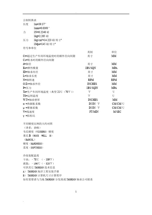
公制转换表长度1m=39.37″1mm=0.0393″力1N=0.2248磅1kg=2.205磅压力1kg/cm²=14.223磅/英寸²1Mpa=145磅/英寸²符号和单位英制单位Ct=超过生产车间环境温度时的额外径向间隙英寸MMCs=吸水时的额外径向间隙d=轴径英寸MMEo=弹性模量1BS/SQN MPAID=轴承内径英寸MML=轴承长度英寸MMN=轴转速RPM RPMO.D.=轴承外径INCHES MMP=压力1BS/SQIN MPATa=生产车间环境温度(典型21℃(70℉))℉℃T0=运转温度℉℃W.T=轴承壁厚INCHES MMα=热膨胀系数IN/IN/ ℉CM/CM/℃μ=摩擦系数IN/IN/ ℉CM/CM/℃V=线速度FT/MIN M/SEC γ=拍松比不同硬度比例的大约对照(译者:表略)韦氏硬度(VICKERS)硬度莱氏B(ROCK WELL B)(BARCOL)硬度(HARDNESS)柔度(SOFTNESS)冷冻装配温度干冰:–78℃(–109℉)液氮:–196℃(–320℉)可供其它THORDON技术信息A)THORDON海洋工程安装手册B)THORDON计算机尺寸计算程序如有需要请与当地THORDON分发商或THORDON轴承公司联系1目录1.THORDON定义2.摩擦学3.物理性能A 热效应B 水效应C 形状系数D 应力应变E 刚度F 压变形-蠕变-应力释放G 冲击/恢复 H 滞后量 I 化学防腐 J 选择过程 K 故障和失效原因4.设计指导A 应用分析B 轴承压力C 速度D P.V.T图表EL/D比 J 选择过程 K 故障和失效原因5.THORDON轴承的应用设计A 应用设计B 过盈C 内径收缩D 运转间隙E 膨胀允差F 吸水允差G 分步计算H 实例计算I 键轴承计算J 计算机计算K 高压轴承6.加工指导A 一般加工B 加工XL和SXLC 尺寸和表面粗糙度测量D 加工Composite定义:THORDON 弹性轴承材料是一种热凝树脂,是三维交叉结晶聚合物。

轴承手册1. 简介轴承是机械设备中常用的零件,用于在旋转运动中承载各种载荷。
本手册将介绍轴承的基本知识、种类、安装注意事项以及常见故障诊断与维护方法。
2. 轴承基础知识轴承的基本构造包括内圈、外圈、滚动体和保持架。
滚动体可以是滚珠、滚子或滚针等。
轴承还可以分为径向轴承和推力轴承两种类型。
2.1 内径、外径和宽度内径是指轴承内圈的直径,外径是指轴承外圈的直径,宽度是指轴承的厚度。
这些参数是选择和安装轴承时需要考虑的重要因素。
2.2 轴承载荷轴承可以承受径向载荷、推力载荷或径向推力组合载荷。
在选择轴承时,需要根据实际工况确定所需的承载能力。
2.3 轴承摩擦力与热量轴承的摩擦力和热量会影响轴承的运行效率和寿命。
合适的润滑方法和润滑剂可以减少摩擦力和热量的生成,提高轴承的性能。
3. 轴承种类3.1 滚动轴承滚动轴承包括深沟球轴承、角接触球轴承、圆锥滚子轴承、圆柱滚子轴承等。
它们广泛应用于各种工业设备和机械。
3.2 滑动轴承滑动轴承包括滑动滚动轴承和滑动面轴承。
滑动轴承的优点是运行平稳、无噪音,适用于低速高载的工况。
4. 轴承安装注意事项4.1 清洁和检查安装轴承前,应确保周围环境清洁,并对轴承进行检查。
检查项目包括轴承的外观、几何尺寸和旋转灵活性。
4.2 安装方法轴承的安装方法包括热装法、冷装法和力装法等。
在安装过程中,应注意正确的加热温度、冷却速度和力装的平衡分布。
4.3 轴承调整安装轴承后,应进行轴承的调整,包括填充适量的润滑脂、调整轴承间隙和检查轴承的运行情况等。
5. 轴承故障诊断与维护方法5.1 故障类型轴承故障包括疲劳、磨损、过热、断裂和杂质等。
通过对轴承的运行情况进行观察和测量,可以确定故障类型。
5.2 故障诊断轴承故障的诊断方法包括观察声音、振动和温度变化,以及使用故障诊断仪器检测轴承的状态。
5.3 维护方法轴承的维护方法包括定期润滑、清洁和紧固等。
合理的维护措施可以延长轴承的使用寿命和提高设备的可靠性。
轴承使用手册第一章轴承的基本概念与分类一、轴承的定义轴承是一种用于支撑轴承转动的重要零部件,广泛应用于各种机械设备中,起着承载、传递力量和减少摩擦等作用。
二、轴承的分类1. 按轴承载荷分类:滚动轴承和滑动轴承2. 按滚动体类别分类:球轴承、滚柱轴承、滚针轴承等3. 按轴承应用分类:汽车轴承、电机轴承、风力发电机轴承等第二章轴承的选型原则一、载荷计算1. 确定轴承工作载荷:包括径向载荷、轴向载荷、以及相对于滚动轴承圆周方向的载荷2. 根据载荷类型选择合适的轴承类型和结构二、转速计算1. 确定轴承工作转速2. 根据轴承转速选用适当的轴承型号和规格三、温度计算1. 根据轴承工作条件和环境温度,计算轴承所需承载温度范围2. 选择能够在此范围内正常工作的轴承第三章轴承的安装与维护一、轴承的安装1. 准备工作:清洁安装表面,检查轴承、座孔和轴的几何尺寸和轴线偏差2. 轴承预热:轴承预热温度通常为80℃左右3. 轴承安装:利用配套工具将轴承安装到座孔位置二、轴承的润滑1. 根据轴承工作条件和负载情况选择适当的润滑脂或润滑油2. 轴承使用过程中定期加注润滑剂,以保持正常的工作润滑状态三、轴承的清洗与保养1. 定期清洗轴承及其安装位置,清除积聚的污垢和杂物2. 定期检查轴承的运转情况,如有异常及时进行维护处理第四章轴承的故障诊断与处理一、轴承的故障类型1. 轴承磨损2. 轴承断裂3. 轴承卡滞4. 轴承松动二、轴承故障诊断1. 观察轴承的外观和工作状态2. 检查轴承运动是否平稳、是否有异常噪音等三、轴承故障处理1. 根据轴承故障情况采取相应的维修措施2. 在更换轴承时选择合适的轴承和进行正确的安装结语轴承作为重要的机械零部件,在各个行业中都发挥着重要的作用,正确选型、安装和维护轴承对于延长机械设备寿命和提高工作效率具有重要意义。
希望本手册能够帮助使用者更好地了解和使用轴承。
大型养路机械轮对车轴E轴无轴箱轴承拆卸与安装技术手册一、目的指导大型养路机械轮对车轴E轴无轴箱轴承的检修、更换;二、引用标准和文件《轮对车轴轴承维护与保养的补充说明》《铁路货车轮轴组装检修及管理规则》《DKL-48k连续式三枕捣固稳定车检修规则》铁姆肯厂家《车轴轴承安装与维护手册》三、轴承压装3.1 一般要求1.轴承压装应该在指定的区域内完成。
该区域应清洁、明亮,周边不允许安排会产生尘土、铁屑、油污等生产工序。
2.轴承压装使用的设备、工装、计量器具等应保持清洁,且校验时间在有效期内。
3.轴承及附件、轮对及检测器具须同室存放,放置时间应不少于8h;不能同室存放时,存放处温差不应超过5℃。
3.2 轴承压装器械1.轴承压装机应带有安全阀,能短时间内保持规定的压力,确保轴承贴合完毕,并确保从测量仪器读取的压力处于正确的吨位范围、压装到位。
2.轴承压装应采用能打印压装曲线的轴承压装机,压装时应保证压装机活塞中心线与轴颈中心线保持一致。
压装机开始起动压装,直到压力表显示的压力陡然上升,达到规定的贴合力,并保压3-5s。
3.3 轴承压装参数3.4 压装步骤3.4.1 检查轴承状态1.当新轴承从仓库中拿出来时,不需要清洗掉原始的润滑剂保护层。
2.不得拿掉插入轴承孔内的硬纸板,该纸板压装过程中会自动退出。
3.轴承压装前,应对轴承进行外观检查,确认无错、缺零件和其他异常现象,车轴轴端中心孔及螺栓孔内无铁屑和污物。
重点检查密封有无变形、移位等异常。
3.4.2检查车轴在安装轴承之前,应对车轴进行检查,以确保轴承的顺利安装。
1.轴颈、轴肩和圆角处应有加工光滑和磨光的表面,并且无尖角、毛刺、刻痕、划痕和锈蚀。
2.检查轴颈、轴肩以及圆角,以确保车轴的尺寸处于规定的公差内,一边使轴承获得正确的过盈配合。
3.在安装车轴之前,如果车轴以备磁化,则应先消磁。
3.4.3轴承压装1.压装前,记录下轴承外圈的序列号,并核对后档所刻序列号与轴承外圈序列号一致!2.轴承压装前中隔圈不得偏离轴心位置。
AP TM轴承安装与维护手册内燃机车、客车与货车应用介绍本手册为铁姆肯公司的推荐指南,提供有关Timken®圆锥滚子轴承应用于内燃机车、客车与货车时,正确的安装、润滑与维护方法。
正确的使用与润滑会使Timken®圆锥滚子轴承的运作更加安全可靠。
应进行定期检查,以便设备维护的其它操作。
如果滚子轴承将应用于特定铁路机构的设备,请优先考虑该机构的相关标准,本手册仅作为补充。
Timken®AP轴承已在出厂前预先润滑,无需额外润滑。
如果在特殊场合需要额外的润滑或者使用中要求后续润滑,请和铁姆肯公司客户服务代表联系。
AP TM轴承安装与维护手册内燃机车、客车与货车应用3 3 4557889 91010101111111112141516161616161717171818181819202021222222概况术语轴承和前盖承载鞍轴承的安装与拆卸器械轴承压装机或车轮压装机便携装置车轴安装轴承将轴承压到轴上安装前盖堵头和润滑油嘴2-7/8”堵头安装检查轴承游隙通气栓润滑油嘴初始润滑使用中的后续润滑轴承的拆卸车辆的组装和拆卸机车和客车货车运行检测概述密封松动螺栓松动或丢失轴承运行温度油脂泄漏润滑剂污染承载鞍移位意外损坏工厂操作车辆的拆卸车轮的切削车轮的翻新焊接温度检测储存与运输储存带有轴承的轮对轴承组合与部件运输装配有轴承的轮对轴承组合与部件海外运输指导说明3概述术语概述图1—— Timken®AP轴承组合及典型的前盖,前盖的形式取决于使用中是否需要后续润滑,对此您应向铁姆肯公司的销售代表咨询。
轴承和前盖4概述图2——窄式承载鞍图3——宽式承载鞍承载鞍承载鞍用来把Timken®AP轴承安装于不同的形式和尺寸的车辆转向架中。
窄式承载鞍,如图2所示,用来把Timken®AP滚子轴承装到标准的窄式轴箱导框侧架和整体箱式侧架。
窄式承载鞍也可和另一个承载鞍一起应用于Andrews或者菱形转向架侧架。
Single row deep groove ball bearings ............289Single row deep groove ball bearings with filling slots ....................................361Stainless steel deep groove ball bearings ......373Double row deep groove ball bearings .........391Single row cam rollers (399287)Deep grooveball bearingsSingle row deep groove ball bearingsDesigns (290)Basic design bearings (290)Sealed bearings (290)ICOS TM oil sealed bearing units (293)Bearings with snap ring groove (294)Matched bearing pairs (294)SKF Explorer class bearings (295)Bearing data – general (296)Dimensions (296)Tolerances (296)Internal clearance (296)Misalignment (296)Cages (298)Minimum load (298)Axial load carrying capacity (299)Equivalent dynamic bearing load (299)Equivalent static bearing load (299)Supplementary designations (300)Product tables (302)Single row deep groove ball bearings (302)Sealed single row deep groove ball bearings (324)ICOS™ oil sealed bearing units (348)Single row deep groove ball bearings with snap ring groove (350)Single row deep groove ball bearings with snap ring groove and shields (356)289Single row deep groove ball bearings are particularly versatile. They are simple in de-sign, non-separable, suitable for high and even very high speeds and are robust in operation, requiring little maintenance. Deep raceway grooves and the close conformity between the raceway grooves and the balls enable deep groove ball bearings to accom-modate axial loads in both directions, in addition to radial loads, even at high speeds. Single row deep groove ball bearings are the most widely used bearing type. Conse-quently, they are available from SKF in many executions and sizes:•open basic design bearings•sealed bearings•ICOS TM oil sealed bearing units •bearings with snap ring groove, with or without snap ringOther deep groove ball bearings for special applications, shown in the sections “Engineering products” and “Mechatronics”include•hybrid bearings ( page 891)•insulated bearings ( page 905)•high temperature bearings ( page 917)•bearings with Solid Oil ( page 945)•sensorized bearings ( page 953)The SKF product range also includes inch-size bearings and bearings with a tapered bore. These variants are not included in this General Catalogue. Information will be provided on request.Single row deep groove ball bearings290DesignsBasic design bearingsBasic design SKF single row deep groove ball bearings ( fig) are open (unsealed). For manufacturing reasons, those sizes of open bearing that are also produced in sealed or shielded versions may have seal recesses in the outer ring.Sealed bearingsThe most popular sizes of deep groove ball bearings are also produced in sealed versions with shields or contact seals on one or both sides. Details regarding the suitability of the different seals for various operating condi-tions will be found in table. Sealed bear-ings in the wide 622, 623 and 630 series are particularly suitable for long maintenance-free service. In addition, ICOS bearing units with integrated radial shaft seals are avail-able for higher sealing requirements.The bearings with shields or seals on both sides are lubricated for life and are mainten-ance-free. They should not be washed or heated to temperatures above 80 °C. Depend-ing on the series and size, deep groove ball bearings are supplied charged with one of three standard greases:•LT10 grease for bearings in the 8 and9 Diameter Series up to and including30 mm outside diameter,11•MT47 grease for bearings in the 8 and 9Diameter Series above 30 mm up to andincluding 62 mm outside diameter and forbearings in the 0, 1, 2 and 3 DiameterSeries up to and including 62 mm outsidediameter,•MT33 grease for all bearings above 62 mmoutside diameter.Characteristics of the above standardgreases are listed in table . The standardgrease is not identified in the bearing desig-nation. The quantity of grease fills some 25to 35 % of the free space in the bearing. Tospecial order, other grease filling grades areavailable. Also on request, special greasefills ( table ) can be supplied 22•high temperature grease GJN for bearings up to and including 62 mm outside diameter •high temperature grease HT22 for bearings above 62 mm outside diameter •low temperature grease LT20 •wide temperature range grease GWB •wide temperature range and silent running grease LHT23291Single row deep groove ball bearings 292Bearings with shieldsBearings with shields, designation suffix Zor 2Z, are produced in one of two designs,depending on the bearing series and size( fig ). The shields are made of sheetsteel and normally have a cylindrical exten-sion in the shield bore to form a long sealinggap with the inner ring shoulder (a ). Someshields do not have the extension (b ).Shielded bearings are primarily intendedfor applications where the inner ring rotates.If the outer ring rotates, there is a risk thatthe grease will leak from the bearing at highspeeds.Bearings with low-friction sealsSKF deep groove ball bearings with low-friction seals, designation suffixes RSL,2RSL or RZ, 2RZ, are manufactured in threedesigns depending on bearing series andsize ( fig ):•bearings in the 60, 62 and 63 series up to25 mm outside diameter are equipped withRSL seals to design (a ),•bearings in the 60, 62 and 63 series from25 mm and up to and including 52 mmoutside diameter are equipped with RSLseals to design (b ),•other bearings have RZ seals (c ).The seals form an extremely narrow gapwith the cylindrical surface of the inner ring32shoulder or recess profile and are practically non-contacting. Because of this, bearings fitted with low-friction seals can be operated at the same high speeds as bearings with Z shields, but with improved seal performance.The low-friction seals are made of oil and wear-resistant acrylonitrile butadiene rubber (NBR) with a sheet steel reinforcement. The permissible operating temperature range for these seals is −40 to +100 °C and up to +120 °C for brief periods.Bearings with contact seals Bearings with contact seals, designation suffixes RSH, 2RSH or RS1, 2RS1, are manu-factured in four designs depending on bear-ing series and size ( fig ):•bearings in the 60, 62, and 63 series up to 25 mm outside diameter are equipped with RSH seals to design (a ),•bearings in the 60, 62 and 63 series from 25 mm and up to and including 52 mm outside diameter are equipped with RSH seals to design (b ),•other bearings have RS1 seals, which seal against the cylindrical surface of the inner ring shoulder (c ) indicated by dimension d 1in the product table or against a recess in the inner ring side face (d ) indicated by dimension d 2in the product table. The seals are inserted in recesses in the outer ring and provide good sealing at this4position without deforming the outer ring.Standard seals are made of acrylonitrilebutadiene rubber (NBR) with a sheet steelreinforcement. The permissible operatingtemperature range for these seals is −40 to+100 °C and up to +120 °C for brief periods.When sealed bearings are operated undercertain extreme conditions, e.g. very highspeeds or high temperatures, grease leak-age may occur at the inner ring. For bearingarrangements where this would be detrimen-tal, special design steps must be undertaken,please consult the SKF application engin-eering service.ICOS TM oil sealed bearing unitsICOS oil sealed bearing units have beendeveloped by SKF . The new concept aimsat applications where sealing requirementsexceed the capabilities of standard sealedbearings. An ICOS unit consists of a 62 series deep groove ball bearing and anintegral CR radial shaft seal ( fig ). Theseunits need less space than common two-component arrangements; they simplifymounting, and avoid expensive machiningof the shaft because the inner ring shoulderserves as a perfect seal counterface.The CR radial shaft seal is made of acrylo-nitrile butadiene rubber (NBR) and has a spring loaded Waveseal lip. The permissibleoperating temperature range for the seal is−40 to +100 °C and up to +120 °C for briefperiods.5The speed limits quoted in the product table are based on the permissible circum-ferential speed for the CR seal, which in this case is 14 m/s.293Bearings with snap ring grooveDeep groove ball bearings with a snap ringgroove can simplify arrangement design as the bearings can be axially located in thehousing by a snap (or retaining) ring ( fig ).This saves space. Appropriate snap rings areshown in the product table with designationand dimensions and may be supplied sep-arately or already mounted on the bearing.SKF deep groove ball bearings with asnap ring groove ( fig ) are supplied as:•open (unsealed) bearings, designationsuffix N (a );•open bearings with a snap ring, designa-tion suffix NR (b );•bearings with a Z shield at the oppositeside and a snap ring, designation suffixZNR (c );•bearings with Z shields on both sides anda snap ring, designation suffix 2ZNR (d ).Matched bearing pairsFor bearing arrangements where the loadcarrying capacity of a single bearing is inad-equate, or where the shaft has to be axiallylocated in both directions with a given amountof axial clearance, SKF can supply matchedpairs of single row deep groove ball bearingsto order.Depending on the requirements thematched pairs can be supplied in tandem,back-to-back, or face-to-face arrangements( fig ).The bearings are matched in pro-duction so that, when mounted immediatelyadjacent to each other, the load will be even-876Single row deep groove ball bearings294ly distributed between the bearings without having to use shims or similar devices. Further information on matched bearing pairs can be found in the “SKF Interactive Engineering Catalogue” on CD-ROM or online at .SKF Explorer class bearingsHigh performance SKF Explorer deep groove ball bearings are shown with an asterisk in the product tables. The higher performance of SKF Explorer deep groove ball bearings also includes quieter running. SKF Explorer bearings retain the designation of the earlier standard bearings. However, each bearing and its box are marked with the name “EXPLORER”.295Bearing data – generalDimensionsThe boundary dimensions of SKF single row deep groove ball bearings are in accordance with ISO 15:1998. Dimensions of the snap ring grooves and snap rings comply with ISO 464:1995.TolerancesSKF single row deep groove ball bearings are manufactured as standard to Normal tolerances.SKF Explorer single row deep groove ball bearings are produced to higher precision than the ISO Normal tolerances. The dimen-sional accuracy corresponds to P6 toler-ances, except the width tolerance, which is considerably tighter and reduced to •0/−60 µm for bearings with outside dia-meter up to 110 mm and•0/−100 µm for larger bearings.The running accuracy depends on the bear-ing size and corresponds to•P5 tolerances for bearings up to 52 mm outside diameter,•P6 tolerances for bearings above 52 mm up to 110 mm outside diameter and •Normal tolerances for larger bearings.For bearing arrangements where accuracy is a key operational factor some SKF single row deep groove ball bearings are also avail-able with accuracy completely to P6 or P5tolerance class specifications. The availabil-ity of these bearings should always be checked before ordering.The tolerances are in accordance with ISO 492:2002 and can be found in tables to , starting on page 125.Internal clearanceSKF single row deep groove ball bearings are manufactured with Normal radial internal clearance as standard. Most of the bearings are also available with C3 radial internal clearance. Some of the bearings can even be supplied with the appreciably greater C4or the smaller C2 clearances. In addition,deep groove ball bearings are available with 53reduced or displaced internal clearance ranges. These special clearances may use reduced ranges of standard clearance classes or partitions of adjacent classes ( designation suffix CN on page 300).Bearings with internal clearance not to standard are supplied on request.The values for radial internal clearance are given in table . They are in accordance with ISO 5753:1991 and are valid for unmounted bearings under zero measuring load.MisalignmentSingle row deep groove ball bearings have only limited ability to accommodate misalign-ment. The permissible angular misalignment between the inner and outer rings, which will not produce inadmissibly high additional stresses in the bearing, depends on •the radial internal clearance of the bearing in operation, •the bearing size,•the internal design and•the forces and moments acting on the bearing.Because of the complex relationship between these factors, no generally applicable spe-cific values can be given. However, depend-ing on the various influences of the factors,the permissible angular misalignment lies between 2 and 10 minutes of arc. Any mis-alignment will result in increased bearing noise and reduced bearing service life.3Single row deep groove ball bearings296297Single row deep groove ball bearings298CagesDepending on the bearing series and size, SKF single row deep groove ball bearings are supplied with one of the following cages ( fig ):•ribbon-type cage of steel or brass sheet (a )•riveted cage of steel or brass sheet (b )•machined brass cage (c )•snap-type cage of polyamide 6,6 (d )Bearings having a pressed steel cage in standard execution may also be available with a machined brass or polyamide cage.For higher operating temperatures, poly-amide 4,6 or PEEK cages may be advanta-geous. Before ordering, please check for availability.Note:Deep groove ball bearings with polyamide 6,6 cages can be operated at temperatures up to +120 °C. The lubricants generally used for rolling bearings do not have a detrimental effect on cage properties, with the exception of a few synthetic oils and greases with a synthetic oil base and lubricants containing a high proportion of EP additives when used at high temperatures.For bearing arrangements, which are to be operated at continuously high temperatures or under arduous conditions, SKF recom-mends using bearings with a pressed steel or a machined brass cage.9For detailed information regarding the temperature resistance and the applicability of cages, please refer to the section “Cage materials”, starting on page 140.Minimum loadIn order to provide satisfactory operation,deep groove ball bearings, like all ball and roller bearings, must always be subjected to a given minimum load, particularly if they are to operate at high speeds or are subjected to high accelerations or rapid changes in the direction of load. Under such conditions the inertia forces of the balls and cage, and the friction in the lubricant, can have a detrimental effect on the rolling conditions in the bearing arrangement and may cause damaging slid-ing movements to occur between the balls and raceways.The requisite minimum radial load to be applied to deep groove ball bearings can be estimated using νn d m F rm = k r()2/3()21 000100whereF rm = minimum radial load, kN k r = minimum load factor( product tables)ν= oil viscosity at operatingtemperature, mm 2/s n = rotational speed, r/min d m = bearing mean diameter= 0,5 (d + D), mmWhen starting up at low temperatures or when the lubricant is highly viscous, even greater minimum loads may be required. The weight of the components supported by the bearing, together with external forces, generally exceeds the requisite minimum load. If this is not the case, the deep groove ball bearing must be subjected to an addi-tional radial load. For applications where deep groove ball bearings are used, an axial preload can be applied by adjusting the inner and outer rings against each other, or by using springs.Axial load carrying capacityIf deep groove ball bearings are subjected to purely axial load, this axial load should generally not exceed the value of 0,5 C0. Small bearings (bore diameter up to approx.12 mm) and light series bearings (Diameter Series 8, 9, 0, and 1) should not be subject-ed to an axial load greater than 0,25 C0. Excessive axial loads can lead to a consid-erable reduction in bearing service life. Equivalent dynamic bearing loadFor dynamically loaded single row deep groove ball bearingsP = F r when F a/F r≤eP = XF r+YF a when F a/F r> eThe factors e, X and Y depend on the rela-tionship f0F a/C0, where f0is a calculation factor ( product tables), F a the axial com-ponent of the load and C0the basic static load rating.In addition, the factors are influenced by the magnitude of the radial internal clearance; increased clearance allows heavier axial loads to be supported. For bearings mounted with the usual fits (shaft tolerance j5 to n6 depend-ing on the shaft diameter, and housing bore tolerance J7), the values for e, X and Y are listed in table. If a clearance greater than Normal is chosen because a reduction in clearance is expected in operation, the values given under “Normal clearance” should be used.Equivalent static bearing loadFor statically loaded single row deep groove ball bearingsP0= 0,6 F r+0,5 F aIf P0< F r, P0= F r should be used.4299Supplementary designationsThe designation suffixes used to identity certain features of SKF deep groove ball bearings are explained in the following.CN Normal radial clearance; generally only used in combination with one ofthe following letters that indicate re-duced or displaced clearance rangeH reduced clearance range corres-ponding to the upper half of theactual clearance rangeL reduced clearance range corres-ponding to the lower half of theactual clearance rangeP displaced clearance range com-prising the upper half of the actualclearance range plus the lowerhalf of the next larger clearancerangeThe above letters are also usedtogether with the following clearanceclasses: C2, C3, and C4C2Radial internal clearance less than NormalC3Radial internal clearance greaterthan NormalC4Radial internal clearance greaterthan C3C5Radial internal clearance greaterthan C4DB Two single row deep groove ballbearings matched for paired mount-ing in a back-to-back arrangement DF Two single row deep groove ballbearings matched for paired mount-ing in a face-to-face arrangement DT Two single row deep groove ballbearings matched for paired mount-ing in a tandem arrangementE Reinforced ball setGJN Polyurea base grease of consistency2 to the NLGI Scale for a temperaturerange−30 to +150 °C (normal fillgrade)HT Lithium base grease of consistency3 to the NLGI Scale for a temperaturerange−20 to +140 °C (normal fillgrade)J Pressed steel cage LHT23Lithium base grease of consistency2 to the NLGI Scale for a temperaturerange−50 to +140 °C (normal fillgrade)LT Lithium base grease of consistency 2to the NLGI Scale for a temperaturerange−55 to +110 °C (normal fillgrade)LT10Lithium base grease of consistency2 to the NLGI Scale for a temperaturerange−50 to +90 °C (normal fill grade) M Machined brass cage, ball centred.Different designs and materialgrades are identified by a figurefollowing the M, e.g. M2MA Machined brass cage, outer ringcentredMB Machined brass cage, inner ringcentredMT33Lithium base grease of consistency3 to the NLGI Scale for a temperaturerange−30 to +120 °C (normal fillgrade)MT47Lithium base grease of consistency2 to the NLGI Scale for a temperaturerange−30 to +110 °C (normal fillgrade)N Snap ring groove in the outer ring NR Snap ring groove in the outer ring, with snap ringN1One notch in the outer ring side face (enabling stop to be used to preventrotation of ring)P5Dimensional and running accuracy to ISO tolerance class 5P6Dimensional and running accuracy to ISO tolerance class 6P52P5+C2P62P6+C2P63P6 + C3RS1Acrylonitrile butadiene rubber (NBR) seal with sheet steel reinforcementon one side of the bearingRSH Acrylonitrile butadiene rubber (NBR) seal with sheet steel reinforcementon one side of the bearingRSL Low friction, acrylonitrile butadiene rubber (NBR) seal with sheet steelreinforcement on one side of thebearingSingle row deep groove ball bearings 300RZ Low friction, acrylonitrile butadienerubber (NBR) seal with sheet steelreinforcement on one side of thebearingTH Cage of fabric reinforced phenolicresin (snap-type)TN Injection moulded polyamide cageTN9Injection moulded glass fibre re-inforced polyamide 6,6 cageVL0241Aluminium oxide coated outsidesurface of the outer ring for elec-trical resistance up to 1 000 V DCVL2071Aluminium oxide coated outsidesurface of the inner ring for elec-trical resistance up to 1 000 V DCWT Polyurea base grease of consis-tency 2–3 to the NLGI Scale for atemperature range −40 to +160 °C(normal fill grade)Y Pressed brass cageZ Pressed steel shield on one side ofthe bearing2RS1Acrylonitrile butadiene rubber(NBR) seal with sheet steel re-inforcement on both sides ofthe bearing2RSH Acrylonitrile butadiene rubber(NBR) seal with sheet steel re-inforcement on both sides ofthe bearing2RSL Low friction, acrylonitrile butadienerubber (NBR) seal with sheet steelreinforcement on both sides of thebearing2RZ Low friction, acrylonitrile butadienerubber (NBR) seal with sheet steelreinforcement on both sides of thebearing2Z Z shield on both sides of thebearing301Principal Basic load ratings Fatigue Speed ratingsMass Designationdimensions dynamic static load Reference Limiting limit speed speedd DBC C 0P u mm kN kN r/min kg –31040,540,180,007130 00080 0000,0015623492,50,540,180,007140 00085 0000,0007618/41140,7150,2320,010130 00080 0000,0017619/41240,8060,280,012120 00075 0000,00216041350,9360,290,012110 00067 0000,00316241651,110,380,01695 00060 0000,005463451130,6370,2550,011120 00075 0000,0012618/51340,8840,340,014110 00067 0000,0025619/51651,140,380,01695 00060 0000,0050*6251962,340,950,0480 00050 0000,0090*6356133,50,8840,3450,015110 00067 0000,0020618/61551,240,4750,02100 00063 0000,0039619/61962,340,950,0480 00050 0000,0084*6267143,50,9560,40,017100 00063 0000,0022618/71751,480,560,02490 00056 0000,0049619/71962,340,950,0485 00053 0000,0075*6072273,451,370,05770 00045 0000,013*62781641,330,570,02490 00056 0000,0030618/81961,90,7350,03180 00050 0000,0071619/82273,451,370,05775 00048 0000,012*6082483,91,660,07163 00040 0000,017*62891741,430,640,02785 00053 0000,0034618/92062,080,8650,03680 00048 0000,0076619/92473,91,660,07170 00043 0000,014*6092684,751,960,08360 00038 0000,020*629101951,380,5850,02580 00048 0000,0055618002262,080,850,03675 00045 0000,010*********,751,960,08367 00040 0000,019*60002884,621,960,08363 00040 0000,022*********,42,360,156 00034 0000,032*620035118,523,40,14350 00032 0000,053*6300302Single row deep groove ball bearings d 3 – 10mm*SKF Explorer bearingDimensions Abutment and fillet Calculationdimensions factorsd d1D1D2r1,2d a D a r a k r f0~~~min min max maxmm mm–35,27,58,20,154,28,80,10,0257,545,27,5–0,14,68,40,10,015105,999,80,154,810,20,10,029,96,19–0,25,410,60,20,025106,710,311,20,25,811,20,20,025108,41213,30,36,413,60,30,0258,456,89,3–0,155,810,20,10,015117,610,811,40,26,411,60,20,02118,41213,30,37,413,60,30,0258,410,715,316,50,37,416,60,30,031367,911,2–0,156,812,20,10,015118,612,413,30,27,413,60,20,021011,115,216,50,38,416,60,30,0251378,912,2–0,157,813,20,10,015119,814,215,20,39150,30,021011,115,216,50,39170,30,0251312,217,619,20,39,419,60,30,02512810,114–0,29,414,60,20,0151111,116,1190,310170,30,021012,117,619,20,310200,30,0251214,519,820,60,310,421,60,30,02513911,115–0,210,415,60,20,01511121717,90,311180,30,021114,419,821,20,311220,30,0251314,821,222,60,311,423,60,30,025121012,616,4–0,312170,30,0159,41318,1190,312200,30,029,314,821,222,60,312240,30,0251216,723,424,80,614,223,80,30,025131723,224,80,614,225,80,60,0251317,526,928,70,614,230,80,60,0311303Principal Basic load ratings Fatigue Speed ratingsMass Designationdimensions dynamic static load Reference Limiting limit speed speedd DBC C 0P u mm kN kN r/min kg –122151,430,670,02870 00043 0000,0063618012462,250,980,04367 00040 0000,011619012885,42,360,1060 00038 0000,022*60013085,072,360,1056 00034 0000,0231610132107,283,10,13250 00032 0000,037*6201371210,14,150,17645 00028 0000,060*6301152451,560,80,03460 00038 0000,0074618022874,362,240,09556 00034 0000,016619023285,852,850,1250 00032 0000,025*160023295,852,850,1250 00032 0000,030*600235118,063,750,1643 00028 0000,045*6202421311,95,40,22838 00024 0000,082*6302172651,680,930,03956 00034 0000,0082618033074,622,550,10850 00032 0000,018619033586,373,250,13745 00028 0000,032*1600335106,373,250,13745 00028 0000,039*6003409 9,56 4,75 0,2 38 00024 0000,048 9820340129,954,750,238 00024 0000,065*6203401211,45,40,22838 00024 0000,0646203 ETN9471414,36,550,27534 00022 0000,12*6303621722,910,80,45528 00018 0000,276403203274,032,320,10445 00028 0000,018618043796,373,650,15643 00026 0000,038619044287,284,050,17338 00024 0000,050*160044297,934,50,1938 00024 0000,05198204 Y 42129,9550,21238 00024 0000,069*6004471413,56,550,2832 00020 0000,11*6204471415,67,650,32532 00020 0000,0966204 ETN9521516,87,80,33530 00019 0000,14*6304521518,290,3830 00019 0000,146304 ETN9721930,7150,6424 00015 0000,406404225014147,650,32530 00019 0000,1262/22561618,69,30,3928 00018 0000,1863/22304Single row deep groove ball bearings d 12 – 22mm*SKF Explorer bearingDimensions Abutment and fillet Calculationdimensions factorsd d1D1D2r1,2d a D a r a k r f0~~~min min max maxmm mm–121518,2–0,314190,30,0159,715,520,621,40,314220,30,029,71723,224,80,314260,30,0251316,723,424,80,314,427,60,30,0251318,525,727,40,616,227,80,60,0251219,529,531,5117,631,410,03111517,921,1–0,317220,30,0151018,424,725,80,317260,30,021420,22728,20,317300,30,021420,526,728,20,317300,30,0251421,72930,40,619,230,80,60,0251323,733,736,3120,636,410,03121720,223,2–0,319240,30,0151020,426,727,80,319280,30,021522,729,531,20,319330,30,02142329,231,40,319330,30,0251424,532,7–0,621,235,80,60,0251324,532,7350,621,235,80,60,0251323,933,5–0,621,235,80,60,031226,537,439,7122,641,410,031232,446,6–1,123,555,510,03511202428,3–0,322300,30,0151525,631,432,80,322350,30,021527,334,6–0,322400,30,021527,43636,20,623,238,80,60,0251427,234,837,20,623,238,80,60,0251428,838,540,6125,641,410,0251328,239,6–125,641,410,0251230,441,644,81,1274510,031230,242,6–1,1274510,031237,154,8–1,1296310,035112232,242,144127,644,410,0251432,246,2–1,1294710,0312305。
维修部转机处临时技术程序、管理规定和实施细则编码:Rev.0 类别:☐临时技术程序☐管理规定和实施细则有效期:从2004.07.08 到滚动轴承安装参考手册编写审查批准签名张明佳卢阳昭陈军琦日期2004.07.081、概述本文用于通用滚动轴承的安装参考,所有数据来自SKF公司的手册,当具体设备没有提供轴承安装的数据时,可以参考本文的数据。
否则,以具体设备的技术文件为准。
2、轴承安装的重要性统计数据表明,16%的轴承失效是由于安装不当引起的。
3、轴承的作用A、减少摩擦B、提供运动导向和支撑4、轴承的种类轴承的常见编码方式和轴承类型如下(见图1):A、双列角接触球轴承(0**)B、自调心球轴承(1)C、球面滚子轴承和球面滚子推力轴承(2)D、圆锥滚子轴承(3)E、双列深沟球轴承(4)F、推力球轴承(5)G、单列深沟球轴承(6)H、单列角接触球轴承(7)I、圆柱轴向推力轴承(8)J、圆柱滚子轴承(N)K、四点接触球轴承(QJ)**注:扩号内的代码表示轴承编码的首位代码常见的轴承代码表示前坠(放在轴承编码的最前面,用“-”号隔开):L 内圈或者外圈可以拆卸或者可分(不常用)后坠:内部设计方面:A、B、C、D、E、(表示内部设计的改进,例如E表示加强型的球和保持架)外部设计方面CA、独立导圈、内圈支持法兰CB、CC、改进的内部设计(相对于CA、CB)K、内孔带锥度RS、单侧有摩擦密封(仅仅用于滚针轴承)2RS、双侧有摩擦密封(仅仅用于滚针轴承)RS1、单侧有摩擦型密封2RS1、双侧有摩擦型密封Z、单侧有防尘盖2Z、双侧有防尘盖保持架方面:J、金属保持架(常用、一般省略)M、冲压黄铜保持架P、塑料保持架精度方面:P4、P4A、P5、P6内部间隙方面:C1、C2、C3、C4、C5(间隙逐渐增大,正常值在C2和C3之间)润滑脂方面:HT、LHT、LT、MT(适用于自润滑轴承,表示轴承内装的润滑脂适用的温度范围)图1 轴承的类型和编码方式5、常见的轴承安装工具A、S KF小型轴承安装组件(套筒、塑料手锤)图2 小轴承安装掏和手锤工具组件和使用方法B、钩头扳手图3 钩头扳手和使用方法C、冲击扳手图4冲击扳手和使用方法D、液压螺母极其油泵图5 液压泵和液压螺母E、电磁感应加热器图6 电磁感应轴承加热器6、轴承安装的基础知识A、明确轴承的型号轴承的型号表示了轴承的基本尺寸、原始游隙、保持架类型、密封形式、润滑要求等,因此在开始安装之前必须明确轴承型号是否正确。
B、轴承的定位一根轴为了平稳运转,一般至少有两个支点来进行轴向和径向支撑,每个支点至少有一个或者以上的轴承。
一般情况下,一个轴承起定位作用,另外一个轴承则不起定位作用。
在特殊情况下,两个轴承同时起定位作用。
定位轴承提供径向支撑和轴向导向。
因此,定位轴承必须在轴上和轴承室同时被固定。
深沟球轴承、球面滚子轴承、双列角接触球轴承、成对的单列角接触球轴承都可以作为定位轴承。
成对的圆锥滚子轴承也可以使用。
没有法兰的圆柱滚子轴承和有径向间隙的推力轴承搭配时,也可以作为定位轴承。
非定位轴承仅仅提供径向支持,其在轴向必须可以移动。
轴向移动可以由轴承本身产生(例如,圆柱滚子轴承),也可以是轴承内圈或者外圈与其支撑之间的相对运动。
交叉定位轴承可以由至少在一个方向同时承受轴向负载的球轴承或者滚子轴承组成。
图7 轴承的定位注意,仅仅在轴承径向定位是不足的,对于定位轴承,应该同时在轴向和径进行固定。
图8 轴承的定位C、轴承的公差配合所有标准滚动轴承的内孔和外圈的直径公差已经国际标准化。
为了取得合适的安装配合(过盈、过渡或者间隙配合),使用可以按照ISO标准工程表选取合适的轴工程或者轴承座公差。
对于轴承的运用,人们只使用公差等级中的很小的一部分。
对于按照正常工差标准制造的轴承来说,相应的轴承孔的精度应该至少达到IT7级,而在轴上应该达到IT6级。
对于安装紧定套或者退卸套的场合,精度级别可以比较低(IT9级或者IT10级即可)。
轴承内孔与轴的配合、轴承外圈与轴承座的配合情况(配合值的范围)一般在设备设计时已经给出,在安装轴承之前,一般应该根据设备使用手册给出的标准进行核实和确认,如果不在设计或者公差范围内,应该停止工作,考虑恢复相应设备后才能继续工作。
对于没有给出配合公差的设备,应该参考相应的表格进行选择。
轴承内孔与轴的配合见SKF轴承维修手册284页和285页,轴承外圈与轴承座的配合见SKF轴承维修手册300页和301页。
对于轴承的测量,应该选择三个部位测量,每个部位测量四点(记录表格见附件)。
记住,不正确的配合将导致设备不能长期有效的工作!D、轴承的原始游隙和剩余游隙轴承本身的轴向和径向间隙在加工时已经确定(用C1/C2/C0/C3/C4/C5/表示)。
在安装后轴承的剩余间隙会减小,在设备开始运转后,随着温度的上升,该间隙会进一步较少,但是总是维持一个微小的正值。
最佳的剩余间隙将保证最长的轴承寿命。
过大或者过小的间隙都会影响轴承的寿命。
对于圆柱内孔轴承,剩余间隙是由轴承和轴的配合尺寸确定的(过盈量越大,剩余间隙越小)。
对于圆锥内孔轴承,剩余间隙是由安装的松紧度确定的(安装越紧,剩余间隙越小)。
对于圆柱内孔轴承,剩余间隙主要靠轴承与其安装位置的配合来保证,因此在安装之前必须仔细测量安装位置的尺寸。
对于圆锥孔轴承,剩余间隙是有安装松紧度控制的,因此在安装过程中应该严格遵守相关的间隙控制标准。
E、轴承的清洁记住:在开始安装之前,不要急于打开轴承的包装,以免杂质进入。
轴承安装之前必须仔细清洁干净,并用用压缩空气吹干,禁止使用起毛的抹布。
F、干净清洁的现场和干净的润滑油不洁净的现场会导致异物进入润滑脂或者轴承运转部件,进而导致轴承异常损坏。
正常情况下,运动部件之间油膜只有0.1~1微米,而一个粉尘微粒的尺寸是它的10倍甚至更大。
这些微粒导致应力集中,使轴承提前损坏。
7、轴承安装的常见错误和禁忌A、随意敲打轴承的内圈和外圈或者靠外圈或者内圈传递力图8 常见的错误安装方式B、用明火直接加热轴承图9 错误—用明火给轴承加热C、现场不清洁8、常见的轴承安装方法和选择取决于轴承的尺寸大小、轴承类型和配合情况,可以选择机械安装方法、加热安装方法或者液压安装方法,具体的选择见下图。
结合大亚湾核电站的实际情况,这里推荐下面的常用方法:A、手锤和安装套方法(工具见图)该方法适用与小型(直径小于80mm)的圆柱孔轴承(最典型的是深沟球轴承),尤其是在过盈量比较小或者间隙配合时最合适。
随着轴承直径的增加和过赢量的增加,这种方法将越来越不适用,应该考虑液压或者热安装的方法。
所有的圆柱滚子轴承都可以采用这种方法。
安装要点:禁止用手锤直接敲击内圈或者外圈,禁止用外圈向内圈传递力使其前进,禁止用内圈向外圈传递力使其前进。
B、加热安装除了小型锥孔轴承、小型带锥套轴承、小型带退卸套轴承,加热安装方法对多数轴承都适用。
安装要点:如果要要将轴承安装在轴上,可以将轴承加热到轴本身温度以上80~90℃,但是轴承本身的温度不能超过125℃,否则将使轴承的金属特性产生变化。
如果要将轴安装到轴承座孔中,只需要使轴承座孔的温度上升20~50℃即可。
在加热中密切监视轴承温度的变化。
C、剩余间隙控制安装见圆锥内孔轴承可以和锥形轴、紧定套或者退卸套配合。
在一般电站,只有紧定套配合这一种情况,本文就只介绍这一种配合情况下的安装方法。
剩余间隙控制方法安装主要适用于圆锥内孔轴承的安装。
圆锥内孔轴承主要是自调心球轴承(例如2216EK,轴承型号代码“1”被省略,完整写法应该是12216EK)和球面滚子轴承(例如22216EK)。
在上述情况下,可以分别采用钩头扳手、敲击扳手或者液压螺母的方法进行安装。
安装要点:无论用哪种方法,关键是控制间隙(原始间隙和剩余间隙)。
自调新球轴承的间隙表格如表1,球面滚子球轴承的间隙如表2。
9、润滑36%的轴承失效是因为轴承的润滑不当造成的。
除了自润滑轴承,可以不考虑润滑问题,对其它轴承严格按照程序规定的润滑脂和数量进行加油。
操作时请保证所有相关设备的清洁,包括您的双手,任何小的微粒都可能导致轴承的损坏。
轴承安装时的润滑和更换润滑脂对于新轴承,内圈和外圈之间的空间应该完全涂满润滑脂,在涂抹时应该适当转动轴承,使润滑脂分布均匀。
对于轴承室内剩余的空间,应该添充润滑脂到30%~50%。
作者建议:如果轴承室一侧有排脂口,应该将另一侧的空间完全填满润滑脂,以便下次手动加油时可以顺利地挤走旧油。
润滑脂的补充轴承运行一段时间后,应该补充润滑脂。
补充的周期取决于轴承的类型、直径和转速,具体可以查询下图(来自SKF轴承维修手册)。
补充的数量可以按照下列公式计算:Q=0.005*B*D(单位克,B为轴承宽度,D为轴承外径,单位为mm).图10 轴承安装方式选择轴承内径mm安装前轴承径向游隙mm安装时推荐径向游隙的减少量mm安装后应剩余的最小游隙mm正常C3 C4 正常C3 C4>18~24 0.013~0.026 0.020~0.033 0.028~0.042 0.010 0.020 >24~30 0.015~0.028 0.023~0.039 0.033~0.055 0.010 0.020 >30~40 0.019~0.035 0.029~0.046 0.040~0.059 0.010 0.020 >40~50 0.022~0.039 0.033~0.052 0.045~0.065 0.015 0.025 >50~65 0.027~0.047 0.041~0.061 0.056~0.080 0.015 0.030 >65~80 0.035~0.057 0.050~0.075 0.069~0.098 0.020 0.040 >80~100 0.042~0.068 0.062~0.090 0.084~0.116 0.020 0.040 >100~1200.050~0.081 0.075~0.108 0.100~0.139 0.025 0.055轴承内径mm安装前轴承径向游隙mm安装时推荐径向游隙的减少量mm安装后应剩余的最小游隙mm正常C3 C4 正常C3 C4>24~30 0.030~0.040 0.040~0.055 0.055~0.075 0.015~0.020 0.015 0.020 0.035 >30~40 0.035~0.050 0.050~0.065 0.065~0.085 0.020~0.025 0.015 0.025 0.040 >40~50 0.045~0.060 0.060~0.080 0.080~0.100 0.025~0.030 0.020 0.030 0.050 >50~65 0.055~0.075 0.075~0.095 0.095~0.120 0.030~0.040 0.025 0.035 0.055 >65~80 0.075~0.095 0.095~0.120 0.120~0.150 0.040~0.050 0.025 0.040 0.070 >80~100 0.080~0.110 0.110~0.140 0.140~0.180 0.045~0.060 0.035 0.050 0.080>100~120.100~0.135 0.135~0.170 0.170~0.220 0.050~0.070 0.050 0.065 0.100>120~140.120~0.160 0.160~0.200 0.200~0.260 0.065~0.090 0.055 0.080 0.110>140~160.130~0.180 0.180~0.230 0.230~0.300 0.075~0.100 0.055 0.090 0.130>160~180.140~0.200 0.200~0.260 0.260~0.340 0.080~0.110 0.060 0.100 0.150>180~200.160~0.220 0.220~0.290 0.290~0.370 0.090~0.130 0.070 0.110 0.160>200~220.180~0.250 0.250~0.320 0.320~0.410 0.100~0.140 0.080 0.120 0.1805>225~250.200~0.270 0.270~0.350 0.350~0.450 0.110~0.150 0.090 0.130 0.200>250~280.220~0.300 0.300~0.390 0.390~0.490 0.120~0.170 0.100 0.140 0.220>280~310.240~0.330 0.330~0.430 0.430~0.540 0.130~0.190 0.110 0.150 0.2405>315~350.270~0.360 0.360~0.470 0.470~0.590 0.150~0.210 0.120 0.170 0.2605>355~400.300~0.400 0.400~0.520 0.520~0.650 0.170~0.230 0.130 0.190 0.290>400~450.330~0.440 0.440~0.570 0.570~0.720 0.200~0.260 0.130 0.200 0.310>450~500.370~0.490 0.490~0.630 0.630~0.790 0.210~0.280 0.160 0.230 0.350>500~560.410~0.540 0.540~0.680 0.680~0.870 0.240~0.320 0.170 0.250 0.360。