频谱分析仪相位噪声测量原理ppt课件
- 格式:ppt
- 大小:1.16 MB
- 文档页数:26


![[课件]频谱分析仪基础PPT](https://img.taocdn.com/s1/m/4f418e015901020207409ca3.png)
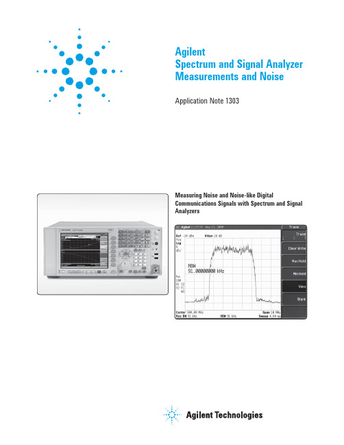
AgilentSpectrum and Signal Analyzer Measurements and NoiseApplication Note 1303Measuring Noise and Noise-like DigitalCommunications Signals with Spectrum and Signal Analyzers3 3 3 3 6 7 8 8 9 101214 14 14 16 16 17 18 18 19 19 19 19 19 20 21 2223 23 24 25 27 28Table of ContentsPart I: Noise Measurements IntroductionSimple noise—Baseband, Real, Gaussian Bandpassed noise—I and QMeasuring the power of noise with an envelope detector Logarithmic processingMeasuring the power of noise with a log-envelope scale Equivalent noise bandwidth The noise markerSpectrum analyzers and envelope detectorsCautions when measuring noise with spectrum and Signal analyzersPart II: Measurements of Noise-like Signals The noise-like nature of digital signalsChannel-power measurements Adjacent-Channel Power (ACP)Carrier power Peak-detected noise and TDMA ACP measurements Part III: Averaging and the Noisiness of Noise MeasurementsVariance and averagingAveraging a number of computed resultsSwept versus FFT analysis Zero spanAveraging with an average detectorMeasuring the power of noise with a power envelope scale The standard deviation of measurement noise ExamplesThe standard deviation of CW measurements Part IV: Compensation for Instrumentation Noise CW signals and log versus power detectionPower-detection measurements and noise subtraction Log scale ideal for CW measurements Bibliography Glossary of Terms2IntroductionNoise. It is the classical limitation of electronics.In measurements, noise and distortion limit the dynamic range of test results.In this four-part paper, the characteristics of noise and its direct measurement are discussed in Part I. Part II contains a discussion of the measurement of noise-like signals exemplified by digital CDMA and TDMA signals. Part III discusses using averaging techniques to reduce noise. Part IV is about compensating for the noise in instrumentation while measuring CW (sinusoidal) and noise-like signals.Simple noise—Baseband, Real, GaussianNoise occurs due to the random motion of electrons. The number of electrons involved is large, and their motions are independent. Therefore, the variation in the rate of current flow takes on a bell-shaped curve known as the Gaussian Probability Density Function (PDF) in accordance with the central limit theorem from statistics. The Gaussian PDF is shown in Figure 1.The Gaussian PDF explains some of the characteristics of a noise signal seen on a baseband instrument such as an oscilloscope. The baseband signal is a real signal; it has no imaginary components.Bandpassed noise—I and QIn RF design work and when using spectrum analyzers, we usually deal with signals within a passband, such as a com-munications channel or the resolution bandwidth (RBW, the bandwidth of the final IF) of a spectrum analyzer. Noise in this bandwidth still has a Gaussian PDF, but few RF instruments display PDF-related metrics.Instead, we deal with a signal’s magnitude and phase (polar coordinates) or I/Q components. The latter are the in-phase (I) and quadrature (Q) parts of a signal, or the real and imaginary components of a rectangular-coordinate representation of a signal. Basic (scalar) spectrum analyzers measure only the magnitude of a signal. We are interested in the characteristics of the magnitude of a noise signal.Part I: Noise Measurements3Figure 1. The Gaussian PDF is maximum at zero current and falls off away from zero,as shown (rotated 90 degrees) on the left. A typical noise waveform is shown on the right.We can consider the noise within a passband as being made of independent I and Q components, each with Gaussian PDFs. Figure 2 shows samples of I and Q com-ponents of noise represented in the I/Q plane. The sig-nal in the passband is actually given by the sum of the I magnitude, v I , multiplied by a cosine wave (at the center frequency of the passband) and the Q magnitude, v Q , mul-tiplied by a sine wave. But we can discuss just the I and Q components without the complications of the sine/cosine waves.Spectrum analyzers respond to the magnitude of the signal within their RBW passband. The magnitude, or envelope, of a signal represented by an I/Q pair is given by:v env =√(v I 2+v Q 2)Graphically, the envelope is the length of the vector from the origin to the I/Q pair. It is instructive to draw circles of evenly spaced constant-amplitude envelopes on the samples of I/Q pairs as shown in Figure 3.Figure 2. Bandpassed noise has a Gaussian PDF independently in both its I and Q components.–3–2–10123–3–2–1123–3–2–10123–3–2–101234If one were to count the number of samples within each annular ring in Figure 3, we would see that the area near zero volts does not have the highest count of samples. Even though the density of samples is highest there, this area is smaller than any of the other rings.The count within each ring constitutes a histogram of the distribution of the envelope. If the width of the rings were reduced and expressed as the count per unit of ring width, the limit becomes a continuous function instead of a histo-gram. This continuous function is the PDF of the envelope of bandpassed noise. It is a Rayleigh distribution in the envelope voltage, v, that depends on the sigma of the sig-nal; for v greater than or equal to 0PDF (v)= (v–σ2)exp (–1—2 (v–σ)2)The Rayleigh distribution is shown in Figure 4.Figure 3. Samples of I/Q pairs shown with evenly spaced constant-amplitude envelope circlesFigure 4. The PDF of the voltage of the envelope of a noise signal is a Rayleigh distribution.The PDF is zero at zero volts, even though the PDFs of the individual I and Q components aremaximum at zero volts. It is maximum for v=sigma.5Measuring the power of noise with an envelope detectorThe power of the noise is the parameter we usually want to measure with a spectrum analyzer. The power is the heating value of the signal. Mathematically, it is the time-average of v2(t)/R, where R is the impedance and v(t) is the voltage at time t.At first glance, we might like to find the average enve-lope voltage and square it, then divide by R. But finding the square of the average is not the same as finding the average of the square. In fact, there is a consistent under-measurement of noise from squaring the average instead of averaging the square; this under-measurement is 1.05 dB The average envelope voltage is given by integrating the product of the envelope voltage and the probability that the envelope takes on that voltage. This probability is theThe average power of the signal is given by an analogous expression with v2/R in place of the "v" part:p–= ∫∞(v–R2)PDF(v)dv =2σ–R2We can compare the true power, from the average power integral, with the voltage-envelope-detected estimate ofv2/R and find the ratio to be 1.05 dB, independent of s andThus, if we were to measure noise with a spectrum analyzer using voltage-envelope detection (the linear scale) and averaging, an additional 1.05 dB would need to be added to the result to compensate for averaging voltage instead of voltage-squared.6Logarithmic processingSpectrum Analyzers are most commonly used in their logarithmic (log) display mode, in which the vertical axis is calibrated in decibels. Let us look again at our PDF for the voltage envelope of a noise signal, but let’s mark the x-axis with points equally spaced on a decibel scale, in this case with 1 dB spacing. See Figure 5. The area under the curve between markings is the probability that the logof the envelope voltage will be within that 1 dB interval. Figure 6 represents the continuous PDF of a logged signal which we predict from the areas in Figure 5.Figure 6. The PDF of logged noise is about 30 dB wide and tilted toward the high end.7Measuring the power of noise with alog-envelope scaleWhen a spectrum analyzer is in a log (dB) displaymode, averaging of the results can occur in numerous ways. Multiple traces can be averaged, the envelope can be aver-aged by the action of the video filter, or the noise marker (more on this below) averages results across the x-axis. Some recently introduced analyzers also have a detector that averages the signal amplitude for the duration of a measurement cell.When we express the average power of the noise in deci-bels, we compute a logarithm of that average power. When we average the output of the log scale of a spectrum analyzer, we compute the average of the log. The log of the average is not equal to the average of the log. If we go through the same kinds of computations that we did com-paring average voltage envelopes with average power envelopes, we find that log processing causes an under-response to noise of 2.51 dB, rather than 1.05 dB.1The log amplification acts as a compressor for large noise peaks; a peak of ten times the average level is only 10 dB higher. Instantaneous near-zero envelopes, on the other hand, contain no power but are expanded toward negative infinity decibels. The combination of these two aspects of the logarithmic curve causes noise power to measure lower than the true noise power.Equivalent noise bandwidthBefore discussing the measurement of noise with a spec-trum analyzer noise marker, it is necessary to understand the RBW filter of a spectrum analyzer.The ideal RBW has a flat passband and infinite attenuation outside that passband. But it must also have good time domain performance so that it behaves well when signals sweep through the passband. Most spectrum analyzers use four-pole synchronously tuned filters for their RBW filters. We can plot the power gain (the square of the voltage gain) of the RBW filter versus frequency as shown in Figure 7. The response of the filter to noise of flat power spectral density will be the same as the response of a rectangular filter with the same maximum gain and the same areaunder their curves. The width of such a rectangular filter is the equivalent noise bandwidth of the RBW filter. The noise density at the input to the RBW filter is given by the output power divided by the equivalent noise bandwidth.1. Most authors on this subject artifi cially state that this factor is due to1.05 dB from envelope detection and another 1.45 dB from logarithmicamplifi cation, reasoning that the signal is fi rst voltage-envelopedetected, then logarithmically amplifi ed. But if we were to measure the voltage-squared envelope (in other words, the power envelope, which would cause zero error instead of 1.05 dB) and then log it, we wouldstill fi nd a 2.51 dB under-response. Therefore, there is no real point in separating the 2.51 dB into two pieces.8The ratio of the equivalent noise bandwidth to the –3 dB bandwidth (An RBW is usually identified by its –3 dB BW) is given by the following table:Filter type Application NBW/–3 dB BW4-pole sync Most SAs analog 1.128 (0.52 dB)5-pole sync Some SAs analog 1.111 (0.46 dB)Typical FFT FFT-based SAs 1.056 (0.24 dB)The noise markerAs discussed above, the measured level at the out put of a spectrum analyzer must be manipulated in order to repre-sent the input spectral noise density we wish to measure. This manipulation involves three factors, which may be added in decibel units:1. Under-response due to voltage envelope detection (add1.05 dB) or log-scale response (add2.51 dB).2. Over-response due to the ratio of the equivalent noisebandwidth to the –3 dB bandwidth (subtract 0.52 dB). 3. Normalization to a 1 Hz bandwidth (subtract 10 timesthe log of the RBW, where the RBW is given in unitsof Hz).Most spectrum analyzers include a noise marker that accounts for the above factors. To reduce the variance of the result, the Agilent 8590 and 8560 families of spectrum analyzers compute the average of 32 trace points cen-tered around the marker location. The Agilent ESA family, which allows you to select the number of points in a trace, compute the average over one half of a division centeredat the marker location. For an accurate measurement, you must be sure not to place the marker too close to a discrete spectral component.The final result of these computations is a measure of the noise density, the noise in a theoretical ideal 1 Hz band-width. The units are typically dBm/Hz.Figure 7. The power gain versus frequency of an RBW filter can be modeled by a rectangular filterwith the same area and peak level, and a width of the “equivalent noise bandwidth.”9Spectrum analyzers and envelope detectorsA simplified block diagram of a spectrum analyzer is shown in Figure A.The envelope detector/logarithmic amplifier block is shown configured as they are used in the Agilent 8560 E-Series spectrum analyzers. Although the order of these two cir-cuits can be reversed, the important concept to recognize is that an IF signal goes into this block and a baseband signal (referred to as the “video” signal because it was used to deflect the electron beam in the original analog spectrum analyzers) comes out.Notice that there is a second set of detectors in the block diagram: the peak/pit/sample hardware of what is normally called the detector mode of a spectrum analyzer. These display detectors are not relevant to this discussion, and should not be confused with the envelope detector.The salient features of the envelope detector are two:1. The output voltage is proportional to the input voltage envelope.2. The bandwidth for following envelope variationsis large compared to the widest RBW.Figure A. Simplified spectrum analyzer block diagramFigure B. Detectors: a) half-wave, b) full-wave implemented as a “product detector,” c) peak. Practical implementations usually have their gain terms implemented elsewhere, and implement buffering after the filters that remove the residual IF carrier and harmonics. The peak detector must be cleared; leakage through a resistor or a switch with appropriate timing are possible clearing mechanisms.10Figure B shows envelope detectors and their associated waveforms in (a) and (b). Notice that the gain required to make the average output voltage equal to the r.m.s. voltage of a sinusoidal input is different for the different topologies. Some authors on this topic have stated that “an envelope detector is a peak detector.” After all, an idealized detector that responds to the peak of each cycle of IF energy inde-pendently makes an easy conceptual model of ideal behav-ior. But real peak detectors do not reset on each IF cycle. Figure B, part c, shows a typical peak detector with its gain calibration factor. It is called a peak detector because its response is proportional to the peak voltage of the signal. If the signal is CW, a peak detector and an envelope detec-tor act identically. But if the signal has variations in its envelope, the envelope detector with the shown LPF (low pass filter) will follow those variations with the linear, time-domain characteristics of the filter; the peak detector will follow nonlinearly, subject to its maximum negative-going limit, as demonstrated in Figure C. The nonlinearity will make for unpredictable behavior for signals with noise-like statistical variations. A peak detector may act like an envelope detector in the limit as its resistive load dominates and the capacitive load is minimized. But practically, the nonideal voltage drop across the diodes and the heavy required resistive load make this topology unsuitable for envelope detection. All spectrum analyzers use envelope detectors, some are just misnamed.Figure C. An envelope detector will follow the envelope of the shown signal, albeit with the delay and filtering action of the LPF used to remove the carrier harmonics. A peak detector is subject to negative slew limits, as demonstrated by the dashed line it will follow across a response pit. This drawing is done for the case in which the logarithmic amplification precedes the envelope detection, oppositeto Figure A; in this case, the pits of the envelope are especially sharp.Cautions when measuring noise with spectrum and signal analyzersThere are three ways in which noise measurements can look perfectly reasonable on the screen of a spectrum ana-lyzer, yet be significantly in error.Caution 1, input mixer level. A noise-like signal of very high amplitude can overdrive the front end of a spectrum ana-lyzer while the displayed signal is within the normal display range. This problem is possible whenever the bandwidth of the noise-like signal is much wider than the RBW. The power within the RBW will be lower than the total power by about ten times the log of the ratio of the signal band-width to the RBW. For example, an IS-95 CDMA signal with a 1.23 MHz bandwidth is 31 dB larger than the power in a 1 kHz RBW. If the indicated power with the 1 kHz RBW is –20 dBm at the input mixer (i.e., after the input attenuator), then the mixer is seeing about +11 dBm. Most spectrum analyzers are specified for –10 dBm CW signals at their input mixer; the level below which mixer compression is specified to be under 1 dB for CW signals is usually 5 dB or more above this –10 dBm. The mixer behavior with Gaussian noise is not guaranteed, especially because its peak-to-average ratio is much higher than that of CW signals.Keeping the mixer power below –10 dBm is a good practice that is unlikely to allow significant mixer nonlinearity. Thus, caution #1 is: Keep the total power at the input mixer at or below –10 dBm.Figure D. In its center, this graph shows three curves: the ideal log amp behavior, that of a log amp that clips at its maximum and minimum extremes, and the average response to noise subject to that clipping. The lower right plot shows, on expanded scales, the error in average noise response due to clipping at the positive extreme. The average level should be kept 7 dB below the clipping level for an error below 0.1 dB. The upper left plot shows, with an expanded vertical scale, the corresponding error for clipping against the bottom of the scale. The average level must be kept 14 dB above the clipping level for an error below 0.1 dB.Caution 2, overdriving the log amp. Often, the level dis-played has been heavily averaged using trace averaging or a video bandwidth (VBW) much smaller than the RBW. In such a case, instantaneous noise peaks are well above the displayed average level. If the level is high enough that the log amp has significant errors for these peak levels, the average result will be in error. Figure D shows the error due to overdriving the log amp in the lower right corner, based on a model that has the log amp clipping at the topof its range. Typically, log amps are still close to ideal for a few dB above their specified top, making the error model conservative. But it is possible for a log amp to switch from log mode to linear (voltage) behavior at high levels,in which case larger (and of opposite sign) errors to those computed by the model are possible. Therefore, caution #2 is: Keep the displayed average log level at least 7 dB below the maximum calibrated level of the log amp.Caution 3, underdriving the log amp. The opposite of the overdriven log amp problem is the underdriven log amp problem. With a clipping model for the log amp, the results in the upper left corner of Figure D were obtained. Caution #3 is: Keep the displayed average log level atleast 14 dB above the minimum calibrated levelof the log amp.In Part I, we discussed the characteristics of noise and its measurement. In this part, we will discuss three different measurements of digitally modulated signals, after showing why they are very much like noise.The noise-like nature of digital signalsDigitally modulated signals can be created by clocking a Digital-to-Analog Converter (DAC) with the symbols (a group of bits simultaneously transmitted), passing the DAC output through apre-modulation filter (to reduce the trans-mitted bandwidth), and then modulating the carrier with the filtered signal. See Figure 8. The resulting signal is obvi-ously not noise-like if the digital signal is a simple pattern. It also does not have a noise-like distribution if the band-width of observation is wide enough for the discrete nature of the DAC outputs to significantly affect the distribution of amplitudes.But, under many circumstances, especially test conditions, the digital signal bits are random. And, as exemplified by the channel power measurements discussed below, the observation bandwidth is narrow. If the digital update period (the reciprocal of the symbol rate) is less than one-fifth the duration of the majority of the impulse response of the resolution bandwidth filter, the signal within the RBW is approximately Gaussian according to the central limit theorem.A typical example is IS-95 CDMA. Performing spectrum analysis, such as the adjacent-channel power ratio (ACPR) test, is usually done using the 30 kHz RBW to observe the signal. This bandwidth is only one-fortieth of the symbol clock rate (1.23 Msymbols/s), so the signal in the RBW is the sum of the impulse responses to about forty pseudo-random digital bits. A Gaussian PDF is an excellent approxi-mation to the PDF of this signal.Channel-power measurementsMost modern spectrum analyzers allow the measurement of the power within a frequency range, called the channel bandwidth. The displayed result comes from the computa-tion:P ch =(B s–B n)(1–N) n2i=n1∑10(p i/10)Pch is the power in the channel, Bs is the specified bandwidth (also known as the channel bandwidth), Bnis the equivalent noise bandwidth of the RBW used, Nis the number of data points in the summation, pi is the sample of the power in measurement cell i in dB units (if pi is in dBm, Pch is in milliwatts). n1 and n2 are the end-points for the index i within the channel bandwidth, thus N=(n2 – n1) + 1.Part II: Measurements of Noise-like Signals Figure 8. A simplified model for the generation of digital communications signals.The computation works well for CW signals, such as from sinusoidal modulation. The computation is a power-sum-ming computation. Because the computation changes the input data points to a power scale before summing, there is no need to compensate for the difference between the log of the average and the average of the log as explained in Part I, even if the signal has a noise-like PDF (probability density function). But, if the signal starts with noise-like statistics and is averaged in decibel form (typically with a VBW filter on the log scale) before the power summation, some 2.51 dB under-response, as explained in Part I,will be incurred. If we are certain that the signal is of noise-like statistics, and we fully average the signal before per-forming the summation, we can add 2.51 dB to the result and have an accurate measurement. Furthermore, the aver-aging reduces the variance of the result.But if we don’t know the statistics of the signal, the best measurement technique is to do no averaging before power summation. Using a VBW ≥ 3RBW is required for insignifi-cant averaging, and is thus recommended. But the band-width of the video signal is not as obvious as it appears.In order to not peak-bias the measurement, the detector must be used. Spectrum analyzers have lower effective video bandwidths in sample detection than they do in peak detection mode, because of the limitations of the sample-and-hold circuit that precedes the A/D converter. Examples include the Agilent 8560E-Series spectrum analyzer family with 450 kHz effective sample-mode video bandwidth, and a substantially wider bandwidth (over 2 MHz) in the Agilent ESA-E Series spectrum analyzer family.Figure 9 shows the experimentally determined relationship between the VBW:RBW ratio and the under-response of the partially averaged logarithmically processed noise sig-nal.However, the Agilent PSA is an exception to the relation-ship illustrated by Figure 9. The Agilent PSA allows us to directly average the signal on a power scale. Therefore, if we are not certain that our signal is of noise-like statistics, we are no longer prohibited from averaging before power summation. The measurement may be taken by either using VBW filtering on a power scale, or using the average detec-tor on a power scale.Figure 9. For VBW ≥ 3 RBW, the averaging effect of the VBW filter does not significantly affect power-detection accuracy.Adjacent-Channel Power (ACP)There are many standards for the measurement of ACP with a spectrum analyzer. The issues involved in most ACP measurements are covered in detail in an article in Microwaves & RF, May, 1992, "Make Adjacent-Channel Power Measurements." A survey of other standards is available in "Adjacent Channel Power Measurements in the Digital Wireless Era" in Microwave Journal, July, 1994.For digitally modulated signals, ACP and channel-power measurements are similar, except ACP is easier. ACP is usually the ratio of the power in the main channel to the power in an adjacent channel. If the modulation is digital, the main channel will have noise-like statistics. Whether the signals in the adjacent channel are due to broadband noise, phase noise, or intermodulation of noise-like signals in the main channel, the adjacent channel will have noise-like statistics. A spurious signal in the adjacent channelis most likely modulated to appear noise-like, too, but a CW-like tone is a possibility.If the main and adjacent channels are both noise-like, then their ratio will be accurately measured regardless of whether their true power or log-averaged power (or any partially averaged result between these extremes) is mea-sured. Thus, unless discrete CW tones are found in the signals, ACP is not subject to the cautions regarding VBW and other averaging noted in the section on channel power above.But some ACP standards call for the measurement of abso-lute power, rather than a power ratio. In such cases, the cautions about VBW and other averaging do apply.Carrier powerBurst carriers, such as those used in TDMA mobile sta-tions, are measured differently than continuous carriers. The power of the transmitter during the time it is on is called the "carrier power."Carrier power is measured with the spectrum analyzerin zero span. In this mode, the LO of the analyzer doesnot sweep, thus the span swept is zero. The display then shows amplitude normally on the y axis, and time on the x axis. If we set the RBW large compared to the bandwidth of the burst signal, then all of the display points include all of the power in the channel. The carrier power is computed simply by averaging the power of all the display points that represent the times when the burst is on. Depending on the modulation type, this is often considered to be any point within 20 dB of the highest registered amplitude. (A trig-ger and gated spectrum analysis may be used if the carrier power is to be measured over a specified portion of a burst-RF signal.)Using a wide RBW for the carrier-power measurement means that the signal will not have noise-like statistics. It will not have CW-like statistics, either, so it is still wise to set the VBW as wide as possible. But let’s consider some examples to see if the sample-mode bandwidthsof spectrum analyzers are a problem.For PDC, NADC and TETRA, the symbol rates are under25 kb/s, so a VBW set to maximum will work well. It will also work well for PHS and GSM, with symbol rates of 380 and 270 kb/s. For IS-95 CDMA, with a modulation rate of 1.23 MHz, we could anticipate a problem with the 450 kHz effective video bandwidth discussed in the section on chan-nel power above. Experimentally, an instrument with 450 kHz BW experienced a 0.6 dB error with an OQPSK (mobile) burst signal.。
频谱分析仪相位噪声测量原理(图文)论文导读:相位噪声是衡量信号源频稳质量的主要技术指标,专用的相位噪声测试系统设备量庞大,价格昂贵,用频谱分析仪测量相位噪声是一种简单直接的测量方法,而频谱分析仪作为通用的测量仪器,广泛应用于普通实验室和雷达、通信、电子设备的生产使用中。
针对某频谱仪开发的相位噪声测试选件不仅能为用户自动完成相位噪声测量功能,并提供多样化的测试报表,使相位噪声的测量变得简单、快捷。
关键词:频谱分析仪,相位噪声1引言相位噪声是衡量信号源频稳质量的主要技术指标,专用的相位噪声测试系统设备量庞大,价格昂贵,用频谱分析仪测量相位噪声是一种简单直接的测量方法,而频谱分析仪作为通用的测量仪器,广泛应用于普通实验室和雷达、通信、电子设备的生产使用中。
随着现代频谱分析仪性能(动态范围、分辨率、内部噪声)的不断提高,给直接频谱分析法创造了有利条件。
针对某频谱仪开发的相位噪声测试选件不仅能为用户自动完成相位噪声测量功能,并提供多样化的测试报表,使相位噪声的测量变得简单、快捷。
本文重点介绍了用频谱分析仪测量相位噪声的原理与相噪选件的实现。
2相位噪声的基本概念频率稳定度是信号源的重要指标,指在一定的时间间隔内,信号源输出频率的变化。
根据时间间隔的长短可分为长期稳定度和短期稳定度。
短期稳定度在时域表现为在波形零点处的抖动,可以用相对频率起伏(阿伦方差)来描述,在频域则用相位噪声来表征。
一个有幅度和频率起伏的正弦波可表示为:υ(t)= [V0 +a(t)]sin[2πf0t+φ(t)] (1)式中a(t)= 幅度噪声,φ(t)= 相位噪声通常信号源输出的信号都会有调幅噪声a(t) <<V0,它不直接造成频率起伏或相位起伏,不影响频率稳定度,在这里可以忽略不计。
信号的噪声边带主要由调相噪声引起,实际测量中常用单边带相位噪声(SSB)来表示短期频率稳定度,美国国家标准局把SSB相位噪声(L(ƒm))定义为:偏离载波频率ƒm Hz,在1Hz带宽内一个相位调制边带的功率PSSB与总的信号功率Ps之比,即L(ƒm)= = (2)L(ƒm)是相位噪声最常用的表示形式,通常用相对于载波波段1Hz带宽的对数表示(dBc/Hz)。