User Manual
- 格式:pdf
- 大小:980.23 KB
- 文档页数:47

User Manual - A Guide to Using Instructions IntroductionThe user manual is a comprehensive guide that provides detailed instructions for using a particular product or service effectively. It is designed to assist users in understanding the features, functions, and operation of the product, thus enabling them to make the most of it. This document serves as a guide to understanding and utilizing user manuals effectively.Importance of User ManualsUser manuals play a crucial role in facilitating the use of a product. They provide step-by-step instructions, troubleshooting guidance, and necessary information about safety precautions. User manuals act as a bridge between the user and the product, allowing the user to navigate through its functionalities efficiently. They enhance user experience by offering solutions to common issues and offering tips for optimized usage.Structure of User ManualsUser manuals typically have a standardized structure to ensure clarity and ease of use. The following sections are commonly found in user manuals:1.Introduction: This section provides an overview of the product,highlighting its features and benefits. It sets the tone for the user manual and creates interest in the product.2.Safety Information: This section emphasizes safety precautions forusing the product. It includes warnings, cautions, and instructions to ensure the user’s safety during operation.3.Getting Started: In this section, users are guided through the initialsetup and installation process. It includes information about essentialrequirements and the first steps to take when starting to use the product.4.Product Operation: This section provides detailed instructions onhow to operate the product. It explains the functions of various buttons,controls, and settings, allowing users to perform specific tasks with ease.5.Troubleshooting: When users encounter issues or errors, thissection provides step-by-step guidance to diagnose and resolve commonproblems. It is essential for users to refer to this section before seeking further support.6.Maintenance and Care: Proper maintenance helps optimize thelifespan and performance of the product. This section outlines maintenancetasks, cleaning procedures, and any additional care requirements.7.Frequently Asked Questions: Compiled from the most commoninquiries, this section addresses specific queries that users may encounterduring product usage. It provides quick solutions to avoid unnecessary support requests.8.Contact Information: Finally, user manuals include contact detailsfor customer support, including phone numbers, email addresses, and online forums. This information acts as a resource for users experiencing complexissues or requiring additional assistance.Tips for Using User Manuals EffectivelyTo make the most of a user manual, consider the following tips:1.Read the Manual: Thoroughly read the user manual before operatingthe product for the first time. This will familiarize you with its features,capabilities, and safety instructions.2.Follow Step-by-Step: Go through the instructions systematically,following each step carefully. Skipping or overlooking steps may lead todifficulties or even damage the product.3.Highlight Important Information: Use highlighters or sticky notes tomark critical instructions, warnings, or troubleshooting solutions. This willallow for easy reference in the future.4.Consult Troubleshooting: When facing issues, refer to thetroubleshooting section before seeking external support. Often, minor issues can be resolved independently with the help of the manual.5.Keep the User Manual Handy: It is advisable to keep the usermanual in a safe place where it is easily accessible. This ensures that it isreadily available whenever required, even after an extended period of usage.6.Update the Manual: In case of any updates or revisions to theproduct, check the manufacturer’s website for the latest version of the usermanual. Keeping up-to-date ensures that you have the most accurateinformation regarding the product.ConclusionUser manuals are indispensable tools for understanding and operating products effectively. By following the instructions provided, users can maximize the benefitsand avoid potential issues. Remember, a well-utilized user manual enhances product experience and promotes user satisfaction.。
Danfoss Hexact:User Manual(Version 2.1.1)Any questions or comments can be directed to: SWHELP@Danfoss Hex China (Hangzhou) R&D CenterDistrict EnergyTel: 0086 573 86808800Jan, 2014Table of Contents1INSTALLATION AND REGISTRATION OF DANFOSS HEXACT (1)2OVERVIEW OF DANFOSS HEXACT (2)3DESIGN CALCULATION-FOR DEN PART (3)4RATING CALCULATION -FOR DEN PART (11)5PERFORMANCE CALCULATION (13)6DESIGN CALCULATION-RC PART (13)7RATING CALCULATION-RC-PART (15)8PERFORMANCE CALCULATION-RC Part (16)9FILE (17)10SETTINGS (17)11WINDOW (17)12HELP (17)13NEW (17)14OPEN (17)15SAVE (17)16SAVING IN EXCEL (17)17REPROTOUT (18)18UNITS (18)19LANGUAGE (18)20STOCK (18)21MULTICALC (19)22 D. P. CALC (20)23FLUID EDITOR (21)24CURRENCY AND EXCHANGE RATE (22)25USER DEFINED UNITS (23)26MORE HELP (24)27WARNING MESSAGES (24)28ERROR MESSAGE OR NO SOLUTION (24)29SPECIAL FUNCTIONS & APPLICATIONS for RC PRODUCTS (25)1INSTALLATION AND REGISTRATION OF DANFOSS HEXACT1.1Minimum PC System RequirementsPC Hardware✧ 1.5 GHz Intel© processor or equivalent (2.0 GHz or faster recommended)✧ 1 GB RAM (2 GB or more recommended)✧20 MB available hard driveOperating system tested:✧Windows XP (SP3)✧Win7 (32-bit)✧Win7 (64-bit)Additional software:✧.net framework 3.5✧Microsoft Office1.2InstallationDownload the installation package to your computer. The installation package consists of two files:✧Danfoss Hexact(*.*.*).msiIf you have .net framework installed on your computer, please double click the file “Danfoss Hexact(*.*.*).msi” for fast installation. After installation, you will find a shortcut of the Hexact on the desktop.1.3RegistrationWhen you first time run the Hexact, you will see the following Figure 1error message.Figure 1 - Message for registrationThen the following registration window will be popped up automatically, such as Figure 2:Figure 2 - Registration code generationRegister your software at /hexact or contact your local Danfoss sales representative. After registration you will be provided a license file “registry.ini”.Then please copy “registry.ini” to the installation folder (e.g. default installation folder is C:\ Danfoss Hexact) and try to run the Hexact again. If you still cannot open the software, please restart your PC or contact the support team for further assistance.Note that there are three registration code with different last number for one PC.2OVERVIEW OF DANFOSS HEXACTWhen you open up the Hexact, a “New application” window will be brought up automatically. And the whole applications are as shown in Figure . You can select different applications including Heat pump, Chiller, Universal RC for RC products and X-Standard, X OEM, XGC, X Traco, X Europe for DEN products. For certain application, you can further find available functions the Hexact can perform, e.g. evaporator, condenser, etc., in Heat pump and Chiller application, Single phase, Cascade Condenser, etc., in RC General application, and XB, XG in X-Standard.Note: the ‘New application’ will vary based on the permission.Figure 3 - New applicationIf it is the first time you open up Hexact and will do some DEN calculation. A “Personal Setting” warning massage (shown in Figure ) will be brought up. Please click “OK” and then a “Personal Setting” dialogue box will be brought up (shown in Figure ), you can input your information in it. Please note that the items include “*”are mandatory.You can modify your personal information by click menu “Setting-Personal Setting” (as shown in Figure6).Note: The “Region” has Europe only for version 2.1.1 and the personal setting dialogue box is just for DEN part.Figure 4 - Personal Setting Warning MassageFigure 5 - Personal Setting Dialogue BoxFigure 6 - Setting Personal Setting3DESIGN CALCULATION-FOR DEN PARTThe design calculation helps the user find out the appropriate heat exchangers subject to the given inputs. For the same products it will find out the most optimal solution.Let’s take a case as example for X Standard products and select ‘X Standard’ –‘XG Gasketed HEX’ button, then you will goes into the design calculation duty screen. Users can also use functions such as “New”, “Open”, “Save”, “SavingInExcel”, “ReportOut”, “Units”, “MultiCalc”, etc., In addition, as for functions “Fluid Editor” , only authorized users have access to them (as shown in Figure 7).Figure 7 – Design Calculation Duty Screen3.1Design Duty screenUsers can input the condition data into ‘Input window’ of duty screen, the inputs of duty screen include:✧Heat exchanger:The type of heat exchanger, user can further pick the available products.Optimum-XB/XG/XGC/TR will calculated with all available products.✧Load: Required heat load.✧Surface margin:The positive difference between the calculated required heat transfer surfaceand the actual heat transfer surface of the selected heat exchanger✧Fluid: user can select refrigerant or brine mediums for each side.✧Inlet & Outlet temperatures: Inlet & Outlet temperatures of side 1 & side 2✧Phase and Concentration: will pop up for special brine (as shown in Figure 8)✧Flow rate: Mass or volumetric flow rate.✧Max pressure drops: The max pressure drops allowed for side1 & side2✧Pass Number: Include Auto/1pass/2pass and 2-AC if users choose 2-AC in ‘Config tab’.✧Tab Selection Keys: Include ‘Temp’,‘Option’, ‘Config’, ‘Results’, and users can open differenttabs by click these keys.✧Calculate: Users can do a calculation by click this button.✧Real Outlet Calculate: Users can do a real outlet calculation by click this button. And the outlettemperature will be actual temperature based on the input condition.Figure 8 –Phase and Concentration input box3.2Temperature Profile TabUsers can input the inlet & outlet temperatures in duty screen, and click ‘Temp tab key’, a temperature profile tab will be pop up (as shown in Figure9), and if you don’t need the temperature profile tab, click ‘Temptab key’ again, it will be disappeared.Figure 9 –Temperature ProfileFigure 10 – Option Tab3.3Option tabUsers can click ‘Option tab key’ to open the option tab, and filer the available products (as shown in Figure 10). The options of option tab include:✧Price List: Users can select price list✧Fouling factor: The heat resistance which can offset the surface margin✧Flow type: Counter current or co-current✧Max Units: In parallel/series cam allows the user to narrow down the selection with unit amountlimit of products.✧Size limitation: Allow the user to narrow down the selection with the products size limit.✧Plate Material: Allow users to filter by available plate material to find the available products.‘Auto’ means select all available products.✧Plate Thickness: Allow users to filter by available plate Thickness to find the available products.‘Auto’ means select all available products.✧Gasket Material: Allow users to filter by available gasket material to find the available products.‘Auto’ means select all available products.✧Delivery Concept:Allow users to filter by available delivery concept to find the availableproducts. ‘A’ means, ‘B’ means, ‘C’ means,‘Auto’ means select all available products.✧Certification/Approve Type: Allow users to filter by available certification/approve type to findthe available products.✧Design Pressure (Max): Allow users to filter by design pressure to find the available products.If the text box is blank, it means ‘Auto’ and will select all available products.✧Design Temp (Max/Min):Allow users to filter by max/min design temperature to find theavailable products. If the text box is blank, it means ‘Auto’ and will select all available products.✧Max Port Velocity:✧Connection Type:Allow users to filter by available connection type to find the availableproducts. ‘Auto’ means select all available products.✧Connection Size: Allow users to filter by available connection size to find the available products.‘Auto’ means select all available products.Note: Users can click ‘Option’ again to close the option tab.3.4Configuration TabUsers can click ‘Config’tab key’to open the configuration tab, and choose standard or tailor made calculation mode. User can set pass Number in this tab too (as shown in figure 11).The items of configuration tab include:✧Grouping: Users can only set pass number in design mode.✧Standard number of plates: Users can checked this item to calculate standard case only.✧Mixed is allowed: This item will be enabled if the product allowed mixed channel, and users canchecked this item to do mixed channel calculation.✧One channel more: Users can specified one channel more for side1/side2 by checked this item.✧Has bigger hole: This item will be enabled if the product allowed one side hole bigger than theother side. And users can checked this item to calculation with one side hole bigger than the otherside.✧Has bigger gap: This item will be enabled if the product allowed one side gap bigger than theother side. And users can checked this item to calculation with one side gap bigger than the otherside.✧2-AC: Users can checked this item to do after cooling calculation. And the after cooling dialoguebox will appeared in duty screen. (as shown in figure 12)Figure 11 –Configuration TabFigure 12 –After Cooling Dialogue Box3.5Result TabUsers can click ‘Results’ tab key to open the results tab (as shown in figure 13).Users can find the general information of available solutions on the top, and detail information of the selected solution on the bottom.Users can select different information of the selected solution by click the result information button. It’s included Duty&Media, Mechanical Configuration, Dimension data, Accessories, Punch List, BOM.Figure 13 –Results Tab✧ Duty&MediaAs shown in Figure 13, Duty&Media tab will be shown by click “Duty&Media” button.Users can find the calculated parameters, properties of fluid and some technical information.✧ Mechanical ConfigurationAs shown in Figure 14, Mechanical Configuration tab will be shown by click “Mechanical Configuration”button.User can finish/change the available configurations of the HEX by choice of connections, plate material, gaskets etc. And make it ready for final prices and quote.Please note that the BOM and Punch List will be updated too, if users change the configurations.The items of Mechanical Configuration tab include:Plate Material: Users can change the available plate material to find the final prices and quote.Plate Thickness:Users can change the available plate thickness to find the final prices and quote.Please note that, if the plate thickness changed, then the design pressure will be changed to the relatedvalue.Gasket Material: Users can change the available gasket material to find the final prices and quote.Gasket Attachment: Users can change the available gasket attachment to find the final prices and quote.Design Pressure: Users can change the available design pressure to find the final prices and quote.Please note that, if the plate thickness changed, then the plate thickness will be changed to the relatedvalue.Extension:Extension means the number of plates users want to extend. Users can change the extension value to 10%, 20%, 30%, then the frame and price might be updated.Connection Type: Users can change the available connection type to find the final prices and quote.Connection Size: Users can change the available connection size to find the final prices and quote.Figure 14 –Mechanical Configuration TabFigure 15 –Dimension Data Tab✧Dimension data:As shown in Figure 15, Dimension data tab will be shown by click “Dimension data” button. Users can find the dimension data and drawings.✧Accessories:As shown in Figure 16, Accessories tab will be shown by click “Accessories” button. Users can select the available accessories for the selected solution by change the number of Pcs.Please note that the price of the selected accessories will be not included in the total GPL.Figure 16 –Accessories Tab✧Punch List:As shown in Figure 17, Punch List Tab will be shown by click “Punch List” button.Punch List Tab shows all plates in the selected HEX ranked according to its place in the plate pack and is used in production for assembly of the unit.Figure 17 –Punch List TabBOM:As shown in Figure 18, BOM Tab will be shown by click “BOM” button.BOM is list of materials used to build the selected GHEX. The list will include number of components and detail information (Danfoss Code, category, Description) for each type of component.Figure 18 –BOM Tab4RATING CALCULATION -FOR DEN PARTAs shown in Figure 19. Users can click rating to go to rating mode. The inputs of rating mode is the same as design mode in duty screen, but do not need “Max pressure drop”.Figure 19 –Rating Mode Duty ScreenFor rating calculation, Number of plates is necessary, users can input the grouping information in “config tab”.Figure 20 ~25 shows how to input the number of plates and pass number into “config tab”.✧Pure Channel:Select pass number, and inputs channel number & channel Type (as shown in figure 20). If users click “standard number of plates”, a “number of plates” drop down list will be appeared in duty screen, and users can select the standard number of plates.Figure 20 –Tailor Made Pure ChannelFigure 21 – Standard Case Pure Channel✧Mixed Channel:User can input mixed channel information by click “Mixed is allowed” first, then select “Mixed channel”tab. As shown in figure 22, users can select pass number, and inputs channel number & channel Type in “Mixed channel” tab✧Asymmetric Channel:Asymmetric channel will be activated by 2 pass number case. Users can select the pass number as 2 in duty screen, then input asymmetric channel information into “Asymmetric channel” tab (as shown in figure 23)Figure 22 –Mixed ChannelFigure 23 –Asymmetric ChannelThe Rating calculation outputs are similar to those of design calculation. Please refer to section 3 “Design Calculation-DEN Part”.5PERFORMANCE CALCULATIONThe performance calculation helps users figure out one outlet parameter based on zero surface margin. And “Performance” function will cost more time than “Rating” function to response.The input is similar to Rating.The outputs are similar to those of design calculation, except:✧Surface margin is zero, which is the convergence criterion of performance calculation.✧ Unknown temperature is calculated in order to achieve zero margin.6DESIGN CALCULATION-RC PARTThe design calculation helps the user find out the appropriate heat exchangers subject to the given inputs.As shown in Figure 24Figure 23 - Calculation inputs and outputs for EvaporatorThe inputs include:✧The type of heat exchanger: MPHE and BPHE is available for RC products calculation. Foreach type of heat exchangers, user can further pick the available products.✧Size limitation allows the user to narrow down the selection with the products size limit✧Max Units in parallel/series cam allows the user to narrow down the selection with unit amountlimit of products.✧Flow type: counter current or co-current✧Fluid: user can select refrigerant or brine mediums.✧Phase and Pressure / Saturation temp is available for special application✧Concentration is available for special brine✧Load✧Surface margin the positive difference between the calculated required heat transfer surface andthe actual heat transfer surface of the selected heat exchanger✧Fouling factor is the heat resistance which can offset the surface margin✧Mass / Volumetric flow rate✧Pass number✧Max pressure drops of both sides is necessarySpecial in Evaporator / Economizer:✧Liq Temp at Exp Vlv / Inlet quality is used to define the inlet state of refrigerant✧Evaporating temperature is defined as outlet evaporating temperature of refrigerant side✧Refrigerant leaving superheat / Outlet quality is used to define the outlet state of refrigerant✧Inlet & outlet temperatures on liquid sideSpecial in Condenser:✧Inlet temperature / Inlet quality is used to define the inlet state of refrigerant✧Condensing temperature is defined as inlet of refrigerant side✧Subcooling / Outlet quality is used to define the outlet state of refrigerant✧Inlet & outlet temperatures on liquid sideSpecial in Cascade Condenser:✧Inlet temperature / Inlet quality is used to define the inlet state of Condensing side✧Dew temperature is defined as inlet condensing temperature of Condensing side and the outletevaporating temperature of Evaporating side✧Subcooling / Outlet quality is used to define the outlet state of Condensing side✧Liq Temp at Exp Vlv / Inlet quality is used to define the inlet state of Evaporating side✧Superheating / Outlet quality is used to define the outlet state of Evaporating sideSpecial in Subcooler / Desuperheater / HeatRecovery :✧Inlet & Outlet temperatures of Ref side & Fluid sideSpecial in Single phase:✧Inlet & Outlet temperatures of side 1 & side 2The outputs include:✧For each heat exchanger, the heat exchanger name is followed by the price factor (if the valueexists), surface margin, units in parallel/series, plate number per unit, number of channels forrefrigerant and liquid, total heat transfer area, overall heat transfer coefficient, and pressuredrops.✧“Technical data” and “Dimensional data” are presented in the bottom field. The “Technicaldata” tab consists of output parameters and fluid properties. The “Dimensional data” tab posts thefigures and data of heat exchanger dimension.NOTES: While using Optimum MPHE and Optimum BPHE in “Design” function, much longer time will be took to get all solutions than other single cases.7RATING CALCULATION-RC-PARTThe rating calculation helps users rate the selected heat exchangers subject to the given inputs.The inputs include:✧Heat exchanger type should be specified✧Units in parallel or series✧Flow type: counter current or co-current✧Fluid: user can select refrigerant or brine mediums✧Phase and Pressure / Saturation temp is available for special application✧Concentration is available for special brine✧Load✧Mass / Volumetric flow rate✧Pass number✧Number of plates is necessarySpecial in Evaporator / Economizer:✧Liq Temp at Exp Vlv / Inlet quality is used to define the inlet state of refrigerant✧Evaporating temperature is defined as outlet evaporating temperature of refrigerant side✧Refrigerant leaving superheat / Outlet quality is used to define the outlet state of refrigerant✧Inlet & outlet temperatures on liquid sideSpecial in Condenser:✧Inlet temperature / Inlet quality is used to define the inlet state of refrigerant✧Condensing temperature is defined as inlet of refrigerant side✧Subcooling / Outlet quality is used to define the outlet state of refrigerant✧Inlet & outlet temperatures on liquid sideSpecial in Cascade Condenser:✧Inlet temperature / Inlet quality is used to define the inlet state of Condensing side✧Dew temperature is defined as inlet condensing temperature of Condensing side and the outletevaporating temperature of Evaporating side✧Subcooling / Outlet quality is used to define the outlet state of Condensing side✧Liq Temp at Exp Vlv / Inlet quality is used to define the inlet state of Evaporating side✧Superheating / Outlet quality is used to define the outlet state of Evaporating sideSpecial in Subcooler / Desuperheater / HeatRecovery :✧Inlet & Outlet temperatures of Ref side & Fluid sideSpecial in Single phase:✧Inlet & Outlet temperatures of side 1 & side 2The outputs are similar to those of design calculation. Please refer to section 6 “Design Calculation-RC Part”.8PERFORMANCE CALCULATION-RC PartThe performance calculation helps users figure out one outlet parameter based on zero surface margin. And “Performance” function will cost more time than “Rating” function to response.The inputs include:✧Heat exchanger type should be specified✧Units in parallel or series✧Flow type: counter current or co-current✧Fluid: user can select refrigerant or brine mediums✧Phase and Pressure / Saturation temp is available for special application✧Concentration is available for special brine✧Load✧Mass / Volumetric flow rate✧Pass number✧Number of plates is necessarySpecial in Evaporator / Economizer:✧Liq Temp at Exp Vlv / Inlet quality is used to define the inlet state of refrigerant✧Refrigerant leaving superheat / Outlet quality is used to define the outlet state of refrigerant✧Inlet & outlet temperatures on liquid sideSpecial in Condenser:✧Inlet temperature / Inlet quality is used to define the inlet state of refrigerant✧Subcooling / Outlet quality is used to define the outlet state of refrigerant✧Inlet & outlet temperatures on liquid sideSpecial in Cascade Condenser:✧Inlet temperature / Inlet quality is used to define the inlet state of Condensing side✧Dew temperature is defined as outlet evaporating temperature of Evaporating side✧Subcooling / Outlet quality is used to define the outlet state of Condensing side✧Liq Temp at Exp Vlv / Inlet quality is used to define the inlet state of Evaporating side✧Superheating / Outlet quality is used to define the outlet state of Evaporating sideSpecial in Subcooler / Desuperheater / HeatRecovery :✧Inlet & Outlet temperatures of Fluid side✧Inlet temperatures of Ref sideSpecial in Single phase:✧Inlet & Outlet temperatures of side 2✧Inlet temperatures of side 1The outputs are similar to those of design calculation, except:✧Surface margin is zero, which is the convergence criterion of performance calculation.✧Unknown temperature are calculated in order to achieve zero surface margin.9FILEThe FILE menu contains ‘New’, ‘Open’, ‘Save’, ‘Save As’ and ‘Exit’ 5 functions.10SETTINGS‘Exchange Rate’: Please see 21. CURRENCY AND EXCHANGE RATE.‘User defined units’: Please see 22. USER DEFINED UNITS for more information.‘P ersonal settings’: DEN customer can set their information in personal settings.11WINDOWThe WINDOW menu contains three selectable window layouts: Cascade, Horizontal, and Vertical.12HELPThe HELP menu contains a ‘About’ function, that expresses some information of Danfoss Hexact.13NEWThe NEW icon can activate ‘New application’ window when click it, and help users select all application directly using click the item in the drop down bar.14OPENThe OPEN icon can help users open a existed .dat file.15SAVEThe SAVE icon can help users save the selected solution in .dat file.16SAVING IN EXCELThe SAVING IN EXCEL icon is available when the solution is selected, and help user save the work conditions in a fixed excel.Note that if while the saving is doing, don’t do any manual intervention.17REPROTOUTThe REPORTOUT icon can help users save the selected solution in .doc file for RC products The icon is available when a solution is selected.For DEN Part, a “Project Dialog” box will be pop up when press the icon “ReportOut”.As shown in Figure 25, users can select the print out sheet and input project information in this dialogue box. Saved fold name can be changed by users, the fold directory is showed in “Default saving directory”.Figure 25- ReportOut dialog boxNote that if while the saving is doing, don’t do any manual intervention.18UNITSThe UNITS icon can be changed following the selected units. And there are four units: SI, British, US, Metric, and User defined.For User Defined Units please see 25 User Defined Units.19LANGUAGEThe Language icon can be changed following the selected language. And there are five units: English, Chinese, Russian, Polish and Hungarian. The default language is the same as the OS language. If OS language is not one of those languages, the default language is English. Users also can click this icon to choice language.Note that the language function can’t do any change the Units except th e name of Units.20STOCKThe STOCK icon is only available for General application of RC products selection. It can help users know heat exchanger in stock. After clicking the icon, a new window will be popped up, like Figure shows.Types of heat exchanger in the Inputs area include all right models in the stock, based on the selected application. Users can choose heat exchange and plate number, select the location, and then click the ‘Find’button, the code number, Drawing number and the Connections will be showed in the results display area. If choose ‘All’ of plate number, all models according with the type will be displayed.Figure 26 - Stock windowUsers can use ‘OK’ button or click the top right corner to close the window.21MULTICALCUsers can do multiple design/rating/performance calculation using the MULTICALC icon. After users click it, a new window will be popped-up, like Figure shows.Figure 27 - MultiCalc windowThe items area shows required inputs and some important outputs based on the special application.The initial MultiCalc window just has one blank row in the LISTS area and it is able to add rows accordingto user’s calculation.In the FUNCTION area, there are 5 functions used in Multicalc.Firstly, users should create the MiltiCalc template using the first button. When it is clicked, a new excel contains values will be created automatically according to the selected application and the selected mode, and the required inputs is marked in blue. Additionally, heat exchange type and fluid mediums that can be selected are the same as in the main window, and the excel includes selectable value. Users add inputs in it, and then saved it.Secondly, click the ‘Import’ button, and the software will ask you to select an excel in the PC. And then all data in the selected excel will be import in the grid of LIST area orderly.Figure 28 - Message box in MultiCalcAfter all data are imported completely, click ‘Run’ button, the software can do calculation. If the calculation is finished, a message box will be popped-up, like Figure shows:If click the ‘Export’ button, a new excel that contains all inputs and results can be showed.Users can use ‘OK’ button or click the top right corner to close the window.Notes:✧The right excel with right data are very important, because MULTICALC function can onlycalculate right heat exchanger types and right inputs liking in the main window.✧Default value will be used if required input is missing, that may cause uncertain results.✧If the input is not required in the special mode calculation, the value will be ignored and the valuewill be replace by the results.✧Manual inputs in the LIST area are also acceptable.✧MultiCalc may take more time to get results according to calculation number and mode.22 D. P. CALCAfter clicking the D. P. CALC icon, a new window for calculating pressure drop will be popped up, like Figure shows.There are three areas in the ‘D. P. Calc’ window. Inputs area shows the required inputs. And heat exchanger and Fluid list are the same as in the main window. There are some limitation in Concentration and Phase according to the fluid medium and the application.After clicking ‘Run’ button, the calculation will do based on inputs. And results will be showed in the Results area.Users can use ‘Export’ button to save the results.Users can use ‘OK’ button or click the top right corner to close the window.。


微软用户[选取日期]前言非常感谢您选择了力高新能EK-FT-11电动汽车电池管理系统(BMS: Battery Management System),为了使您能够更好地安装、使用和维护本产品,请在安装和使用前仔细阅读本用户手册(以下简称手册)。
EK-FT-11是力高新能针对电动汽车发展需求开发的新一代电池管理系统。
根据大型电动车的强干扰、高电压、高稳定的需求特点,EK-FT-11的设计具有极强的适用性。
根据组件的不同选择及配置,可满足客户各种不同应用需求,提供优异的产品性能。
EK-FT-11通过有效的隔离及设计方式可较好的屏蔽电动车上较强的电磁干扰,通过汽车级处理器芯片、CAN总线通信方式及高冗余度性的硬件及软件设计,显著提高了系统的安全性、稳定性、可靠性。
1.1 提示本手册包含客户必须掌握的重要信息,如客户未严格按照本手册安装、使用和维护本产品,本公司将不承担相关后果或责任。
1.2 企业资质及相关认证1.3 声明为求准确,本手册已经过复审和验证。
本手册包含的指导和描述对EK-FT-11电池管理系统是准确的,但是由于技术的改进,后续的EK-FT-11电池管理系统及手册可能变动。
EK-FT-11产品突出优势⏹高准确率——采用独有Vmin-EKF 算法(业界最精确的SOC 的估计算法),电池剩余容量估计SOC 精度已达到95%以上,业界领先;⏹高精确度——基于独有的D-Filter 算法高精度采集系统,系统参数(如单体电压)采集误差均在0.2%以内;温度采样误差±1℃(-20℃~85℃),电流采样误差±1A ;⏹高安全性——双重隔离电路及主动保护技术、强电安全、电磁兼容设计、多重主动保护技术(全面的安全管理和控制系统);⏹高效均衡——领先的高频开关电路与温度保护技术(电池智能均衡技术)的使用,可同时控制多路电池均衡,总均衡电流可达到1A ,并通过温度监控、均衡失效等多重保护,确保均衡电路的稳定可靠;⏹强可靠性——创新优化结构设计;系统电路采用高冗余度设计,同时支持CAN 总线和高压继电器两种充放电控制方式;通过EMC 测试、高低温老化、防水防尘以及振动实验等,保证系统可靠运行;采用多重电源隔离方案,使得系统采样和通信的可靠性大大提高;BMUBMUBMUBMUBCU仪表Batterymodule 1Battery module 2Battery module 3Battery module nB U S电机控制器整车控制器⏹CAN 总线通讯功能——可通过多重隔离的CAN 总线实现与整车控制器/电机控制器、仪表及充电机之间的智能交互,实现各种信息的有效共享;EK-FT-11电池管理系统用户手册⏹绝缘监控功能——绝缘检测模块能够有效地检测电动汽车绝缘状况,实时显示绝缘故障等级,确保人身安全;⏹实时显示——通过RS485/CAN接口与上位机或显示屏进行通讯,实时显示电池组电压、温度、SOC、故障等信息;⏹强电控制——将强电控制系统和电池串管理单元独立设计,实现强弱电的有效隔离,避免串扰,提高电磁抗干扰能力,保证系统安全可靠运行;⏹系统上电自检——系统上电后对电压、温度、通讯、显示等功能进行自动检测,保证系统自身的工作正常。

USER MANUAL 嵌入式电源模块用户手册COMPACT SYSTEMAD-2U220S2430嵌入式通信电源模块——用户手册1前言欢迎您使用由本公司研发生产的嵌入式电源模块,模块为一体化设计,整机性能稳定,实用性强。
声明1. 规格书详细描述了嵌入式电源模块的各项性能,在对电源模块进行各项操作前,请用户仔细阅读本规格书,遵守相关行业的安全规范。
对于操作不当或者超出本规格书规定之使用条件导致产品损坏,本公司概不负责。
2. 我公司有权利在不通知客户的情况下更改手册的内容。
安全守则高压 交流引入线为高压工作线路,操作过程一定要确保交流输入断电,操作过程中对不许动用的开关要加上临时禁止标识牌。
注意 交流线路端子接点及其它不必要的裸露之处,要充分绝缘。
注意 上电之前必须接地。
严禁在雷雨天气下进行高压、交流电操作——用户手册2——用户手册4COMPACT SYSTEMAD-2U220S2430嵌入式通信电源模块——用户手册5七、其他特性项目 指标要求性能 机器噪音 输入电压和输出电压电流范围内,距离电源前、后、左、右1米,距离上、下1.5米,电源的噪音应小于55dB(A) 通过 MTBF 100,000H通过 振动 5~9Hz ,振幅3.5mm ,9~200 Hz ,加速度10m/s2,3轴向,每个方向扫频振动5次(3*50分钟),电源不损坏。
通过 冲击 半正弦波,加速度为20G ,脉冲宽度为11ms ,X 、Y 、Z 三方向,各三次 通过 防尘 有一定的防尘功能 通过 气味无异味或有害性气体通过第三章 外形图及接口定义、告警指示一、整机外形图整机尺寸:深(290mm )*宽(482.6mm )*高(89mm )二、安装尺寸图COMPACT SYSTEMAD-2U220S2430嵌入式通信电源模块——用户手册6DISPLAY输出显示电源开关Power高频开关电源High frequency switching power supply并机信号及接点直 流 输 出 DC OUTPUT1路2路交流输入 C OUTPUT电 池 输 入 +电 池 输 入 - 直 流 输 出 +直 流 输 出 -后视图三、端子接口定义浮充:可旋转调节 均充:可旋转调节 Fail:故障时亮 Run:运行正常亮LED 显示 切换开关 拔码开关:均浮充转换 总开关COMPACT SYSTEMAD-2U220S2430嵌入式通信电源模块——用户手册7交流输入(L 、N 、E ) 干结点输出 负载输出保险空开 电池(+)电池(-)负载(+)负载(-)温馨提示 接线方式:可将电源输出正极(红色接线柱)接通信设备如交换机、光端机等GND 地线,电源输出负极(黑色接线柱)接通信设备负极。

User ManualCONTENTSIntroduction (1)Box items and guidelines (2)Charging (2)Unpacking (3)Warning (3)The main parts of the Cashmaster (4)Keys and displayThekeypad (5)Thescreen (5)Thetray (5)Key identificationFastkeys (6)Getting started (7)What you can count (7)Switchingon (8)Setting date and time (9)Setting bank mode (10)Switching bank mode on/off (11)Switching auto-add on/off (12)Switching scroll on/off (13)Counting (14)Learning - bills only (14)Counting loose bills (15)Counting loose coins (16)Counting rolled coins (17)Totalling, clearing, and printing (18)Troubleshooting (19)FAQ (20)Technical specification (20)Global support (21)Copyright © 2017 Cashmaster International. All rights reserved. This document may not be copiedor reproduced in whole or in part, or transferred to any other media or language, by means withoutINTRODUCTIONThe Cashmaster Sigma 105 is an electronic weighing device which calculates the value of coins and bills. The Cashmaster Sigma 105 supports your domestic currency: bills and coins. The intuitive user friendly interface guides you through the cash counting process. The Cashmaster Sigma 105 is programmed to count the contents of a typical cash register:· Bills (loose)· Coins (loose, rolled)Using the Cashmaster you will notice some changes in the way you work:· Reduced paperwork· Streamlined working methods, makingthe business more competitive· More time to concentrate on key tasksChargingCharging takes approximately 3 hours.Only use the device with the factory supplied power adapter.When the LED is red this indicates that the battery is fast-charging. When the LED is green the battery is fully charged.When the LED is flashing the battery is very low and the unit is on slow charge.If the LED continues to flash for more than 3 hours the battery may have a fault (In event of this, switch off the power at the mains and contact Customer Support).To fully charge the battery, plug the Cashmaster machine into the mains. The LED on the front will show GREEN (for one second) then RED .Cashmaster Sigma 105BOX ITEMS & GUIDELINES1. Unpack your Cashmaster machine and check that you have a Cashmaster scale, a tray, a power adapter and a scoop.2. Place the Cashmaster scale on a firm even surface.3. Fit the tray into the top of the Cashmaster scale. Push down very firmly until it clicks into place. (To remove the tray, hold the Cashmaster machine firmly and twist the tray until it clicks, then lift the tray from the base).4. Plug the power adapter into the socket at the back of the Cashmaster scale.5. Ensure the tray is empty (the coin scoop/cup should NOT be placed on the tray before switching on).Push down VERY FIRMLY until you hear aclickUNPACKINGWarningEnsure power is switched off during cleaning.Clean machine with dry cloth only. Do not use cleaning products or damp material.Do not spill any liquids on device. If liquid is spilled on device, disconnect the power cable and contact your supplier.Do not leave any objects on the Cashmaster or tray when not in use.Do not use a damaged or wet power adapter.Do not connect power adapter with wet hands.Do not place weights over 1.5kg on the device.Do not disassemble the device, sensitive elements in the scale may be affected and this will affect your warranty.The Cashmaster Sigma 105 shown above is the device you are going to use. There are three main component parts:· the keypad · the screen · the trayThe Cashmaster is robust and will stand up to all normal Cash Office activities. Treat it with sensible care.ScreenKeypad TrayTHE MAIN PARTS OF THE CASHMASTERThe keypadTo keep counting as easy as possible, the number and layout of the keys on the keypad has been kept simple.They are designed to resist spills and increase durability.The screenThis is where you will see: - displays of the piece and value counts - messages related to Cashmaster functionsThe trayThe tray is designed to hold scoops, rolled coins and loose bills. To insert, place the trayon the Cashmaster and push down very frmly, until you hear a click.KEYS AND DISPLAYThe ON/OFF key. Press once to switch machine on. Press and hold down to switch machine off.The COINS/BILLS key. Used for selecting coins, bills or rolles of coins.The c/+ key. Used for clearing values and adding to totals.Fast keysFast key functions are controls that allow you to quickly access settings within the Cashmaster. To perform the fast key functions press both keys simultaneously.Set Bank Limit Bank on/off toggleAuto Scroll on/off toggleAuto Add on/off toggle Calibrate Scoop Switch CurrencyUP and DOWN arrow keys. Used to toggle between denominations.The PRINT key. Press once for a print out of the totals.The FUNCTION key. In combination with other keys is used to control various settings. (Please see ‘Fast keys’).KEY IDENTIFICATIONWhat you can countBills Rolled coins Loose coin counting Bill countingHow to count cash itemsGETTING STARTEDScoop - for counting loose coins that are on a scoop or other calibrated container.Loose coinsSwitching onPressWhen the Cashmaster is initially switched on, the display will show the following “Place empty scoop on scale”.You must now place the scoop provided on the tray. This scoop is now ready to be used with the machine. (Please note the scoop must only be used for counting coins).You are now in count mode.To recalibrate the scoop at any time (ensure the tray is empty):Currency Setting *IMPORTANT*Please ensure your Cashmaster is set to your domestic currency. The set currency is shown above the Total/Bank on the display. See table below for country and corresponding currency setting.stopping at the desired currency.Place EmptyScoop On ScaleCountryUSA Europe Currency USD EurGETTING STARTEDSetting date and timeTo change the date and time settings, you need to enter the supervisor menu.Date/Time Use the arrow keys to toggle between date and time.Power the machine off.GETTING STARTEDSetting bank modeThis function allows you to set the bank value on the Cashmaster.Change bank valueX on sreen.Floatx---.-- 0.00GETTING STARTEDBankGETTING STARTEDSwitching bank mode on/offOnce you have stored your default bank amount in memory, you can switch the bank mode on/off as required.The display will show the current bank amount stored and you may begin counting inbank mode.Indicates bank is offIndicates bank is onSwitching auto-add on/offAuto-add is a feature which allows the Cashmaster to automatically addthe value of any bill/coin amount (which is placed on the tray) to the total amount.If auto-add is off, the value displayed will not be automatically added to the totals,to add the value to the totals.Your device may already have auto-add set to on/off as default. See below:Indicates auto-add is onIndicates auto-add is offGETTING STARTEDSwitching scroll on/offAuto-scroll feature allows the Cashmaster to automatically advance to the next denomination when the value has been added to the total and the cash is removed from the tray.Your device may already have Auto scroll set to on/off as default. See below:Indicates auto-scroll is onGETTING STARTEDLearning - bills onlyAll Cashmaster machines are calibrated at our production facility to the average bill weights of your domestic currency. As bill weights vary slightly depending on age and usage and humidity of the environment, the following should be completed on receipt of your new machine.(Please ensure auto-add/scroll has been switched off before beginning “bill learning” - see page 12 and 13.)1. 2. Place 8 -10 bills of the chosen denomination on the tray.3. When the Cashmaster beeps add some more bills.4. Remove all bills from the tray.5. Repeat steps 2 - 4 several times each time increasing the number you can apply in one slice. After repeating a few times you will be able to apply 25 - 30 bills in one go.If the display shows :remove a few bills until you see a valid reading, then continue re-adding bills.COUNTINGToo Many Remove SomeCounting loose billsPlace bills of the selected denomination on the tray.Bills should be applied in slices of up to 30 bills at a time. The device is constantly learning, if too many bills are applied this message will be displayed.Simply remove a few bills until the message disappears, then continue adding bills to those already on the tray.Repeat above steps for each denomination of bill. To skip a denomination,Too Many Remove SomeCOUNTINGCounting loose coinsPlace the scoop of the selected coins on the tray; the Cashmaster will beep and the display will show the value of the coin and the number of coins in the scoop:If auto-add is on, the Cashmaster will automatically update the totals, and beep toconfirm the add. Remove the scoop from the tray and advance to the next denomination in the sequence.scoop from the tray and advance to the next denomination in the sequence.Note: If bank mode is on, the bank amount will decrease as more money is counted, it will be displayed at the bottom of the screen; once the bank amount has been reached your Cashmaster will signal with a double beep, the screen will show the total amount for the day; the bank value has already been taken into account.COUNTINGCounting rolled coinsPlace a roll of coins on the tray. If the roll is full the Cashmaster recognises the weight. The denomination, together with the value, is shown on the display. For certain denominations of rolls the display will show:If the machine does not recognise the weight as a “full roll” the following will be displayed.thenThe machine will then display the value together with the number of coins in the roll.* Suspect *Select Actual Denomination(2) Possible ResultsCOUNTINGClearing the sub-totalsClearing grand totalsconfirm”.Printing the totals(When using the printer it is always advisable to operate the machine with the mains adapter connected).TOTALLING, CLEARING & PRINTINGMode Message Description CoinsLoose/ Rolled Too much weighton scaleThis means there is too much weight on scale, simplyremove some. The Cashmaster will weigh up to amaximum of 1.5kg.Rolled* Suspect *Roll applied is suspect. User may leave roll on tray and select the correct denomination for an actual roll amount.NotesLoose PRESS ZEROKEY Cashmaster has drifted from zero (usually due to draft or vibration). Ensure the tray is empty, then press on/ off key momentarily.Loose Please removescoop/cup fromscalePlease remove scoop from the scale. User hasselected a bill denomination while the scoop is stillon the tray. Remove the scoop.Loose Too ManyRemove some Bills should be applied in amounts of up to 30 at a time. Simply remove a few bills until the message disappears then continue counting.MiscHigh vibration lockout Check that the Cashmaster is placed on a level surface and away from vibrations and drafts (e.g. air conditioning or fan).Battery low Plug machine into power supply to recharge battery.Print timeout Ensure that printer is switched on and properlyconnected to the scale before retrying.Scale is below minimum weight!Indicates that the tray has not been placed correctly. Ensure tray is pushed firmly into the Cashmaster.TROUBLESHOOTINGWeight1kg Dimension162mm (W) x 172mm (H) x 224mm (D)Load Capacity1.5kg Power SupplyMains adapter 12V 2.5A LED red:Battery charging LED Green:Battery fully charged LED flashing red/green:Very low battery and charging LED off:Power from battery only Battery Type LiPo 7.4V 1250mAhTECHNICAL SPECIFICATION FAQWhat is the maximum weight the machine can weigh?1.5kg.What do I do if my printer does not work?1. Ensure printer is connected to machine 2. Ensure printer has power 3. Ensure printer is loaded with correct paper 4. Ensure paper grip level is in downward positionNorth America t: +1 877 227 4627e:***************************Hong Kong and Asia t: +852 2157 9363e:****************************Germany t: +49 (0) 2463 999 339e:**********************UK and all other customers t: +44 (0) 1383 410 121e:**********************GLOBAL SUPPORT。
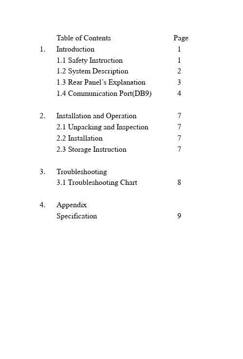
Table of Contents Page 1. Introduction 11.1 Safety Instruction 11.2 System Description 21.3 Rear Panel’s Explanation 31.4 Communication Port(DB9) 42. Installation and Operation 72.1 Unpacking and Inspection 72.2 Installation 72.3 Storage Instruction 73. Troubleshooting3.1 Troubleshooting Chart 84. AppendixSpecification 9Chapter One:Introduction1.1Safety InstructionCaution:The UPS contains voltages which are potentiallyhazardous. All repairs should be performed byqualified service person. The UPS has its owninternal energy source (battery). The outputreceptacles may be live even when the UPS is notconnected to an AC supply.For safe and continuous operation of the UPS depend partially on the care taken by user. Please observe the following precautions.1. Do not disassemble the UPS.2. Do not place the UPS near water or in environmentof excessive humidity.3. Do not allow liquid or any foreign object to getinside the UPS.4. Do not plug appliances, such as hair dryers, intothe UPS receptacles.5. Do not place the UPS under direct sunshine orclose to heat-emitting source.6. The power socket should be installed near theequipment and be easily accessible. To isolatefrom AC input, disconnect the plug in the powercord.7. The printer may best be connected directly to wallreceptacle instead of UPS. (laser printer can’t beconnected to the UPS.)8. The battery will discharge naturally. If it is chargedperiodically, its life time will be prolonged. It willbe damaged if long-term no use, which will not becovered in our warranty.Page 11.2System DescriptionThe UPS equipped with AVR (Auto voltage regulator) Break-down features accepts wide range input windows without using batteries. It is your best choice for LAN and PC.To enable user to start on the UPS without Utility Power, it is also equipped with “cold start function”.Compact size, lighter weight and quiet operation allow for convenient placement in any office or workplace.Key Features:1. AVR (Auto voltage regulator) Break-down2. Wide Range Input V oltage Windows3. Cold Start Function Built4. Green for CPU version only function5. Compatible with DOS/Windows, Novell, NT, Unix, etc.6. Complete Power Protection7. SNMP ReadyPage 21.3Front/R ear Panel’s Explanation (please refer page5)1)Main SwitchIt is used to control the UPS on / off when user want toturn-on/turn-off the UPS by A C-start function. Please push the main s witch button about 5 seconds until buzzer alarm.2) LED Function(a)Line: green LED When utility power is normal.(LED light.)(b)Inv: yellow LED When UPS working in battery mode.(LED light.)(c)Battery low: red LED When UPS battery voltage less than11.0V (LED light.)(d)Short protection: When UPS working over normal range.(about over 125%) All of LED lighted,buzzer alarm continuously.(e)Overload: When UPS working in overload mode. Inv LED andBat LED will light.3) Secondary SwitchThis is to control the on/off of the UPS. (For NON-CPU version only)4) AC InputThis is to be connected with an AC power cord for plugging into the wall receptacle.5) AC Input FuseThis is to disconnect line input to protect outlets from overload orPage 3short-circuit. A spare fuse is also enclos ing in the bracket forpossible replacement purpose.6) Comm PortAn interface PCB with DB9 connector is mounted on the rear panel to provide signals to the computer via optional UPS kit or Novell monitor board. The pin ass ignments of the interface will be illustrated on page5. (This feature jus t for CPU version)7) UPS OutputThis is to be connected to the computer sockets, which will beprotected by the UPS.8) Telephone portThis is to connect the modem plug and the telephone line.Page 4Page 5Page 61.4 Communication Port(DB9)The communication port on the rear panel of the UPS provides a dry contact type.For DOS/Windows’, Novell’s, & Unix’s solutions, you may contact with local distributor for more details.*True RS232 TypeF O R ST A N D A R D C A B L EDB 9-M 594837261DB 9-F 594837261UPS MONITOR PIN DEFINES.1. Pin5: UPS Shutdown Control Phase.2. Pin8: UPS DC/ON Phase.3. Pin1: UPS BATTERY STATUS.Chapter Two: Installation and Operation2.1 Unpacking and InspectionExamine the packing carton for damage. Notify the carrierimmediately of any damage occurs. Retain the packing for future use.2.2 Installation1)Power off your computer.2)Use your computer’s power cord to connect the UPS (inlet)and a verified grounded 3-wire receptacle.3)Plug the UPS power cord to your computer’s inlet.4)Switch on the UPS by pressing the front panel switch.The “Line” LED will l ight on. The UPS is now considered tobe working properly.5)To test backup function, you may disconnect the power cordof the UPS. The “Line” LED of the UPS will extinguish,“Inv” LED light on (or “Line” LED is flickering) and thealarm will beep every 4 seconds.6)Charge the batteries for 10 hours before use. The UPS willrecharge the batteries automatically whenever its power cordis plugged into a wall receptacle. Y ou may use the UPSimmediately without recharging, but the backup time may beless than the rating.※Caution: Do not plug laser printers into the UPS’s outletbecause they may draw too much power.2.3 Storage InstructionFor extended storage in moderate climates, the batteriesshould be charged for 12 hours every 3 months byplugging the power cord into the wall receptacle. Repeatit every 2 months in high temperature locations.Page 7Chapter Three: TroubleshootingThe Troubleshooting chart covers most of the difficulties that you may encounter under normal working condition. Should the UPS fails to operate properly, please proceed the followings before calling for service.1.Is the UPS plugged into an incorrect wall receptacle?2.If A C input voltage out of windows?When calling for service, please offer the following information:1.Model No. and Serial No.2.Date of problem occur.3.Full description of the problem occur, includingcondition happened, environment installed, devicesconnected to the UPS, etc..Page 8Page 9。
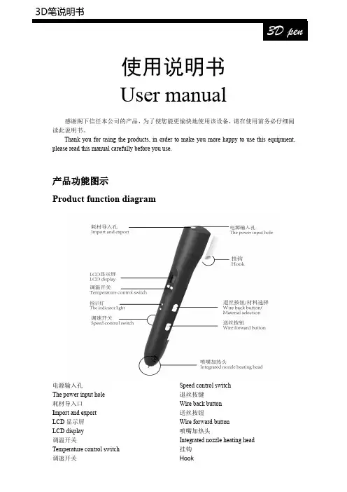
使用说明书Usermanual感谢阁下信任本公司的产品,为了使您能更愉快地使用该设备,请在使用前务必仔细阅读此说明书。
Thank you for using the products,in order to make you more happy to use this equipment,please read this manual carefully before you use.产品功能图示Product function diagram电源输入孔The power input hole耗材导入口Import and exportLCD 显示屏LCD display调温开关Temperature control switch调速开关Speed control switch 退丝按键Wire back button 送丝按钮Wire forward button 喷嘴加热头Integrated nozzle heating head 挂钩Hook规格定义及电气参数Specifications and parameters:出料方式:热熔挤压堆积成型Discharging mode:hot melt extrusion molding 成型方式:三维成型Molding:three-dimensional molding打印范围:无限定Print range:Unlimited吐丝速度:可调Spinning speed:adjustable 温度:60℃-245℃可调T emperature:60℃-245℃adjustable 设备工作电压:12V2AWorking voltage:12V2A equipment喷嘴直径:0.7mmThe nozzle diameter:0.7mm耗材直径:1.75mmFilament diameter:1.75mm特征Characteristic:·LCD屏能显示耗材种类、速度、温度、警告信息LCD display can directly show the information like filament type,speed level,temperature, warning,more humanized display interface.·支持ABS和PLASupport shift between PLA and ABS·2A供电,能耗低Max working current is2A,lower energy consumption·人体工学设计,注重用户感受Human engineering design,Pay attention to the user experience·点触式调速调温,智能切换材料所需温度Smart program control,simplifies use,intelligent filament replacement are used for the first time,this makes the user more convenient,more secure to change and replace the filament.警告!Warning!1.此设备适用于8岁以上儿童和成人使用。

An instruction manualDirectoryFirst,note..................................................................................................... 错误!未定义书签。
1 security matters ....................................................................................... 错误!未定义书签。
1.1 traffic safety first ................................................................................... 错误!未定义书签。
1.2in the hospital should be shut down .................................................. 错误!未定义书签。
1.3on the plane should be shut down..................................................... 错误!未定义书签。
1.4 gas should be shut down.................................................................... 错误!未定义书签。
1.5 in the blasting site near shutdown of................................................. 错误!未定义书签。
2the use of mobile phone......................................................................... 错误!未定义书签。

电子书手册组件部件名称 内部及外部 字符输入键屏幕配置 书籍 音乐 录制 备忘录 日志347第 1 章 入门组件为改进产品性能或质量,组件内容可能会变更,恕不另行通知。
各部件名称部件的外表及所印刷或刻印的内容可随型号或各部件的名称而异。
产品的外部/内部产品的外部/内部字符输入键屏幕配置书籍书籍类型书籍列表当前时间/日期所选的书籍收藏书籍电池阅读进度屏幕配置备忘录备忘录列表所选的备忘录第 2 章 了解基本功能连接 连接耳机 插入/卸下 SD 卡 推荐使用的 SD 卡 连接计算机 将文件(文件夹)复制至产品 删除文件/文件夹 断开与计算机的连接17开机/关机 开机关机使用锁住和重置功能 使用锁住功能使用重置功能选择菜单选择想要的菜单充电 通过连接到电脑充电13141516开机/关机开机1. 将【锁住/电源】开关滑至右端,即可开机。
关机1. 产品开启后,将【锁住/电源开关】滑至右端,即可关闭电源。
使用锁住和重置功能使用锁住功能1. 将【锁住/电源开关】滑至左端,即可锁定该产品。
2. 将【锁住/电源开关】滑至右端,即可对该产品解锁。
使用重置功能1. 若程序暂停且按键不起作用,打开产品底部的护盖,并用带尖端的工具 按【重置孔】。
2. 将【锁住/电源】开关滑至右端,即可开机。
使用重置功能时,当前时间及存储于内存的数据不会删除。
在产品运行过程中切勿使用重置功能。
这可能会对内存造成严重损害。
选择菜单选择想要的菜单由于 EPD 的特征,可能会出现以下情况,但产品仍可正常运行。
- 在菜单间移动时屏幕闪烁且响应缓慢。
- 屏幕可能出现残影。
- 若在极冷或极热的环境下使用,残影现象可能更严重,屏幕切换可能非常缓慢。
(工作温度: 0 ˚C~ 40 ˚C)- 若在明亮的阳光下使用,屏幕上可能出现横线。
(若转移到遮荫处使用,将正常工作。
)连接耳机1. 将耳机连接到耳机端口。
耳机必须另行购买。
插入/卸下 SD 卡1. 关闭电源,将 SD 卡(见下图)放入 SD 卡插槽,并轻轻按紧。
X300Pro3User ManualStatementThis handbook is the manual of X300Pro3.Without the written permission from the manufacturer, any company or individual shall not copy or backup it in any form(electronic,mechanical, photocopying,recording or otherwise).This manual is only operating instructions for X300Pro3.If any result caused by using it on other equipment,the company does not assume any responsibility for it.If not quality problems of X300Pro3such as equipment failure caused by user abuse or misuse, unauthorized disassembly,repair equipment yourself,not operate or maintain by the instructions, lose it,the repair will not be free.Other product names mentioned in this manual are in order to describe how to use X300Pro3,and their copyrights are still observed by the original company.X300Pro3and files are used for normal vehicles maintenance.If used for illegal purposes,the company does not assume legal responsibility.ContentChapter1:Summary (1)1.1Features (1)1.1.1Advantages (1)1.1.2Durability (1)1.2Introduction of the device (2)1.2.1The main unit and accessories (2)1.3Hardware technical specification (3)1.4Functions Setting (3)1.4.1Functions Selection (4)1.4.2System Setting (4)1.4.2.1Language Selection (4)1.4.2.2Contrast Adjustment (5)1.4.2.3Font Setting (5)1.4.2.4Metric/Inch………………………………………………………………………..1.4.2.5Data Logging……………………………………………………………………..1.4.3System Information (5)1.4.4Device Self-test (6)Chapter2:How to update software for X300PRO3 (6)2.1Update Tool software Installation (7)2.2Software Updating (8)Chapter1:Summary1.1.Features1.1.1.AdvantagesMulti-language environment can be applied in different countries and regions.The main unit system adopts ARM high speed chip to keep it running fast,stable and anti-jamming.Updating via SD card at any moment.Modern design and high-definition true color screen realize the integration of automotive industry and electronic information technologies and make auto diagnosis and key programming easier,practical and economical.1.1.2DurabilityIntegrity structure design makes it crack resistance,shock resistance and durable.Industrial design ensures the tool work stably under tough environment, such as high and low temperatures.1.2Introduction of the device1.2.1The main unit and accessories(Picture as below)Name InstructionTesting cable port Connect to the main test cable for autokey programmingDisplay Screen Show informationF1Keyboard input option keyF2Keyboard input option keyEnter OKESC Exit or give upUp UpRight To rightDown DownLeft To leftTF card slot To keep diagnostic program or data1.3Hardware technical specificationDimension:23.9cm(L)*12cm(W)*3.6cm(H)CPU:ARM7Power Supply:DC12VOperation Power:DC12VOperation Temperature:-20~60Display Screen:320*240TFT Screen1.4Functions SettingPower on and then press ENTER on the screen then go to the function setting, setting information as shown below:1.4.1Function SelectionSelect different functions according to different requirements.Note:Software numbers and functions are different according to different product configuration.Further detailed information,please contact your distributor.1.4.2System SettingSelect System Setting,language and contrast can be adjusted,as shown below:1.4.2.1Language SelectionThis device supports simplified Chinese,traditional Chinese,English,Russia,Greek, Spanish,Italian.In the language directory,select required language by Up and Down and press ENTER to confirm it.1.4.2.2ContrastAccording to the environment,adjust the brightness of the screen by the left andright buttons,as shown below:1.4.2.3Font SettingAccording to requirement,select different font.1.4.2.4Metric/InchAccording to different requirements,select the Metric/Inch by the up and down keys, and press ENTER to confirm as show below,1.4.2.5Data LoggingAny problems during testing,please use the Data Logging function to record the test process and send the data to us.Select ON by the up and down keys and press ENTER to confirm,shown as below,Note:Every time you need to select ON if you want to record the data before testing car.1.4.3System InformationSystem information includes product serial number,hardware version,software version,release date,register password,etc.1.4.4Device Self-testDevice self-test includes screen display,keyboard testing.hardware self-testing,etc. If it cannot show enough pictures on the screen,keyboard not work,and hardware self-test not get through,please return this X300Pro3to the manufacturer.Chapter2:How to update software for X300Pro32.1Update Tool software installationDownload the update tool and diagnostic software on ,double click,then go to the next step:Step1Click“Next”Step2:Click“NextStep3:Click“Next”Step4:Click“Finish”2.2Software UpdatingAfter Update Tool installationcompleted,click the Update Toolsoftware icon on desktop to start the update tools.Operation steps asfollowing:Step1Open update toolStep2Click the source menu,choose theprogram you want to update,click it and confirmStep3:Click and select all the software then click“update”Step4:Wait for several minutes then the updating finishedNote For new update software and questions during updating,please contact your distributor.。
User Manual Abbreviations - How to Write Abbreviations are widely used in technical documentation, including user manuals, to simplify and standardize the writing process. They serve as a convenient way of conveying complex terms or phrases in a concise manner. In this user manual, we will provide a comprehensive guide on how to write and use abbreviations effectively.Why Use Abbreviations?Abbreviations are used to enhance readability, reduce word count, and provide a standardized approach to technical writing. By replacing long and repetitive terms with abbreviations, users can quickly grasp the meaning behind the concept without being overwhelmed by lengthy explanations. Additionally, abbreviations facilitate the process of translating documents into different languages, ensuring consistency across various language versions of a user manual.Guidelines for Creating AbbreviationsWhen creating and using abbreviations in user manuals, it is crucial to follow some guidelines to ensure consistency and clarity throughout the document. Here are some key guidelines to consider:1. Create Abbreviations When NecessaryOnly create an abbreviation when it offers a significant advantage in terms of readability and reducing word count. Avoid unnecessary abbreviations, particularly for terms that are already widely known and understood by the target audience.2. Full Term IntroductionIntroduce the full term or phrase before using an abbreviation for the first time in the document. This helps the readers understand the meaning of the abbreviation and ensures clarity.3. Consistency in UsageMaintain consistency in the usage of abbreviations throughout the entire user manual. Always use the same abbreviation for a specific term throughout the document.4. Avoid Acronyms ConfusionDifferentiate between abbreviations and acronyms. An abbreviation is formed by taking the initial letters of a term or phrase, while an acronym is an abbreviationformed from the initial letters of multiple words that can be pronounced as a word. Make sure to clarify the difference between both in the user manual.5. Use Abbreviation ListInclude an abbreviation list at the beginning or end of the user manual. This list will provide users with a quick reference for all the abbreviations used throughout the document.6. Limit the Number of AbbreviationsTo avoid confusion, limit the usage of abbreviations to a necessary minimum. Overuse of abbreviations can lead to comprehension difficulties and make the document harder to read and understand.Writing the AbbreviationWhen introducing the abbreviation for the first time, follow these steps:1.Write the full term or phrase, followed by the abbreviation inparentheses. For example, User Interface (UI).2.Make sure the abbreviation is capitalized if the full term or phrasestarts with capital letters.3.Place a comma after the abbreviation, and continue the text withoutany special formatting.Once the abbreviation has been explained, it can be used consistently throughout the user manual without the need to reiterate the full term or phrase.Using Abbreviations ResponsiblyWhile abbreviations can significantly improve readability and reduce word count, it is essential to use them responsibly. Consider the following points:1.Do not overuse abbreviations, especially in sections that requiredetailed explanations or when addressing novice users.2.Avoid using abbreviations in headings, titles, or section subheadingsto ensure clarity.3.Aim for maximum comprehension by choosing the most suitableabbreviations based on user familiarity and industry standards.ConclusionUsing abbreviations in user manuals is an effective way to enhance clarity, readability, and consistency. Following the guidelines provided in this manual will ensure that your document remains understandable and properly conveys information to the intended audience. Remember to use abbreviations responsibly and sparingly, keeping in mind the needs and knowledge level of your users.。
User Manual - Abbreviation in EnglishIntroductionThe User Manual, also known as the instruction manual, provides vital information on how to use a particular product or service effectively. It serves as a reference guide for users, helping them navigate through various features and functionalities. In this document, we will discuss the importance of abbreviations used in English user manuals and their significance in enhancing communication.Why Use Abbreviations?Abbreviations play a crucial role in user manuals as they provide concise and efficient communication. By condensing lengthy terms or phrases into shorter forms, abbreviations help save space and make the content more readable. Moreover, they facilitate easy comprehension, especially in instances where repeating a certain term multiple times may lead to redundancy and confusion.Consistency in AbbreviationsMaintaining consistency throughout the user manual is essential when using abbreviations. A consistent approach ensures clarity and avoids confusion among users. Here are some guidelines to follow:1.Define abbreviations: Every abbreviation used in the manual shouldbe defined clearly when first introduced. This helps users understand theirmeaning and facilitates better comprehension throughout the document.e standardized abbreviations: If there are standard abbreviationsrecognized within specific industries or fields, it is advisable to adhere to those conventions. This aids in establishing a common language and avoids ambiguity.3.Consistent formatting: Ensure that the formatting of theabbreviations remains consistent throughout the document. This includescapitalization, punctuation, and any additional styling used for emphasis.Abbreviation PlacementAbbreviations should be strategically placed within the user manual to maximize their effectiveness. Here are a few ways to achieve this:1.Headers and titles: Abbreviations can be used in headers and titlesto provide a concise overview of the section’s content. This allows users toquickly scan and locate the information they need.2.Paragraphs and bullet points: Within the body of the manual,abbreviations can be incorporated to condense lengthy explanations orrepetitive terms. This helps keep the content concise and focused.3.Tables and diagrams: When using tables or diagrams to present dataor instructions, abbreviations can be utilized to save space and enhancereadability. However, it is crucial to ensure that their meanings are clearlydefined in the accompanying text.Benefits of Using AbbreviationsUsing abbreviations in user manuals offers several benefits:1.Enhanced readability: Abbreviations help users navigate throughthe manual quickly and easily, by reducing the length and complexity of thecontent. This makes the overall reading experience more efficient and user-friendly.2.Space-saving: By condensing lengthy terms, abbreviations savevaluable space, especially in cases where there are limitations on documentlength or size. This is particularly advantageous in the digital space whereconcise content is preferred.3.Improved user experience: Abbreviations contribute to astreamlined user experience, as they allow users to find information morequickly and efficiently. This can lead to increased satisfaction and a positiveperception of the product or service.ConclusionAbbreviations are a valuable tool in user manuals as they contribute to effective communication, enhanced readability, and a streamlined user experience. By adhering to consistent formatting, defining abbreviations, and strategically placing them throughout the document, the user manual becomes a more concise and user-friendly reference guide. It is important to remember to avoid using excessive abbreviations, as this may lead to confusion. When used appropriately, abbreviations can greatly enhance the overall quality and effectiveness of a user manual.。
说明书英语怎么说在跨国交流和国际贸易中,掌握常用的英语词汇是十分重要的。
其中,“说明书”是一个常见的词汇,在不同场合下需要用英语来表达。
下面是一些常用的翻译和表达方式:er Manual:这是最常用的表达方式,通常用于电子产品、机械设备等使用说明书。
2.Instruction Manual:与User Manual的意思相同,用于指导产品的正确使用方法。
3.Guidebook:作为说明书的同义词,用于提供有关操作、安装或使用某一产品或系统的详细信息。
4.Operating Manual:也可以用作“说明书”,强调指导使用者正确操作设备或执行任务。
5.Handbook:可以指某一特定主题的详细指南,或是一本包含操作步骤、原则和信息的手册。
6.Reference Manual:用于提供必要的参考信息,通常辅助于其他类型的说明书。
7.Owner’s Manual:主要用于指导消费者正确使用产品、维护和保养的手册。
8.Service Manual:主要用于指导技术人员进行维修或服务。
9.Installation Guide:主要指引用户如何正确安装产品或设备。
10.Quick Start Guide:提供简明的指导,让用户快速了解产品的基本操作。
请注意,实际情况可能因企业或行业的不同而有所不同,因此很可能会存在其他类似的表达方式。
值得一提的是,以上的翻译方式仅为一般性表达,实际运用时可能需要根据具体上下文和需求进行调整。
另外,在文档翻译时,确保所使用的术语和词汇准确、一致,并符合所涉及领域的业界规范。
总之,在跨文化沟通和国际贸易中,准确描述产品说明书的英语表达是必不可少的。
通过熟练掌握以上常用的翻译方式,我们能够更好地与国际伙伴合作,并确保交流的准确性和流畅性。
希望本文提供的信息对您有所帮助!。
Denmark E-mail:List of contents1. Warnings, legal information and notes to CE-marking and UL listing (3)2. Application and functionality summary (3)3. Operation of display, push-buttons and LEDs (6)3.1 LEDs (7)3.2 Settings (8)4. Terminal list (10)4.1 Overview of the terminals (10)5. Wiring diagrams (11)5.1 AC input connections (11)5.1.1 Connection diagram (11)6. Commissioning (12)7. Technical data (12)8. Dimensions (15)9. Order specifications (15)Example of an order specification for the CSQ-3 (15)Appendix 1: Setting and parameters for synchronising (16)Settings (16)Guidelines for setting of the CSQ-3 (18)Visual representation of the parameters (18)Page 2 of 21 Tel.: (+45) 9614 9614 • Fax: (+45) 9614 9615 • E-mail: deif@User manual, Check synchroscope CSQ-34189340263K (UK)1. Warnings, legal information and notes to CE-marking and UL listingThis manual gives general guidelines on how to install and operate the CSQ-3. Installing and operating the CSQ-3 implies work with dangerous currents and voltages. Therefore this should only be done by qualified personnel. DEIF A/S takes no responsibility for operation or installation. If there is any doubt about how to install or operate the system on which the CSQ-3 is measuring, the company responsible for the installation or the operation must be contacted.The CSQ-3 is CE-marked with respect to the EMC directive for residential, commercial and light industry plus industrial environment. This covers all environment types where the CSQ-3 can normally be used.The CSQ-3 is CE-marked with respect to the low-voltage directive for up to 600V phase to ground voltage, installation category (overvoltage category) III and pollution degree 2.The CSQ-3 can be delivered with UL listing. Please refer to the section “Technical data” for installation information as required by the UL.The package contains the following items:• Check synchroscope CSQ-3 unit • User manual • Two fixing clamps• A plugable connection (mounted on the unit)• Cable for system status output (only marine version)2. Application and functionality summaryThe CSQ-3 check synchroscope is a microprocessor-based synchronising unit providing measurement of all relevant values for synchronising a generator to a net (busbar). It is used in any kind of installation where manual or semi-automatic synchronising is required.In the CSQ-3 there is a possibility of adjusting the following synchronising requirements: The voltage difference between GEN and BB, the size of the phase window and the length of the synchronising pulse.In addition to that there is an indication of ‘U GEN TOO HIGH’ or ‘U GEN TOO LOW’ (red LEDs), phase difference within the preset window ‘ϕOK’ (yellow LED), and finally synchronising output active, ‘SYNC.’ (green LED).Display/readingThe unit measures the two inputs voltages: Generator (GEN) and busbar (BB), respectively. The phase difference from GEN’s zero-crossing to BB’s zero-crossing is calculated by the processor and is shown on the LED circle, consisting of 36 red LEDs.The red LEDs are only lit one at a time and its position indicates the phase difference between GEN and BB. The lit LED simulates the pointer tip of an analogue pointer instrument. If the LED is lit in the 12 o’clock position, the phase difference is 0 degrees. In the 6 o’clock position, 180 degrees etc. With 36 LEDs the resolution is 10 degrees.The movement of the lit LED’s position indicates the frequency difference between GEN and BB. If the indication is turning clockwise (too fast), the GEN frequency is too high in proportion to the BB frequency. If the indication is turning counter-clockwise, the proportion is inversed. The rate of the motion tells about the frequency difference. The faster the rotation, the bigger the frequency difference, e.g. 1 rotation per second = 1Hz. If the BB frequency is 50Hz and the rotation turns right, the GEN frequency will be 51Hz in this example.If the frequency difference between GEN and BB is becoming too big (>3Hz), the circular motion stops and a LED will be lit at the ‘too fast’ or ‘too slow’ mark, dependent on which direction the GEN frequency has to be adjusted to.Normal synchronisingThe unit automatically calculates the synchronising parameters to check if there is the required space for the synchronising inside the preset phase window. These calculations compare the frequency difference with t R and the size of the phase window. When t R is set to ∞, t d can be set by the user and is then included in the calculations instead of t R.If the Δϕ window is set symmetrically, both underfrequency synchronising and over-frequency synchronising is possible.Under- or overfrequency synchronisingWhen the Δϕ window is set asymmetrically the following functionality is possible:theΔϕ window is set asymmetrically with a higher positive than negative Δϕ Ifvalue, only synchronising with the generator input at lower frequency than the busbar input is possible (underfrequency synchronising).theΔϕ window is set asymmetrically with a lower positive than negative Δϕ Ifvalue, only synchronising with the generator input at higher frequency than the busbar input is possible (overfrequency synchronising).Note:This function is not active with t R set to ∞.Page 4 of 21 Tel.: (+45) 9614 9614 • Fax: (+45) 9614 9615 • E-mail: deif@User manual, Check synchroscope CSQ-34189340263K (UK)Dead bus synchronisingWhen the dead bus function is set, the synchronising relay will be activated and the green LED (SYNC) will be lit, when the busbar voltage is below the dead busbar preset level and the GEN voltage exceeds 80% of nominal value.Please notice that when the voltage on the net has been restored, the CSQ-3 will remain in the dead bus function for a period of 5 seconds.Power up resetThe unit will operate when the GEN voltage exceeds 80% of the nominal value. Below this level no functionality is obtained.μP supervision outputDue to the demands from the classification societies (GL) a special optocoupler output has been added on the marine version.From this output it is possible to supervise the internal microprocessor (μP).If an error is present, the output changes state from a low to a high impedance (open collector output).Page 6 of 21 Tel.: (+45) 9614 9614 • Fax: (+45) 9614 9615 • E-mail: deif@3. Operation of display, push-buttons and LEDsTo get access to the settings, remove the front frame and the front foil.The CSQ-3 can be operated in two different modes: ‘Normal mode’ and ‘setting mode’. Normal mode is used to display measuring values, and setting mode is used to view the settings or change them to the desired functionality.User manual, Check synchroscope CSQ-34189340263K (UK)3.1 LEDsThe CSQ-3 has the following LEDs on the fronts showing different operating information.LEDs on primary front (normal mode):LEDColour Function Circle Red The lit LED in the circle shows the phase difference betweenGEN and BUSBARSYNC. Green All preset sync. parameters are OK, and the output relay isactivatedϕ OKYellow The phase difference between GEN and BUSBAR is within the preset windowU GEN TOO HIGH Red The voltage difference between GEN and BUSBAR is outside the preset range. U GEN is too high U GEN TOO LOW Red The voltage difference between GEN and BUSBAR is outside the preset range. U GEN is too lowLEDs on secondary front (setting mode):LEDColour Function Circle Red Parts of the circle are used as scales for the different settingsΔϕYellow Shows that the Δϕ scale is active t d Yellow Shows that the t d scale is active Please notice that t d only becomes active with t R set to ∞ t RYellow Shows that the t R scale is active ΔUYellow Shows that the ΔU scale is active U bus Yellow Shows that the U bus scale (dead bus) is activeFor further information about the settings, please see appendix 1.3.2 SettingsPage 8 of 21 Tel.: (+45) 9614 9614 • Fax: (+45) 9614 9615 • E-mail: deif@User manual, Check synchroscope CSQ-34189340263K (UK)OperationThe operation occurs via the secondary foil accessible when the primary foil/front frame is removed. The operation occurs by means of 3 push-buttons: Mode (toggle), up arrow (▲) and down arrow (▼).Control of settingsThe mode button is held down for about 2-3 seconds to obtain the setting mode. This is confirmed by the fact that the LED is lit at the ΔU scale and that the setting of the ΔU max. parameter can be read on the matching scale. With ▲ and ▼ the setting can be changed.For every subsequent push on the mode button, a change to the next parameter occurs. These can be read and changed in a corresponding way. When mode is pushed after the last parameter, one returns to normal mode.When leaving the last setting menu, the LED circle ‘rotates’ to indicate that the current setting has been automatically saved.Please notice that the preset window, ΔU and Δϕ, is divided into two separate settings, making asymmetrical setting of this parameter possible.Also please notice that if the settings are changed unintentionally, these are saved when the setting mode is left.Change of Δϕ rangeThe normal range of Δϕ is -20°...-5° and 5°...20° in 1° steps.This can be changed to -40°...-10° and 10°...40° in 2° steps.Step down to the 20° point with the down arrow button. While pressing the down arrow button, press the up arrow button and the scale will change from normal range to the scale 2 x normal range. Press the up arrow button to return to normal range. While pressing the up arrow button, press the down arrow button, and the scale will change from 2 x normal range to normal range. Please notice that the 2 x normal range mode is indicated on the LED circle by activation of 2 LEDs each time Δϕ is changed.Factory settingsWhen the product is delivered from the factory, the following basic settings will be set:ΔU: 5% of ±U BBt R : 0.5 sec. Δϕ: ±10° Dead bus: OFFRestorage of factory settingsActivate the two arrow buttons simultaneously. While doing this hold down the mode button for approximately 5 seconds. Then the LED circle will light up and rotate to indicate that the factory settings have been restored.4. Terminal list4.1 Overview of the terminals5. Wiring diagrams5.1 AC input connectionsWhen ordering the CSQ-3, the correct range of voltage inputs must be specified. They must be connected as shown below (unused terminals are not shown).5.1.1 Connection diagram6. CommissioningBefore commissioning:Check phases for correct voltage and correct phasesequence.Warning:Incorrect voltage may lead to malfunction anddamage of the unit.7. Technical data±2° (electrical degrees)Accuracy:Resolution: 10° (36 LEDs)Settings, range: Δϕ: ±5…20° in 1° steps or±10…40° in 2° stepsΔU: ±1…10% in 1% stepst R : 0…1 sec. in 0.1 sec. steps or ∞t d : 0…1 sec. in 0.1 sec. stepsU bus offset: Off or 4 levels of noise suppressionbus)(deadMax. frequency difference: No limitInput range (U N): 100…127V AC (115V AC) or220…240V AC (230V AC) or380…415V AC (415V AC) or440…480V AC (450V AC)Busbar input: Load: 2kΩ/VGenerator input: (Max. 2VA). Also supply for the unitMax. input voltage: 1.2 x U N, continuouslyAbove 450V: 1.1 x U N, continuously2 x U N for 10 sec.Frequency range: 40…70Hz (supply)Relay contact: 1 SPST-NO-contactRelay contact ratings: Resistive loads: AC1: 8A, 250V AC(Gold plate silver alloy) DC1: 8A, 24V DCInductive loads: AC15: 3A, 250V ACDC13: 3A, 24V DC(UL/cUL: Resistive load only)Mechanical life: 2 x 10⁷Electrical life: 1 x 10⁵ (nominal value)Optocoupler output: System status off = failure NpN optocoupler output Max. 40V, 10mA 2 wires AWG 20 (red/black) 30 mm length (Only in marine version)Temperature:-10…55°C (nominal)-25…70°C (operating) -40…70°C (storage)Temperature drift: Set points:Max. 0.2% of full scale per 10°CGalvanic separation:According to EN/IEC61010-1All input/output groups to ground: 3.75kV Between all input/output groups: 3.75kV Test conditions: 50Hz, 1 min.Climate:HSE, to DIN40040EMC:CE-marked according to EN50081-1/2, EN50082-1/2 and IEC255-3Connections: Max. 2.5 mm 2(single-stranded)Max. 1.5 mm 2(multi-stranded)Materials:All plastic parts are self-extinguishing to UL94 (V0)Protection:Front: IP52. Terminals: IP20According to IEC529 and EN60529Type approval: For current approvals please see (Only valid for marine version)UL listing:On request, the instrument can be delivered according to UL listing:UL508, E230690 T ambmax 50°C For use in a flat surface of type 1 enclosure Wire: 24-12 AWG Use 60/75° C copper conductors only Main disconnect is to be provided by installerTerminal screw torque: 5-7 lb-in.Installed in accordance with the NEC (United States) or the CEC (Canada)CAUTION: Risk of electrical shock. More than onemain disconnect may be required to de-energize equipment before servicing.Dimensions: Please see drawing in section 8 Panel cut-out: 91 x 91 ±1 mmWeight: < 0.40 kgAppendix 1: Setting and parameters for synchronisingSettingsΔUHere the allowed relative voltage difference between GEN and busbar is adjusted. The regulating range is ±1…10% in steps of 1%. The adjustment is made individually for ΔU MIN and ΔU MAX, so asymmetrical adjustment is possible. The setting is done according to the following formula:(U GEN – U BUSBAR) x 100ΔU MIN, ΔU MAX =U BUSBARIf the preset value is exceeded, one of the two U GEN LEDs will emit red light, and synchronising is not possible.If the generator voltage is too low, the U GEN too low LED will be lit.If the generator voltage is too high, the U GEN too high LED will be lit.If both the U GEN LEDs are lit simultaneously, there is an overvoltage error on the input. In this case, disconnect the unit and check the applied voltage level!ΔϕHere the phase window is adjusted, in which synchronising can take place. The adjustment starts from ±5° and the window can open symmetrically or asymmetrically around this value.The regulating range is -20°...-5° and 5°...20°, in 1° steps or-40°...-10° and 10°...40°, in 2° steps.t RHere the length of the pulse for the synchronising relay is adjusted.The regulating range is 0...1 sec. in steps of 0.1 sec. or ∞.This function makes it possible to adjust the synchronising pulse according to the external breakers demands (closing time).For special purposes it is also possible to adjust t R to ∞ (infinite). This setting will (after t d has expired) provide a synchronising pulse as long as the following conditions are met:•Phase is inside the phase window•Voltage > 70% of U NOMINALt dHere the time is adjusted, in which the phase difference must be inside the preset synchronising window to allow SYNC. The regulating range is 0...1 sec. in steps of 0.1 sec.t d is only activated if t R is set to ∞.Dead busThe possibility of closing the circuit breaker even though the busbar voltage is missing. There is an extra adjustment, U BUS, where the level of dead busbar can be set. This facility makes dead bus synchronising possible, even though there is noise on the busbar. The regulating range is off or 10...40% of U N in steps of 10%.Setting Dead bus function U BUSOFF Deactivated10 Activated within the range 15-25% of actual generator voltage > 70%20 Activated within the range 25-30% of actual generator voltage > 70%30 Activated within the range 30-40% of actual generator voltage > 70%40 Activated within the range 40-50% of actual generator voltage > 70% Please notice that this setting is a coarse step regulation for suppression of possible noise on the busbar. The scale 10-20-30-40 should therefore be considered more as a 4 level noise suppression than as an accurate measuring setting.Please notice that when the voltage on the net has been restored, the CSQ-3 will remain in the dead bus function for a period of 5 seconds.Guidelines for setting of the CSQ-3CommissioningNormally t R is adjusted so it equals the circuit breakers closing time and Δϕ-/Δϕ+ to max. allowed synchronising error.Please notice that the CSQ-3 calculates space for t R (breaker closing time) within the chosen Δϕ window at the actual Δf (slip frequency). Therefore the max. synchronising error will never exceed the chosen Δϕ window.Calculation exampleThe breaker closing time is 200mS, and t R is chosen to 200mS. The phase window is set symmetrically to ±10° (electrical degrees). Then the max. Δf can be calculated using the following formula:Synchronising relay pulse will not be emitted if Δf exceeds 0.278Hz.(Δϕ-) + (Δϕ+)Δf = 360 x t R 10 + 10 Δf = = 0.278Hz 360 x 0.2Calculation of the actual synchronising error – not to be mistaken for the max. synchronising error which is solely determined by the chosen Δϕ windowThe next examples apply to situations where t R is set in the range 0.1...1 sec. Example:With a slip frequency (Δf) of 0.1Hz the phase changes with a rate of 36°/sec. If Δϕ is set to ±10° and t R is set to 0.2 sec. = breaker closing time, the actual synchronising error can be calculated.The moment the phase is within the set phase window (Δϕ) the relay of the CSQ-3 is activated on condition that there is space for the chosen t R, in this case 0.2 sec. If Δf is too big it will cause lack of space for the chosen t R time within the chosen Δϕ window. Example 1:With a phase change of 36°/sec. the phase will change 7.2° during the 0.2 sec. This means that we can now calculate the phase displacement at the exact moment when the breaker closes. Δϕ is set to -10° and +10°. The CSQ-3 relay will be activated -10° before top (12 o’clock position), and after 7.2° the breaker closes which means that the breaker closes 10° - 7.2° = 2.8° before top, that is an actual synchronising error of -2.8°. Applying the formula on page 17 the max. Δf with the shown settings can be calculated to be 0.277Hz.Example 2:If we assume that the slip frequency in the actual case is 0.2Hz the phase changes with a rate of 72°/sec. With a phase change of 72°/sec. the phase will change 14.4° during the 0.2 sec. which gives a synchronising error of 10° - 14.4° = -4.4°. The negative result means that the breaker closed 4.4° after top, that is an actual synchronising error of +4.4°.Example 3:The same as examples 1 and 2 but with a slip frequency of 0.3Hz = 108°/sec. At t R = 0.2 sec. the phase will change 21.6°. As the Δϕ window is set to ±10°, the CSQ-3 will calculate that there is no longer space for a t R pulse of 0.2 sec. and therefore no relay pulse is emitted.General formula for the above-mentioned:Actual synchronising error = (Δϕ-) - 360 x Δf x breaker closing time (t R).Alternatively at negative slip frequency:Actual synchronising error = (Δϕ+) - 360 x Δf x breaker closing time (t R).If the result is negative the synchronising will take place after top (0°) provided that there is space for t R within the Δϕ window.If you want to avoid synchronising after top, Δϕ is set asymmetrically. At positive slip frequency (Δf) as in the shown example a setting of Δϕ- to -10° and Δϕ+ to +5° would have as a result that synchronising after top of more than 5° would not be possible.The length of the relay pulse t R can never be set to a lower value than the breakerclosing time, whereas t R can be set to a higher value if you want the max. slip frequency (Δf) to be lower to limit the rush of current of the breaker (the generators) inconnection with the synchronising.Example:In the light of the above-mentioned examples t R is changed to 0.4 sec. With a slip frequency (Δf) of 0.1Hz = 36°/sec. and t R = 0.4 sec. the phase changes 14.4° during the 0.4 sec. If Δϕ is set to ±10° the CSQ-3 will calculate that there is space for t R. Withthis setting the synchronising error will be identical with the synchronising error in example 1 (-2.8°) as the breaker closing time is the same (0.2 sec.). But the max. Δfcan now only be 0.138Hz and not, as in example 1, 0.277Hz. The max. slip frequency (Δf) could also be controlled by setting Δϕ differently. If Δϕ was set to ±5° instead of ±10° the max. Δf would be 0.138Hz at t R = 0.2 sec. With this setting and a Δf of 0.1Hz the actual synchronising error will be +2.2°. Please notice that the breaker now closes2.2° after top and not, as in example 1, 2.8° before top. The choise of setting must bebased on the knowledge of the actual installation in which the CSQ-3 is applied. But the examples are to show that t R and Δϕ are inextricably connected and influence the same parameters, but with different results as to the calculation of the actual synchronising error.If t R is set to infinite (∞) the max. allowable Δf can no longer be controlled by means of t R. When t R is set to infinite the setting of t d is automatically activated. Infinite t R is primarily used where the CSQ-3 is applied as supervision of an automatic synchronising system or in connection with closing of a tie breaker where you want to control frequency, phase and voltage to be within certain values before the breaker is closed.The setting of t d is to be calculated from Δϕ and the estimated max. allowable Δf.(Δϕ-) + (Δϕ+)t d =360 x ΔfExample 1:Δϕ is set to ±7°, and a max. Δf of 0.05Hz at the moment of synchronising is estimated to be allowable.| -7 | +7t d =360 x 0.05t d = 0.77 sec. ~ 0.8 sec.Please notice that when t R is set to infinite (∞) the synchronising pulse (the relay contact of the CSQ-3) is interrupted the moment the phase is outside the set phase window. As the timer t d starts the moment the phase is within the set phase window Δϕ, and is to expire in the period the phase is still within the phase window before the synchronising pulse is emitted, it means in the shown example that with an actual ΔfUser manual, Check synchroscope CSQ-3 of 0.049Hz the synchronising pulse would only be 18 msec. To avoid transmission of such a short synchronising pulse, the CSQ-3 performs a calculation based on Δf and the actual phase window to make room for a synchronising pulse of at least 100 msec. Referring to example 1, 100 msec must be subtracted from the calculated t d to allow a max. Δf of 0.05Hz.Function in particular situations:In connection with test “on desk” the CSQ-3 is normally connected to the same supply point so that frequency and phase are completely identical on the generator input and the busbar input. At this test form the following must be noticed:The first time the CSQ-3 is connected, synchronising pulse is emitted whether the Δϕwindow is set symmetrically or asymmetrically. If only the busbar input is interrupted subsequently (the CSQ-3 is supplied with auxiliary voltage from the generator input), synchronising pulse is only emitted if the interruption has lead to the result that the Δϕwindow was left in connection with the interruption (occurs if the interruption results in a noise pulse).If Δϕ is set asymmetrically so that only e.g. positive Δf is accepted and Δf changes sign (inverse direction) after the phase between generator and busbar is within the phase window, the synchronising pulse is not interrupted until the Δϕ window is left, even if Δf has changed sign to negative Δf.If Δf is changed to correct direction of rotation after the phase is within the phase window the CSQ-3 calculates if there is space for t R (the synchronising pulse), and in that case synchronising pulse is emitted.Errors and changes excepted4189340263K (UK)。