User Manual
- 格式:pdf
- 大小:561.53 KB
- 文档页数:28

User Manual - A Guide to Using Instructions IntroductionThe user manual is a comprehensive guide that provides detailed instructions for using a particular product or service effectively. It is designed to assist users in understanding the features, functions, and operation of the product, thus enabling them to make the most of it. This document serves as a guide to understanding and utilizing user manuals effectively.Importance of User ManualsUser manuals play a crucial role in facilitating the use of a product. They provide step-by-step instructions, troubleshooting guidance, and necessary information about safety precautions. User manuals act as a bridge between the user and the product, allowing the user to navigate through its functionalities efficiently. They enhance user experience by offering solutions to common issues and offering tips for optimized usage.Structure of User ManualsUser manuals typically have a standardized structure to ensure clarity and ease of use. The following sections are commonly found in user manuals:1.Introduction: This section provides an overview of the product,highlighting its features and benefits. It sets the tone for the user manual and creates interest in the product.2.Safety Information: This section emphasizes safety precautions forusing the product. It includes warnings, cautions, and instructions to ensure the user’s safety during operation.3.Getting Started: In this section, users are guided through the initialsetup and installation process. It includes information about essentialrequirements and the first steps to take when starting to use the product.4.Product Operation: This section provides detailed instructions onhow to operate the product. It explains the functions of various buttons,controls, and settings, allowing users to perform specific tasks with ease.5.Troubleshooting: When users encounter issues or errors, thissection provides step-by-step guidance to diagnose and resolve commonproblems. It is essential for users to refer to this section before seeking further support.6.Maintenance and Care: Proper maintenance helps optimize thelifespan and performance of the product. This section outlines maintenancetasks, cleaning procedures, and any additional care requirements.7.Frequently Asked Questions: Compiled from the most commoninquiries, this section addresses specific queries that users may encounterduring product usage. It provides quick solutions to avoid unnecessary support requests.8.Contact Information: Finally, user manuals include contact detailsfor customer support, including phone numbers, email addresses, and online forums. This information acts as a resource for users experiencing complexissues or requiring additional assistance.Tips for Using User Manuals EffectivelyTo make the most of a user manual, consider the following tips:1.Read the Manual: Thoroughly read the user manual before operatingthe product for the first time. This will familiarize you with its features,capabilities, and safety instructions.2.Follow Step-by-Step: Go through the instructions systematically,following each step carefully. Skipping or overlooking steps may lead todifficulties or even damage the product.3.Highlight Important Information: Use highlighters or sticky notes tomark critical instructions, warnings, or troubleshooting solutions. This willallow for easy reference in the future.4.Consult Troubleshooting: When facing issues, refer to thetroubleshooting section before seeking external support. Often, minor issues can be resolved independently with the help of the manual.5.Keep the User Manual Handy: It is advisable to keep the usermanual in a safe place where it is easily accessible. This ensures that it isreadily available whenever required, even after an extended period of usage.6.Update the Manual: In case of any updates or revisions to theproduct, check the manufacturer’s website for the latest version of the usermanual. Keeping up-to-date ensures that you have the most accurateinformation regarding the product.ConclusionUser manuals are indispensable tools for understanding and operating products effectively. By following the instructions provided, users can maximize the benefitsand avoid potential issues. Remember, a well-utilized user manual enhances product experience and promotes user satisfaction.。

ShineMaster User ManualSHENZHEN ATESS POWER TECHNOLOGY CO.,LTDNo.28 Guangming Road, Shiyan Street, Bao’an District,Shenzhen, P.R.ChinaAbout the user manual1.1 Manual description 1.2 Copyright statement 1.3 Applicable personnel 1.4 Manual use3.1 ShineMaster installationenvironment3.2 ShineMaster installation method 3.3 Connect to the photovoltaic deviceInstallation and ConnectionCONTENTShineMaster built-in page parameter setting2.1 Device Overview 2.2 Unpacking2.3 ShineMaster Network IntroductionProduct description123 4 4.1 ShineMaster IP address query4.2 ShineMaster built-in page access 4.3 ShineMaster Status View4.4 ShineMaster Datalogger managing 4.5 Baud Rate Setting4.6 Server Address and Shine Master IP settingServer: Shineserver’s operation5.1 Registration and login 5.2 View monitoring data5.3 Add or Delete Monitoring devices, change the ShineMaster Baud rate7.1 ShineMaster specificationTechnical specificationsContact us6.1 Common faults and troubleshooting 6.2 MaintenanceDevice Maintenance56781 About the user manual1.1 Manual description1.4 Manual usagePlease read this manual carefully before using ShineMaster. At the same time, please keep this manual in a safe place so that operators and maintenance personnel can find out. The contents of the manual will be continuously updated and corrected. It is inevitable that there will be slight inaccuracies or errors in the actual contents. Users should refer to the actual product purchased. The latest user manuals can be downloaded from , and can also be obtained through ATESS's sales or service channels.1.2 Copyright statement1.3 Applicable personnelDear users, thank you very much for using the ShineMaster data logger (hereinafter referred to as ShineMaster) developed and produced by Shenzhen ATESSPowerTechnologyCo.,Ltd. (hereinafter referred to as ATESS). We sincerely hope that this product will meet your needs and expect you give more opinions on theperformance and function of the product. The purpose of this manual is to provideusers with detailed product information and instructions for installation, operation, and maintenance.The version of this manual is V1.1. ATESS owns the final interpretation right of this user manual. If there is any change in product parameters, appearance, packaging, etc., the latest information of the company shall prevail without notice.This user manual is copyrighted by ATESS. Any unit or individual may not excerpt or copy part or all of this user's manual without the written permission of the company. It may not be transmitted in any form, including materials and publications. Infringement must be investigated.This manual is for professional technicians who install, commission, and maintain the ShineMaster and for users who perform daily operations. This manual does notinclude electrical connections for inverters, combiner boxes, weather stations, smart meters, and anti-reflux devices, as well as related precautions. If necessary, refer toATESS's corresponding user manual or instruction.Product description 22.1 Device OverviewFig.2-12.1.1 InterfaceThe interface of ShineMaster, as shown in figure 2-1 above.The functional description of each interface is shown in table 2-1.Item Name FunctionA POWER Power supply portB KEY Reset button (temporarily unavailable)C LANRj45 port:Connect Shine ShineMaster to thelocal network area of Shine Server through RJ45D RS-485Two-way RS485 interface2.1.2 Indicator LedShineMaster is equipped with seven LED indicators. The status of the ShineMaster can be displayed by the LED indicator. As shown in figure 2-1 and table 2-2 above.Table 2-1Item Name FunctionGPower LEDPower indicator light, constant on means powersupply is normal H Network LED2: flashing means connecting to the server;3:on means connection to the server Network light:1: off means fail to obtain IP address;I Device LEDThe number of the LED continuously flashing means the device number connected to the ShineMasterJConfigurationLED Flashing when configuration , if successful , the LEDwill be off (temporarily unavailable )K RF RF signal indicator (temporarily unavailable )L WiFi WiFi signal indicator (temporarily unavailable )M 2G/4G 2G/4G signal indicator (temporarily unavailable )table 2-22.2 Unpacking 2.2.1 Packing ListShineMaster and accessories can be found as below figure 2-2:Fig 2-2Item Name Amount AShineMaster1 pcsB5V power adapter 1 pcs C Terminal RS485 1 pcs D Wall plastic column 4 pcs EM3.5*20 screw 4 pcs F ShineMaster user manual1 pcs GEthernet cable1 pcsTable 2-4AB CD E F G2.2.2 Serial No. and Check CodeThe ShineMaster serial No. (S/N ) and check code (C/C )is ticked on the ShineMaster’s package box, which have 10 digits mixed up with letters and numbers. the serial No. and check code for each device are unique, to identify each ShineMaster. When you want to upload the data of ShineMaster to the server, you need the serial No. and ‘check code’ corresponding to register on the serverNote: The precondition of local access is that the address of PC and ShineMaster must be in the same domain, thereby building up a local monitoring system.ShineMaster supports network communication, which can be communicated via wired WLAN. Upload the monitored data to the server of ATESS, and then access the server's domain name. Realize industrial common communication mode RS485, also supports wired communication ways to monitor and set slave devices and perform online upgrades on devices. By accessing ShineMaster's internal IP address, you can enter the built-in page for parameter setting and device addition viewing (please refer to section 4.4 below).ShineMaster monitors the photovoltaic devices through RS485. The diagram below shows the schematic diagram of network monitoring through wired RS485.Fig 2-52.3 ShineMaster Network IntroductionShineMaster3.3.1 RS485 cable connection3 Installation and Connection3.1 ShineMaster installation(2) Cable RS485 in maximum 500m.The installation environment of ShineMaster and communication with other devices:(1) Indoor installation, temperature - 40 ~ 60℃ , avoid moisture and direct sunlight.3.2 ShineMaster installation 3.2.1 Installation Procedure(2) Connect cables between RS485 interface and RS485 interface on ShineMaster (please refer to 3.3.1 below for details)(1) Install ShineMaster on a vertical plane or horizontal plane.The installation steps are as follows :(3) Connect the network cable (insert the network line into the LAN interface on ShineMaster).(4) Connect the Power supply (connect the power cord to the Power interface on ShineMaster).3.3 Connect to the photovoltaic deviceShineMaster can communicate with the inverter, weather station, smart meter, combiner box and other photovoltaic devices to achieve the purpose of data collection.1.ShineMaster (master) communicates with slave devices via RS485 wiredconnection. 485A+ on the RS485 port of the slave device corresponds to A1+ or A2+ on the ShineMaster 485 port, 485B- and ShineMaster 485 on the RS485 port of the slave device. Corresponding to B1- or B2-. The following is a schematic diagram of the connection between the ShineMaster and the inverter:Note: the RS485 shielded wire must be ground (PE) for long distance communication, so as not to affect the communication stability.Fig 4-12. Note that the inverter also has an interface like the one below :3.The inverters are connected to the ShineMaster via RS485 serial connection. Using the RS485 wired communication connection, the ShineMaster can monitor up to 32 inverters stably.Note: The weather station, combiner, and smart meter manufacturers must be designated by ATESS, otherwise monitoring will not be possible.4.The ways of ShineMaster connection to Smart meter, combiner box andenvironmental monitor are similar to the connection of inverters. The weather station can be connected to the inverter in series, and the communication line of the smart meter can be directly connected to the ShineMaster RS485 port.4 ShineMaster Internal Page4.1 ShineMaster IP address query1. Connect the PC computer and the ShineMaster LAN port to the network port of the router through the network cable so that they are in the same LAN.3. Enter the ShineMaster IP address in the browser to enter the ShineMaster internal2. Go to the router's management page and check the "Internet host list" to query the IP address of the ShineMaster IP address with the serial number of the ShineMaster as the device name. This IP address is the IP address assigned by the router to theShineMaster. If you do not know how to do this, contact your network administrator to perform the operation.Note: The router needs to enable automatic IP assignment, that is, open the DHCP function4.2 ShineMaster built-in page access1.If the user successfully access the ShineMaster internal page, you can directly enter the built-in page login interface, as shown in Figure 4-1Before accessing, check whether the communication cable between the devices is securely connected.then you can enter the ShineMaster IP address in the IE browser to access the built-in page of ShineMaster. As long as the ShineMaster is on the same domain as the computer you are accessing, you can access the Shine WebBox built-in server.2.Enter the user name and password, the default login user name: admin password: admin, fill in and click on login to enter the ATESS ShineMaster system page.(3) In the third drop-down list, fill in the communication address of monitored device (4) Select "Add" and click Save.(5) After successfully saving, enter the "Device Status" page to confirm whether the device is added successfully.4.4.2 Remove device(3) Fill in the PV device communication address in the third drop-down list.(1) Select the monitoring method for monitoring PV devices in the first drop-down list of "Add or Remove Devices".(2) In the second drop-down list, select the type of PV plant being monitored.(4) Select "Del" and click Save to finish removing of the device.(5) After successfully saving, enter the "Device Status" page to confirm whether the device is successfully deleted.As shown in the picture:4.3 ShineMaster Status ViewClick the ShineMaster datalogger Status to view information such as the “System Status Information”, “Serial Number”, “Server Address”, “Number of Connected Devices”,etc. of the ShineMaster4.4 ShineMaster Datalogger managingDevices should be added in ‘ShineMaster datalogger setting’ interface in internal page prior to monitoring 4.4.1 Add device(1) Before ShineMaster monitors photovoltaic equipment, it is necessary to enter the “ShineMaster Data Collector Settings” page of the built-in page to add devices.(2) In the second drop-down list, select the type of monitored deviceDevice types parameter information:INVERTER: ATESS Inverter;SDM630: three phase meter;BatterBox: battery Box;SDM120: single phase meter;Surveymeter: Survey Meter.1. When you need delete a device, all the options should be the same with themomemet you add this device like: 485 channel, device type, address, if you are not sure about this you can check the device status first.2. When one address is occupied, you cannot just paste the new device, you have to delete the old device and use this address.Add and delete device:4.5 Baud Rate SettingThe Default two channels’ Baud Rate are both 9600, you can adjust the Baud Rate for different scenarios.(2) Choose the corresponding chanels RS485_1 or RS485_2.Set the Baud rate to 9600 as RS485_1(1) Choose the Baud rate at the “Baud rate setting ”Bar.4.6 Server Address and Shine Master IP setting 4.6.1 Data logger IP Setting(1) ShineMaster’s Default setting of the DHCP function is “ON” it will automatically get IP address.ShineMaster(2) If you need a fixed IP address you need following steps(2.1) Turn off the “Dynamic IP” to shut down the DHCP function(2.2) Put in the fixed IP, network management, net mask and DNS then click “Save”4.6.2 Server Address SettingThe Server Address will choose two methods, one is IP and one is domain name, you can only use one at a time.(1) When you are using Server IP to connect the server please turn off the “domainname analysis function”, set the server as 120.77.127.135.1617(2) when you are using the domain name to connect server you can choose on at “Domain Name Analysis Function” set the server as Server port name and data upgrade interval are fixed cannot be changed1 If you add a device, after saving there is no refreshment, please disconnect the data logger and restart it.Caustion:5 Server: Shineserver’s operation5.1Registration and login(1) Enter the address of the server on the computer browser to enter the ShineServer login page. If you are logging in for the first time, register the user name first. Enter the domain name access page, as shown in Figure 5-1.The overseas user server domain name is: 1819set up parameters by the server, you need to first add datalogger to the server, when Shinemaster added to the server, if the subsequent need to modify some parameters of If needed to the datalogger and all monitoring devices for data display, monitoring, andThe datalogger or enable, disable a function can be done through the server.Figure 5-1 Shine Server login page(2) Register the user name and input the user information according to the pop-up. After the information is completed, click “Register”.Note: “ShineMaster serial number” and “datalogger check code” seen on the package box.Fig 5-25.2 View monitoring data(1) After the registration is completed, it will automatically jump to the ShineServer main interface. Click "plant" → "plant data" , and the displayed information is the total power chart of the plant on the day. The drop-down list “Select collector” can be used to view the daily power chart of a single inverter in the power station.2021Fig 5-3(2) Click "plant" → "Device list" to see real-time data monitored by datalogger, "Inverter", "Weather station", "Smart Meter", and "Combined Box" "MAX" .22235.3 Add or Delete Monitoring devices, change the ShineMaster Baud rate5.3.1 Add or Delete Monitoring device(1) In the Server page click the “Device Management” and then click “Data Logger”. In this page click set the device updating icon.(2) Add one device, add one ATESS inverter set the 485 communication address is 1.(3) Delete one device, just like following figure.(4) Above adding or deleting devices if success following figure will pop out.5.3.2 Change ShineMaster Baud rate.(1) In the Server page click “Device Management” then click “Data Logger”, click the Baud rate setting icon.(2) Set chosen channel’s baud rate.(3) If success following figure will pop out.Note: The second channel of Baud rate setting would be the same as the fist channel. 2425ATESS inverterATESS inverter6 Device Maintenance6.2 Common faults and troubleshootingFaultCauseSuggestionCannot enter the ShineMaster internal page ShineMaster can not obtain the IP2.PC and the ShineMaster must be in 1.Enable Router DHCP Functionthe same domain.ShineMaster built-in page "System Status Information" shows not connectedUnable to connect to serverThe international user server domain is .1.Check whether the router network is connected to the Internet.2.Check if the "server address" is correctShineMaster is online, but the monitored device is disconnected after logging in to the accountequipment addressbuilt-in page to equipment address failed2.No access to the3.Inconsistent Photovoltaic1.Monitor connection add equipment and added4.Illegal PV device serial numberthe monitored PV equipment is 103.On the "Device Status" page of the illegal characters.letters and numbers, and there are no 1.Check the communication line is in contact with the stabilitysettings" to add photovoltaic devices device's communication address is 4.Check whether the serial number of built-in page, check whether the 2.Enter the built-in page "datalogger consistent with the added device. digits. It can only contain EnglishLong time no refresh interface after operationConfiguration page does not respondRefresh the page or login in again.6.3 Maintenance1. Avoid frequent switching of power supply, gently handle, to prevent damage;2. ShineMaster is a product for indoor use. Do not place ShineMaster in a humid environment or in direct sunlight.6.1 Reset ShineMasterIf you press the “reset” button for five seconds, it will erase all the registered device information. All the information for the server communication part will be kept.General specification7 Technical specifications7.1 ShineMaster specificationLength * width * height130mm*84mm*25mmNet Weight 180±g Protection gradeIP30Operating environmentAmbient temperature -40℃~ +60℃InstallationIndoor26278 Contact usCommunicationWireline communicationRS485 maximum stability monitoring 32invertersWirerless communicationNot supported temporarilyRS485 communication distance500 meters maximum (twisted shieldedcable)28SHENZHEN ATESS POWER TECHNOLOGY CO.,LTDNo.28 Guangming Road, Shiyan Street, Bao’an District, Shenzhen, P.R.China。

珐玛通盾构机土仓可视化系统用户手册目录1.产品介绍 (3)1.1产品功能及应用场景 (3)1.2 特点说明 (4)1.3 技术参数 (5)2.安装 (5)2.1安装方式 (5)2. 2控制器通信协议 (8)3. 操作 (9)3.1供电 (9)3.2解码器连接说明 (10)3.3摄像机清洗说明 (13)4. 摄像机拆卸说明 (13)5. 安装验收单 (15)1. 产品介绍1.1产品功能及应用场景及时发现刀盘结泥饼众所周知,盾构机刀盘结泥饼对盾构机的开挖效率影响巨大,以往,发现盾构刀盘是否结泥饼的的观测方式多为间接法,通过推进参数的变化,渣土温度的变化来判断刀盘是否结泥饼,该方式主要依靠操作手的主观判断和责任心,容易造成误判,并且发现时刀盘已经结泥饼,处理难度较大。
“珐玛通”土仓可视化系统,可以直观的实时监测土仓内渣土的流动性,渣土的改良效果,帮助操作手提前预判渣土改良参数,大大降低了盾构机刀盘结泥饼的风险。
避免下图情况发生。
及时发现土仓异物受限于勘探间距,盾构施工中异物、孤石等侵入开挖面的情况屡见不鲜,以往,仅能通过开仓勘验的方式进行检查,开仓对地层的稳定性要求较高,部分地层不具备开仓条件,或者需要进行加固后方具备开仓条件,开仓成本较高。
“珐玛通”土仓可视化系统,可以实时监测土仓内的情况,为操作手和施工管理提供第一手的视频资料。
另外,“珐玛通”土仓可视化系统可应用以往需要人工清洁的螺旋机出土口摄像机、皮带卸料口摄像机等恶劣工况的图像监控需求,采用“珐玛通”自清洁摄像系统,可以减少井下工人的工作量,并降低施工风险,尤其是螺旋机出土口摄像机,由于安装位置限制,采用人工清洁的安全风险较大。
本系统也可应用于泥水平衡式盾构机泥水仓液位的直观观测。
更多应用需求欢迎来电咨询。
1.2 特点说明“珐玛通”土仓可视化监控系统针对土仓内恶劣的泥沙环境及砂石冲击进行了优化设计。
安装加工方便,特别针对旧设备推出人仓通道门安装方案,避免了切割加工前盾的复杂工作。


微软用户[选取日期]前言非常感谢您选择了力高新能EK-FT-11电动汽车电池管理系统(BMS: Battery Management System),为了使您能够更好地安装、使用和维护本产品,请在安装和使用前仔细阅读本用户手册(以下简称手册)。
EK-FT-11是力高新能针对电动汽车发展需求开发的新一代电池管理系统。
根据大型电动车的强干扰、高电压、高稳定的需求特点,EK-FT-11的设计具有极强的适用性。
根据组件的不同选择及配置,可满足客户各种不同应用需求,提供优异的产品性能。
EK-FT-11通过有效的隔离及设计方式可较好的屏蔽电动车上较强的电磁干扰,通过汽车级处理器芯片、CAN总线通信方式及高冗余度性的硬件及软件设计,显著提高了系统的安全性、稳定性、可靠性。
1.1 提示本手册包含客户必须掌握的重要信息,如客户未严格按照本手册安装、使用和维护本产品,本公司将不承担相关后果或责任。
1.2 企业资质及相关认证1.3 声明为求准确,本手册已经过复审和验证。
本手册包含的指导和描述对EK-FT-11电池管理系统是准确的,但是由于技术的改进,后续的EK-FT-11电池管理系统及手册可能变动。
EK-FT-11产品突出优势⏹高准确率——采用独有Vmin-EKF 算法(业界最精确的SOC 的估计算法),电池剩余容量估计SOC 精度已达到95%以上,业界领先;⏹高精确度——基于独有的D-Filter 算法高精度采集系统,系统参数(如单体电压)采集误差均在0.2%以内;温度采样误差±1℃(-20℃~85℃),电流采样误差±1A ;⏹高安全性——双重隔离电路及主动保护技术、强电安全、电磁兼容设计、多重主动保护技术(全面的安全管理和控制系统);⏹高效均衡——领先的高频开关电路与温度保护技术(电池智能均衡技术)的使用,可同时控制多路电池均衡,总均衡电流可达到1A ,并通过温度监控、均衡失效等多重保护,确保均衡电路的稳定可靠;⏹强可靠性——创新优化结构设计;系统电路采用高冗余度设计,同时支持CAN 总线和高压继电器两种充放电控制方式;通过EMC 测试、高低温老化、防水防尘以及振动实验等,保证系统可靠运行;采用多重电源隔离方案,使得系统采样和通信的可靠性大大提高;BMUBMUBMUBMUBCU仪表Batterymodule 1Battery module 2Battery module 3Battery module nB U S电机控制器整车控制器⏹CAN 总线通讯功能——可通过多重隔离的CAN 总线实现与整车控制器/电机控制器、仪表及充电机之间的智能交互,实现各种信息的有效共享;EK-FT-11电池管理系统用户手册⏹绝缘监控功能——绝缘检测模块能够有效地检测电动汽车绝缘状况,实时显示绝缘故障等级,确保人身安全;⏹实时显示——通过RS485/CAN接口与上位机或显示屏进行通讯,实时显示电池组电压、温度、SOC、故障等信息;⏹强电控制——将强电控制系统和电池串管理单元独立设计,实现强弱电的有效隔离,避免串扰,提高电磁抗干扰能力,保证系统安全可靠运行;⏹系统上电自检——系统上电后对电压、温度、通讯、显示等功能进行自动检测,保证系统自身的工作正常。

USER MANUAL 嵌入式电源模块用户手册COMPACT SYSTEMAD-2U220S2430嵌入式通信电源模块——用户手册1前言欢迎您使用由本公司研发生产的嵌入式电源模块,模块为一体化设计,整机性能稳定,实用性强。
声明1. 规格书详细描述了嵌入式电源模块的各项性能,在对电源模块进行各项操作前,请用户仔细阅读本规格书,遵守相关行业的安全规范。
对于操作不当或者超出本规格书规定之使用条件导致产品损坏,本公司概不负责。
2. 我公司有权利在不通知客户的情况下更改手册的内容。
安全守则高压 交流引入线为高压工作线路,操作过程一定要确保交流输入断电,操作过程中对不许动用的开关要加上临时禁止标识牌。
注意 交流线路端子接点及其它不必要的裸露之处,要充分绝缘。
注意 上电之前必须接地。
严禁在雷雨天气下进行高压、交流电操作——用户手册2——用户手册4COMPACT SYSTEMAD-2U220S2430嵌入式通信电源模块——用户手册5七、其他特性项目 指标要求性能 机器噪音 输入电压和输出电压电流范围内,距离电源前、后、左、右1米,距离上、下1.5米,电源的噪音应小于55dB(A) 通过 MTBF 100,000H通过 振动 5~9Hz ,振幅3.5mm ,9~200 Hz ,加速度10m/s2,3轴向,每个方向扫频振动5次(3*50分钟),电源不损坏。
通过 冲击 半正弦波,加速度为20G ,脉冲宽度为11ms ,X 、Y 、Z 三方向,各三次 通过 防尘 有一定的防尘功能 通过 气味无异味或有害性气体通过第三章 外形图及接口定义、告警指示一、整机外形图整机尺寸:深(290mm )*宽(482.6mm )*高(89mm )二、安装尺寸图COMPACT SYSTEMAD-2U220S2430嵌入式通信电源模块——用户手册6DISPLAY输出显示电源开关Power高频开关电源High frequency switching power supply并机信号及接点直 流 输 出 DC OUTPUT1路2路交流输入 C OUTPUT电 池 输 入 +电 池 输 入 - 直 流 输 出 +直 流 输 出 -后视图三、端子接口定义浮充:可旋转调节 均充:可旋转调节 Fail:故障时亮 Run:运行正常亮LED 显示 切换开关 拔码开关:均浮充转换 总开关COMPACT SYSTEMAD-2U220S2430嵌入式通信电源模块——用户手册7交流输入(L 、N 、E ) 干结点输出 负载输出保险空开 电池(+)电池(-)负载(+)负载(-)温馨提示 接线方式:可将电源输出正极(红色接线柱)接通信设备如交换机、光端机等GND 地线,电源输出负极(黑色接线柱)接通信设备负极。

AHRS模組USER MANUALARM ® Cortex ®-M 32-bit MicrocontrollerNuMicro ®Family AHRS 模組 User ManualThe information described in this document is the exclusive intellectual property ofNuvoton Technology Corporation and shall not be reproduced without permission from Nuvoton.Nuvoton is providing this document only for reference purposes of NuMicro microcontroller based systemdesign. Nuvoton assumes no responsibility for errors or omissions.All data and specifications are subject to change without notice.For additional information or questions, please contact: Nuvoton Technology Corporation.AHRS模組 USER MANUAL 目錄1簡介 (5)特色 (5)1.1新唐姿態運算優勢 (6)1.22AHRS 模組硬體介紹 (7)模組分類 (7)2.12.1.1主控模組 (8)2.1.2通信模組 (11)3如何使用 AHRS 模組 (14)支援 IDE (14)3.1安裝 Nu-Link Mini 驅動程式 (14)3.2下載 AHRS 模組原始碼 (16)3.3連接 Nu-Link Mini (17)3.4在 Keil uVision® IDE 使用 Nu-Link Mini (18)3.54AHRS 模組資料運算庫 (20)姿態運算庫框圖 (21)4.1姿態運算庫應用架構 (22)4.2AHRS 模塊架構 (23)4.3AHRS 模塊應用框圖 (24)4.45AHRS 模組 Quick START (25)連接至 PC 主機 (25)5.1尋找藍牙模組 (25)5.2使用 AHRS AP 觀看姿態 (27)5.36AHRS 模組電路圖 (30)主控端感測器電路圖 (30)6.1主控端控制單元電路圖 (31)6.2通訊端充電電路圖 (32)6.3通訊端電源及通訊電路圖 (33)6.4AHRS 模組主控端 PCB 佈局 (34)6.5AHRS 模組 USER MANUALAHRS 模組通信端 PCB 佈局 (36)6.67 REVISION HISTORY (38)AHRS模組 USER MANUAL 圖目錄Figure 1-1 AHRS 模組 (5)Figure 2-1 AHRS 模組主控及通訊板全圖 (7)Figure 2-2 AHRS 模組主控端功能介紹圖 (8)Figure 2-3 AHRS 模組通信端藍牙與 USB 接口 (11)Figure 2-4 AHRS 模組通信端功能介紹圖 (12)Figure 3-1 Nu-Link Mini 連接示意圖 (17)Figure 4-1 姿態運算庫框圖 (21)Figure 4-2 姿態運算庫應用於無人機架構 (22)Figure 4-3 AHRS 資料庫模塊 (23)Figure 4-4 應用端框圖 (24)Figure 5-1 搜尋 ITON DM 字樣的藍牙模組 (25)Figure 5-2 與 ITON DM 配對成功 (26)Figure 5-3 Bluetooth 連結的標準序列埠 (26)Figure 5-4 AHRS 模組的初始資料 (27)Figure 5-5 AHRS AP 開啟位置 (28)Figure 5-6 AHRS AP 成功連結 (28)Figure 5-7 長方體方塊展現裝置目前姿態的狀況 (29)Figure 6-1 主控端感測器電路圖 (30)Figure 6-2 主控端控制單元電路圖 (31)Figure 6-3 通訊端充電電路圖 (32)Figure 6-4 通訊端電源及通訊電路圖 (33)Figure 6-5 AHRS 模組主控端正面 PCB 佈局 (34)Figure 6-6 AHRS 模組主控端反面 PCB 佈局 (35)Figure 6-7 AHRS 模組通信端正面 PCB 佈局 (36)Figure 6-8 AHRS 模組通信端反面 PCB 佈局 (37)AHRS 模組 USER MANUAL1 簡介AHRS (Attitude Heading Reference System) 模組姿態方向參考系統模組,搭載著新唐 NuMicro ®M452 系列 MCU ,內有強大的浮點運算單元,且擁有新唐獨家研發的姿態運算庫 (AHRS library),是一種融合各種感測器且計算輸出尤拉角或是四元數,可給予後端開發輕鬆的獲取目前的姿態方向,可應用於無人機、VR 眼鏡、體感控制器、機器人、掃地機、相機雲台…等等;感測器有加速度計、陀螺儀、電子羅盤及高度計…等,模組上又整合了藍牙模組,可與手機或是電腦平台通訊,對於物聯網應用的開發者而言,可以帶來極大的便利性。

User ManualCONTENTSIntroduction (1)Box items and guidelines (2)Charging (2)Unpacking (3)Warning (3)The main parts of the Cashmaster (4)Keys and displayThekeypad (5)Thescreen (5)Thetray (5)Key identificationFastkeys (6)Getting started (7)What you can count (7)Switchingon (8)Setting date and time (9)Setting bank mode (10)Switching bank mode on/off (11)Switching auto-add on/off (12)Switching scroll on/off (13)Counting (14)Learning - bills only (14)Counting loose bills (15)Counting loose coins (16)Counting rolled coins (17)Totalling, clearing, and printing (18)Troubleshooting (19)FAQ (20)Technical specification (20)Global support (21)Copyright © 2017 Cashmaster International. All rights reserved. This document may not be copiedor reproduced in whole or in part, or transferred to any other media or language, by means withoutINTRODUCTIONThe Cashmaster Sigma 105 is an electronic weighing device which calculates the value of coins and bills. The Cashmaster Sigma 105 supports your domestic currency: bills and coins. The intuitive user friendly interface guides you through the cash counting process. The Cashmaster Sigma 105 is programmed to count the contents of a typical cash register:· Bills (loose)· Coins (loose, rolled)Using the Cashmaster you will notice some changes in the way you work:· Reduced paperwork· Streamlined working methods, makingthe business more competitive· More time to concentrate on key tasksChargingCharging takes approximately 3 hours.Only use the device with the factory supplied power adapter.When the LED is red this indicates that the battery is fast-charging. When the LED is green the battery is fully charged.When the LED is flashing the battery is very low and the unit is on slow charge.If the LED continues to flash for more than 3 hours the battery may have a fault (In event of this, switch off the power at the mains and contact Customer Support).To fully charge the battery, plug the Cashmaster machine into the mains. The LED on the front will show GREEN (for one second) then RED .Cashmaster Sigma 105BOX ITEMS & GUIDELINES1. Unpack your Cashmaster machine and check that you have a Cashmaster scale, a tray, a power adapter and a scoop.2. Place the Cashmaster scale on a firm even surface.3. Fit the tray into the top of the Cashmaster scale. Push down very firmly until it clicks into place. (To remove the tray, hold the Cashmaster machine firmly and twist the tray until it clicks, then lift the tray from the base).4. Plug the power adapter into the socket at the back of the Cashmaster scale.5. Ensure the tray is empty (the coin scoop/cup should NOT be placed on the tray before switching on).Push down VERY FIRMLY until you hear aclickUNPACKINGWarningEnsure power is switched off during cleaning.Clean machine with dry cloth only. Do not use cleaning products or damp material.Do not spill any liquids on device. If liquid is spilled on device, disconnect the power cable and contact your supplier.Do not leave any objects on the Cashmaster or tray when not in use.Do not use a damaged or wet power adapter.Do not connect power adapter with wet hands.Do not place weights over 1.5kg on the device.Do not disassemble the device, sensitive elements in the scale may be affected and this will affect your warranty.The Cashmaster Sigma 105 shown above is the device you are going to use. There are three main component parts:· the keypad · the screen · the trayThe Cashmaster is robust and will stand up to all normal Cash Office activities. Treat it with sensible care.ScreenKeypad TrayTHE MAIN PARTS OF THE CASHMASTERThe keypadTo keep counting as easy as possible, the number and layout of the keys on the keypad has been kept simple.They are designed to resist spills and increase durability.The screenThis is where you will see: - displays of the piece and value counts - messages related to Cashmaster functionsThe trayThe tray is designed to hold scoops, rolled coins and loose bills. To insert, place the trayon the Cashmaster and push down very frmly, until you hear a click.KEYS AND DISPLAYThe ON/OFF key. Press once to switch machine on. Press and hold down to switch machine off.The COINS/BILLS key. Used for selecting coins, bills or rolles of coins.The c/+ key. Used for clearing values and adding to totals.Fast keysFast key functions are controls that allow you to quickly access settings within the Cashmaster. To perform the fast key functions press both keys simultaneously.Set Bank Limit Bank on/off toggleAuto Scroll on/off toggleAuto Add on/off toggle Calibrate Scoop Switch CurrencyUP and DOWN arrow keys. Used to toggle between denominations.The PRINT key. Press once for a print out of the totals.The FUNCTION key. In combination with other keys is used to control various settings. (Please see ‘Fast keys’).KEY IDENTIFICATIONWhat you can countBills Rolled coins Loose coin counting Bill countingHow to count cash itemsGETTING STARTEDScoop - for counting loose coins that are on a scoop or other calibrated container.Loose coinsSwitching onPressWhen the Cashmaster is initially switched on, the display will show the following “Place empty scoop on scale”.You must now place the scoop provided on the tray. This scoop is now ready to be used with the machine. (Please note the scoop must only be used for counting coins).You are now in count mode.To recalibrate the scoop at any time (ensure the tray is empty):Currency Setting *IMPORTANT*Please ensure your Cashmaster is set to your domestic currency. The set currency is shown above the Total/Bank on the display. See table below for country and corresponding currency setting.stopping at the desired currency.Place EmptyScoop On ScaleCountryUSA Europe Currency USD EurGETTING STARTEDSetting date and timeTo change the date and time settings, you need to enter the supervisor menu.Date/Time Use the arrow keys to toggle between date and time.Power the machine off.GETTING STARTEDSetting bank modeThis function allows you to set the bank value on the Cashmaster.Change bank valueX on sreen.Floatx---.-- 0.00GETTING STARTEDBankGETTING STARTEDSwitching bank mode on/offOnce you have stored your default bank amount in memory, you can switch the bank mode on/off as required.The display will show the current bank amount stored and you may begin counting inbank mode.Indicates bank is offIndicates bank is onSwitching auto-add on/offAuto-add is a feature which allows the Cashmaster to automatically addthe value of any bill/coin amount (which is placed on the tray) to the total amount.If auto-add is off, the value displayed will not be automatically added to the totals,to add the value to the totals.Your device may already have auto-add set to on/off as default. See below:Indicates auto-add is onIndicates auto-add is offGETTING STARTEDSwitching scroll on/offAuto-scroll feature allows the Cashmaster to automatically advance to the next denomination when the value has been added to the total and the cash is removed from the tray.Your device may already have Auto scroll set to on/off as default. See below:Indicates auto-scroll is onGETTING STARTEDLearning - bills onlyAll Cashmaster machines are calibrated at our production facility to the average bill weights of your domestic currency. As bill weights vary slightly depending on age and usage and humidity of the environment, the following should be completed on receipt of your new machine.(Please ensure auto-add/scroll has been switched off before beginning “bill learning” - see page 12 and 13.)1. 2. Place 8 -10 bills of the chosen denomination on the tray.3. When the Cashmaster beeps add some more bills.4. Remove all bills from the tray.5. Repeat steps 2 - 4 several times each time increasing the number you can apply in one slice. After repeating a few times you will be able to apply 25 - 30 bills in one go.If the display shows :remove a few bills until you see a valid reading, then continue re-adding bills.COUNTINGToo Many Remove SomeCounting loose billsPlace bills of the selected denomination on the tray.Bills should be applied in slices of up to 30 bills at a time. The device is constantly learning, if too many bills are applied this message will be displayed.Simply remove a few bills until the message disappears, then continue adding bills to those already on the tray.Repeat above steps for each denomination of bill. To skip a denomination,Too Many Remove SomeCOUNTINGCounting loose coinsPlace the scoop of the selected coins on the tray; the Cashmaster will beep and the display will show the value of the coin and the number of coins in the scoop:If auto-add is on, the Cashmaster will automatically update the totals, and beep toconfirm the add. Remove the scoop from the tray and advance to the next denomination in the sequence.scoop from the tray and advance to the next denomination in the sequence.Note: If bank mode is on, the bank amount will decrease as more money is counted, it will be displayed at the bottom of the screen; once the bank amount has been reached your Cashmaster will signal with a double beep, the screen will show the total amount for the day; the bank value has already been taken into account.COUNTINGCounting rolled coinsPlace a roll of coins on the tray. If the roll is full the Cashmaster recognises the weight. The denomination, together with the value, is shown on the display. For certain denominations of rolls the display will show:If the machine does not recognise the weight as a “full roll” the following will be displayed.thenThe machine will then display the value together with the number of coins in the roll.* Suspect *Select Actual Denomination(2) Possible ResultsCOUNTINGClearing the sub-totalsClearing grand totalsconfirm”.Printing the totals(When using the printer it is always advisable to operate the machine with the mains adapter connected).TOTALLING, CLEARING & PRINTINGMode Message Description CoinsLoose/ Rolled Too much weighton scaleThis means there is too much weight on scale, simplyremove some. The Cashmaster will weigh up to amaximum of 1.5kg.Rolled* Suspect *Roll applied is suspect. User may leave roll on tray and select the correct denomination for an actual roll amount.NotesLoose PRESS ZEROKEY Cashmaster has drifted from zero (usually due to draft or vibration). Ensure the tray is empty, then press on/ off key momentarily.Loose Please removescoop/cup fromscalePlease remove scoop from the scale. User hasselected a bill denomination while the scoop is stillon the tray. Remove the scoop.Loose Too ManyRemove some Bills should be applied in amounts of up to 30 at a time. Simply remove a few bills until the message disappears then continue counting.MiscHigh vibration lockout Check that the Cashmaster is placed on a level surface and away from vibrations and drafts (e.g. air conditioning or fan).Battery low Plug machine into power supply to recharge battery.Print timeout Ensure that printer is switched on and properlyconnected to the scale before retrying.Scale is below minimum weight!Indicates that the tray has not been placed correctly. Ensure tray is pushed firmly into the Cashmaster.TROUBLESHOOTINGWeight1kg Dimension162mm (W) x 172mm (H) x 224mm (D)Load Capacity1.5kg Power SupplyMains adapter 12V 2.5A LED red:Battery charging LED Green:Battery fully charged LED flashing red/green:Very low battery and charging LED off:Power from battery only Battery Type LiPo 7.4V 1250mAhTECHNICAL SPECIFICATION FAQWhat is the maximum weight the machine can weigh?1.5kg.What do I do if my printer does not work?1. Ensure printer is connected to machine 2. Ensure printer has power 3. Ensure printer is loaded with correct paper 4. Ensure paper grip level is in downward positionNorth America t: +1 877 227 4627e:***************************Hong Kong and Asia t: +852 2157 9363e:****************************Germany t: +49 (0) 2463 999 339e:**********************UK and all other customers t: +44 (0) 1383 410 121e:**********************GLOBAL SUPPORT。

SMART AIR CONDITIONERUSER MANUALIMPORTANT NOTERead the manual carefully before installing orconnecting your air conditioner. Make sure tosave this manual for future reference.version A-09-2019mo c.e l y t s e f i l-a b i h s o t.s uPage 2User Manual User Manual 123748596DECLARATION OF CONFORMITY ........................................................................... 4SPECIFICATION OF WIRELESS MODULE .............................................................. 4PRECAUTIONS ................................................................................................................ 4SYSTEM OVERVIEW ...................................................................................................... 5DOWNLOAD AND INSTALL THE APP ................................................................... 6CREATE YOUR ACCOUNT .......................................................................................... 7NETWORK CONFIGURATION ................................................................................... 9HOW TO USE THE APP ............................................................................................. 14SPECIAL FUNCTIONS ................................................................................................. 1810Amazon Alexa Instructions – Android and Toshiba AC NA App................ 2111Google Home Instructions – Android and Toshiba App. (30)CAUTION•This device complies with Part 15 of the FCC Rules and RSS 210 of Industry & Science Canada. Operation is subject to the following two conditions: (1) this device may not cause harmful interference,and (2) this device must accept any interference received, including interference that may cause undesired operation.•Only operate the device in accordance with the instructions supplied.This device complies with FCC and IC radiation exposure limits set forth for an uncontrolled environment. In order to avoid the possibility of exceeding the FCC and IC radio frequency exposure limits, human proximity to the antenna shall not be less than 20cm (8 inches) during normal operation.responsible for compliance could void the user’s authority to operate the equipment.This equipment has been tested and found to comply with the limitsfor a Class B digital device, pursuant to Part 15 of the FCC Rules. Theselimits are designed to provide reasonable protection against harmfulinterference in a residential installation. This equipment generatesuses and can radiate radio frequency energy and, if not installedand used in accordance with the instructions, may cause harmfulinterference to radio communications.However, there is no guarantee that interference will not occurin a particular installation. If this equipment does cause harmfulinterference to radio or television reception, which can bedetermined by turning the equipment off and on, the user isencouraged to try to correct the interference by one or more of thefollowing measures:•Reorient or relocate the receiving antenna.•Increase the separation between the equipment and receiver.•Connect the equipment into an outlet on a circuit different from that to which the receiver is connected.•Consult the dealer or an experienced radio/TV technician for help. User Manual Page 3Page 4User Manual 1.DECLARATION OF CONFORMITY2.SPECIFICATION OF WIRELESS MODULE3.PRECAUTIONSWe hereby declare that this AC is in compliance with the essential requirements and other relevant provisions of Directive 1999/5/EC.Model : US-OSK103Standard : IEEE 802.11 b/g/nAntenna Type : External omnidirectional AntennaFrequency : 2.4 GHz (wireless)Maximum Transmitted Power : 15 dBm MaxDimensions : 41 x 24 x 5 (mm)Operation Temperature : 0°C ~ 45°C / 32°F ~ 113°F.Operation Humidity : 10% ~ 85%Power Input : DC 5V/300 mA1.Supports operating systems: iOS 7+ or Android 4+.2.In the event of a OS update, there may be a delay between the update of the OS and a related software update during which your OS may or may not be supported until a new version is released. Your specifi c mobile phone or problems in your network may prevent the system from working and Toshiba will not be responsible for any problems that could be caused by incompatibility or network issues.3.This Smart AC only supports WPA-PSK/WPA2-PSK (recommended) encryption.Please check the Toshiba Lifestyle website, , for updated information.4.To ensure proper scanning of the QR code, your smart phone must have at least a 5-megapixel camera.5.Due to unstable network connectivity, requests may time out. If this happens,re-run the network confi guration.User Manual Page 54. SYSTEM OVERVIEW 6. Due to unstable network connectivity, commands may time out. If this icting information. The information displayed on the actual product is always the most accurate available. Refresh the app to re-sync.Devices required to use the Smart AC:1. Smart Phone with compatible iOS or Android system.2. Wireless Router (a 2.4 GHz network is required to connect)3. Smart Air Conditioner12333Page 6User Manual 5. DOWNLOAD AND INSTALL THE APPAndroid QR code Apple QR codeScan to download app.• You can also go to Google Play or App Store and search for Toshiba Smart AC. For more information, please refer to Toshiba Lifestyle website: .User Manual Page 76.1 Press “Sign Up”. 6.2 Enter your email address and password.• Make sure your smartphone is connected to your wireless router and your • Make sure your smartphone is connected to your wireless router and your wireless router has a working 2.4GHz internet connection.wireless router has a working internet connection.• It is recommended to activate your account immediately to be able to recoveryour password by email.Page 8User Manual 6.3 Press “Registration”. 6.4 If you forget your password, press “Forgot password?” on the main menu and enter your email address. Then press “Reset Password”.NOTES• Make sure your smartphone is able to connect to the wireless network which will be used.• Make sure also that the device is not connecting to other networks inrange.User Manual Page 97.1Log in with your account.7.2 Use “+ Add Device” to add appliancesPage 10User Manual 7.3.1 Select your AC type.7.3.2 Turn the air conditioner on, then wait for 5 seconds before continuing.7.3 Connect your device to Wireless.90%90%7.3.3 Press and hold VENT ANGLE/SWING (on Portable AC) orCONNECT (on Window AC)buttons for 3-5 seconds. The unitwill enter Access Point mode andthe display will show “AP”.7.3.4 For Android devices, you maychoose to scan the QR code onthe air conditioner for setup. Ifnot using a QR code, or if youare using an iOS device, selectManual Setup.NOTEOn Portable AC, you can also use the remote controller by pressing the LED button 7 times.CONNECTPress and hold the "CONNECT" button for7.3.6 Return to the “Toshiba” App, select your preferred 2.4 GHz wireless network, and type in your password. Then press “Start Con guration”.Rednet Wireless7.3.5 Go to your phone’s wirelessnetwork settings, connect to the network named “net_ac_xxxx”, (where each x is some number, 0-9 or letter, A-F) and use the password “12345678”.7.3.7 The app will show you theprogress. If there is a failure,please check your networksettings and unit and try again. 7.3.8 Name your unit.NOTES• When fi nishing network confi guration, the app will indicate success by displaying a message.• In unstable network connections, the products may still appear on the app as “offl ine”. If this happens, wait for it to show up on the device list or turn the air conditioner’s power off. After 30 seconds, turn the unit back on and wait a few minutes before checking again. If the unit is still offl ine, try the pairing process again.8. HOW TO USE THE APPLog in and select your unit to control it from wherever you are, using your smart phone.USING THE APP BACK ARROW:Use this arrow to take you back to the main screen.1MODE:Use this button to switch between modes. Modes may include: AUTO, DRY, FAN, COOL, and HEAT.7UNIT NAME: This is the name of the unit you are currently controlling.2FAN SPEED:Use this button to switch between fan speeds. Fan speeds include: AUTO, LOW, MEDIUM, and HIGH.8SLEEP CURVE:Use this button to turn the SLEEP CURVE mode on.9Eco Mode: Use this button to turn Eco Mode on and o .10LED: Use this button to turn the display onor o .11FUNCTION:Use this button to access functions such as the timer and sleep curve.3TEMPERATUE AND MODE DISPLAY:This display shows what temperature and mode the air conditioner is set to.4POWER:Use this button to turn the unit on and o .6INDOORTEMPERATURE: This displayshows the current temperature indoors.5NOTEEvery function may not be supported by your model. Please refer to your product’s user manual for more details.172893465There are additional functions if you tap on the up arrow.1011172893465Auto mode Cool mode Dry modeFan mode Unit OFF9. SPECIAL FUNCTIONSFunctions on this page include: Timer On, Timer Off, Sleep Curve, and Check.With this function, you can manually select what time you would like the airconditioner to turn on/off. Additionally, you can select which days you would like the timer to apply to.Timer on / Timer off90%90%90%With this function, you can customize your air conditioner’s settings for each hour that you are asleep. Scroll left and right to adjust up to 8 hours of the sleep curve.With this function, you can run a self-diagnosis. The app will show a report on key items and their status.Self Diagnosis - “Check” FunctionNote: If you already have the skill installed, skip to steps 16-19 to connect your AC unit.1. Make sure your AC unitis connected to your Toshiba AC NA app.2. Download the Amazon Alexa app from the Google Play Store.3. Sign in or create your Amazon account.4. Follow the Amazon Alexa app’s instructions to setup the app.5. Select the side menu button in the top left-hand cornerof the screen.User Manual Page 216. On the side menu, select the “Skills and Games” button.7. Tap the search icon in the top right-hand corner of the screen.Page 22User Manual8. Search for “Toshiba AC NA Smart Home Skill” in the search bar.9. Select “Enable to Use”User Manual Page 23Page 24User Manual10. Enter your Toshiba AC NA credentials into the “Link Account” tab.11. Click the “Done” button in the top left-hand corner to begin searching for your AC.12. Click the “Discover Devices” button in the bottom right-hand corner of the screen.13. On the “Setup” tab, you will see how many devices were discovered. Pick the AC you want to connect by clicking the “Choose Device” button at the bottomof the screen.User Manual Page 25Page 26User Manual14. Under the “What device do you want to set up?” tab, choose the desired AC and click the “Set up Device” button at the bottom of the screen.15. You can add the AC to a group if desired.16. Your AC can be found in the “Thermostats” section of the “Devices” tab.Note: Stop here if you did not have the skill installed on your Amazon Alexa app to start.17. Under “Devices” tab, click on the plus icon in the top right-hand corner.User Manual Page 2718. On the menu that pops up, click “Add Device”.19. Scroll to the bottom of the “What type of device are you setting up?” menu and select other.Page 28User Manual“Alexa, turn on (given name of AC).”“Alexa, set (given name of AC) mode to cool.”“Alexa, set (given name of AC) temperature to 70.”20. On the “Setup” tab, click “Discover Devices” on the bottom of your screen.Note: Return to steps 12-15 to learn how to add your AC to a group.To help get familiar with using your Amazon Alexa connected AC, here are some example commands to help get you started:Command Examples for your Amazon Alexa AC:.User Manual Page 291. Make sure your AC unit connected to your Toshiba AC NA app2. Download the Google Home app from the Google Play Store3. Sign in or create your Google account4. Under the “Home” tab, select “Add”Page 30User Manual11. Google Home Instructions – Android and Toshiba App5. Under “Add to Home”, select “Set up Device”6. Under “Works with Google”, select “Have something already set up?”User Manual Page 317. Select search option in top right-hand corner of the screen and search for Toshiba AC NA.8. Enter your credentials for the Toshiba AC NA app and authorize Google to access your device.Page 32User Manual9. Select device you want to add:10. You can choosehome and the speci croom to add device to:11. Once these are selected,you can close out of thehome/room selectionscreens and just connectit to your account.User Manual Page 3312. For future commands, you can nd your AC name directly below the appliance logo on the home menu screen:Command Examples for your Google Home AC:To help get familiar with using your Google Home connected AC, here are some example commands to help get you started:“Ok Google, turn on (given name of AC unit)”“Ok Google, change (given name of AC unit) mode to Auto”“Ok Google, change (given name of AC unit) temperature setting to 70 degrees”“Ok Google, set (given name of AC unit) to high”Tip: All commands work for multiple units if you say “all air conditioners” instead of the speci c name of one individual unitPageUser Manual 34。
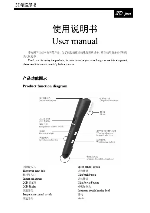
使用说明书Usermanual感谢阁下信任本公司的产品,为了使您能更愉快地使用该设备,请在使用前务必仔细阅读此说明书。
Thank you for using the products,in order to make you more happy to use this equipment,please read this manual carefully before you use.产品功能图示Product function diagram电源输入孔The power input hole耗材导入口Import and exportLCD 显示屏LCD display调温开关Temperature control switch调速开关Speed control switch 退丝按键Wire back button 送丝按钮Wire forward button 喷嘴加热头Integrated nozzle heating head 挂钩Hook规格定义及电气参数Specifications and parameters:出料方式:热熔挤压堆积成型Discharging mode:hot melt extrusion molding 成型方式:三维成型Molding:three-dimensional molding打印范围:无限定Print range:Unlimited吐丝速度:可调Spinning speed:adjustable 温度:60℃-245℃可调T emperature:60℃-245℃adjustable 设备工作电压:12V2AWorking voltage:12V2A equipment喷嘴直径:0.7mmThe nozzle diameter:0.7mm耗材直径:1.75mmFilament diameter:1.75mm特征Characteristic:·LCD屏能显示耗材种类、速度、温度、警告信息LCD display can directly show the information like filament type,speed level,temperature, warning,more humanized display interface.·支持ABS和PLASupport shift between PLA and ABS·2A供电,能耗低Max working current is2A,lower energy consumption·人体工学设计,注重用户感受Human engineering design,Pay attention to the user experience·点触式调速调温,智能切换材料所需温度Smart program control,simplifies use,intelligent filament replacement are used for the first time,this makes the user more convenient,more secure to change and replace the filament.警告!Warning!1.此设备适用于8岁以上儿童和成人使用。
An instruction manualDirectoryFirst,note..................................................................................................... 错误!未定义书签。
1 security matters ....................................................................................... 错误!未定义书签。
1.1 traffic safety first ................................................................................... 错误!未定义书签。
1.2in the hospital should be shut down .................................................. 错误!未定义书签。
1.3on the plane should be shut down..................................................... 错误!未定义书签。
1.4 gas should be shut down.................................................................... 错误!未定义书签。
1.5 in the blasting site near shutdown of................................................. 错误!未定义书签。
2the use of mobile phone......................................................................... 错误!未定义书签。
电子书手册组件部件名称 内部及外部 字符输入键屏幕配置 书籍 音乐 录制 备忘录 日志347第 1 章 入门组件为改进产品性能或质量,组件内容可能会变更,恕不另行通知。
各部件名称部件的外表及所印刷或刻印的内容可随型号或各部件的名称而异。
产品的外部/内部产品的外部/内部字符输入键屏幕配置书籍书籍类型书籍列表当前时间/日期所选的书籍收藏书籍电池阅读进度屏幕配置备忘录备忘录列表所选的备忘录第 2 章 了解基本功能连接 连接耳机 插入/卸下 SD 卡 推荐使用的 SD 卡 连接计算机 将文件(文件夹)复制至产品 删除文件/文件夹 断开与计算机的连接17开机/关机 开机关机使用锁住和重置功能 使用锁住功能使用重置功能选择菜单选择想要的菜单充电 通过连接到电脑充电13141516开机/关机开机1. 将【锁住/电源】开关滑至右端,即可开机。
关机1. 产品开启后,将【锁住/电源开关】滑至右端,即可关闭电源。
使用锁住和重置功能使用锁住功能1. 将【锁住/电源开关】滑至左端,即可锁定该产品。
2. 将【锁住/电源开关】滑至右端,即可对该产品解锁。
使用重置功能1. 若程序暂停且按键不起作用,打开产品底部的护盖,并用带尖端的工具 按【重置孔】。
2. 将【锁住/电源】开关滑至右端,即可开机。
使用重置功能时,当前时间及存储于内存的数据不会删除。
在产品运行过程中切勿使用重置功能。
这可能会对内存造成严重损害。
选择菜单选择想要的菜单由于 EPD 的特征,可能会出现以下情况,但产品仍可正常运行。
- 在菜单间移动时屏幕闪烁且响应缓慢。
- 屏幕可能出现残影。
- 若在极冷或极热的环境下使用,残影现象可能更严重,屏幕切换可能非常缓慢。
(工作温度: 0 ˚C~ 40 ˚C)- 若在明亮的阳光下使用,屏幕上可能出现横线。
(若转移到遮荫处使用,将正常工作。
)连接耳机1. 将耳机连接到耳机端口。
耳机必须另行购买。
插入/卸下 SD 卡1. 关闭电源,将 SD 卡(见下图)放入 SD 卡插槽,并轻轻按紧。
X300Pro3User ManualStatementThis handbook is the manual of X300Pro3.Without the written permission from the manufacturer, any company or individual shall not copy or backup it in any form(electronic,mechanical, photocopying,recording or otherwise).This manual is only operating instructions for X300Pro3.If any result caused by using it on other equipment,the company does not assume any responsibility for it.If not quality problems of X300Pro3such as equipment failure caused by user abuse or misuse, unauthorized disassembly,repair equipment yourself,not operate or maintain by the instructions, lose it,the repair will not be free.Other product names mentioned in this manual are in order to describe how to use X300Pro3,and their copyrights are still observed by the original company.X300Pro3and files are used for normal vehicles maintenance.If used for illegal purposes,the company does not assume legal responsibility.ContentChapter1:Summary (1)1.1Features (1)1.1.1Advantages (1)1.1.2Durability (1)1.2Introduction of the device (2)1.2.1The main unit and accessories (2)1.3Hardware technical specification (3)1.4Functions Setting (3)1.4.1Functions Selection (4)1.4.2System Setting (4)1.4.2.1Language Selection (4)1.4.2.2Contrast Adjustment (5)1.4.2.3Font Setting (5)1.4.2.4Metric/Inch………………………………………………………………………..1.4.2.5Data Logging……………………………………………………………………..1.4.3System Information (5)1.4.4Device Self-test (6)Chapter2:How to update software for X300PRO3 (6)2.1Update Tool software Installation (7)2.2Software Updating (8)Chapter1:Summary1.1.Features1.1.1.AdvantagesMulti-language environment can be applied in different countries and regions.The main unit system adopts ARM high speed chip to keep it running fast,stable and anti-jamming.Updating via SD card at any moment.Modern design and high-definition true color screen realize the integration of automotive industry and electronic information technologies and make auto diagnosis and key programming easier,practical and economical.1.1.2DurabilityIntegrity structure design makes it crack resistance,shock resistance and durable.Industrial design ensures the tool work stably under tough environment, such as high and low temperatures.1.2Introduction of the device1.2.1The main unit and accessories(Picture as below)Name InstructionTesting cable port Connect to the main test cable for autokey programmingDisplay Screen Show informationF1Keyboard input option keyF2Keyboard input option keyEnter OKESC Exit or give upUp UpRight To rightDown DownLeft To leftTF card slot To keep diagnostic program or data1.3Hardware technical specificationDimension:23.9cm(L)*12cm(W)*3.6cm(H)CPU:ARM7Power Supply:DC12VOperation Power:DC12VOperation Temperature:-20~60Display Screen:320*240TFT Screen1.4Functions SettingPower on and then press ENTER on the screen then go to the function setting, setting information as shown below:1.4.1Function SelectionSelect different functions according to different requirements.Note:Software numbers and functions are different according to different product configuration.Further detailed information,please contact your distributor.1.4.2System SettingSelect System Setting,language and contrast can be adjusted,as shown below:1.4.2.1Language SelectionThis device supports simplified Chinese,traditional Chinese,English,Russia,Greek, Spanish,Italian.In the language directory,select required language by Up and Down and press ENTER to confirm it.1.4.2.2ContrastAccording to the environment,adjust the brightness of the screen by the left andright buttons,as shown below:1.4.2.3Font SettingAccording to requirement,select different font.1.4.2.4Metric/InchAccording to different requirements,select the Metric/Inch by the up and down keys, and press ENTER to confirm as show below,1.4.2.5Data LoggingAny problems during testing,please use the Data Logging function to record the test process and send the data to us.Select ON by the up and down keys and press ENTER to confirm,shown as below,Note:Every time you need to select ON if you want to record the data before testing car.1.4.3System InformationSystem information includes product serial number,hardware version,software version,release date,register password,etc.1.4.4Device Self-testDevice self-test includes screen display,keyboard testing.hardware self-testing,etc. If it cannot show enough pictures on the screen,keyboard not work,and hardware self-test not get through,please return this X300Pro3to the manufacturer.Chapter2:How to update software for X300Pro32.1Update Tool software installationDownload the update tool and diagnostic software on ,double click,then go to the next step:Step1Click“Next”Step2:Click“NextStep3:Click“Next”Step4:Click“Finish”2.2Software UpdatingAfter Update Tool installationcompleted,click the Update Toolsoftware icon on desktop to start the update tools.Operation steps asfollowing:Step1Open update toolStep2Click the source menu,choose theprogram you want to update,click it and confirmStep3:Click and select all the software then click“update”Step4:Wait for several minutes then the updating finishedNote For new update software and questions during updating,please contact your distributor.。
User Manual Abbreviations - How to Write Abbreviations are widely used in technical documentation, including user manuals, to simplify and standardize the writing process. They serve as a convenient way of conveying complex terms or phrases in a concise manner. In this user manual, we will provide a comprehensive guide on how to write and use abbreviations effectively.Why Use Abbreviations?Abbreviations are used to enhance readability, reduce word count, and provide a standardized approach to technical writing. By replacing long and repetitive terms with abbreviations, users can quickly grasp the meaning behind the concept without being overwhelmed by lengthy explanations. Additionally, abbreviations facilitate the process of translating documents into different languages, ensuring consistency across various language versions of a user manual.Guidelines for Creating AbbreviationsWhen creating and using abbreviations in user manuals, it is crucial to follow some guidelines to ensure consistency and clarity throughout the document. Here are some key guidelines to consider:1. Create Abbreviations When NecessaryOnly create an abbreviation when it offers a significant advantage in terms of readability and reducing word count. Avoid unnecessary abbreviations, particularly for terms that are already widely known and understood by the target audience.2. Full Term IntroductionIntroduce the full term or phrase before using an abbreviation for the first time in the document. This helps the readers understand the meaning of the abbreviation and ensures clarity.3. Consistency in UsageMaintain consistency in the usage of abbreviations throughout the entire user manual. Always use the same abbreviation for a specific term throughout the document.4. Avoid Acronyms ConfusionDifferentiate between abbreviations and acronyms. An abbreviation is formed by taking the initial letters of a term or phrase, while an acronym is an abbreviationformed from the initial letters of multiple words that can be pronounced as a word. Make sure to clarify the difference between both in the user manual.5. Use Abbreviation ListInclude an abbreviation list at the beginning or end of the user manual. This list will provide users with a quick reference for all the abbreviations used throughout the document.6. Limit the Number of AbbreviationsTo avoid confusion, limit the usage of abbreviations to a necessary minimum. Overuse of abbreviations can lead to comprehension difficulties and make the document harder to read and understand.Writing the AbbreviationWhen introducing the abbreviation for the first time, follow these steps:1.Write the full term or phrase, followed by the abbreviation inparentheses. For example, User Interface (UI).2.Make sure the abbreviation is capitalized if the full term or phrasestarts with capital letters.3.Place a comma after the abbreviation, and continue the text withoutany special formatting.Once the abbreviation has been explained, it can be used consistently throughout the user manual without the need to reiterate the full term or phrase.Using Abbreviations ResponsiblyWhile abbreviations can significantly improve readability and reduce word count, it is essential to use them responsibly. Consider the following points:1.Do not overuse abbreviations, especially in sections that requiredetailed explanations or when addressing novice users.2.Avoid using abbreviations in headings, titles, or section subheadingsto ensure clarity.3.Aim for maximum comprehension by choosing the most suitableabbreviations based on user familiarity and industry standards.ConclusionUsing abbreviations in user manuals is an effective way to enhance clarity, readability, and consistency. Following the guidelines provided in this manual will ensure that your document remains understandable and properly conveys information to the intended audience. Remember to use abbreviations responsibly and sparingly, keeping in mind the needs and knowledge level of your users.。
User Manual - Abbreviation in EnglishIntroductionThe User Manual, also known as the instruction manual, provides vital information on how to use a particular product or service effectively. It serves as a reference guide for users, helping them navigate through various features and functionalities. In this document, we will discuss the importance of abbreviations used in English user manuals and their significance in enhancing communication.Why Use Abbreviations?Abbreviations play a crucial role in user manuals as they provide concise and efficient communication. By condensing lengthy terms or phrases into shorter forms, abbreviations help save space and make the content more readable. Moreover, they facilitate easy comprehension, especially in instances where repeating a certain term multiple times may lead to redundancy and confusion.Consistency in AbbreviationsMaintaining consistency throughout the user manual is essential when using abbreviations. A consistent approach ensures clarity and avoids confusion among users. Here are some guidelines to follow:1.Define abbreviations: Every abbreviation used in the manual shouldbe defined clearly when first introduced. This helps users understand theirmeaning and facilitates better comprehension throughout the document.e standardized abbreviations: If there are standard abbreviationsrecognized within specific industries or fields, it is advisable to adhere to those conventions. This aids in establishing a common language and avoids ambiguity.3.Consistent formatting: Ensure that the formatting of theabbreviations remains consistent throughout the document. This includescapitalization, punctuation, and any additional styling used for emphasis.Abbreviation PlacementAbbreviations should be strategically placed within the user manual to maximize their effectiveness. Here are a few ways to achieve this:1.Headers and titles: Abbreviations can be used in headers and titlesto provide a concise overview of the section’s content. This allows users toquickly scan and locate the information they need.2.Paragraphs and bullet points: Within the body of the manual,abbreviations can be incorporated to condense lengthy explanations orrepetitive terms. This helps keep the content concise and focused.3.Tables and diagrams: When using tables or diagrams to present dataor instructions, abbreviations can be utilized to save space and enhancereadability. However, it is crucial to ensure that their meanings are clearlydefined in the accompanying text.Benefits of Using AbbreviationsUsing abbreviations in user manuals offers several benefits:1.Enhanced readability: Abbreviations help users navigate throughthe manual quickly and easily, by reducing the length and complexity of thecontent. This makes the overall reading experience more efficient and user-friendly.2.Space-saving: By condensing lengthy terms, abbreviations savevaluable space, especially in cases where there are limitations on documentlength or size. This is particularly advantageous in the digital space whereconcise content is preferred.3.Improved user experience: Abbreviations contribute to astreamlined user experience, as they allow users to find information morequickly and efficiently. This can lead to increased satisfaction and a positiveperception of the product or service.ConclusionAbbreviations are a valuable tool in user manuals as they contribute to effective communication, enhanced readability, and a streamlined user experience. By adhering to consistent formatting, defining abbreviations, and strategically placing them throughout the document, the user manual becomes a more concise and user-friendly reference guide. It is important to remember to avoid using excessive abbreviations, as this may lead to confusion. When used appropriately, abbreviations can greatly enhance the overall quality and effectiveness of a user manual.。
WinJet高解像喷码机操作说明书型号 220 280 C2系列WinJet 为商标220 C2 280可喷印的最大高度18mm (单位:毫米)220 C2 可编辑信息行数为2行280 可编辑信息行数为8行V6.07-18 为本机的软件版本号WinJet公司保留更新产品性能及参数的权利,若有更改不另行通知。
目录喷印机220 280 C2喷印机是用于喷印文字(包括点阵以及实体中英文)、图形的高解像喷墨印字机,喷印字高2 mm -18mm。
速度220 280 C2喷印机喷印速度高达35米/分钟.墨盒220 280 C2喷印机使用高技术喷印头,建议您只使用由WinJet公司提供的专用环保油墨,否则喷印孔可能损坏,并丧失保修的权利。
注意:请不要混合使用不同型号的油墨,即使它们都由WinJet公司所提供,这将严重损坏机器并散失保修的权利环境与位置环境使用稳定的电压与电流,避免瞬间高压与干扰。
干扰不要安装喷印机在电磁场辐射区附近,例如:高频封口机、金属探测器等。
安装为了能获最好的喷印质量,请将喷印机安装于流水在线,并使被喷印的产品稳定通过流水线。
任何翘起的边角通过喷印机头,都有可能降低喷印质量。
在产品与产品之间请保持一定的间距,不要靠在一起或迭在一起,以便红外传感器(电眼)能正常工作。
220 280 C2喷码机喷印头可朝下或水平安装.控制喷头与产品的间距在5-8mm之间挡板带倒角,使纸箱边角不破损以致于损坏喷头固定架固定架必须坚固,不振动。
耗材 220 280 C2喷码机不需使用压缩空气。
220 280 C2喷码机必须水平安装,否则容易造成墨水滴落或墨水不能正常喷出。
电压设置220 280 C2喷印机使用电压(交流220伏/60H)油墨墨水供应采用墨盒,更换墨盒简单,干净,便利。
更换墨盒时,按下墨盒固定弹片,然后拉出旧的墨盒,插入新墨盒,使挤压孔朝下。
当墨盒穿入时,会有一点阻力,但不要太用力。
如果墨盒安装不太容易,请检查挤压孔是否朝下,并且墨盒凸起的部分是否朝前。
如果更换墨盒的时间只有几秒钟,那么喷印机可以继续喷印,并且空气不会被吸入油墨孔;如果被吸入油墨孔,那么就需要将其消除,即挤压出空气。
如果觉得没把握,请关机后更换油墨盒。
机器在任何时候都必须安装墨盒,否则会污染喷印机油墨系统。
在任何时候都不能把手指伸入墨盒槽,因为槽内尖锐的针会损伤手指。
远红外传感器远红外传感器必须安装于喷印头的前方,不管是左边或右边,要根 据产品的运动方向而定。
当远红外传感器感应到该产品的起始边时, 喷印机开始计时,在延迟时间到达时开始喷印。
产品与产品之间要有间隙,否则传感器将不工作,喷印机也不喷印。
选配喷印头当要向下喷印或在有限制的空间喷印时。
在安装喷印头时,一定要注意喷头与墨盒之间的相对位置: ☑如果喷头的安装位置高于建议的位置,那么喷印机将不能喷印。
☑如果喷头的安装位置低于建议的位置,那么油墨将从喷头漏出。
安装喷印头时,喷印头孔底部与机器底部的距离为30mm~ 50mm ,高于 50mm 喷印头将不喷印; 低于30mm ,墨水将 从喷印头流出。
喷头保护 传感器装在 右边 产品运动方向红外传感器装在左边产品运动方向30-50 mm 30-50 mm 喷头孔底部喷头孔底部 机器底部 机器底部安装(继续)最后检查喷印之前安装完毕,喷印之前:☑装入墨盒。
☑打开电源开关。
☑清洗喷头,按墨盒挤压按扭(参阅挤压墨盒)。
☑输入喷印信息(参阅喷印信息编辑与选择)。
☑在主菜单下,按键或键,启动喷印功能。
装运当要装运机器时,请务必按以下步骤包装设备:☑当不取出墨盒时,包装及运输过程中要始终保持喷头位于墨盒的上方。
如果不这样做,在运输过程中墨水将从喷头流出。
☑请安装喷头保护片于喷头之前,保护片不能接触喷头,这样可以保护喷头不被包装物污染或损坏。
☑确认您的包装在运输过程中不会因为其它意外的情况损坏喷头,因为喷头是喷码机的主要部分。
结束语关机连续喷印过程中,喷头上的油墨不会干。
正常关机只是把电源开关关闭。
长时间关机,建议装上喷头保护片,并使用包装材料包好喷头,但不能接触喷印孔(黄色条状)。
关机期间不必取出墨盒,否则污染物会进入油墨系统。
关机时间超过三天以上,维护请参阅日常维护节。
不论在任何情况下,都不能用任何材料(无论多柔软)擦喷印,只能使用 WinJet公司提供专用清洗剂,否则损坏喷印头。
当机器不用时,请将墨盒留在机器里,并水平放置机器。
键盘220 280 C2键盘根据相关功能分组排列,:喷印信息编辑与选择喷印信息220 280 C2喷码机可以储存100条信息。
每行700列个字符,但是一次只能喷印一条信息,这条信息称为喷印信息. 开机显示主菜单:新建和编辑 用于新建一条新的喷印信息或编辑已存在的喷印信息。
移动光标至:目标文件号:00 ,然后直接输入您所要喷印或编辑的 文件号,按 进入信息编辑菜单。
编辑菜单如下图所示按 键进入编辑接口编辑接口如下图所示,00 文件为测试喷印信息。
字高 18mm 英文 计数 C 实体0001喷印信息编辑与选择(继续)1. 将光标移动到您想要的位置2. 按 选择字高,按 选择中文、英文或图形,按选择 计数器及有效期。
3. 按 删除光标所在的字符,同时按 + 清除全屏 4. 按 退出即保存5. 按 或 进入喷印状态中文输入1. 在信息编辑状态,按 选择Lang 状态(中文输入状态)2. 按 查看中文编码,按 查看下一页。
3. 查到您所要的汉字后,记下所对应的坐标,比如:年的编码为0014. 按任意按键退出5. 在光标所在位置输入该汉字的编码6. 目前中文字库为各种字高各100个0 1 2 3 4 5 6 7 8 9 字高 00 年月日期合格班次 18mm 01 中文 02 03 计数 04 C 05 点阵: 06 0001 0001正在喷印信息:03宽度:0033 加粗:3延迟:150 方向:1连续:0 颠倒:1 间隔:33333 同步:1 计数器A 计数器B 09:44:26 计数器C喷印信息编辑与选择(继续)图形输入1.在信息编辑状态,按 选择 Logo 状态(图形输入方式) 2.直接输入图形号码,00-99,目前共可存100个 3.220 280 C2只能接受最大512*64/512*128像素的图形,可变数据除了可以喷印固定的信息外, 还能喷印自动变化的数据, 比如:时间、日期等. 这些可变的资料如下: ☑ 日期 ☑ 时间 ☑ 计数日期编码当前日期的编辑1. 本机内部有日期记忆功能,即使在断电状态也能自动跟踪当前日期2. 如需要输入当前年,月,日,按 来选择Y0、M0、D0,并按 键确定。
3. 如需要输入四位的年, Y0前面键入20有效日期的编辑在编辑菜单状态,按 进入有效日期设置菜单1. 未来日期 1为从现在日期起加几月,分别用Y1,M1,D1 表示 2. 未来日期 2为从现在日期起加几日,分别用Y2,M2,D2 表示 3. 移动光标并修改未来日期 1或未来日期 2 4. 按 退出并保存5. 在信息编辑状态输入:Y1,M1,D1 或 Y2,M2,D2有效日期设置有效日期1(月)=当前日期0 + 06月 有效日期1(日)=当前日期0 +365日喷印信息编辑与选择(继续)编辑时间1. 220 280 C2喷码机 内置时钟,无论您通电或断电,时钟都会继续工作。
2.在编辑信息状态,将光标移动到希望插入时间的位置,按 切换至HH,MM,按 键确认.计数器1.在信息编辑菜单状态,按 进入变量编辑菜单。
2.将光标移动到 Digits:4设置计数器的位数为4(代表该计数器的开始值从0000到99993.将光标移动到A/B:1 C:1 数值为1 代表加计数器,为0代表减计数器计数器 设置 计数器 A 计数器 B 位数:4 位数:4 初值:9999 初值:9999 步值:15 步值:15 终值:0001 终值:0001 计数器 C 增/减位数:8 A/B:1 C: 1喷印信息编辑与选择(继续)计数器当前值设置在主菜单状态,按 进入计数器当前值设置菜单。
1. 将光标移动到Counter A:或者Counter B:或者Counter C: 2. 输入希望修改的数值 3. 按 保存修改并退出有关如何添加或修改字体(请参照随机光盘中的Software Demo 文件)有关如何将自定义的字体传输到喷码机中(请参照随机光盘中的Software Demo 文件)计数初值设置 计数器 A:0263 计数器 B:0001 计数器 C:00000001喷印喷印位置 喷印之前大部分纸箱都需喷印信息于特殊的位置,比如,在方框中或纸箱空白的位置,所以在喷印之前须安装喷印机在适当的位置。
另外,还需要设置输送线和纸箱的运动方向等喷印参数在喷印状态或主菜单状态,按 进入喷印参数编辑菜单1. 宽度为喷印信息的宽度,数字大为宽,数字小为窄 2. 延迟为喷印信息的位置3. 同步器选0为不使用同步器, 选1为使用同步器;方向选0或1为相反方向;连续0为不使用连续喷印,选1为使用连续喷印;倒置0或1倒置喷印开始喷印大部分纸箱都需喷印信息于特殊的位置,比如,在方框中或纸箱空白的位置,所以在喷印之前须安装喷印机在适当的位置。
另外,还需要设置输送线和纸箱的运动方向等喷印参数喷印参数设置 宽度:0033 加粗:1 延迟:150 方向:1 连续:0 倒置:1 间隔:33333 同步:0Yes=1No=0Effect of changing the Delay on message position (exaggerated)Delay = 00Delay = 20Delay = 40MESSAGEMESSAGEMESSAGE喷印(继续)信息喷印位置为了使喷印的信息易读、明了,信息必须喷印于产品的正确位置。
垂直方向的定位: 上下移动喷印机的相对位置。
水平方向的定位:可以使用延迟喷印功能。
在您改变喷印信息之前,请确认输送线的正常运行速度。
如果输送线的运行速度是可变的。
那么喷印的位置和整个信息的宽度都是变化的,对于这种情况,可以加装同步器来确保喷印的位置的 准确性。
在喷印状态,若您要改变喷印的延迟设置,请按 或 键, 延迟设置在改变后立即生效。
喷印机的红外光电眼在读到喷印物体的边缘时,开始计时,至延迟时间值时,喷印机开始喷印。
注意:根据喷印物体运动方向的不同, 信息可能从左边第一字符开始喷印或从右边第一字符开始喷印。
喷印 (继续)设置喷印信息的宽度220 280 C2喷码机可以人工设置控制喷印字符宽度,也可以使用同步器自动控制喷印宽度若您要调整喷印宽度,在喷印状态,若您要改变喷印的延迟设置,请按或设置在改变后立即生效。
注意:如果您同步器选择“1”是,而您没有安装同步器,那么喷印机将不喷印。