user-manual用户使用手册
- 格式:pdf
- 大小:2.22 MB
- 文档页数:50
产品基本介绍一、概况1、采用标准的2U高度机箱,由1.5毫米钢板经数控加工而成,加之优质的喷涂,提供了一个精确、坚固、美观的构造。
2、本功放采用原装进口元件,并经过严格的测试。
安装时经过特别的加固,以适应震动等恶劣环境。
3、信号采用卡侬座平衡输入输出。
功放输出采用红黑接线柱和speakon插 座。
为固定安装和流动演出提供最可靠最灵活的连接。
4、电源采用优质的环形变压器,大容量音频专用滤波电容,为本机提供的低纹波,高储备的能量来源。
5、本机具有软启动线路,减小开启瞬间的冲击电流,从而有效保护机内元件,并减少对电网的冲击和对其它设备的干扰。
6、大型散热器,左右对称布局,配合优质滚珠轴承风扇形成2个独立风道,能够最有效的降低功放管的温升。
7、内置压限电路,自动监测输出信号,控制输入信号大小,因此本机不会长时间处于削波状态。
并能将功放的输出功率固定在一安全的区域内。
而不受前级输入信号的影响,使用更加放心可靠。
8、完善的保护线路,包括直流中点飘移保护、过热保护、输出过载保护、 软启动保护、大信号保护、欠压保护。
9、输入灵敏度可选择,适应多种音源。
应用参考二、安装与使用1)请将本机放置于平坦,稳固和通风良好的地方。
2)选取外形适配,足够容量的固定插座,连接本机的电源插头,注意一定要牢固可靠,并关闭开关。
3)将音量电位器逆时针旋转到最左边,将信号线通过卡侬公插头平衡式连接到本机的信号输入座。
4)将音箱通过专用的音响线连接至本机的接线柱或者是Speakon输出座。
5)先开启前级信号源的电源后再开启本机电源,顺时针旋转音量电位器,调 整为你所需要的声音大小。
三、注意事项1)请确保机箱上的通风孔没有任何阻塞。
2)请勿在本机上放置重物。
3)移动本机时请小心勿掉落地上或者强烈撞击,并先要确认电源已关闭, 后面板所有连接线已经拔掉。
4)长时间大功率使用后本机将产生一定热量,变速风扇加速散热产生噪声。
但是不属于故障,当温度降低后上述现象将消失。

电池及充电说明Slypod使用内置锂电池,首次充电使用时,请先给Slypod充满电以激活电池,保证产品顺利使用。
红灯常亮表示设备充电中,蓝灯常亮显示充电完成。
Slypod使用Type-C接口,手机充电器、移动电源等都可以给Slypod充电,电池充满后将停止充电。
1.使用Slypod过程中,请使用包装内提供的原装充电线!2.切勿过充、过放电池,否则将对电芯造成损害;3.若长期闲置电池,请每隔3个月左右重新充放电一次以保持电池活性。
IOS Androidb. 打开MOZA Master选择要连接的产品,点击连接,完成连接,c. 连接成功后选择产品,进入该设备的操作界面。
注意:首次连接需根据引导流程进行产品激活。
请以最新版本APP为准;如有更新,恕不另行通知,请关注官网、微信公众号各大应用商城。
通过App控制Slypod时,除点击拍照,控制相机拍摄一张照片设置设备上下移动速度操作原点显示当前设备移动距离66mm设备伸出最大长度280mm长按设备下移松开停止运动● 普通模式长按设备上移松开停止运动点击拍照,控制相机拍摄一张照片显示当前设备移动距离66mm设备伸出最大长度280mm单击设备下移再次单击停止运动● 变速模式单击设备上移再次单击停止运动滑动红色操作点从起点至任意位置,设备会跟随滑动。
长按向上移动,设备会向上移动,松开停止运动;长按向下移动,设备会向下移动,松开停止运动。
双击向上移动,设备自动向上运行;再次单击,设备停止运动。
双击向下移动,设备自动向下运行;再次单击,设备停止运动。
点击拍照,Slypod 控制相机拍摄一张照片(Slypod 需连接相机控制线,相机控制线需另购)。
速度设置:点击设置设备运行速度,设备按照所设置的速度持续运动。
单击向上移动,设备自动向上运行,再次单击,停止运动; 单击向下移动,设备自动向下运行,再次单击,停止运动;点击拍照,Slypod 控制相机拍摄一张照片。
( Slypod 需连接相机控制线 )速度设置:点击设置设备运行速度,设备从当前速度运动到设置速度再减速运动到终点位置(终点位置速度为0)。


微软用户[选取日期]前言非常感谢您选择了力高新能EK-FT-11电动汽车电池管理系统(BMS: Battery Management System),为了使您能够更好地安装、使用和维护本产品,请在安装和使用前仔细阅读本用户手册(以下简称手册)。
EK-FT-11是力高新能针对电动汽车发展需求开发的新一代电池管理系统。
根据大型电动车的强干扰、高电压、高稳定的需求特点,EK-FT-11的设计具有极强的适用性。
根据组件的不同选择及配置,可满足客户各种不同应用需求,提供优异的产品性能。
EK-FT-11通过有效的隔离及设计方式可较好的屏蔽电动车上较强的电磁干扰,通过汽车级处理器芯片、CAN总线通信方式及高冗余度性的硬件及软件设计,显著提高了系统的安全性、稳定性、可靠性。
1.1 提示本手册包含客户必须掌握的重要信息,如客户未严格按照本手册安装、使用和维护本产品,本公司将不承担相关后果或责任。
1.2 企业资质及相关认证1.3 声明为求准确,本手册已经过复审和验证。
本手册包含的指导和描述对EK-FT-11电池管理系统是准确的,但是由于技术的改进,后续的EK-FT-11电池管理系统及手册可能变动。
EK-FT-11产品突出优势⏹高准确率——采用独有Vmin-EKF 算法(业界最精确的SOC 的估计算法),电池剩余容量估计SOC 精度已达到95%以上,业界领先;⏹高精确度——基于独有的D-Filter 算法高精度采集系统,系统参数(如单体电压)采集误差均在0.2%以内;温度采样误差±1℃(-20℃~85℃),电流采样误差±1A ;⏹高安全性——双重隔离电路及主动保护技术、强电安全、电磁兼容设计、多重主动保护技术(全面的安全管理和控制系统);⏹高效均衡——领先的高频开关电路与温度保护技术(电池智能均衡技术)的使用,可同时控制多路电池均衡,总均衡电流可达到1A ,并通过温度监控、均衡失效等多重保护,确保均衡电路的稳定可靠;⏹强可靠性——创新优化结构设计;系统电路采用高冗余度设计,同时支持CAN 总线和高压继电器两种充放电控制方式;通过EMC 测试、高低温老化、防水防尘以及振动实验等,保证系统可靠运行;采用多重电源隔离方案,使得系统采样和通信的可靠性大大提高;BMUBMUBMUBMUBCU仪表Batterymodule 1Battery module 2Battery module 3Battery module nB U S电机控制器整车控制器⏹CAN 总线通讯功能——可通过多重隔离的CAN 总线实现与整车控制器/电机控制器、仪表及充电机之间的智能交互,实现各种信息的有效共享;EK-FT-11电池管理系统用户手册⏹绝缘监控功能——绝缘检测模块能够有效地检测电动汽车绝缘状况,实时显示绝缘故障等级,确保人身安全;⏹实时显示——通过RS485/CAN接口与上位机或显示屏进行通讯,实时显示电池组电压、温度、SOC、故障等信息;⏹强电控制——将强电控制系统和电池串管理单元独立设计,实现强弱电的有效隔离,避免串扰,提高电磁抗干扰能力,保证系统安全可靠运行;⏹系统上电自检——系统上电后对电压、温度、通讯、显示等功能进行自动检测,保证系统自身的工作正常。
USER MANUAL 嵌入式电源模块用户手册COMPACT SYSTEMAD-2U220S2430嵌入式通信电源模块——用户手册1前言欢迎您使用由本公司研发生产的嵌入式电源模块,模块为一体化设计,整机性能稳定,实用性强。
声明1. 规格书详细描述了嵌入式电源模块的各项性能,在对电源模块进行各项操作前,请用户仔细阅读本规格书,遵守相关行业的安全规范。
对于操作不当或者超出本规格书规定之使用条件导致产品损坏,本公司概不负责。
2. 我公司有权利在不通知客户的情况下更改手册的内容。
安全守则高压 交流引入线为高压工作线路,操作过程一定要确保交流输入断电,操作过程中对不许动用的开关要加上临时禁止标识牌。
注意 交流线路端子接点及其它不必要的裸露之处,要充分绝缘。
注意 上电之前必须接地。
严禁在雷雨天气下进行高压、交流电操作——用户手册2——用户手册4COMPACT SYSTEMAD-2U220S2430嵌入式通信电源模块——用户手册5七、其他特性项目 指标要求性能 机器噪音 输入电压和输出电压电流范围内,距离电源前、后、左、右1米,距离上、下1.5米,电源的噪音应小于55dB(A) 通过 MTBF 100,000H通过 振动 5~9Hz ,振幅3.5mm ,9~200 Hz ,加速度10m/s2,3轴向,每个方向扫频振动5次(3*50分钟),电源不损坏。
通过 冲击 半正弦波,加速度为20G ,脉冲宽度为11ms ,X 、Y 、Z 三方向,各三次 通过 防尘 有一定的防尘功能 通过 气味无异味或有害性气体通过第三章 外形图及接口定义、告警指示一、整机外形图整机尺寸:深(290mm )*宽(482.6mm )*高(89mm )二、安装尺寸图COMPACT SYSTEMAD-2U220S2430嵌入式通信电源模块——用户手册6DISPLAY输出显示电源开关Power高频开关电源High frequency switching power supply并机信号及接点直 流 输 出 DC OUTPUT1路2路交流输入 C OUTPUT电 池 输 入 +电 池 输 入 - 直 流 输 出 +直 流 输 出 -后视图三、端子接口定义浮充:可旋转调节 均充:可旋转调节 Fail:故障时亮 Run:运行正常亮LED 显示 切换开关 拔码开关:均浮充转换 总开关COMPACT SYSTEMAD-2U220S2430嵌入式通信电源模块——用户手册7交流输入(L 、N 、E ) 干结点输出 负载输出保险空开 电池(+)电池(-)负载(+)负载(-)温馨提示 接线方式:可将电源输出正极(红色接线柱)接通信设备如交换机、光端机等GND 地线,电源输出负极(黑色接线柱)接通信设备负极。

INSTALLATION AND OPERATIONUSER MANUALUM980BDS/GPS/GLONASS/Galileo/QZSS全系统全频高精度RTK定位模块修订记录权利声明本手册提供和芯星通科技(北京)有限公司(以下简称为“和芯星通”)相应型号产品信息。
和芯星通保留本手册文档,及其所载之所有数据、设计、布局图等信息的一切权利、权益,包括但不限于已有著作权、专利权、商标权等知识产权,可以整体、部分或以不同排列组合形式进行专利权、商标权、著作权授予或登记申请的权利,以及将来可能被授予或获批登记的知识产权。
和芯星通拥有“和芯星通”、“UNICORECOMM”以及本手册下相应产品所属系列名称的注册商标专用权。
本手册之整体或其中任一部分,并未以明示、暗示、禁止反言或其他任何形式对和芯星通拥有的上述权利、权益进行整体或部分的转让、许可授予。
免责声明本手册所载信息,系根据手册更新之时所知相应型号产品情形的“原样”提供,对上述信息适于特定目的、用途之准确性、可靠性、正确性等,和芯星通不作任何保证或承诺。
和芯星通可能对产品规格、描述、参数、使用等相关事项进行修改,或一经发现手册误载信息后进行勘误,上述情形可能造成订购产品实际信息与本手册所载信息有差异。
如您发现订购产品的信息与本手册所载信息之间存有不符,请您与本公司或当地经销商联系,以获取最新的产品手册或其勘误表。
UM980 User Manual前言本手册为用户提供有关和芯星通UM980模块的硬件组成信息。
适用读者本手册适用于对GNSS模块有一定了解的技术人员使用。
目录1产品简介 (1)1.1产品主要特点 (2)1.2技术指标 (2)1.3模块概览 (4)2硬件组成 (5)2.1机械尺寸 (5)2.2引脚功能描述(图) (7)2.3电气特性 (10)2.3.1最大耐受值 (10)2.3.2工作条件 (10)2.3.3IO阈值特性 (11)2.3.4天线特性 (11)3硬件设计 (11)3.1推荐的最小系统设计 (11)3.2天线馈电设计 (12)3.3接地与散热 (13)3.4模块上电与下电 (13)4生产要求 (14)5包装 (15)5.1标签说明 (15)5.2包装说明 (15)UM980 User Manual1产品简介UM980是和芯星通自主研发的新一代BDS/GPS/GLONASS/Galileo/QZSS全系统全频高精度RTK定位模块,基于和芯星通自主研发的新一代射频基带及高精度算法一体化GNSS SoC芯片—NebulasⅣTM设计。

User Manual 用户手册Mini MX 2 OverviewSmart Trigger1. The customized “MOZA Genie” APP for Mini MX 2 can help you make better use of the various functions of the gimbal.2. Please routinely check for the latest version of the MOZA Genie app. Make sure you have set to automatic update on your mobile smartphone. Installation and UnlockingPhone Holder OperationPower on and install the phoneLong press the power button to turn on the stabilizer. The phone holder will open automatically. Place the phone in the center of the phone holder, the phone holder will clamp automatically when a mobile phone is sensed.Follow the steps shown in the pictures below and unlock theCharging1. The MOZA Mini MX 2 has a built-in lithium battery. Before first use, fully charge it to condition the battery to ensure smooth operation.2. When the power indicator starts flashing, the battery level is less than 20%. Please charge it in time.3. With a universal Type-C port, Mini MX 2 can be charged by both phone charger and power bank.4. The battery will automatically stop charging when it gets fully charged. The blue indicator light will turn off. Please disconnect the charger.Power off and remove the phoneFirst press the trigger button and hold, while long press the power button, the phone holder will open automatically.Then remove the phone, the phone holder will close and gimbal will turn off when it no longer sense the phone.Phone holder operationPress and hold the trigger button and "+" button: The phone holder will openPress and hold the trigger button and "-" button: The phone holder will closeBattery Level Indicators● The blue indicator light is always on in three bars, and the power is 70%~100%;● Two bars of the blue indicator light arealways on, the battery level is 40%~70%,● The blue indicator light is always on,and the power is 20%~40%● The blue indicator light flashes once,and the battery level is 0%~20%● The blue indicator light flashes from top tobottom, and the gimbal is in upgrade mode● The blue indicator lights are on from bottomto top, chargingNote: The indicator light is off after fully charged when power off, and the indicator light is always on after fully charged when power on.Connecting to the MOZA Genie Appgimbal.Long press the function button for 3s to power on the gimbal, turn on the Bluetooth of the phone, launch the MOZA Genie App. Click the Bluetooth icon in the main interface of MOZA Genie App to search for connectable devices, select the device with the connection prefix as Mini MX 2. After successful connection, the gimbal will automatically enter the shooting interface.Mini MX 2 ActivationEnter the APP main interface to select the gimbal to be connected, the activation prompt box will pops up, click Activate. After the activation is completed, the gimbal will work normally. If activation fails, please try to reactivate, if it fails again, please follow the prompts to contact customer service.Button function (MOZA Genie App Control)Fn buttonLong press: on/offPower on and enter standby mode(phone not clipped/unlocked)Single press: shutter; record / stopWake up (gimbal in standby mode)Double press: switch to video mode/photo modeZoom + Click and hold: Zoom inSingle press: Pan-tilt followDouble click: Automatically zoom in to maximumZoom -Press and hold: Zoom outSingle press :FPV ModeDouble click: Automatically zoom out to minimumInception Mode:Push the joystick left and rightin FPV mode to control the rotation directionJoystickMove upwards: phone camera goes upMove downwards: phone camera goes downMove leftwards: phone camera goes leftMove rightwards: phone camera goes rightInception mode: Move leftwards, roll axis rotatescounterclockwise.Move rightwards, roll axis rotates clockwiseSmart TriggerClick and hold: All Lock ModeDouble click and hold: Sport Gear ModeOne-Click: Face Tracking and lock in thecenter of the shot.Double click: Re-center and exit the current modeTriple Click: Switch between the rear and front-facing cameraFirmware upgradeTurn off the power of the gimbal first, press and hold the ZOOM-button, and click the function button at the same time until the indicator light flashes from top to bottom, at this time the gimbal enters the firmware upgrade mode, then connect to the APP, and click firmware upgrade.Bluetooth resetWhen you cannot search for Mini MX 2 Bluetooth on your phone, please power on the gimbal, hold + button, then press the power button at the same time until the power indicatorflashes. Then the Bluetooth reset is successful.1. Make sure you've installed your phone, and check whether the mobile phone is well balanced. Serious unbalance will cause motor overload and goes to sleep to protect it.2. Please have a check whether the indicator flashes quickly, if it does, it means low battery and the gimbal can not work.3. What can I do if there is a delay in the movement and video in my App?1. Why does my gimbal automatically enters sleep mode after a short while of usage?2. Does the gimbal support fast charging ?Fast charging is not supported, the charging specification is 5V/2A1. Check whether the anti-shake function is turned on in the App, if it is, please turn off the anti-shake function.2. If the delay still exists after you turned off the anti-shake function, please uninstall the App and download it again. If the problem still exists, please contact our after-sale service.FAQ Product SpecificationRoll :300°Payload280g WeightGimbal Dimensions (L*W*H mm)Folded:145*60*180Supported PhoneWidth:60 ~ 88mm Battery Life2.5-Hours Battery capacity: 2000mAh Pan :340°Tilt :140°24 h(Reference battery life under test with gimbal well balanced.)Working votage: 7.4V Charging TimeMechanical Range 423g UnFolded:120*120*265Battery SpecsWeight:143~280g4. What should I do if × appears after I opened the App and searched Bluetooth?5. What should I do if the Object Tracking fails?6. What is Magic Mode?7. What should I do if the indicator light is not on and I can't turn the gimbal on due to upgrade failure?8. How to operate the Inception Mode?1. Press Zoom- to switch to FPV Mode2. Move the joystick left and right to proceed the operation for Inception Mode.Close Bluetooth search box in the MOZA genie app, then re-open the search box and search again the Bluetooth device, try to connect again.1. Please try to select a target of a suitable size in a single background environment. the screen and be clearly visible without any foreground objects.2. If it still doesn't work, please try to upgrade the App and gimbal firmware.1. The Magic Mode in MOZA Genie App provides some cool short clips filmming templates, you can easily shoot several clips by following the templates.2. The Magic Mode guide you record and filming from three aspects including "camera movement", "transition", "sound effect" to achieve "one step filming".3. You just need to hold a button to start shooting, the gimbal will automatically move according to the scene's requirements, and some may provide tips to users on following the camera movement.When upgrade failure happens, please force your gimbal enter firmware upgrade mode (also called boot mode, hold zoom- button then press fn button) and upgrade firmware again.认识Mini MX 2折叠状态下如图示解锁稳定器。
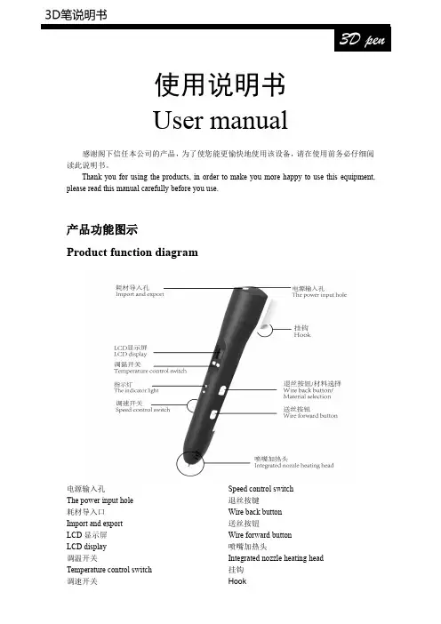
使用说明书Usermanual感谢阁下信任本公司的产品,为了使您能更愉快地使用该设备,请在使用前务必仔细阅读此说明书。
Thank you for using the products,in order to make you more happy to use this equipment,please read this manual carefully before you use.产品功能图示Product function diagram电源输入孔The power input hole耗材导入口Import and exportLCD 显示屏LCD display调温开关Temperature control switch调速开关Speed control switch 退丝按键Wire back button 送丝按钮Wire forward button 喷嘴加热头Integrated nozzle heating head 挂钩Hook规格定义及电气参数Specifications and parameters:出料方式:热熔挤压堆积成型Discharging mode:hot melt extrusion molding 成型方式:三维成型Molding:three-dimensional molding打印范围:无限定Print range:Unlimited吐丝速度:可调Spinning speed:adjustable 温度:60℃-245℃可调T emperature:60℃-245℃adjustable 设备工作电压:12V2AWorking voltage:12V2A equipment喷嘴直径:0.7mmThe nozzle diameter:0.7mm耗材直径:1.75mmFilament diameter:1.75mm特征Characteristic:·LCD屏能显示耗材种类、速度、温度、警告信息LCD display can directly show the information like filament type,speed level,temperature, warning,more humanized display interface.·支持ABS和PLASupport shift between PLA and ABS·2A供电,能耗低Max working current is2A,lower energy consumption·人体工学设计,注重用户感受Human engineering design,Pay attention to the user experience·点触式调速调温,智能切换材料所需温度Smart program control,simplifies use,intelligent filament replacement are used for the first time,this makes the user more convenient,more secure to change and replace the filament.警告!Warning!1.此设备适用于8岁以上儿童和成人使用。

An instruction manualDirectoryFirst,note..................................................................................................... 错误!未定义书签。
1 security matters ....................................................................................... 错误!未定义书签。
1.1 traffic safety first ................................................................................... 错误!未定义书签。
1.2in the hospital should be shut down .................................................. 错误!未定义书签。
1.3on the plane should be shut down..................................................... 错误!未定义书签。
1.4 gas should be shut down.................................................................... 错误!未定义书签。
1.5 in the blasting site near shutdown of................................................. 错误!未定义书签。
2the use of mobile phone......................................................................... 错误!未定义书签。

USER MANUAL 用户手册Digital basin faucet智控面盆龙头AXENT.ONE感谢您的信任衷心感谢您购买AXENT产品。
在使用产品之前,您可以从本手册中了解有关产品安装及使用方法等重要事项。
请您遵循本手册的记载事项。
请在阅读后妥善保管,以备日后需要时查阅。
因本公司产品不断改进,如有变更,恕不另行通知。
本手册插图仅为示意图,具体请以产品实物为准。
我们期待您能通过本手册掌握产品的安装及使用方法。
为确保该产品能提供最佳的功能及保证您的人身安全,我们请您:在首次使用前,认真阅读本手册。
安装和使用前,请仔细阅读以下安全须知,以便正确安装及使用产品。
注意以下警告,其与安全相关!凡不遵照下述条例所造成的损失,本公司将不承担任何责任。
■■安装资格要求:仅限经过专业训练合格的水电工进行产品的安装。
■■请以本手册为基准进行安装;擅自变更施工方法可能引起的不良后果。
■■说明书包含质保及产品清洁和保养等重要信息,请用户妥善保管。
■■公司保留维修时使用最新配件的权利。
标识说明符号说明危险!高风险,可能导致死亡或重伤警告!中风险, 可能导致重伤注意!低风险,可能导致轻伤温馨提示保护接地符号说明热水冷水要求检视检查密闭性请按国家相关规定进行废弃物分类处理降低触电或火灾的风险■■电路施工应遵守室内布线规程。
■■在墙上钻孔时,请确保在您准备钻孔的位置没有隐蔽的管道。
■■插座应自带能够保证安全的防水功能或防水附件。
■■如果电源线受损,请立即断电并联系当地供应商或致电服务热线更换电源线。
仅限具有相关资质或本公司授权的技术人员可以更换电源线。
■■作为电气设备,该设备不得在潮湿或湿润的环境中使用。
若该设备应用在浴室内,则应当安装排气扇或通风口,以确保浴室中良好的空气流通。
■■严禁将本产品带电部件放置或浸入水或其他液体中。
如不慎发生,请勿触碰产品带电部件并立即断电。
降低烧伤、触电、火灾或人员受伤的风险■严禁使用过松插座。
用户使用手册韩国现代HY-008一、前言感谢您选购本公司外置盒系列产品! 我们将带给您一个全新的、安全便捷的移动存贮器的新概念。
对于PC系统或MAC系统的用户,在扩充硬盘容量及提高数据的可移动性,提供了一个最佳的解决方案!在您使用之前,请您详细阅读本手册,以便更好的熟悉本产品。
二、系统要求:安装此驱动的环境条件:2.1.硬件需求:有一个空闲的USB接口的个人PC机、笔记本电脑或MAC机。
若系SATA、eSATA或1394机种,还要有相应的SATA、eSA TA或1394接口.2.2.操作系统:WIN 98/98SE、WINME、WIN2000、WINXP、VISTA,MAC OS 8.60 或以上版本。
三、性能:(1) 即插即用,支持热插拔;(2) 支持USB2.0,兼容USB1.1;(3) 支持SA TA接口(若是SATA接口机种);(4) 支持eSA TA接口(若是eSATA接口机种);(5) 硬盘所需运行环境: WIN98/SE/ME /2000/XP、VISTA,MAC OS 8.6 或以上版本。
四、包装配件:1.外置盒一台.2.驱动光盘一个3.USB数据线各一条)4.螺丝包一个5.干燥剂一包(勿食用)6. 螺丝刀一把(选配)五、SATA 接口硬盘的硬件安装:1. 从包装盒中取出产品,并打开产品面盖;2. 将内部的7PIN SA TA红色细扁数据线15P SA TA电源线, 插入SA TA硬盘上的相应7+15PIN接口。
3. 检查内部连接OK后, 装好盒子并锁紧镙丝;4. 插入USB数据电缆;最后打开电源开关.5. (1)这时电脑会识别到一个可移动硬盘.(2)点击移动硬盘图标可在您电脑的任务栏上会出现一个安全可移动硬盘的图标,点击它,在电脑依旧开机的情况下,您就可以安全移除硬盘盒。
(注: SA TA 或ESA TA有可能不会出现安全移除符号,要安全移除请在移动硬盘空闲以后,即读写灯不闪时)(3) 注意事项:本产品采用USB2.0接口,建议您使用高速USB2.0,以发挥产品的最高性能。
User Manual用户手册(指令,操作,维护)Reineke燃气热值仪(型号:RBM2000)用于连续高速测量热值、华白指数、密度和最少空气需求量Reineke Mess- und Regeltechnik GmbH德国莱纳克测量控制技术有限公司上海代表处目录1.0 介绍 3燃气特性 31.12.0 测量方法及运行原理 52.1 测量方法 52.2 运行原理 52.3 控制单元83.0 技术数据104.0 安装114.1 安装地点114.2 装配114.3 燃气连接144.4 连接电源和测量信号155.0 调试185.1 准备工作185.2 预设置19改变时间/日期19 5.21设置标定气19 5.225.3 数据采集316.0 测量功能336.1 Lambda探头336.2 测试数据346.3 可选项35遥控35 6.3.1加热燃气/空气36 6.3.26.4 标定376.5 安全装置417.0 维护451.0 介绍Reineke 燃气热值仪,型号:RBM2000,是一个通用的测量系统,用于测量可燃气体的最重要的燃烧特性。
RBM2000热值仪连续测量热值、华白指数、密度和最少空气需求量。
测量值显示在LCD 液晶屏幕上,输出为4-20 mA 信号。
1.1 气体特性净热值 n iv H ,燃气的净热值就是燃气完全燃烧后冷却到初始状态(环境温度:+273.15K, 1.01325bar )时所释放出来的热量,其中燃烧产物中的水蒸气仍以气态存在。
(n iv H , = 低位热值 = 净热值)总热值 n sv H ,燃气的总热值就是燃气完全燃烧后冷却到初始状态(环境温度:+273.15K, 1.01325bar )时所释放出来的热量,其中燃烧产物中的水蒸气凝结成水。
(n sv H , = 高位热值 = 总热值)相对密度 d (比重)比重是指在相同的大气压力和温度条件下,燃气的密度除以空气的密度的商。
Denmark E-mail:List of contents1. Warnings, legal information and notes to CE-marking and UL listing (3)2. Application and functionality summary (3)3. Operation of display, push-buttons and LEDs (6)3.1 LEDs (7)3.2 Settings (8)4. Terminal list (10)4.1 Overview of the terminals (10)5. Wiring diagrams (11)5.1 AC input connections (11)5.1.1 Connection diagram (11)6. Commissioning (12)7. Technical data (12)8. Dimensions (15)9. Order specifications (15)Example of an order specification for the CSQ-3 (15)Appendix 1: Setting and parameters for synchronising (16)Settings (16)Guidelines for setting of the CSQ-3 (18)Visual representation of the parameters (18)Page 2 of 21 Tel.: (+45) 9614 9614 • Fax: (+45) 9614 9615 • E-mail: deif@User manual, Check synchroscope CSQ-34189340263K (UK)1. Warnings, legal information and notes to CE-marking and UL listingThis manual gives general guidelines on how to install and operate the CSQ-3. Installing and operating the CSQ-3 implies work with dangerous currents and voltages. Therefore this should only be done by qualified personnel. DEIF A/S takes no responsibility for operation or installation. If there is any doubt about how to install or operate the system on which the CSQ-3 is measuring, the company responsible for the installation or the operation must be contacted.The CSQ-3 is CE-marked with respect to the EMC directive for residential, commercial and light industry plus industrial environment. This covers all environment types where the CSQ-3 can normally be used.The CSQ-3 is CE-marked with respect to the low-voltage directive for up to 600V phase to ground voltage, installation category (overvoltage category) III and pollution degree 2.The CSQ-3 can be delivered with UL listing. Please refer to the section “Technical data” for installation information as required by the UL.The package contains the following items:• Check synchroscope CSQ-3 unit • User manual • Two fixing clamps• A plugable connection (mounted on the unit)• Cable for system status output (only marine version)2. Application and functionality summaryThe CSQ-3 check synchroscope is a microprocessor-based synchronising unit providing measurement of all relevant values for synchronising a generator to a net (busbar). It is used in any kind of installation where manual or semi-automatic synchronising is required.In the CSQ-3 there is a possibility of adjusting the following synchronising requirements: The voltage difference between GEN and BB, the size of the phase window and the length of the synchronising pulse.In addition to that there is an indication of ‘U GEN TOO HIGH’ or ‘U GEN TOO LOW’ (red LEDs), phase difference within the preset window ‘ϕOK’ (yellow LED), and finally synchronising output active, ‘SYNC.’ (green LED).Display/readingThe unit measures the two inputs voltages: Generator (GEN) and busbar (BB), respectively. The phase difference from GEN’s zero-crossing to BB’s zero-crossing is calculated by the processor and is shown on the LED circle, consisting of 36 red LEDs.The red LEDs are only lit one at a time and its position indicates the phase difference between GEN and BB. The lit LED simulates the pointer tip of an analogue pointer instrument. If the LED is lit in the 12 o’clock position, the phase difference is 0 degrees. In the 6 o’clock position, 180 degrees etc. With 36 LEDs the resolution is 10 degrees.The movement of the lit LED’s position indicates the frequency difference between GEN and BB. If the indication is turning clockwise (too fast), the GEN frequency is too high in proportion to the BB frequency. If the indication is turning counter-clockwise, the proportion is inversed. The rate of the motion tells about the frequency difference. The faster the rotation, the bigger the frequency difference, e.g. 1 rotation per second = 1Hz. If the BB frequency is 50Hz and the rotation turns right, the GEN frequency will be 51Hz in this example.If the frequency difference between GEN and BB is becoming too big (>3Hz), the circular motion stops and a LED will be lit at the ‘too fast’ or ‘too slow’ mark, dependent on which direction the GEN frequency has to be adjusted to.Normal synchronisingThe unit automatically calculates the synchronising parameters to check if there is the required space for the synchronising inside the preset phase window. These calculations compare the frequency difference with t R and the size of the phase window. When t R is set to ∞, t d can be set by the user and is then included in the calculations instead of t R.If the Δϕ window is set symmetrically, both underfrequency synchronising and over-frequency synchronising is possible.Under- or overfrequency synchronisingWhen the Δϕ window is set asymmetrically the following functionality is possible:theΔϕ window is set asymmetrically with a higher positive than negative Δϕ Ifvalue, only synchronising with the generator input at lower frequency than the busbar input is possible (underfrequency synchronising).theΔϕ window is set asymmetrically with a lower positive than negative Δϕ Ifvalue, only synchronising with the generator input at higher frequency than the busbar input is possible (overfrequency synchronising).Note:This function is not active with t R set to ∞.Page 4 of 21 Tel.: (+45) 9614 9614 • Fax: (+45) 9614 9615 • E-mail: deif@User manual, Check synchroscope CSQ-34189340263K (UK)Dead bus synchronisingWhen the dead bus function is set, the synchronising relay will be activated and the green LED (SYNC) will be lit, when the busbar voltage is below the dead busbar preset level and the GEN voltage exceeds 80% of nominal value.Please notice that when the voltage on the net has been restored, the CSQ-3 will remain in the dead bus function for a period of 5 seconds.Power up resetThe unit will operate when the GEN voltage exceeds 80% of the nominal value. Below this level no functionality is obtained.μP supervision outputDue to the demands from the classification societies (GL) a special optocoupler output has been added on the marine version.From this output it is possible to supervise the internal microprocessor (μP).If an error is present, the output changes state from a low to a high impedance (open collector output).Page 6 of 21 Tel.: (+45) 9614 9614 • Fax: (+45) 9614 9615 • E-mail: deif@3. Operation of display, push-buttons and LEDsTo get access to the settings, remove the front frame and the front foil.The CSQ-3 can be operated in two different modes: ‘Normal mode’ and ‘setting mode’. Normal mode is used to display measuring values, and setting mode is used to view the settings or change them to the desired functionality.User manual, Check synchroscope CSQ-34189340263K (UK)3.1 LEDsThe CSQ-3 has the following LEDs on the fronts showing different operating information.LEDs on primary front (normal mode):LEDColour Function Circle Red The lit LED in the circle shows the phase difference betweenGEN and BUSBARSYNC. Green All preset sync. parameters are OK, and the output relay isactivatedϕ OKYellow The phase difference between GEN and BUSBAR is within the preset windowU GEN TOO HIGH Red The voltage difference between GEN and BUSBAR is outside the preset range. U GEN is too high U GEN TOO LOW Red The voltage difference between GEN and BUSBAR is outside the preset range. U GEN is too lowLEDs on secondary front (setting mode):LEDColour Function Circle Red Parts of the circle are used as scales for the different settingsΔϕYellow Shows that the Δϕ scale is active t d Yellow Shows that the t d scale is active Please notice that t d only becomes active with t R set to ∞ t RYellow Shows that the t R scale is active ΔUYellow Shows that the ΔU scale is active U bus Yellow Shows that the U bus scale (dead bus) is activeFor further information about the settings, please see appendix 1.3.2 SettingsPage 8 of 21 Tel.: (+45) 9614 9614 • Fax: (+45) 9614 9615 • E-mail: deif@User manual, Check synchroscope CSQ-34189340263K (UK)OperationThe operation occurs via the secondary foil accessible when the primary foil/front frame is removed. The operation occurs by means of 3 push-buttons: Mode (toggle), up arrow (▲) and down arrow (▼).Control of settingsThe mode button is held down for about 2-3 seconds to obtain the setting mode. This is confirmed by the fact that the LED is lit at the ΔU scale and that the setting of the ΔU max. parameter can be read on the matching scale. With ▲ and ▼ the setting can be changed.For every subsequent push on the mode button, a change to the next parameter occurs. These can be read and changed in a corresponding way. When mode is pushed after the last parameter, one returns to normal mode.When leaving the last setting menu, the LED circle ‘rotates’ to indicate that the current setting has been automatically saved.Please notice that the preset window, ΔU and Δϕ, is divided into two separate settings, making asymmetrical setting of this parameter possible.Also please notice that if the settings are changed unintentionally, these are saved when the setting mode is left.Change of Δϕ rangeThe normal range of Δϕ is -20°...-5° and 5°...20° in 1° steps.This can be changed to -40°...-10° and 10°...40° in 2° steps.Step down to the 20° point with the down arrow button. While pressing the down arrow button, press the up arrow button and the scale will change from normal range to the scale 2 x normal range. Press the up arrow button to return to normal range. While pressing the up arrow button, press the down arrow button, and the scale will change from 2 x normal range to normal range. Please notice that the 2 x normal range mode is indicated on the LED circle by activation of 2 LEDs each time Δϕ is changed.Factory settingsWhen the product is delivered from the factory, the following basic settings will be set:ΔU: 5% of ±U BBt R : 0.5 sec. Δϕ: ±10° Dead bus: OFFRestorage of factory settingsActivate the two arrow buttons simultaneously. While doing this hold down the mode button for approximately 5 seconds. Then the LED circle will light up and rotate to indicate that the factory settings have been restored.4. Terminal list4.1 Overview of the terminals5. Wiring diagrams5.1 AC input connectionsWhen ordering the CSQ-3, the correct range of voltage inputs must be specified. They must be connected as shown below (unused terminals are not shown).5.1.1 Connection diagram6. CommissioningBefore commissioning:Check phases for correct voltage and correct phasesequence.Warning:Incorrect voltage may lead to malfunction anddamage of the unit.7. Technical data±2° (electrical degrees)Accuracy:Resolution: 10° (36 LEDs)Settings, range: Δϕ: ±5…20° in 1° steps or±10…40° in 2° stepsΔU: ±1…10% in 1% stepst R : 0…1 sec. in 0.1 sec. steps or ∞t d : 0…1 sec. in 0.1 sec. stepsU bus offset: Off or 4 levels of noise suppressionbus)(deadMax. frequency difference: No limitInput range (U N): 100…127V AC (115V AC) or220…240V AC (230V AC) or380…415V AC (415V AC) or440…480V AC (450V AC)Busbar input: Load: 2kΩ/VGenerator input: (Max. 2VA). Also supply for the unitMax. input voltage: 1.2 x U N, continuouslyAbove 450V: 1.1 x U N, continuously2 x U N for 10 sec.Frequency range: 40…70Hz (supply)Relay contact: 1 SPST-NO-contactRelay contact ratings: Resistive loads: AC1: 8A, 250V AC(Gold plate silver alloy) DC1: 8A, 24V DCInductive loads: AC15: 3A, 250V ACDC13: 3A, 24V DC(UL/cUL: Resistive load only)Mechanical life: 2 x 10⁷Electrical life: 1 x 10⁵ (nominal value)Optocoupler output: System status off = failure NpN optocoupler output Max. 40V, 10mA 2 wires AWG 20 (red/black) 30 mm length (Only in marine version)Temperature:-10…55°C (nominal)-25…70°C (operating) -40…70°C (storage)Temperature drift: Set points:Max. 0.2% of full scale per 10°CGalvanic separation:According to EN/IEC61010-1All input/output groups to ground: 3.75kV Between all input/output groups: 3.75kV Test conditions: 50Hz, 1 min.Climate:HSE, to DIN40040EMC:CE-marked according to EN50081-1/2, EN50082-1/2 and IEC255-3Connections: Max. 2.5 mm 2(single-stranded)Max. 1.5 mm 2(multi-stranded)Materials:All plastic parts are self-extinguishing to UL94 (V0)Protection:Front: IP52. Terminals: IP20According to IEC529 and EN60529Type approval: For current approvals please see (Only valid for marine version)UL listing:On request, the instrument can be delivered according to UL listing:UL508, E230690 T ambmax 50°C For use in a flat surface of type 1 enclosure Wire: 24-12 AWG Use 60/75° C copper conductors only Main disconnect is to be provided by installerTerminal screw torque: 5-7 lb-in.Installed in accordance with the NEC (United States) or the CEC (Canada)CAUTION: Risk of electrical shock. More than onemain disconnect may be required to de-energize equipment before servicing.Dimensions: Please see drawing in section 8 Panel cut-out: 91 x 91 ±1 mmWeight: < 0.40 kgAppendix 1: Setting and parameters for synchronisingSettingsΔUHere the allowed relative voltage difference between GEN and busbar is adjusted. The regulating range is ±1…10% in steps of 1%. The adjustment is made individually for ΔU MIN and ΔU MAX, so asymmetrical adjustment is possible. The setting is done according to the following formula:(U GEN – U BUSBAR) x 100ΔU MIN, ΔU MAX =U BUSBARIf the preset value is exceeded, one of the two U GEN LEDs will emit red light, and synchronising is not possible.If the generator voltage is too low, the U GEN too low LED will be lit.If the generator voltage is too high, the U GEN too high LED will be lit.If both the U GEN LEDs are lit simultaneously, there is an overvoltage error on the input. In this case, disconnect the unit and check the applied voltage level!ΔϕHere the phase window is adjusted, in which synchronising can take place. The adjustment starts from ±5° and the window can open symmetrically or asymmetrically around this value.The regulating range is -20°...-5° and 5°...20°, in 1° steps or-40°...-10° and 10°...40°, in 2° steps.t RHere the length of the pulse for the synchronising relay is adjusted.The regulating range is 0...1 sec. in steps of 0.1 sec. or ∞.This function makes it possible to adjust the synchronising pulse according to the external breakers demands (closing time).For special purposes it is also possible to adjust t R to ∞ (infinite). This setting will (after t d has expired) provide a synchronising pulse as long as the following conditions are met:•Phase is inside the phase window•Voltage > 70% of U NOMINALt dHere the time is adjusted, in which the phase difference must be inside the preset synchronising window to allow SYNC. The regulating range is 0...1 sec. in steps of 0.1 sec.t d is only activated if t R is set to ∞.Dead busThe possibility of closing the circuit breaker even though the busbar voltage is missing. There is an extra adjustment, U BUS, where the level of dead busbar can be set. This facility makes dead bus synchronising possible, even though there is noise on the busbar. The regulating range is off or 10...40% of U N in steps of 10%.Setting Dead bus function U BUSOFF Deactivated10 Activated within the range 15-25% of actual generator voltage > 70%20 Activated within the range 25-30% of actual generator voltage > 70%30 Activated within the range 30-40% of actual generator voltage > 70%40 Activated within the range 40-50% of actual generator voltage > 70% Please notice that this setting is a coarse step regulation for suppression of possible noise on the busbar. The scale 10-20-30-40 should therefore be considered more as a 4 level noise suppression than as an accurate measuring setting.Please notice that when the voltage on the net has been restored, the CSQ-3 will remain in the dead bus function for a period of 5 seconds.Guidelines for setting of the CSQ-3CommissioningNormally t R is adjusted so it equals the circuit breakers closing time and Δϕ-/Δϕ+ to max. allowed synchronising error.Please notice that the CSQ-3 calculates space for t R (breaker closing time) within the chosen Δϕ window at the actual Δf (slip frequency). Therefore the max. synchronising error will never exceed the chosen Δϕ window.Calculation exampleThe breaker closing time is 200mS, and t R is chosen to 200mS. The phase window is set symmetrically to ±10° (electrical degrees). Then the max. Δf can be calculated using the following formula:Synchronising relay pulse will not be emitted if Δf exceeds 0.278Hz.(Δϕ-) + (Δϕ+)Δf = 360 x t R 10 + 10 Δf = = 0.278Hz 360 x 0.2Calculation of the actual synchronising error – not to be mistaken for the max. synchronising error which is solely determined by the chosen Δϕ windowThe next examples apply to situations where t R is set in the range 0.1...1 sec. Example:With a slip frequency (Δf) of 0.1Hz the phase changes with a rate of 36°/sec. If Δϕ is set to ±10° and t R is set to 0.2 sec. = breaker closing time, the actual synchronising error can be calculated.The moment the phase is within the set phase window (Δϕ) the relay of the CSQ-3 is activated on condition that there is space for the chosen t R, in this case 0.2 sec. If Δf is too big it will cause lack of space for the chosen t R time within the chosen Δϕ window. Example 1:With a phase change of 36°/sec. the phase will change 7.2° during the 0.2 sec. This means that we can now calculate the phase displacement at the exact moment when the breaker closes. Δϕ is set to -10° and +10°. The CSQ-3 relay will be activated -10° before top (12 o’clock position), and after 7.2° the breaker closes which means that the breaker closes 10° - 7.2° = 2.8° before top, that is an actual synchronising error of -2.8°. Applying the formula on page 17 the max. Δf with the shown settings can be calculated to be 0.277Hz.Example 2:If we assume that the slip frequency in the actual case is 0.2Hz the phase changes with a rate of 72°/sec. With a phase change of 72°/sec. the phase will change 14.4° during the 0.2 sec. which gives a synchronising error of 10° - 14.4° = -4.4°. The negative result means that the breaker closed 4.4° after top, that is an actual synchronising error of +4.4°.Example 3:The same as examples 1 and 2 but with a slip frequency of 0.3Hz = 108°/sec. At t R = 0.2 sec. the phase will change 21.6°. As the Δϕ window is set to ±10°, the CSQ-3 will calculate that there is no longer space for a t R pulse of 0.2 sec. and therefore no relay pulse is emitted.General formula for the above-mentioned:Actual synchronising error = (Δϕ-) - 360 x Δf x breaker closing time (t R).Alternatively at negative slip frequency:Actual synchronising error = (Δϕ+) - 360 x Δf x breaker closing time (t R).If the result is negative the synchronising will take place after top (0°) provided that there is space for t R within the Δϕ window.If you want to avoid synchronising after top, Δϕ is set asymmetrically. At positive slip frequency (Δf) as in the shown example a setting of Δϕ- to -10° and Δϕ+ to +5° would have as a result that synchronising after top of more than 5° would not be possible.The length of the relay pulse t R can never be set to a lower value than the breakerclosing time, whereas t R can be set to a higher value if you want the max. slip frequency (Δf) to be lower to limit the rush of current of the breaker (the generators) inconnection with the synchronising.Example:In the light of the above-mentioned examples t R is changed to 0.4 sec. With a slip frequency (Δf) of 0.1Hz = 36°/sec. and t R = 0.4 sec. the phase changes 14.4° during the 0.4 sec. If Δϕ is set to ±10° the CSQ-3 will calculate that there is space for t R. Withthis setting the synchronising error will be identical with the synchronising error in example 1 (-2.8°) as the breaker closing time is the same (0.2 sec.). But the max. Δfcan now only be 0.138Hz and not, as in example 1, 0.277Hz. The max. slip frequency (Δf) could also be controlled by setting Δϕ differently. If Δϕ was set to ±5° instead of ±10° the max. Δf would be 0.138Hz at t R = 0.2 sec. With this setting and a Δf of 0.1Hz the actual synchronising error will be +2.2°. Please notice that the breaker now closes2.2° after top and not, as in example 1, 2.8° before top. The choise of setting must bebased on the knowledge of the actual installation in which the CSQ-3 is applied. But the examples are to show that t R and Δϕ are inextricably connected and influence the same parameters, but with different results as to the calculation of the actual synchronising error.If t R is set to infinite (∞) the max. allowable Δf can no longer be controlled by means of t R. When t R is set to infinite the setting of t d is automatically activated. Infinite t R is primarily used where the CSQ-3 is applied as supervision of an automatic synchronising system or in connection with closing of a tie breaker where you want to control frequency, phase and voltage to be within certain values before the breaker is closed.The setting of t d is to be calculated from Δϕ and the estimated max. allowable Δf.(Δϕ-) + (Δϕ+)t d =360 x ΔfExample 1:Δϕ is set to ±7°, and a max. Δf of 0.05Hz at the moment of synchronising is estimated to be allowable.| -7 | +7t d =360 x 0.05t d = 0.77 sec. ~ 0.8 sec.Please notice that when t R is set to infinite (∞) the synchronising pulse (the relay contact of the CSQ-3) is interrupted the moment the phase is outside the set phase window. As the timer t d starts the moment the phase is within the set phase window Δϕ, and is to expire in the period the phase is still within the phase window before the synchronising pulse is emitted, it means in the shown example that with an actual ΔfUser manual, Check synchroscope CSQ-3 of 0.049Hz the synchronising pulse would only be 18 msec. To avoid transmission of such a short synchronising pulse, the CSQ-3 performs a calculation based on Δf and the actual phase window to make room for a synchronising pulse of at least 100 msec. Referring to example 1, 100 msec must be subtracted from the calculated t d to allow a max. Δf of 0.05Hz.Function in particular situations:In connection with test “on desk” the CSQ-3 is normally connected to the same supply point so that frequency and phase are completely identical on the generator input and the busbar input. At this test form the following must be noticed:The first time the CSQ-3 is connected, synchronising pulse is emitted whether the Δϕwindow is set symmetrically or asymmetrically. If only the busbar input is interrupted subsequently (the CSQ-3 is supplied with auxiliary voltage from the generator input), synchronising pulse is only emitted if the interruption has lead to the result that the Δϕwindow was left in connection with the interruption (occurs if the interruption results in a noise pulse).If Δϕ is set asymmetrically so that only e.g. positive Δf is accepted and Δf changes sign (inverse direction) after the phase between generator and busbar is within the phase window, the synchronising pulse is not interrupted until the Δϕ window is left, even if Δf has changed sign to negative Δf.If Δf is changed to correct direction of rotation after the phase is within the phase window the CSQ-3 calculates if there is space for t R (the synchronising pulse), and in that case synchronising pulse is emitted.Errors and changes excepted4189340263K (UK)。