Intersil
- 格式:pdf
- 大小:323.78 KB
- 文档页数:1

Intersil公司简介2000年Intersil作为一个美国半导体公司完成最大的IPO。
2001年Intersil向Fairchild出售分立电源业务。
2002年Intersil收购Elantec。
2004年Intersil收购Xicor成为纯模拟产品公司。
2008年7月,Intersil收购了专做数字输入D类音频放大器的D2Audio公司,Intersil中国区总经理陈宇介绍说,D2Audio的技术保证了公司拥有目前业界最好的D类放大器的音质,与最好的模拟放大器属于同一级别,是功能丰富的平台,使用非常方便,而且还包括从多种扬声器系统获得最佳效果所需的工具,并可做到最低的系统成本。
另外,Intersil的客户在采用D2Audio的产品时没有版权税问题的困扰,音频解决方案有助于在普通消费类产品上实现差异化和增值。
可扩展的全数字放大器和DSP系统解决方案,可提供输出电源从毫瓦到千瓦的参考设计,支持立体声2.1声道,一直到汽车音响的12/16/24声道。
2008年9月,Intersil收购了专注做新型高速模数转换器(ADC)的Kenet公司,Kenet采用标准的CMOS工艺实现一种独特、先进的工艺技术,这就是利用电荷区信号处理工艺(FemtoCharge)技术,所以在体积、质量以及成本上都可以有效地控制。
特别是能在12位的500兆采样的频率下面,能提供业界最低的功耗,是其他同类产品功耗的五分之一,这也为Intersi带来了更多的特殊应用市场的机会。
2008年12月,Intersil收购了做高效数字电源管理IC的Zilker Labs公司。
一个专注做模拟的公司,为何收购一家做数字电源的公司?其主要原因在于电源领域现在受到了很多的挑战,其中最重要的几个方面包括在高密度的应用上所面临的散热问题,芯片占位空间问题。
而且现在的工程师在设计时,会大量采用DSP、ASIC、FPGA等,这就对电源管理提出了排序要求、上升源控制要求和系统可靠性的要求等等。

1CAUTION: These devices are sensitive to electrostatic discharge; follow proper IC Handling Procedures.1-888-INTERSIL or 321-724-7143|Intersil (and design) is a registered trademark of Intersil Americas Inc.Copyright © Intersil Americas Inc. 2003. All Rights Reserved. PRISM® is a registered trademark of Intersil Americas Inc.PRISM Duette™ and PRISM and design are trademarks of Intersil Americas Inc. All other trademarks mentioned are the property of their respective owner.Wireless LAN Integrated Medium Access Controller with Baseband ProcessorThe Intersil ISL3886 Wireless LAN Integrated Media Access Controller with Baseband Processor is part of the PRISM Duette™, Dual Bandradio chipset. The ISL3886 directly interfaces with Intersil’s ISL3692 Dual Band Direct Conversion transceiver. Adding Intersil’s ISL3092 10GHz VCO and Intersil’s ISL3992 Dual Band Power Amp completes an end-to-end WLAN Chipset solution compliant with 802.11a/b/g/h/i/j standards. The 802.11 protocol is implemented in firmware supporting custom WLAN solutions.Software implements the full IEEE 802.11 Wireless LAN MAC protocol. It supports BSS and IBSS operation under DCF, and operation under the optional Point Coordination Function (PCF). Active scanning is performed autonomously once initiated by host command. Host interface command and status handshakes allow concurrent operations from multi-threaded I/O drivers.Orthogonal Frequency Division Multiplexing (OFDM) of 52 sub-carriers modulated with BPSK, QPSK, 16QAM or64QAM and a variety of convolutional coding rates provides 8 selectable data rates at 2.4GHz and 5GHz. Differential phase shift keying modulation schemes, DBPSK and DQPSK with data scrambling capability along with Complementary Code Keying provide an additional 4 selectable data rates at 2.4GHz.Built-in flexibility allows the ISL3886 to be configured for a range of applications. The MAC is based on the ARM 946E processor core that offers a wide variety of code development support tools.The ISL3886 is housed in a thin plastic BGA package suitable for CardBus or Mini-PCI circuit card applications .Ordering InformationFeatures•Firmware implements the full IEEE 802.11a/b/g/h/i/j Wireless LAN MAC protocols •Internal WEP Engine allows 64 or 128 bit Encryption •AES Hardware Accelerator•Start-up modes allow the PCI configuration registers or the Card Bus card information structure to be Initialized from a small external serial EEPROM. This allows firmware to be downloaded from the host.•On-chip SRAM memory• A low frequency crystal oscillator can maintain time, which allows the high frequency clock source to be powered off during sleep mode.•Firmware controlled antenna diversity•Data Rates: 1, 2, 5.5, 6, 9, 11, 12, 18, 24, 36, 48, & 54Mbps •Modulation . . OFDM with BPSK, QPSK, 16QAM, 64QAMDBPSK, DQPSK, CCK •Convolutional coding and interleaving on all OFDM rates •Targeted for OFDM Multipath Delay Spreads >800ns for 6Mbps, and >100ns for 54Mbps •Targeted for CCK Multipath Delay Spreads >90ns at 11Mbps, >200ns at 5.5Mbps and >360ns at 1 and 2Mbps •Direct interface with the ISL3690 Direct Conversion transceiver •High Data Rate Wireless LAN Systems targeting the IEEE 802.11a and b/g standards.•Cardbus32 Wireless LAN Adapters •Mini-PCI Wireless LAN Cards •3V PCI Wireless LAN AdaptersSimplified Block DiagramPART NUMBER TEMP. RANGE (°C)PACKAGE PKG. DWG. #ISL3886IK -40 to 85256 Lead BGA V256.17x17AISL3886IK-TK-40 to 85Tape and ReelMACBB PROCESSORA/DD/AISL3886SRAM。
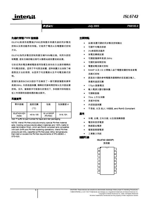
®1CAUTION: These devices are sensitive to electrostatic discharge; follow proper IC Handling Procedures.1-888-INTERSIL or 321-724-7143|Intersil (and design) is a registered trademark of Intersil Americas Inc.Copyright © Intersil Americas Inc. 2005. All Rights ReservedAll other trademarks mentioned are the property of their respective owners先進的雙端PWM 控制器ISL6742是高性能雙端(PWM)控制器并具備先進的同步整流控制以及限流臨界的特點。
它能用于電流以及電壓模式控制方法。
ISL6742為同步整流控制具備互補PWM輸出端。
利用外部控制電壓, 這些互補的輸出端可以動態地被前置或者延遲。
它的优秀的電流傳感電路使用取樣及保存的方法提供精确的平均電流信號。
适用于平均限流保護, 這种保護方法消除了峰值限流方法的局限, 也适用于均流電路以及平均電流模式控制。
這個先進的BiCMOS設計不但兼容了一個可調振蕩器其頻率高達2MHz, 內部過溫保護, 精确的死區時間控制以及共振延遲控制。
另外, 當跳脈沖可能發生的情況下, 多相脈沖抑制能在低工作周期時保證相應的輸出脈沖。
定購資料零件號碼溫度范圍(°C)包裝 包装圖號 #ISL6742AAZA(Note)-40 to 10516 Ld QSOP (Pb-free)M16.15AAdd -T suffix to part number for tape and reel packaging.NOTE: Intersil Pb-free products employ special Pb-free material sets; molding compounds/die attach materials and 100% matte tin plate termination finish, which are RoHS compliant and compatible with both SnPb and Pb-free soldering operations. Intersil Pb-free products are MSL classified at Pb-free peak reflow temperatures that meet or exceed the Pb-free requirements of IPC/JEDEC J STD-020.主要特點• 延遲/前置可調的同步整流控制輸出 • 可調平均電流信號 • 3%峰值限流臨界 • 快電流傳感延遲• 可調振蕩頻率高達2MHz • 可調死區時間控制 • 電壓或電流模式控制• RAMP 以及CS 分開輸入益于電壓前饋控制或者電流模式控制• 誤差放大器的參考電壓具備精确的容差遍及輸入、負載和溫度范圍 • 175µA 啟動電流 •輸入電源欠壓切斷保護 • 可調軟啟動 •70ns 上升沿消隱 •多脈沖抑制 • 內部過溫保護•不含鉛, 以及ELV, WEEE, and RoHS Compliant應用• 半橋, 全橋, 正向交錯, 以及推挽轉換器 • 電信和信息電源 • 無線基站電源 • 檔案服務器電源 •工業動力系統插腳引線ISL6742 (QSOP)頂視圖OUTAN OUTBNOUTAOUTBIOUTCTRTDVDDGNDVREFVERRFBSSCSVADJRAMP內部電路結构典型應用電路 – 電信原邊半橋式同步整流轉換器VIN-典型應用電路 – 高壓輸入次邊控制ZVS全橋轉換器VIN-額定值Supply Voltage, VDD ----------------GND - 0.3V to +20.0V OUTxxx ------------------------------------GND - 0.3V to VDD Signal Pins-------------------------GND - 0.3V to V REF +0.3V VREF ---------------------------------------GND – 0.3V to 6.0V Peak GATE Current-----------------------------------------0.1A ESD ClassificationHuman Body Model (Per MIL-STD-883 Method 3015.7)------2000V Charged Device Model (Per EOS/ESD DS5.3, 4/14/93)-------1000V 運行條件Supply Voltage Range (Typical)------------------9V-16VDC Temperature RangeISL6742AAxx-------------------------------40o C to 105o C 熱性能的資料Thermal Resistance Junction to Ambient (Typical) θJA (o C/W) 16 Lead QSOP (Note 1)-------------------------------------95 Maximum Junction Temperature -------------------55o C to 150o C Maximum Storage Temperature Range-----------65o C to 150o C Maximum Lead Temperature (Soldering 10s)--------------300o C (QSOP – Lead Tips Only)CAUTION: Stress above those listed in “Absolute Maximum Ratings” may cause permanent damage to the device. This is a stress only rating and operation of thedevice at these or any other conditions above those indicated in the operational section of this specification is not implied.Notes:1) θJA is measured with the component mounted on a low effective thermal conductivity test board in free air. See Tech Brief TB379 fordetails.2) All voltages are with respect to GND.Electrical SpecificationsRecommended Operating Conditions, Unless Otherwise Noted. Refer to Block Diagram and Typical Application Schematic.9V < V DD < 20V, RTD = 10.0kΩ, CT = 470pF, T A = -40o C to 105o C (Note 3), Typical values are at T A= 25o C.PARAMETER TESTCONDITIONSMINTYPMAXUNITS SUPPLY VOLTAGESupply Voltage - - 20 VStart-Up Current, I DD VDD= 5.0V -175400µAOperating Current, I DD R LOAD, C OUT = 0 - 7.5 12 mAUVLO START Threshold 8 8.75 9 VUVLO STOP Threshold 6.5 7 7.5 VHysteresis - 1.75 - VREFERENCE VOLTAGEOverall Accuracy I VREF = 0 - 10mA 4.85 5 5.15 VLong Term Stability TA = 125°C, 1000 hours (Note 4) - 3 - mVOperational Current (source) -10 - - mAOperational Current (sink) 5 - - mACurrent Limit VREF = 4.85V -15 - -100 mACURRENT SENSECurrent Limit Threshold VERR = VREF 0.97 1 1.03 VCS to OUT Delay Excl. LEB (Note 4) - 35 50 nsLeading Edge Blanking (LEB) Duration (Note 4) 50 70 100 nsCS to OUT Delay + LEB T A = 25°C - - 130 nsCS Sink Current Device Impedance V CS = 1.1V - - 20 ΩInput Bias Current V CS = 0.3V -1.0 - 1.0 µA 電气規范Electrical Specifications電气規范Recommended Operating Conditions, Unless Otherwise Noted. Refer to Block Diagram and Typical Application Schematic.9V < V DD < 20V, RTD = 10.0kΩ, CT = 470pF, T A = -40o C to 105o C (Note 3), Typical values are at T A= 25o C. (continued)MAXTYPUNITS PARAMETER TESTCONDITIONSMINIOUT Sample and Hold Buffer AmplifierT A = 25°C 4 4.09 4.15 V/VGainIOUT Sample and Hold VOH V CS = 1.00V, I LOAD = -300µA 3.9 - - VIOUT Sample and Hold VOL V CS = 0.00V, I LOAD = 10µA - - 0.3 VRAMPRAMP Sink Current Device Impedance V RAMP = 1.1V - - 20 ΩRAMP to PWM Comparator Offset T A = 25°C 65 80 95 mVBias Current V RAMP = 0.3V -5 - -2 µAClamp Voltage (Note 4) 6.5 - 8 VSOFT-STARTCharging Current SS = 3V -60 -70 -80 µASS Clamp Voltage 4.41 4.5 4.59 VSS Discharge Current SS = 2V 10 - - mAReset Threshold Voltage T A = 25°C 0.23 0.27 0.33 VERROR AMPLIFIERInput Common Mode (CM) Range (Note 4) 0 - VREF VGBWP (NoteMHz-4) 5-VERR VOL I LOAD = 2mA - - 0.4 VVERR VOH I LOAD = 0mA 4.2 - - VVERR Pull-Up Current Source VERR = 2.50V 0.8 1 1.3 mAEA Reference TA = 25°C 0.594 0.6 0.606 VEA Reference + EA Input Offset Voltage 0.59 0.6 0.612 VPULSE WIDTH MODULATORMinimum Duty Cycle VERR < 0.6V - - 0 %VERR = 4.20V, V RAMP = 0V, V CS = 0V94 %(Note 5)Maximum Duty Cycle (per half-cycle)RTD = 2.00kΩ, CT = 220pF- 97 - %RTD = 2.00kΩ, CT = 470pF - 99 - %Zero Duty Cycle VERR Voltage 0.85 - 1.2 VVERR to PWM Comparator Input Offset T A = 25°C 0.7 0.8 0.9 VVERR to PWM Comparator Input Gain 0.31 0.33 0.35 V/VCommon Mode (CM) Input Range (Note 4) 0 - 4.45 VOSCILLATORFrequency Accuracy, Overall(Note 4) 165 183 201 kHz%10-10-%0.3Frequency Variation with VDD T A = 25°C, (F20V- - F10V)/F10V -1.7VDD = 10V, |F-40°C - F0°C|/F0°C- 4.5 - %Temperature Stability|F0°C – F105°C|/F25°C (Note 4) - 1.5 - %Electrical SpecificationsRecommended Operating Conditions, Unless Otherwise Noted. Refer to Block Diagram and Typical Application Schematic.9V < V DD < 20V, RTD = 10.0k Ω, CT = 470pF, T A = -40oC to 105oC (Note 3), Typical values are at T A = 25oC.Charge Current T A = 25°C, V CS = 1.8V -193 -200 -207 µA Discharge Current Gain19 21 23 µA/µA CT Valley Voltage Static Threshold 0.75 0.8 0.88 V CT Peak Voltage Static Threshold 2.75 2.8 2.88 V CT Pk-Pk Voltage Static Value 1.92 2 2.05 V RTD Voltage1.9722.03VOUTPUTHigh Level Output Voltage (VOH) I OUT = -10mA, VDD - VOH - 0.5 1 V Low Level Output Voltage (VOL) I OUT = 10mA, VOL - GND- 0.5 1 V Rise Time C OUT = 220pF, VDD = 15V (Note 4) - 110 200 ns Fall TimeC OUT = 220pF, VDD = 15V (Note 4) - 90 150 ns UVLO Output Voltage ClampVDD = 7V, I LOAD = 1mA (Note 6) - - 1.25 VV ADJ = 2.50V (Note 4) - - 3 ns V ADJ < 2.425V -40 - -300 nsOutput Delay/Advance RangeOUTAN/OUTBN relative to OUTA/OUTBV ADJ > 2.575V40 - 300 ns Delay Control Voltage RangeOUTAN/OUTBN relative to OUTA/OUTB OUTxN Delayed2.575-5VOUTx Delayed 0 - 2.425 VT A = 25°C (OUTx Delayed)VADJ = 0 280 300 320 ns VADJ = 0.5V 92 105 118 ns VADJ = 1.0V 61 70 80 ns VADJ = 1.5V 48 55 65 ns VADJ = 2.0V41 50 58 ns T A = 25°C (OUTxN Delayed) VADJ = VREF 280 300 320 ns VADJ = VREF - 0.5V 86 100 114 ns VADJ = VREF - 1.0V 59 68 77 ns VADJ = VREF - 1.5V 47 55 62 ns VADJ Delay TimeVADJ = VREF - 2.0V41 48 55 ns THERMAL PROTECTIONThermal Shutdown (Note 4) 130 140 150 °C Thermal Shutdown Clear (Note 4) 115 125 135 °C Hysteresis, Internal Protection (Note 4)-15-°CNOTES:3. Specifications at -40oC and 105 oC are guaranteed by 25 oC test with margin limits. 4. Guaranteed by design, not 100% tested in production.5. This is the maximum duty cycle achieveable using the specified values of RTD and CT. Larger or smaller maximum duty cycles may beobtained using other values for these components. See Equation 1-3. 6. Adjust VDD below the UVLO stop threshold prior to setting at 7V.電气規范各管腳簡介VDDVDD是控制器的電源輸入端。

®X9C102, X9C103, X9C104, X9C503Digitally Controlled Potentiometer (XDCP™)FEATURES•Solid-state potentiometer•3-wire serial interface•100 wiper tap points—Wiper position stored in nonvolatile memory and recalled on power-up•99 resistive elements—Temperature compensated—End to end resistance, ±20%—Terminal voltages, ±5V•Low power CMOS—V CC = 5V—Active current, 3mA max.—Standby current, 750µA max.•High reliability—Endurance, 100,000 data changes per bit —Register data retention, 100 years•X9C102 = 1kΩ•X9C103 = 10kΩ•X9C503 = 50kΩ•X9C104 = 100kΩ•Packages—8 Ld SOIC and 8 Ld PDIP•Pb-free plus anneal available (RoHS compliant)DESCRIPTIONThe X9Cxxx are Intersil digitally controlled (XDCP) potentiometers. The device consists of a resistor array, wiper switches, a control section, and nonvola-tile memory. The wiper position is controlled by a three-wire interface.The potentiometer is implemented by a resistor array composed of 99 resistive elements and a wiper switch-ing network. Between each element and at either end are tap points accessible to the wiper terminal. The position of the wiper element is controlled by the CS, U/D, and INC inputs. The position of the wiper can be stored in nonvolatile memory and then be recalled upon a subsequent power-up operation.The device can be used as a three-terminal potentiom-eter or as a two-terminal variable resistor in a wide variety of applications including:–control–parameter adjustments–signal processingBLOCK DIAGRAMDeviceSSGeneralDetailed L/V L W/V W H/V HH/R HW/VL/R L SelectPIN DESCRIPTIONS Pin Symbol Brief Description1INC Increment . The INC input is negative-edge triggered. Toggling INC will move the wiper and either increment or decrement the counter in the direction indicated by the logic level on the U/D input.2U/D Up/Down. The U/D input controls the direction of the wiper movement and whether the counter is incremented or decremented.3R H /V HR H /V H . The high (V H /R H ) terminals of the X9C102/103/104/503 are equivalent to the fixedterminals of a mechanical potentiometer. The minimum voltage is -5V and the maximum is +5V. The terminology of V H /R H and V L /R L references the relative position of the terminal inrelation to wiper movement direction selected by the U/D input and not the voltage potential on the terminal.4V SS V SS5V W /R W V W /R W . V W /R W is the wiper terminal, and is equivalent to the movable terminal of a mechanical potentiometer. The position of the wiper within the array is determined by the control inputs. The wiper terminal series resistance is typically 40Ω.6R L /V LR L /V L . The low (V L /R L ) terminals of the X9C102/103/104/503 are equivalent to the fixedterminals of a mechanical potentiometer. The minimum voltage is -5V and the maximum is +5V. The terminology of V H /R H and V L /R L references the relative position of the terminal inrelation to wiper movement direction selected by the U/D input and not the voltage potential on the terminal.7CSCS. The device is selected when the CS input is LOW. The current counter value is stored innonvolatile memory when CS is returned HIGH while the INC input is also HIGH. After the store op-eration is complete the X9C102/103/104/503 device will be placed in the low power standby mode until the device is selected once again.8V CCV CCABSOLUTE MAXIMUM RATINGSTemperature under bias....................-65°C to +135°C Storage temperature.........................-65°C to +150°C Voltage on CS, INC, U/D and V CCwith respect to V SS ..................................-1V to +7V Voltage on V H /R H and V L /R Lreferenced to V SS ...................................-8V to +8V ΔV = |V H /R H - V L /R L |X9C102 ...............................................................4V X9C103, X9C503, and X9C104.........................10V Lead temperature (soldering, 10 seconds)......+300°C I W (10 seconds).................................................8.8mA Power rating X9C102........................................16mW Power rating X9C103/104/503..........................10mWCOMMENT Stresses above those listed under “Absolute Maximum Ratings” may cause permanent damage to the device.This is a stress rating only; functional operation of the device (at these or any other conditions above those listed in the operational sections of this specification) is not implied. Exposure to absolute maximum rating conditions for extended periods may affect device reliability.POTENTIOMETER CHARACTERISTICS (Over recommended operating conditions unless otherwise stated.)Notes:(1)Absolute linearity is utilized to determine actual wiper voltage versus expected voltage = [V W(n)(actual) - V W(n)(expected )] = ±1 MI Maximum. (2)Relative linearity is a measure of the error in step size between taps = V W(n + 1) - [V W(n) + MI ] = +0.2 MI.(3) 1 MI = Minimum Increment = R TOT /99(4)Typical values are for T A = +25°C and nominal supply voltage.(5)This parameter is not 100% tested.Symbol ParameterLimitsUnit Test Conditions/NotesMin.Typ.Max.R TOTAL End to end resistance variation -20+20%V VH/RH V H terminal voltage -5+5V V VL/RL V L terminal voltage -5+5V I W Wiper current -4.44.4mA R WWiper resistance 40100ΩWiper Current = ±1mA Noise (5)-120dBV Ref. 1kHzResolution 1%Absolute linearity (1)-1+1MI (3)V W(n)(actual) - V W(n)(expected)Relative linearity (2)-0.2+0.2MI (3)V W(n + 1)(actual) - [V W(n)+MI ]RTOTAL temperature coefficient ±300(5)ppm/°C X9C103/503/104RTOTAL temperature coefficient ±600(5)ppm/°C X9C102Ratiometric temperature coefficient±20ppm/°C C H /C L /C W(5)Potentiometer capacitances10/10/25pFSee Circuit #3, Macro ModelRECOMMENDED OPERATING CONDITIONS Temperature mercial 0°C +70°C Industrial-40°C+85°CSupply Voltage (V CC )Limits X9C102/103/104/5035V ±10%ENDURANCE AND DATA RETENTIONA.C. CONDITIONS OF TEST Symbol ParameterLimitsUnit Test ConditionsMin.Typ.(4)Max.I CC V CC active current 13mA CS = V IL , U/D = V IL or V IH and INC=****************CYC I SB Standby supply current 200750µA CS = V CC - 0.3V, U/D and INC = V SS or V CC -0.3V I LI CS, INC, U/D input leakage current±10µA V IN = V SS to V CCV IH CS, INC, U/D input HIGH voltage2VV IL CS, INC, U/D input LOW voltage0.8V C IN (5)CS, INC, U/D input capacitance10pFV CC = 5V, V IN = V SS , T A = 25°C, f = 1MHzParameter Min.UnitMinimum endurance 100,000Data changes per bit per registerData retention100yearsInput pulse levels 0V to 3V Input rise and fall times 10ns Input reference levels1.5VTest Circuit #1Test Circuit #2Test Circuit #3Test Point V W /R W V R /R HV SV L /R LForce Current V H /R HTest PointV W /R WV L /R LR HC H10pFC W R LC LR WR TOTAL25pF10pFMacro ModelPOWER-UP AND DOWN REQUIREMENTSAt all times, voltages on the potentiometer pins must be less than ±V CC . The recall of the wiper position from nonvola-tile memory is not in effect until the V CC supply reaches its final value. The V CC ramp rate spec is always in effect.A.C. TIMINGNotes:(6)Typical values are for T A = 25°C and nominal supply voltage.(7) This parameter is periodically sampled and not 100% tested.(8)MI in the A.C. timing diagram refers to the minimum incremental change in the V W output due to a change in the wiper position.Symbol ParameterLimitsUnit Min.Typ.(6)Max.t Cl CS to INC setup100ns t lD INC HIGH to U/D change 100ns t DI U/D to INC setup 2.9µs t lL INC LOW period 1µs t lH INC HIGH period1µs t lC INC inactive to CS inactive 1µs t CPH CS deselect time (STORE)20ms t CPH CS deselect time (NO STORE)100ns t IW (5)INC to V W/RW change 100µs t CYC INC cycle time2µs t R , t F (5)INC input rise and fall time 500µs t PU (5)Power-up to wiper stable 500µs t R V CC (5)V CC power-up rate0.250V/msCSINCU/DV Wt CIt ILt IHt CYCt IDt DIt IWMI(8)t ICt CPHt Ft R10%90%90%DETAILED PIN DESCRIPTIONS R H /V H and R L /V LThe high (V H /R H ) and low (V L /R L ) terminals of the X9C102/103/104/503 are equivalent to the fixed termi-nals of a mechanical potentiometer. The minimum voltage is -5V and the maximum is +5V. The terminol-ogy of V H /R H and V L /R L references the relative position of the terminal in relation to wiper movement direction selected by the U/D input and not the voltage potential on the terminal.R W /V WV W /R W is the wiper terminal, and is equivalent to the movable terminal of a mechanical potentiometer. The position of the wiper within the array is determined by the control inputs. The wiper terminal series resistance is typically 40Ω.Up/Down (U/D)The U/D input controls the direction of the wiper move-ment and whether the counter is incremented or dec-remented.Increment (INC)The INC input is negative-edge triggered. Toggling INC will move the wiper and either increment or decre-ment the counter in the direction indicated by the logic level on the U/D input.Chip Select (CS)The device is selected when the CS input is LOW.The current counter value is stored in nonvolatile memory when CS is returned HIGH while the INC input is also HIGH. After the store operation is com-plete the X9C102/103/104/503 device will be placed in the low power standby mode until the device is selected once again.PIN CONFIGURATIONPIN NAMESPRINCIPLES OF OPERATIONThere are three sections of the X9Cxxx: the input con-trol, counter and decode section; the nonvolatile mem-ory; and the resistor array. The input control section operates just like an up/down counter. The output of this counter is decoded to turn on a single electronic switch connecting a point on the resistor array to the wiper output. Under the proper conditions the contents of the counter can be stored in nonvolatile memory and retained for future use. The resistor array is com-prised of 99 individual resistors connected in series. At either end of the array and between each resistor is an electronic switch that transfers the potential at that point to the wiper.The wiper, when at either fixed terminal, acts like its mechanical equivalent and does not move beyond the last position. That is, the counter does not wrap around when clocked to either extreme.The electronic switches on the device operate in a “make before break” mode when the wiper changes tap positions. If the wiper is moved several positions,multiple taps are connected to the wiper for t IW (INC to V W /R W change). The R TOTAL value for the device can temporarily be reduced by a significant amount if the wiper is moved several positions.When the device is powered-down, the last wiper posi-tion stored will be maintained in the nonvolatile mem-ory. When power is restored, the contents of the memory are recalled and the wiper is set to the value last stored.V CC CS V L /R L V W /R WINC U/D V SS12348765V H /R H X9C102/103/104/503DIP/SOICSymbol DescriptionV H /R H High Terminal V W /R W Wiper Terminal V L /R L Low Terminal V SS Ground V CC Supply Voltage U/D Up/Down Control Input INC Increment Control Input CS Chip Select Control Input NCNo ConnectionINSTRUCTIONS AND PROGRAMMINGThe INC, U/D and CS inputs control the movement of the wiper along the resistor array. With CS set LOW the device is selected and enabled to respond to the U/D and INC inputs. HIGH to LOW transitions on INC will increment or decrement (depending on the state of the U/D input) a seven-bit counter. The output of this counter is decoded to select one of one-hundred wiper positions along the resistive array.The value of the counter is stored in nonvolatile mem-ory whenever CS transitions HIGH while the INC input is also HIGH.The system may select the X9Cxxx, move the wiper, and deselect the device without having to store the lat-est wiper position in nonvolatile memory. After the wiper movement is performed as described above and once the new position is reached, the system must keep INC LOW while taking CS HIGH. The new wiper position will be maintained until changed by the sys-tem or until a power-down/up cycle recalled the previ-ously stored data.This procedure allows the system to always power-up to a preset value stored in nonvolatile memory; then during system operation minor adjustments could be made. The adjustments might be based on user pref-erence: system parameter changes due to tempera-ture drift, etc...The state of U/D may be changed while CS remains LOW. This allows the host system to enable the device and then move the wiper up and down until the proper trim is attained.MODE SELECTIONSYMBOL TABLECS INC U/D ModeL H Wiper UpL L Wiper DownH X Store Wiper PositionH X X Standby CurrentL X No Store, Return to StandbyL H Wiper Up (not recommended)L L Wiper Down (not recommended)WAVEFORM INPUTS OUTPUTSMust besteadyWill besteadyMay changefrom Lo w toHighWill changefrom Lo w toHighMay changefrom High toLowWill changefrom High toLowDon’t Care:ChangesAllowedChanging:State NotKnownN/A Center Lineis HighImpedancePERFORMANCE CHARACTERISTICSContact the factory for more information.APPLICATIONS INFORMATIONElectronic digitally controlled (XCDP) potentiometers provide three powerful application advantages; (1) the variability and reliability of a solid-state potentiometer, (2) the flexibility of computer-based digital controls, and (3) the retentivity of nonvolatile memory used for the storage of multiple potentiometer settings or data.Basic Configurations of Electronic PotentiometersV RBasic CircuitsX9C102, X9C103, X9C104, X9C503Small Outline Package Family (SO)GAUGE PLANEA2A1LL1DETAIL X4° ±4°SEATING PLANEeHbC0.010BM C A 0.004C0.010BM C A BD(N/2)1E1EN(N/2)+1APIN #1I.D. MARKh X 45°ASEE DETAIL “X”c0.010MDP0027SMALL OUTLINE PACKAGE FAMILY (SO)SYMBOLSO-8SO-14SO16 (0.150”)SO16 (0.300”) (SOL-16)SO20 (SOL-20)SO24 (SOL-24)SO28 (SOL-28)TOLERANCENOTESA 0.0680.0680.0680.1040.1040.1040.104MAX -A10.0060.0060.0060.0070.0070.0070.007±0.003-A20.0570.0570.0570.0920.0920.0920.092±0.002-b 0.0170.0170.0170.0170.0170.0170.017±0.003-c 0.0090.0090.0090.0110.0110.0110.011±0.001-D 0.1930.3410.3900.4060.5040.6060.704±0.0041, 3E 0.2360.2360.2360.4060.4060.4060.406±0.008-E10.1540.1540.1540.2950.2950.2950.295±0.0042, 3e 0.0500.0500.0500.0500.0500.0500.050Basic -L 0.0250.0250.0250.0300.0300.0300.030±0.009-L10.0410.0410.0410.0560.0560.0560.056Basic -h 0.0130.0130.0130.0200.0200.0200.020Reference -N 8141616202428Reference-Rev. L 2/01NOTES:1.Plastic or metal protrusions of 0.006” maximum per side are not included.2.Plastic interlead protrusions of 0.010” maximum per side are not included.3.Dimensions “D” and “E1” are measured at Datum Plane “H”.4.Dimensioning and tolerancing per ASME Y14.5M -199411All Intersil U.S. products are manufactured, assembled and tested utilizing ISO9000 quality systems.Intersil Corporation’s quality certifications can be viewed at /design/qualityIntersil products are sold by description only. Intersil Corporation reserves the right to make changes in circuit design, software and/or specifications at any time without notice. Accordingly, the reader is cautioned to verify that data sheets are current before placing orders. Information furnished by Intersil is believed to be accurate and reliable. However, no responsibility is assumed by Intersil or its subsidiaries for its use; nor for any infringements of patents or other rights of third parties which may result from its use. No license is granted by implication or otherwise under any patent or patent rights of Intersil or its subsidiaries.For information regarding Intersil Corporation and its products, see FN8222.1December 20, 2006X9C102, X9C103, X9C104, X9C503Plastic Dual-In-Line Packages (PDIP)MDP0031PLASTIC DUAL-IN-LINE PACKAGESYMBOLPDIP8PDIP14PDIP16PDIP18PDIP20TOLERANCENOTESA 0.2100.2100.2100.2100.210MAX A10.0150.0150.0150.0150.015MIN A20.1300.1300.1300.1300.130±0.005b 0.0180.0180.0180.0180.018±0.002b20.0600.0600.0600.0600.060+0.010/-0.015c 0.0100.0100.0100.0100.010+0.004/-0.002D 0.3750.7500.7500.890 1.020±0.0101E 0.3100.3100.3100.3100.310+0.015/-0.010E10.2500.2500.2500.2500.250±0.0052e 0.1000.1000.1000.1000.100Basic eA 0.3000.3000.3000.3000.300Basic eB 0.3450.3450.3450.3450.345±0.025L 0.1250.1250.1250.1250.125±0.010N814161820ReferenceRev. B 2/99NOTES:1.Plastic or metal protrusions of 0.010” maximum per side are not included.2.Plastic interlead protrusions of 0.010” maximum per side are not included.3.Dimensions E and eA are measured with the leads constrained perpendicular to the seating plane.4.Dimension eB is measured with the lead tips unconstrained.5.8 and 16 lead packages have half end-leads as shown.DAebA1NOTE 5A2SEATING PLANELNPIN #1INDEXE112N/2b2EeBeA c。

抗辐射美国Intersil公司推出耐辐射塑料封装集成电路产品,支持低轨道小卫星任务美国Intersil公司宣布推出其全新的三款耐辐射塑料封装IC系列产品,旨在支持快速发展的低地球轨道(LEO)小型卫星任务。
Intersil的耐辐射塑料器件包括ISL71026M 3.3V控制器局域网(CAN)收发器,ISL71444M 40V四路精密轨到轨输入输出(RRIO)运算放大器和ISL71001M 6A负载点(POL)电压调节器。
这些器件的成本远低于Class V空间级产品的。
所有三个ISL71xxxM器件都通过了测试,总剂量(TID)高达30krads(Si)。
单粒子事件(SEE)在线性能量转移(LET)为43MeV·cm2/mg的情况下未发生单粒子烧毁(SEB)、单粒子闩锁(SEL)、单粒子瞬变(SET)和单粒子功能中断(SEFI)。
塑料封装意义Intersil公司基于50多年的抗辐射产品(>75krad)和耐辐射产品(<75krad)研制经验,研发出耐辐射塑料封装流程。
前期的辐射效应表征和AEC-Q100汽车级鉴定降低了Intersil的耐辐射塑料器件成本,可用于成本敏感的小型卫星,支持卫星在LEO任务寿命长达五年。
ISL71xxxM还适用于高空(>40km)航空电子系统、易产生重离子的运载火箭,以及可能受辐射的医疗设备。
Intersil工业模拟和功率产品业务副总裁Philip Chesley表示:“低地球轨道的小型卫星使命寿命短,正在推动低成本的商业现货(COTS)IC发展,但仍旧存在昂贵的元器件升级筛选和宇航可靠性问题。
Intersil的具有成本效益、耐辐射塑料封装IC产品克服了COTS的可靠性问题和隐藏成本,为卫星制造商制造大型卫星星座群提供了保证。
”ISL71026MISL71026M耐辐射3.3V控制器局域网(CAN)收发器的串行数据传输速率高达1Mbps。
单个CAN总线可以连接的收发器多大120个,以减少卫星指令和遥测系统的尺寸、重量和功率(SWAP)成本。
FN2921Rev 12.00October 18, 2013HA-5002110MHz, High Slew Rate, High Output Current BufferDATASHEETThe HA-5002 is a monolithic, wideband, high slew rate, high output current, buffer amplifier.Utilizing the advantages of the Intersil D.I. technologies, the HA-5002 current buffer offers 1300V/μs slew rate with110MHz of bandwidth. The ±200mA output current capability is enhanced by a 3Ω output impedance.The monolithic HA-5002 will replace the hybrid LH0002 with corresponding performance increases. These characteristics range from the 3000k Ω input impedance to the increased output voltage swing. Monolithic design technologies have allowed a more precise buffer to be developed with more than an order of magnitude smaller gain error.The HA-5002 will provide many present hybrid users with a higher degree of reliability and at the same time increase overall circuit performance.For the military grade product, refer to the HA-5002/883 datasheet.Features•Voltage gain. . . . . . . . . . . . . . . . . . . . . . . . . . . . . . . 0.995•High input impedance . . . . . . . . . . . . . . . . . . . . . .3000k Ω•Low output impedance. . . . . . . . . . . . . . . . . . . . . . . . . 3Ω•Very high slew rate. . . . . . . . . . . . . . . . . . . . . . . 1300V/μs •Very wide bandwidth . . . . . . . . . . . . . . . . . . . . . . 110MHz •High output current . . . . . . . . . . . . . . . . . . . . . . . . . . ±200mA •Pulsed output current. . . . . . . . . . . . . . . . . . . . . . . 400mA •Monolithic construction•Pb-Free available (RoHS Compliant)Applications•Line driver •Data acquisition •110MHz buffer •Radar cable driver •High power current booster •High power current source •Sample and holds •Video productsOrdering InformationPART NUMBERPART MARKING TEMP.RANGE (°C)PACKAGEPKG.DWG. #HA2-5002-2HA2- 5002-2-55 to +1258 Pin Metal Can T8.C HA4P5002-5Z (Note 1)HA4P 5002-5Z 0 to +7520 Ld PLCC (Pb-free)N20.35HA9P5002-5Z (Note 1)5002 5Z 0 to +758 Ld SOIC (Pb-free)M8.15HA9P5002-9Z (Note 1)5002 9Z-40 to +858 Ld SOIC (Pb-free)M8.15NOTE:1.These Intersil Pb-free plastic packaged products employ special Pb-free material sets, molding compounds/die attach materials, and 100% matte tin plate plus anneal (e3 termination finish, which is RoHS compliant and compatible with both SnPb and Pb-free soldering operations). Intersil Pb-free products are MSL classified at Pb-free peak reflow temperatures that meet or exceed the Pb-free requirements of IPC/JEDEC J STD-020.PinoutsHA-5002 (8 LD SOIC) TOP VIEWHA-5002(20 LD PLCC)TOP VIEWHA-5002(8 PIN METAL CAN)TOP VIEWNOTE:Case Voltage = Floating1 2 3 48765OUTV2+NCV1-V1+ V2-NC IN1932201151617181491011121345678V2-NCNCNCNCNCINNCV1-NCV2+NCNCNCNCNCV1+NCOUTNCINV2-V2+OUTV1+NCV1-NC24613758Absolute Maximum Ratings Thermal InformationVoltage Between V+ and V- Terminals . . . . . . . . . . . . . . . . . . . 44V Input Voltage . . . . . . . . . . . . . . . . . . . . . . . . . . . . . . . . . . V1+ to V1-Output Current (Continuous) . . . . . . . . . . . . . . . . . . . . . . . . ±200mA Output Current (50ms On, 1s Off) . . . . . . . . . . . . . . . . . . . . ±400mA Operating ConditionsTemperature RangeHA-5002-2 . . . . . . . . . . . . . . . . . . . . . . . . . . . . . -55°C to +125°C HA-5002-5 . . . . . . . . . . . . . . . . . . . . . . . . . . . . . . . . 0°C to +75°C HA-5002-9 . . . . . . . . . . . . . . . . . . . . . . . . . . . . . . -40°C to +85°C Thermal ResistanceθJA (°C/W)θJC (°C/W) Metal Can Package (Notes 3, 4) . . . . .15567 PLCC Package (Note 3). . . . . . . . . . . .74N/A SOIC Package (Note 3). . . . . . . . . . . .157N/A Max Junction Temperature (Hermetic Packages, Note 2). . . . . +175°C Max Junction Temperature (Plastic Packages, Note 2). . . . . . . +150°C Max Storage Temperature Range. . . . . . . . . . . . . -65°C to +150°C Max Lead Temperature (Soldering 10s) . . . . . . . . . . . . . . . +300°C (PLCC and SOIC - Lead Tips Only)CAUTION: Do not operate at or near the maximum ratings listed for extended periods of time. Exposure to such conditions may adversely impact product reliability and result in failures not covered by warranty.2.Maximum power dissipation, including load conditions, must be designed to maintain the maximum junction temperature below +175°C for thecan packages, and below +150°C for the plastic packages.3.For θJA is measured with the component mounted on an evaluation PC board in free air.4.For θJC, the “case temp” location is the center of the exposed metal pad on the package underside.Electrical Specifications V SUPPLY = ±12V to ±15V, R S = 50Ω, R L = 1kΩ, C L = 10pF, Unless Otherwise SpecifiedPARAMETERTESTCONDITIONSTEMP(°C)HA-5002-2HA-5002-5, -9UNITSMIN TYP MAX MIN TYP MAXINPUT CHARACTERISTICSOffset Voltage25-520-520mVFull-1030-1030mV Average Offset Voltage Drift Full-30--30-μV/°C Bias Current25-27-27μAFull- 3.410- 2.410μA Input Resistance Full 1.53- 1.53-MΩInput Noise Voltage10Hz-1MHz25-18--18-μV P-P TRANSFER CHARACTERISTICSVoltage Gain (V OUT = ±10V)R L = 50Ω25-0.900--0.900-V/V R L = 100Ω25-0.971--0.971-V/V R L = 1kΩ25-0.995--0.995-V/V R L = 1kΩ Full0.980--0.980--V/V-3dB Bandwidth V IN = 1V P-P25-110--110-MHz AC Current Gain25-40--40-A/mA OUTPUT CHARACTERISTICSOutput Voltage Swing R L = 100Ω25±10±10.7-±10±11.2-VR L = 1kΩ, V S = ±15V Full±10±13.5-±10±13.9-VR L = 1kΩ, V S = ±12V Full±10±10.5-±10±10.5-V Output Current V IN = ±10V, R L = 40Ω25-220--220-mA Output Resistance Full-310-310ΩHarmonic Distortion V IN = 1V RMS, f = 10kHz25-<0.005--<0.005-% TRANSIENT RESPONSEFull Power Bandwidth (Note 5)25-20.7--20.7-MHz Rise Time25- 3.6-- 3.6-ns Propagation Delay25-2--2-ns Overshoot25-30--30-% Slew Rate25 1.0 1.3- 1.0 1.3-V/ns Settling Time To 0.1%25-50--50-ns Differential Gain R L = 500Ω25-0.06--0.06-% Differential Phase R L = 500Ω25-0.22--0.22-°POWER REQUIREMENTS Supply Current25-8.3--8.3-mA Full --10--10mA Power Supply Rejection Ratio A V = 10VFull5464-5464-dBNOTE:5..Electrical SpecificationsV SUPPLY = ±12V to ±15V, R S = 50Ω, R L = 1k Ω, C L = 10pF, Unless Otherwise Specified (Continued)PARAMETERTEST CONDITIONSTEMP (°C)HA-5002-2HA-5002-5, -9UNITSMINTYPMAXMINTYPMAXFPBW Slew Rate 2πV P EAK --------------------------;V P=10V =Test Circuit and WaveformsFIGURE RGE AND SMALL SIGNAL RESPONSESMALL SIGNAL WAVEFORMSSMALL SIGNAL WAVEFORMSLARGE SIGNAL WAVEFORMSLARGE SIGNAL WAVEFORMSOUTIN-15V+15VV 2+R SR LV 1+V 2-V 1-V OUTV IN R S = 50Ω, R L = 100ΩV OUTV INR S = 50Ω, R L = 1k ΩV OUT V INR S = 50Ω, R L = 100ΩV OUTV INR S = 50Ω, R L = 1k ΩSchematic DiagramApplication InformationLayout ConsiderationsThe wide bandwidth of the HA-5002 necessitates that high frequency circuit layout procedures be followed. Failure to follow these guidelines can result in marginal performance.Probably the most crucial of the RF/video layout rules is the use of a ground plane. A ground plane provides isolation and minimizes distributed circuit capacitance and inductance which will degrade high frequency performance.Other considerations are proper power supply bypassing and keeping the input and output connections as short as possible which minimizes distributed capacitance and reduces board space.Power Supply DecouplingFor optimal device performance, it is recommended that the positive and negative power supplies be bypassed withcapacitors to ground. Ceramic capacitors ranging in value from 0.01 to 0.1μF will minimize high frequency variations in supply voltage, while low frequency bypassing requires larger valued capacitors since the impedance of the capacitor is dependent on frequency.It is also recommended that the bypass capacitors be connected close to the HA-5002 (preferably directly to the supply pins).Operation at Reduced Supply LevelsThe HA-5002 can operate at supply voltage levels as low as ±5V and lower. Output swing is directly affected as well as slight reductions in slew rate and bandwidth.Short Circuit ProtectionThe output current can be limited by using the following circuit:Capacitive LoadingThe HA-5002 will drive large capacitive loads without oscillation but peak current limits should not be exceeded. Following the formula I = Cdv/dt implies that the slew rate or the capacitive load must be controlled to keep peak current below the maximum or use the current limiting approach as shown. The HA-5002 can become unstable with small capacitive loads (50pF) if certain precautions are not taken. Stability is enhanced by any one of the following: a source resistance in series with the input of 50Ω to 1k Ω; increasing capacitive load to 150pF or greater; decreasing C LOAD to 20pF or less; adding an output resistor of 10Ω to 50Ω; or adding feedback capacitance of 50pF or greater. Adding source resistance generally yields the best results.R 9R 10Q 25Q 9Q 10R 5Q 11Q 15Q 23R 7Q 21Q 22Q 24Q 27Q 26R 8Q 20Q 18Q 3R 4R 1Q 7Q 4Q 8R 6R 3R 12Q 16Q 14Q 13R 2R N3R 11Q 5Q 6Q 12R N1Q 19R N2V 1-V 2-OUTV 2+V 1+Q 1Q 2INQ 17OUTINV+R LIM R LIMV 1-V 2-V 2+V 1+V-I OUTMAX = 200mA(CONTINUOUS)R LIM V+I OUTMAX -------------------------V-I OUTMAX-------------------------==45105125TEMPERATURE (°C)M A X I M U M P O W E R D I S S I P A T I O N (W )Where:T JMAX = Maximum Junction Temperature of the Device T A = AmbientθJC = Junction to Case Thermal Resistance θCS = Case to Heat Sink Thermal Resistance θSA = Heat Sink to Ambient Thermal Resistance Graph is based on:P DMAX T JMAX T A–θJC θCS θSA++--------------------------------------------=P DMAX T JMAX T A–θJA-------------------------------=FIGURE 2. MAXIMUM POWER DISSIPATION vs TEMPERATURETypical ApplicationFIGURE 3.COAXIAL CABLE DRIVER - 50Ω SYSTEMR L 50ΩRG -5850ΩR M 50ΩR S V 1-V 2--12VV 1+V 2++12V V INV OUT V OUTV INTypical Performance CurvesFIGURE 4.GAIN/PHASE vs FREQUENCY (R L = 1k Ω)FIGURE 5.GAIN/PHASE vs FREQUENCY (R L = 50Ω)9630-3-18PHASEFREQUENCY (MHz)V O L T A G E G A I N (d B )V S = ±15V, R S = 50ΩGAIN-6-9-12-150°45°90°135°180°P H A S E S H I F T 1101009630-3-18PHASE110100FREQUENCY (MHz)V O L T A G E G A I N (d B )V S = ±15V, R S = 50ΩGAIN-6-9-12-150°45°90°135°180°P H A S E S H I F TFIGURE 6.VOLTAGE GAIN vs TEMPERATURE (R L = 100Ω)FIGURE 7.VOLTAGE GAIN vs TEMPERATURE (R L = 1k Ω)FIGURE 8.OFFSET VOLTAGE vs TEMPERATURE FIGURE 9.BIAS CURRENT vs TEMPERATUREFIGURE 10.MAXIMUM OUTPUT VOLTAGE vs TEMPERATURE FIGURE 11.SUPPLY CURRENT vs TEMPERATURETEMPERATURE (°C)0.9940.9920.9900.9880.9860.9840.9820.9800.9780.9760.974020406080100120-20-40-60V O L T A G E G A I N (V /V )V OUT = -10V TO +10VV S = ±15VTEMPERATURE (°C)0.9980.9970.9960.9950.9940.9930.9920.99120406080100120-20-40-60V O L T A G E G A I N (V /V )V OUT = 0 TO -10VV OUT = 0 TO +10VV S = ±15VTEMPERATURE (°C)020406080100120-20-40-60O F F S E T V O L T A G E (m V )3210-11-10-9-8-7-6-5-4-3-2-1V S = ±15VTEMPERATURE (°C)020406080100120-20-40-60B I A S C U R R E N T (μA )1234567V S = ±15V TEMPERATURE (°C)020406080100120-20-40-60O U T P U T V O L T A G E (V )1112131415+V OUTV S = ±15V, R LOAD = 100Ω-V OUTTEMPERATURE (°C)020406080100120-20-40-60S U P P L Y C U R R E N T (m A )368910754V S = ±15V, I OUT = 0mAFIGURE 12.SUPPLY CURRENT vs SUPPLY VOLTAGEFIGURE 13.INPUT/OUTPUT IMPEDANCE vs FREQUENCYFIGURE 14.V OUT MAXIMUM vs V SUPPLYFIGURE 15.PSRR vs FREQUENCYFIGURE 16.SLEW RATE vs SUPPLY VOLTAGE FIGURE 17.GAIN ERROR vs INPUT VOLTAGE24681012141618S U P P L Y C U R R E N T (m A )1086420SUPPLY VOLTAGE (±V)-55°C125°C, 25°CI OUT = 0mA100K 10K 1000100101Z OUT 100K1M 10M 100MFREQUENCY (Hz)Z INI M P E D A N C E (Ω)V S = ±15V151285T A = 25°C2322212019181716151413121110987V O U T M A X , V P -P A T 100k H zT A = -55°CT A = 125°C,SUPPLY VOLTAGE (±V)R LOAD = 100Ω10K100K1M10MFREQUENCY (Hz)P S R R (d B )80706050403020100100MS L E W R A T E (V /μs )150014001300120011001000900681012141618SUPPLY VOLTAGE (±V)T A = 25°CV S = ±15V R L = 600R L = 1K 150100500V O U T - V I N (m V )0246810INPUT VOLTAGE (VOLTS)-10-8-6-4-2-50-100-150R L = 100Intersil products are manufactured, assembled and tested utilizing ISO9001 quality systems as notedin the quality certifications found at /en/support/qualandreliability.htmlIntersil products are sold by description only. Intersil may modify the circuit design and/or specifications of products at any time without notice, provided that such modification does not, in Intersil's sole judgment, affect the form, fit or function of the product. Accordingly, the reader is cautioned to verify that datasheets are current before placing orders. Information furnished by Intersil is believed to be accurate and reliable. However, no responsibility is assumed by Intersil or its subsidiaries for its use; nor for any infringements of patents or other rights of third parties which may result from its use. No license is granted by implication or otherwise under any patent or patent rights of Intersil or its subsidiaries.For information regarding Intersil Corporation and its products, see For additional products, see /en/products.html© Copyright Intersil Americas LLC 2003-2013. All Rights Reserved.All trademarks and registered trademarks are the property of their respective owners.Die CharacteristicsSUBSTRATE POTENTIAL (POWERED UP):V 1-TRANSISTOR COUNT:27PROCESS:Bipolar Dielectric IsolationMetallization Mask LayoutHA-5002V 1-INOUTV 2+V 1+ (ALT)V 1- (ALT)V 2-V 1+Metal Can Packages (Can)NOTES:1.(All leads) Øb applies between L1 and L2. Øb1 applies between L2and 0.500 from the reference plane. Diameter is uncontrolled in L1and beyond 0.500 from the reference plane.2.Measured from maximum diameter of the product.3.α is the basic spacing from the centerline of the tab to terminal 1 and β is the basic spacing of each lead or lead position (N -1 places)from α, looking at the bottom of the package.4.N is the maximum number of terminal positions.5.Dimensioning and tolerancing per ANSI Y14.5M - 1982.6.Controlling dimension: INCH.ØbØD2Øek1kβØb1BASE ANDSEATING PLANE F QØD ØD1L1L2REFERENCE PLANEL AαA ANe 1C L21T8.C MIL-STD-1835 MACY1-X8 (A1)8 LEAD METAL CAN PACKAGESYMBOLINCHESMILLIMETERS NOTESMIN MAX MIN MAX A 0.1650.185 4.19 4.70-Øb 0.0160.0190.410.481Øb10.0160.0210.410.531Øb20.0160.0240.410.61-ØD 0.3350.3758.519.40-ØD10.3050.3357.758.51-ØD20.1100.1602.794.06-e 0.200 BSC 5.08 BSC -e10.100 BSC 2.54 BSC-F -0.040-1.02-k 0.0270.0340.690.86-k10.027 0.0450.69 1.142L 0.5000.75012.7019.051L1-0.050- 1.271L20.250- 6.35-1Q0.0100.0450.251.14-α45o BSC 45o BSC 3β45o BSC45o BSC3N884Rev. 0 5/18/94Plastic Leaded Chip Carrier Packages (PLCC)A1ASEATING PLANE0.020 (0.51)MIN VIEW “A”D2/E20.025 (0.64)0.045 (1.14)R0.042 (1.07)0.056 (1.42)0.050 (1.27) TPEE10.042 (1.07)0.048 (1.22)PIN (1) IDENTIFIERC LD1D0.020 (0.51) MAX 3 PLCS0.026 (0.66)0.032 (0.81)0.045 (1.14)MIN0.013 (0.33)0.021 (0.53)0.025 (0.64)MINVIEW “A” TYP .0.004 (0.10)C-C-D2/E2C LNOTES:1.Controlling dimension: INCH. Converted millimeter dimensions are not necessarily exact.2.Dimensions and tolerancing per ANSI Y14.5M-1982.3.Dimensions D1 and E1 do not include mold protrusions. Allowable mold protrusion is 0.010 inch (0.25mm) per side. Dimensions D1and E1 include mold mismatch and are measured at the extreme material condition at the body parting line.4.To be measured at seating plane contact point.5.Centerline to be determined where center leads exit plastic body.6.“N” is the number of terminal positions.-C-N20.35 (JEDEC MS-018AA ISSUE A)20 LEAD PLASTIC LEADED CHIP CARRIER PACKAGESYMBOLINCHESMILLIMETERS NOTESMIN MAX MIN MAX A 0.1650.180 4.20 4.57-A10.0900.120 2.29 3.04-D 0.3850.3959.7810.03-D10.3500.3568.899.043D20.1410.169 3.59 4.294, 5E 0.3850.3959.7810.03-E10.3500.3568.899.043E20.1410.1693.594.294, 5N20206Rev. 211/97Package Outline DrawingM8.158 LEAD NARROW BODY SMALL OUTLINE PLASTIC PACKAGE Rev 4, 1/12DETAIL "A"TOP VIEW-C-SEATING PLANE x 45°NOTES:1.Dimensioning and tolerancing per ANSI Y14.5M-1994.2.Package length does not include mold flash, protrusions or gate burrs. Mold flash, protrusion and gate burrs shall not exceed 0.15mm (0.006inch) per side.3.Package width does not include interlead flash or protrusions. Interlead flash and protrusions shall not exceed 0.25mm (0.010 inch) per side.4.The chamfer on the body is optional. If it is not present, a visual indexfeature must be located within the crosshatched area.5.Terminal numbers are shown for reference only.6.The lead width as measured 0.36mm (0.014 inch) or greater above theseating plane, shall not exceed a maximum value of 0.61mm (0.024 inch).7.Controlling dimension:MILLIMETER. Converted inch dimensions are not necessarily exact.8. This outline conforms to JEDEC publication MS-012-AA ISSUE C.SIDE VIEW “ASIDE VIEW “B”1.27 (0.050)0.50 (0.20)0.25 (0.01)5.00 (0.197)4.80 (0.189)1.75 (0.069)1.35 (0.053)0.25(0.010)0.10(0.004)0.51(0.020)0.33(0.013)8°0°0.25 (0.010)0.19 (0.008)1.27 (0.050)0.40 (0.016)1.27 (0.050)5.20(0.205)12345678TYPICAL RECOMMENDED LAND PATTERN2.20 (0.087)0.60 (0.023)。