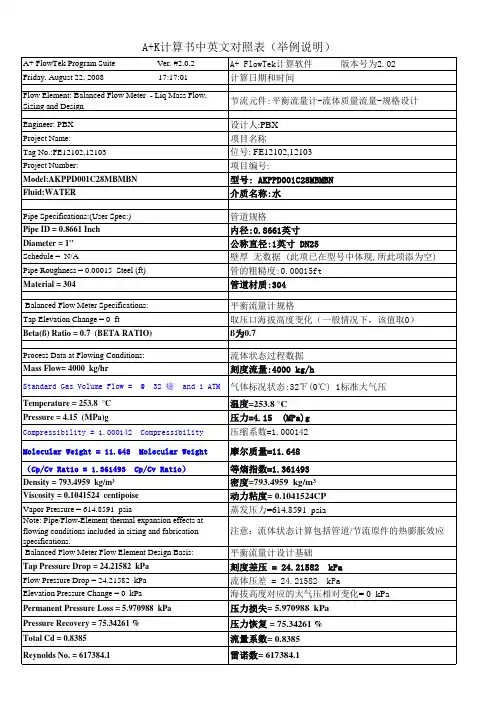
SAMPLE 平衡流量计
- 格式:pdf
- 大小:559.38 KB
- 文档页数:4
平衡流量计原理平衡流量计是一种常用的流体测量仪器,它通过测量流体通过管道时的压力差来确定流体的流量。
其原理是基于流体在管道内的运动特性和流体动能转化的关系,下面我们来详细了解一下平衡流量计的原理。
首先,平衡流量计的工作原理是基于伯努利方程和质量守恒定律的。
当流体在管道内流动时,流体的动能会随着流速的变化而发生改变。
根据伯努利方程,流速越大,动能越大,压力就越小;流速越小,动能越小,压力就越大。
平衡流量计利用这一原理,通过测量管道内两个位置的压力差来确定流体的流量。
其次,平衡流量计的原理还涉及到流体在管道内的流动特性。
当流体通过管道时,会受到管道壁面的阻力作用,这会导致流速的变化,从而影响流体的动能。
平衡流量计通过设计合理的结构和传感器,能够准确地测量流体通过管道时的压力差,从而确定流体的流量。
此外,平衡流量计的原理还与流体的密度有关。
根据质量守恒定律,流体在管道内的流量与流体的密度成正比。
平衡流量计在测量流体流量时,通常需要考虑流体的密度变化对测量结果的影响,以保证测量的准确性。
总的来说,平衡流量计的原理是基于伯努利方程、质量守恒定律以及流体在管道内的流动特性。
通过测量流体在管道内的压力差,结合流体的密度变化,可以准确地确定流体的流量。
这种原理使得平衡流量计在工业生产和科学研究中得到了广泛的应用,为流体测量提供了一种可靠的方法。
以上就是关于平衡流量计原理的详细介绍,希望能够帮助大家更好地理解这一流体测量仪器的工作原理。
平衡流量计作为一种重要的流量测量装置,在工业生产和科学研究中发挥着重要作用,相信随着技术的不断进步,它将会有更广泛的应用前景。
平衡流量计的工作原理引言平衡流量计是一种用于测量流体流量的仪器,多用于工业、制造业等领域。
平衡流量计能够精确地测量流体的流量,并适用于各种介质,如水、气体、油等。
工作原理平衡流量计的工作原理基于质量守恒定律和伯努利方程式。
伯努利方程式是描述理想流体运动规律的方程式,它描述了流体在定常条件下的能量守恒。
当流体通过平衡流量计时,根据伯努利方程式,在平衡流量计的两个测量点之间产生压差。
这个压差与流体的流量成正比。
平衡流量计通常由两个测量管组成,每个测量管都有一个流量管道。
在流体通过平衡流量计时,它将进入第一个测量管的流量管道中,并在管道中流动。
当流体到达第一个测量点时,它的流速会增加。
这会导致伯努利方程式中的压力降低,并产生一个压力下降。
流体继续通过第二个测量管道,到达第二个测量点时,它的流速又会增加。
这会导致伯努利方程式中的压力再次下降,并产生另一个压力下降。
平衡流量计的关键是通过测量这个压差来计算流体的流量。
当流体通过第一个测量点时,它的压力被测量,并通过一系列计算来计算流速。
当流体通过第二个测量点时,它的压力也被测量,并更新了流速计算。
最后,通过使用这些测量数据和伯努利方程式,可以计算出流体的流量。
平衡流量计的优缺点平衡流量计的优点在于它能够适用于各种介质,包括液体、气体和蒸汽等。
它还可以测量广泛的流量范围,并能够在不同的温度和压力下工作。
由于平衡流量计使用数字仪器进行测量,因此精度比传统的机械式计量器更高。
不过,平衡流量计也有其缺点。
首先,平衡流量计价格相对较高,而且需要比其他类型的流量计安装和维护成本较高。
此外,平衡流量计需要传感器和计算机系统进行测量,并且需要使用复杂的软件来计算流体的流量。
应用平衡流量计广泛应用于各种领域,例如食品加工、化学工业、石油和天然气开采、制药、电子、纺织和机械等领域。
在这些领域中,平衡流量计被用来测量和控制流体的流量,以确保生产过程的准确性和稳定性。
除了上述工业应用外,平衡流量计在医疗领域也有广泛的应用。
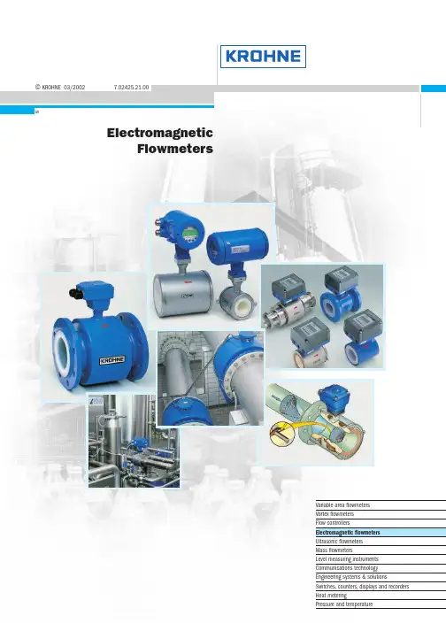
©KROHNE 03/20027.02425.21.00GRElectromagneticFlowmetersVariable area flowmetersVortex flowmetersFlow controllersElectromagnetic flowmetersUltrasonic flowmetersMass flowmetersLevel measuring instrumentsCommunications technologyEngineering systems & solutionsSwitches,counters,displays and recordersHeat meteringPressure and temperatureApplicationKROHNE electromagnetic flowmeters are to be found in many industrial sectors and applications.Just a small selection:G Chemical industry G Water and wastewaterGHydraulic transport,liquid products with up to 50% solids content G Paper and woodpulp production G Pharmaceutical G Food and beveragesG Filling and dispensing processes G Highly abrasive slurriesG High-pressure industrial processes GPartially filled pipelinesand many,many other applications in other industriesFIT and FORGET !All electromagnetic flowmeters are delivered ready for operation.Install the flowmeter in the pipeline,make the electrical connection,that's it.Always one step ahead with KROHNEThis highly accurate measurement technology is available with integrally or remote mounted converter,some with measuring errors of less than 0.2% of the measured value.The primary head is installed in the pipeline,while the signal converter for signal processing is remote mounted in a field housing or 19" plug-in unit.In the integral system,the signal converter is mounted in a housing with high protection category directly on the primary head.With meter sizes of DN2.5 - 3000 / 1/10" - 120",measurements can be carried out from 2l/h to 300 000m3/hand more.Most of the devices are approved for use in hazardous locations.Various materials are available for the measuring tube,liner and electrodes of the flowmeters for most applications. Electromagnetic flowmetersProduction and calibrationAll electromagnetic flowmeters from KROHNE meet the requirements of CE directives and EMC guidelines.Fabrication and production shops are certified to ISO 9001.At KROHNE,all electromagnetic flowmeters are calibrated by direct comparison of volumes,the most accurate calibration method of all.The KROHNE calibration rigs are the world's biggest and most accurate,and are accredited to EN17 025.Measurement uncertainty is less than 0.013% of themeasured value for meter sizes up to DN 3000 / 120" and above.7Electromagnetic flowmeters >0.05 µS /c m >5 µS /c m >20 µS /c m >50 µS /c mD N 2.5,4,6 1/10”,1/6”,1/4”D N 10 3/8”D N 32 11/2”Signal converterDatenblätterF l a n g e c o n n e c t i o n s F l a n g e l e s s ‘s a n d w i c h ’d e s i g n C h e m i c a l s W a t e r a n d s e w a g e P a r t i a l l y f i l l e d p i p e s P h a r m a c e u t i c a l s ,s a n i t a r y B a t c h i n g (1-10s )V e r y a b r a s i v e s l u r r i e s H i g h p r e s s u r e 2- o r 2 x 2-w i r e s y s t e mG e n e r a l p u r p o s e S a n i t a r y c o n n e c t i o n s H A R T ®/R S 485 (s t a n d a r d )P r o f i b u s P A H A R T ®/R S 485 (o p t i o n )H A R T ® (o p t i o n )O t h e r s o n r e q u e s t m Ao u t p u t ,2 w i r e c o n n e c t i o n ≤3 W ≤5 V A / ≤4.5 W ≤10 V A / ≤8 W ≤15 V A / ≤15 W ≤50 V A 2o r 2 x 2-w i r e s y s t e m 24,48,100 – 240 V A C ,48– 63 H z 24 V D C 24 V A C / D C 100 – 230 V A C ,48 –63 H z L i q u i d s ,p a s t e s S l u d g e a n d s l u r r i e s % s o l i d s /v o l u m e ≤3%S l u d g e a n d s l u r r i e s % s o l i d s /v o l u m e ≤5%S l u d g e a n d s l u r r i e s % s o l i d s /v o l u m e ≤30%P u l s a t i n g f l o w ,< 200 p u l s e s /m i n B a t c h i n g p r o c e s s > 1.5 s P a p e r a n d p u l p H y d r a u l i c t r a n s p o r t (o r e d r e s s i n g )o n l y I F C 090 K -C A P C a p a c i t i v e s i g n a l p i c k u p F ou n d a t i o n F i e l d B u s F A D N 251”D N 40 11/2”D N 502”D N 803”D N 1004”D N 1255”D N 1506”D N 2008”D N 25010”D N 30012”≤D N 1800≤72”≤D N 3000≤120”I S O f i t t i n g l e n g t h o n l y I F C 110 P F a n d I F C 210 E -P F P a r t i a l l y f i l l e d p i p e s ,AQUAFLUXECOFLUX 1000ALTOFLUX 2000ALTOFLUX 4000PROFIFLUX 5000VARIFLUX 6000ALTOFLUX 2W 2 wireBATCHFLUXCAPAFLUXTIDALFLUX partially filledALTOFLUX IFS 2005 FALTOFLUX IFS 4005 FALTOFLUX M 900IFC 010 K,FIFC 020 K,F ,EIFC 040 K 2 wireIFC 090 K,F IFC 090 K-CAP IFC 110 F IFC 110 PFIFC 210 E IFC 210 E-PFSC 150 FBatchflux IFC 012 KElectrical conductivitySizesConnectionsApplications (examples)Flow measurements (examples)Power supply Power consuptionInterfacesIFM 1080 KG Flangeless versionG Rugged measuring tube withstainless steel reinforced 080 KG Flanged connectionsG Steel housingµP-signal converter in plasticsIFM 4080 KG Flanged connectionsG Steel housingTeflon® PFA liner,reinforced withIFM 5080 KG Flangeless versionG Stainless steel housing The only precision flowmeter IFM 6080 KG Various sanitary/flangedconnectionsStainless steel housingG Precision flowmeterG With capacitive signal pickup(electrodes not in contact withG Flangeless versionG Rugged measuring tube withstainless steel reinforced G Flanged connectionsG Steel housingG Liner of Polypropylene,NSF-G Flanged connectionsG Steel housingG Teflon® PFA liner,reinforced withG Flangeless (sandwich) designG Stainless steel housingG The only precision flowmeter with G Flanged connectionsG Steel housingG Measuring tube made of Al2O3G Various sanitary/flanged connec-tions,stainless steel housingG FDA approved Teflon® PFA liner,G Designed for partially filled pipelinesG Excellent measuring accuracy,for low levels,through the integratedG IFC 010 K/IFC 020 K of integral design G IFC 010 F/IFC 020 F in field housing G IFC 020 E 19”plug-in version.G IFC 090 K of integral designG IFC 090 F in field housingG Signal processing by microprocessor,G Signal converter in field housingG Signal processing by microprocessor,outstanding interference rejection,G Signal converter in field housing for wall mounting G Signal processing by microprocessor,outstanding interference rejection,T o w e r h e i g h t 43 m e q u i v a l e n t t o 141 f t / n e t v o l u m e 350000 l i t r e s e q u i v a l e n t t o 95000 U S G a lPrecisionLM28 precision level switches control the flow volume and various computer-aided volume totalizersQmInlet run ≥10 ×DN (DN = meter size)©G The world’s largest and most accurate calibration rigGCalibration of flowmeters up to DN 3000 / 120”GCalibration by direct comparison of volumes,altogether the most accurate method GComparison measurements with so-called master meters are much less accurate and cannot be verifiedGThe volume measurement standards ofKROHNE calibration rigs have been calibrated by NMI,the Netherlands Standards Institute.Measurement uncertainty is less than 0.013% of the measured value.GKROHNE Altometer calibration rigs are accredited in conformity with EN 17 025.GCalibration accuracy is better than 99.97% of the measured value.GThe error of measurement of the calibration rigs is better by a factor of 10 than theaccuracy data of the flowmeter being tested.GAll flowmeters are calibrated underreference conditions,similar to EN 29 104.GAll calibration data are genuine and verifiable; documented in writing in the calibration reports,which are supplied together with each KROHNE flowmeter.An example is shown on the right.E r r o r o f m e a s u r e m e n t [% o f m e a s u r e d v a l u e ]Flow rate [m 3/h]0,50,402000400060008000100000,30,20,10,0-0,1-0,2-0,3-0,4-0,5+ 0.03%Accuracy inspires confidenceAt this flowrate,a typical public swimming-pool can be filled in less than 1 minute.Inaccuracy is less than 0.013% in terms of volume and less than 0.26 mm in terms of filling level (equal to the thickness of a single hair),based on an average pool depth of 2 metres.Flowmeters up to DN 3000/120”creates theKROHNE standardOutlet run ≥2 ×DN (DN =meter size)Volume flow rate Q max = 40 000 m 3/h= 11 m 3/sMeasuring Principle 3.1The induced voltage signal is picked up either by two measuring elec-trodes in conductive contact with the medium or indirectly bycapacitive coupling.A signal converter amplifies the signal and convertsit into a standard analog signal (e.g.4 to 20 mA) and a frequencysignal (e.g.1 pulse for every US gallon or cubic metre of mediumflowing through the measuring tube).To ensure that the voltage is not short-circuited by the pipe wall,themeasuring tube is made of an electrically insulating material or fittedwith an insulating liner.Measurement is largely independent of the flow profile and other prop-erties of the medium,such as pressure,temperature,viscosity,density,consistency,electrical conductivity,and electrode contamination.Measuring systemsThe electromagnetic flowmeter consists of a primary head,that isinstalled in the pipeline,and a signal converter.The compact design has the signal converter mounted directly on theprimary head.For systems with pulsed d.c.field the primary head field coils whichgenerate the magnetic field are energized by a pulsed direct currentfrom the signal converter.The measuring signal is a squarewave voltage of the same frequency.These systems feature extremely small measuring errors. Electromagnetic flowmeters measure the volume flow of electricallyconductive liquids and slurries.Measuring principleAn electric conductor,in this case the electrically conductive medium,passes through a magnetic field.The voltage U induced in this mediumis directly proportional to the mean flow velocity v.Magnetic inductionB (magnetic field strength) and the distance between electrodes D(nominal pipe diameter) are constant.K instrument constantB magnetic field strengthv mean flow velocityD electrode spacingThe volumetric flow rate qv can be calculated according toTherefore:q v=U x D xπ(4)K x B4The reducing angle (α) should not exceed 8°(equivalent to α/2 = 4°),otherwise measuring accuracy may be affected.If the reducing angle is greater,a straight inlet section must be fitted between reducing socket and primary head.Expanding sectionPressure Loss CalculationFor the expanding section,the optimum angle of expansion is α= 8°.ζat α= 8°d1/d2 1.2 1.3 1.4 1.5 1.6 1.7 1.8 1.9 2.0ζ10.0180.0230.02550.0280.030.03080.03150.03230.0332Recommendations for installationSelection of meter sizeThe size of primary head should if possible be selected to provide a velocity of 2 to 3m/s or 6 to 9ft/sec.for the full-scale range. Minimum full-scale range is 0.5m/s or 1.5ft/sec.,maximum is 10 or 11m/s or 30 or 33ft/sec.,depending on flowmeter type.For fluids with a solids content,the velocity should be between 3 and 5m/s or 9 and 15ft/s to prevent deposits and minimize abrasion.Exact determination of flow velocityFor range setting purposes,the exact flow velocity can be determined using the flow table for each nominal pipe width.Example: v in m/sNominal pipe diameter DN150Desired measuring range200m3/hFrom the table we obtain for the flow velocity of 1m/sa flow rate of 63.617m3/h at DN150; for 200m3/hthe flow velocity v is:Example: v in ft/sNominal pipe diameter6”Desired measuring range1000 US GPMFrom the table we obtain for the flow velocity of 1ft/sa flow rate of 88.128 US GPM at 6”meter size;for 1000 US GPM the flow velocity v is:Flow tablesv = 1m/sMeter size Flow rate Meter size Flow rate DN mm m3/h DN mm m3/h2.50.017671250176.71 40.0452********.47 60.10179350346.36 100.28274400452.39 150.63617500706.86 20 1.131********.9 25 1.76717001385.4 32 2.89538001809.6 40 4.52399002209.2 507.068610002827.4 6511.94612004071.5 8018.09614005541.8 10028.27416007238.2 12544.17918009160.9 15063.617200011310 200113.10v = 1ft/sMeter size Flow rate Meter size Flow rate inch US GMP inch US GMP1/100.024********.801/80.03825012352.511/40.1530014479.813/80.3442516626.69 1/20.6120020979.21 3/4 1.3770241410.1 1 2.4480281919.211/4 3.8250322506.8 11/2 5.5080363172.6 29.7921403916.8 21/215.300485640.2 322.032567677.0 439.1686410027 561.2007212691 688.1288015667 8156.67Protection classes to IEC 529/EN 60529。
本工程为平衡流量计安装施工项目,主要涉及平衡流量计的选型、安装、调试及验收等环节。
平衡流量计是一种测量流体流量的仪表,广泛应用于石油、化工、电力、环保等行业。
为确保安装质量,提高仪表的测量精度,特制定本施工方案。
二、施工准备1. 技术准备(1)熟悉平衡流量计的原理、结构、性能及安装要求。
(2)掌握相关管道、阀门、仪表等设备的安装技术。
(3)了解施工现场情况,包括管道走向、设备布局等。
2. 材料准备(1)平衡流量计及附件:包括流量计本体、引压管、三阀组、差压变送器等。
(2)安装工具:扳手、螺丝刀、焊接设备等。
(3)调试工具:校验仪、示波器等。
3. 人员准备(1)施工人员:具有相关安装经验,熟悉平衡流量计的安装工艺。
(2)技术人员:负责技术指导、施工监督及验收。
三、施工步骤1. 安装前准备(1)检查平衡流量计及附件的完好性,确保无损坏。
(2)清理安装现场,确保安装环境整洁。
2. 安装平衡流量计(1)根据现场实际情况,确定平衡流量计的安装位置。
(2)安装平衡阀与三阀组,注意连接方式及介质流向。
(3)连接差压变送器,调整差压变送器的零点。
(4)检查引压管路连接是否牢固,防止压室过压。
3. 调试与验收(1)检查平衡流量计的安装质量,确保符合要求。
(2)进行流量计的调试,包括零点调整、量程调整等。
(3)对平衡流量计进行验收,确保其测量精度符合规定。
四、注意事项1. 安装过程中,注意保护平衡流量计及附件,防止损坏。
2. 安装完成后,进行试运行,确保平衡流量计正常运行。
3. 安装过程中,严格按照施工规范进行操作,确保安装质量。
4. 施工过程中,加强安全意识,防止发生安全事故。
五、施工进度安排根据工程实际情况,制定详细的施工进度计划,确保工程按时完成。
六、施工质量保证措施1. 严格按施工规范进行施工,确保安装质量。
2. 对施工人员进行技术培训,提高施工技能。
3. 对施工过程进行监督检查,确保施工质量。
4. 对施工完成后的工程进行验收,确保工程质量符合要求。
平衡流量计工作原理嘿,朋友们!今天咱来聊聊平衡流量计的工作原理。
你看啊,这平衡流量计就像是一个特别会分配资源的小管家。
它的工作呢,就好像是在一个复杂的交通路口指挥车辆。
想象一下,流体就像是来来往往的车辆,而平衡流量计就是那个站在路口中间的交警。
它要准确地判断每一股流体的流量大小和方向。
平衡流量计里面有一些很巧妙的设计。
它有一些特殊的通道和结构,这些就像是为流体准备的专门通道。
流体在通过这些通道的时候,平衡流量计就能很精准地测量到它们的各种信息。
这就好比是一个聪明的守门员,不管球从哪个方向飞过来,都能稳稳地接住,并且知道球的速度和力量。
而且啊,平衡流量计可厉害啦,它不会被流体的各种奇怪特性给难住。
不管是流速快的,还是流速慢的;不管是干净的,还是有点杂质的,它都能应对自如。
你说它咋这么牛呢?这就是科技的魅力呀!它在工业生产中可发挥了大作用呢!没有它,很多生产过程可能就会变得混乱不堪。
就好像没有了那个厉害的交警,交通肯定会堵塞得一塌糊涂。
咱再想想,要是没有平衡流量计准确地测量流体流量,那生产出来的东西质量能有保障吗?那肯定不行呀!所以说,它就是那个默默守护着生产过程的无名英雄。
平衡流量计就像是一个精准的天平,能把流体的各种情况都平衡好、测量好。
它能让我们清楚地知道流体在管道里是怎么流动的,流量是多少。
这对于我们控制生产过程、保证产品质量,那可太重要啦!朋友们,你们说平衡流量计是不是很神奇?它在我们看不见的地方默默工作,却为我们的生活和生产带来了这么大的帮助。
我们真应该好好感谢这些科技的小奇迹呀!总之,平衡流量计以其独特的工作原理和出色的性能,在各个领域都有着不可或缺的地位。
它让我们对流体的控制更加精确,让我们的生产和生活更加有序和高效。
这就是平衡流量计的魅力所在,不是吗?。


爱默生质量流量计简明使用手册(1) 嘿,伙计们!今天我们要聊聊一个非常实用的东西——爱默生质量流量计。
别看它是个小小的设备,但它的用处可大了!它可以帮助我们测量液体和气体的质量流量,还可以帮助我们监测管道中的泄漏情况。
这个神奇的小玩意儿到底怎么用呢?别着急,我这就给你们讲解一下!让我们来了解一下爱默生质量流量计的基本结构。
它主要由两部分组成:一个是测量单元,另一个是显示单元。
测量单元负责测量质量流量,而显示单元则负责将测量结果显示出来。
这只是它的基本结构,实际上还有很多其他的功能等待着你去发掘哦!我们该如何正确地使用爱默生质量流量计呢?其实,方法很简单:我们需要将它安装在一个合适的位置。
一般来说,我们应该将它安装在管道的进出口处,这样才能保证它能够准确地测量到质量流量。
我们需要将它与被测流体连接起来。
这里需要注意的是,我们应该选择合适的连接方式,以免影响测量结果。
我们只需要打开电源,然后按照显示屏上的提示进行操作即可。
在使用爱默生质量流量计的过程中,我们还需要注意一些事项。
我们应该定期对设备进行校准,以确保测量结果的准确性。
我们应该注意设备的保养和维护,避免因为设备故障而导致测量结果不准确。
我们还应该学会如何处理异常情况,比如管道泄漏、设备损坏等。
只有这样,我们才能充分发挥爱默生质量流量计的作用,为我们的工作和生活带来更多的便利。
爱默生质量流量计是一个非常实用的工具,它可以帮助我们更好地了解流体的流动情况,从而为我们的工作和生活提供更多的便利。
希望我的介绍能让大家对这个神奇的小玩意儿有更深入的了解。
今天的分享就到这里啦!希望大家喜欢!下次再见啦!。
A+K平衡流量计选型目录简介:特点:技术指标:应用范围:平衡流量计选型:编辑本段简介:平衡流量计是一种革命性的差压式流量仪表,对传统节流装置进行了极大地改进,且该流量计具有平衡整流等显著特征,传统节流装置只有一个流通孔径,节流后使流体失去了理想状态,其工作原理与其他差压式流量计一样,都是基于密封管道中的能量转换原理:在理想流体的情况下管道中的流量与差压的平方根成正比;用测出差压值根据伯努利方程即可计算出管道中的流量。
平衡流量传感器是一个多孔的圆盘节流整流器,安装在管道的截面上,每个孔的尺寸和分布是基于特殊的公式和测试数据而定制的,称为函数孔。
当流体穿过圆盘的函数孔时,流体将被平衡整流,涡流被最小化,形成近似理想流体,通过取压装置,可获得稳定的差压信号,根据伯努利方程计算出体积流量、质量流量。
编辑本段特点:1.测量精度高由于平衡流量传感器具有多孔结构的特点,能对流场进行平衡,降低涡流、振动和信号噪声,流场稳定性大大的提高,表体采用特制的精密管道和专用取压装置,使精确度比传统节流装置提升了5-10倍。
经过实流标定,传感器精确度可达±0.3%、±0.5%,适用于贸易计量场合。
几何尺寸检验,传感器精确度可达±0.5%、±1.0%,适用于过程控制场合。
平衡流量计加工重复性极高,与传统节流装置一样,在实流标定数据基础上,可以实现几何尺寸检定。
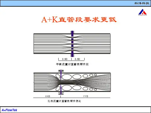
2.直管段要求低平衡流量传感器能将流场平衡,调整稳定,且压力恢复比传统节流装置快两倍,大大缩短了对直管段的要求。
大多数情况下直管段可以小至0.5D~2D,尤其对于特殊或昂贵的管道,采用平衡流量计可以省去大量的直管段。
3.永久压力损失低平衡流量计的对称平衡设计,减少了涡流的形成和紊流摩擦,降低了动能的损失,在同样的工况下,与传统节流装置比较,压力损失较少了70%,接近文丘里管,从而节省了相当大的运行成本,值得大量推广。
4.量程比宽与传统节流装置相比,平衡流量计极大提高了测量量程比.研究结果显示,雷诺数大于50000时,选择合适的孔径参数,平衡流量计无上限,根据工业测量实际应用的需要,常规测量量程比为10:1,选择合适的参数可以做道30:1或更高。
平衡流量计中文使用说明书平衡流量计中文使用说明书发布时间:2011-7-13 20:19:29平衡流量计中文使用说明书一、概述平衡流量计应用:众所周知,流体在管道中被输送时,往往要流经各种阀门、弯头、三通、异径管等阻流件,流体通过这些阻流件时,会产生各种扰动,影响正常的测量,使流量计带来一定的现场安装附加误差,特别是传统的差压式流量计等更是如此。
而新一代平衡流量传感器巧妙的将整流与测量合为一体,具有明显的稳定流场的作用,最大限度的降低附加误差,使得实际使用精度与理论精度相一致,是一种具有广阔应用前景的新一代差压式流量计,将在天然气、化工、石油、钢铁、发电、造纸、印染、制药等各行各业管道输送流体测量中展现她的身影。
平衡流量计(传感器)主要技术特点如下:1、测量精度高:由于平衡流量传感器实际上是一个流量整流器,能够有效的消除漩涡和改善速度分布畸变,使流场近似理想状态,故测量时,贸易计量精度可达0.3级,常规的测量可达0.5级。
2、量程比宽:由于大口径小流量测量是大多数流量传感器的难题,而平衡流量传感器是多孔结构,选择合适的等效直径比,可偏重于主要测量下限流量又兼顾上限流量,使得常规流量测量量程比为10:1,如果参数选择的合适可提高到30:1或者更高。
3、直管段要求低:一定长度的直管段主要是用来使流体在其中流动时趋于平稳,而平衡流量传感器本身就是一个流动调整器,因此它几乎可直接连接到阀门、三通、弯头等阻流件后,并不影响正常的测量。
4、永久压力损失低:管道中装上流量传感器,由于它的阻流作用不可避免的要产生压力损失,而平衡流量传感器中的多孔结构可分散阻力,有效的减小了涡流的形成和紊流摩擦,从而降低永久压力损失。
5、平衡流量计主要技术参数指标:1、口径:从DN10-----DN30002、精度等级:±0.3%、±0.5%、±1.0%3、重复性:0.1%4、量程比:10:1、30:1(或者更高)5、介质操作温度:<600℃6、介质操作压力:≤25MPa7、永久压力损失(Pa):≤0.31ρV2 ρ—介质密度Kg/m3 V—平均流速 m/s) (8、可测双向流二、平衡流量计工作原理:在充满流体的管道中固定放置一个流通面积小于管道截面积的阻流件(俗称节流装置),则管道内流体在通过该节流装置时就会局部收缩,在收缩处流通面积变小,流速增加,静压降低,因此,在节流装置前后将产生一定的差压,平衡流量传感器也是基于这一原理工作的,它不但能够产生差压,而且由于平衡流量传感器中的节流装置还是一个整流器,所以产生的差压特别的稳定,根据流体力学中的质量守恒定律和能量守恒定律可计算出流体的体积流量和质量流量,如下:q v=K(△P/ρ)1/2或 q m=K(△P·ρ)1/2—体积流量(m3/h);式中:qV—质量流量(kg/h);qm△P—输出差压(kpa);K—流量标定系数;ρ—流体密度(kg/m3)。
平衡流量计一、概述平衡流量计是按国标GB2624在标准孔板和流动调整器的基础上研发的一种新型节流式流量传感器。
平衡流量计用于安装在各种扰动的下游,以最短的直管段敷设提供卓越的性能。
二、测量原理平衡流量计是也一种差压式流量仪表,其工作原理与其他差压式流量计一样,都是基于密封管道中的能量转换原理:在理想流体的情况下管道中的流量与差压的平方根成正比;用测出差压值根据伯努利方程即可计算出管道中的流量。
平衡流量计流量传感器是一个多孔的圆盘节流整流器,安装在管道的截面上,当流体穿过圆盘的整流孔时,流体将被平衡整流,涡流被最小化,形成近似理想流体,通过取压装置,可获得稳定的差压信号,根据伯努利方程计算出体积流量、质量流量。
流量计算公式:式中:qm ,qv——分别为质量流量(㎏/s)和体积流量(m3/s);C——流出系数;ε——可膨胀性系数;d——节流件开孔直径,m;β——直径比,β=d/D;D——管道内径,m;ρ1——被测流体密度,㎏/m3;Δp——差压,Pa;三、特点1、测量精度高由于平衡流量计流量传感器具有多孔对称结构特点,能对流场进行平衡整流,降低了涡流、振动和信号噪声,流场稳定性大大提高,使线性度比传统节流装置提升了5~10倍。
2、直管段要求短平衡流量计流量传感器能将流场整流稳定、且压力恢复比传统节流装置快2倍,大大缩短了对直管段的要求。
一般情况下直管段要求为前2D、后2D,从而省去大量直管段,尤其是特殊昂贵的材料的管道。
3、量程比宽平衡流量计流量计正常情况下量程比为15:1,选择合适的参数可以做到30:1.平衡流量计流量计的β值范围为0.25~0.90。
4、永久压力损失低平衡流量计流量计多孔对称的平衡设计,减少了涡流的形成和紊流的摩擦,降低了动能的损失;在产生同样差压值情况下,永久压力损失约为传统节流装置的1/3,节省了相当大的运行成本,是一种节能型仪表。
5、耐脏污不易堵平衡流量计流量计多孔对称的设计,减少了涡流的形成和紊流的摩擦,降低流场死区,保证脏污介质顺利通过函数孔,因此平衡流量计流量计可用于测量各种脏污介质,如焦炉煤气、高炉煤气、渣油、回炼油、水煤浆等等。
目录1概述22 工作原理 23 主要特点 34 技术参数 45 主要结构及结构间距尺寸 56 安装77 调试及运行118 选型资料121概述FWE 多孔平衡流量计是由多孔平衡节流装置,差压变送器、显示仪表(也可以直接接计算机系统)组成。
FWE 多孔平衡节流量计是一种基于差压原理进行流量测量的流量仪表,流量传感器的结构是将孔板与整流器进行合理的组合,即在一块板上依据一定的计算和函数关系开若干个孔,通过测量板两侧的差压,进行流量测量。
多孔平衡式节流装置与差压变送器、显示仪表(或计算机)配套使用,可实现对流量的测量、显示、累积。
多孔平衡流量计由于其特殊的结构,特别适合现场直管段短、介质较脏、流量较低的流量测量。
同时由于其结构较简单、安装维护方便,因此可广泛应用于冶金、电力、化工、纺织、轻工、供热等工业的流量测量中。
2 工作原理FWE 多孔平衡节流装置由于是在孔板基础上发展而成的,与标准节流装置的工作原理是一样的,即基于伯努力方程和流体连续性方程。
当流体流经多孔平衡节流装置时,流体流速加快,从而静压降低,这样在多孔平衡节流装置前后产生一个静压差,通过对差压的测量,实现对流体流量的测量(见图一)),差压的平方根与流量成正比。
多孔孔板流量传感器是一个多孔的圆盘节流整流器,当流体穿过圆盘的整流孔时,流体将被平衡整流,流体被最小化,形成近似理想流体,故称平衡流量计,也称自整流流量计。
1质量流量与差压的关系由下式确定:体积流量与差压的关系由下式确定:式中:q m —流体的质量流量,Kg/sq v —流体的体积流量,m 3/sC —流出系数ε—可膨胀系数,对于液体 ε=1,对于气体、蒸汽 ε<1d —节流件开孔尺寸,mβ—直径比,β=d/DD —管道內径,mρ —被测流体密度,㎏/m 3 Δp —差压,Pa 。
3 主要特点由于F WE 多孔平衡流量计采用了类似整流器一样的几何结构,因此其即保留了孔板的一些优点,同时也吸收了整流器的很多优点,在实际应用中有如下特点和优势:3.1 测量精度高由于多孔平衡流量计具有多孔对称结构特点,能对流场进行平衡整流,降低了涡流、振动和信号离汛,流场稳定性大大提高,此结构还兼备了消声的特点,可以大幅度降低介质噪声,使传输的信号更加稳定。
SAMPLE 平衡流量计
一、公司简介:
美 国 善 元 琛 波 自 动 化 设 备 公 司 (Sunysample automation equipment company) 是专业从事差压流量控制仪表的研发生产公司,公司经过大量的数据积累和试验,仪表符合流体力学,优化行业控制,让流量测量技术得到了新的创新和突破。
南京善元琛波自动化设备有限公司坐落于江苏省南京市紫金(六合中山)科技创业园,距离南京市中心23 公里,距离南京长江二桥出口3 公里,是贯 通苏南、苏北的交通要道,是江、浙、沪地区辐射内陆的交通枢纽。
南京善元琛波自动化设备有限公司是美国善元琛波公司在中国授权的生产企业,并使用美国注册商标“S ample”,中文注册商标“琛波”。
公司成立以来一直注重产品品质和研发,通过了ISO9001质量管理体系认证,并取得专利证书,专利号为ZL 2015 2 0131896.7。
公司主要生产:平衡流量计、皮托巴流量计、楔形流量计等差压式流量计及其配套附件等。
公司建有标准压力试验、标准表法水流量检测装置等仪表性能检测设备,并和国家蒸汽流量站等国家级计量检测站及国内知名大学合作,保证了产品的品质。
公司产品主要用于石油、冶金、化工、电力、城市热网、供水、玻璃、汽车制造等行业。
公司秉承“以质量求生存,以服务求发展”的方针,提供高品质的产品服务。
二、性能特点
测量精度高
由于平衡流量传感器采取多孔对称分布结构,能整流流场,使流场平衡稳定,降低了涡流、振动和信号噪音,流场稳定性大大提高,表体采用独特的专有取压装置,使精度比传统节流装置提高5-10倍以上。
经过实流标定,传感器精度可达0.3、0.5%,适用于贸易计量场合;
几何尺寸检验,传感器精度可达0.5%、1.0%,适用于过程控制场合
平衡流量计加工重复性极高,在实流标定数据基础上,可实现几何尺寸法检定。
直管段要求低
因平衡流量计能整流流场,使流场平衡稳定,
且压力恢复比孔板快两倍,大大缩短了对直管段的要求,
一般情况下为0.5D-2D,如图。
采用平衡流量计可
以省去大量直管段,尤其是特殊昂贵材料的管道。
量程比宽
根据美国SUNY SAMPLE自动化设备公司研究、试验的
结果显示:雷诺数大于5*104时,选择合适的孔径比,平衡流量传感
器测量量程比足够大。
根据工业测量的实际需求,常规测量量程比为10:1,特殊场合测量量程比可优于20:1
耐脏污不易堵
平衡流量计因多孔平衡对称设计,减少了紊流剪切力和涡流的形成,从而大大降低了滞留死区的形成,保证脏污介质顺利通过多个孔,减少了流体孔被堵塞的可能。
双向流测量
平衡流量计的左右结构可完全对称设计,通过导压
管导压连接形式的处理,或采用一台能测正负压的差压变送
器,通过积算仪或DCS(或PLC)进行分段检测计算,
可以十分方便的测量双向流.
永久压力损失低
平衡流量计独特的平衡设计,减少了涡流的形成和紊流摩擦,降低了动能损失,在同样的测量工况不降低差
压值的情况下,可比传统节流装置降低到1/2-1/3的永久压力损失,从而节省了相当大的运行成本,是一种节能型仪表。
压力损失对比表
三、公司产品照片。