LGP平衡流量计(多孔孔板)说明书
- 格式:pdf
- 大小:339.83 KB
- 文档页数:11
LGPBALANCED METER ( MULT-HOLE ORIFICE FLOW METER)LGP平衡式流量测量节流装置使用说明书LGP-DT-JS-1020-2018(A)感谢您选择丹东通博电器(集团)有限公司的产品。
本使用说明书给您提供有关安装、连接和调试以及针对维护、故障排除和贮存方面的重要信息。
请在安装调试前仔细阅读并将它作为产品的组成部分保存在仪表的近旁,供随时翻阅。
并可通过下载本说明书。
如未遵照本说明书进行操作,则本仪表所提供的防护可能会被破坏。
商标、版权和限制说明通博、通博电器、通博泵业、DDTOP、均为公司的注册商标。
本仪表的性能规格自发布之日起生效,如有更改,恕不另行通知。
丹东通博电器(集团)有限公司有权在任何时候对本说明书所述的产品进行修改,恕不另行通知。
质保丹东通博电器(集团)有限公司保证所有产品自出厂之日起,一年之内无材料和制造工艺方面的缺陷。
在质保期内,如产品出现质量问题而返回,提出的索赔要求经制造厂检验后确定属于质保范围内,则丹东通博电器(集团)有限公司负责免费为买方(或业主)维修或更换。
丹东通博电器(集团)有限公司对因设备使用不当,劳动力索赔、直接或后续损伤以及安装和使用设备所引起的费用概不负责。
除了关于丹东通博电器(集团)有限公司某些产品的特殊书面保修证明,丹东通博电器(集团)有限公司不提供任何明示或暗示的质量保证。
质量丹东通博电器(集团)有限公司通过了ISO9001质量体系认证,产品生产的全过程均严格依照质量体系的规定范围执行,对产品和服务质量提供最强有力的保证。
1安全提示 (4)1.1爆炸可能会导致死亡或严重伤害。
(4)1.2过程泄漏可能导致严重伤害或死亡。
(4)1.3不遵守安全安装准则可能导致死亡或严重受伤。
(4)2产品说明 (4)2.1产品主要结构 (4)2.2工作原理 (5)2.3包装 (5)2.4吊装运输 (6)2.5仓储 (6)3主要执行标准 (6)3.1 产品特点 (6)3.2主要参数 (6)3.3应用范围 (7)4管道式外形尺寸示意图 (7)5开箱及检查 (8)5.1开箱验货注意事项 (8)5.2检查内容 (8)6安装 (8)6.1安装工具 (8)6.2安装技术要求 (8)7 故障分析与排除 (10)8 维护 (10)9 拆卸 (11)9.1警告 (11)9.2 废物清除 (11)10 产品认证 (11)1安全提示出于安全的原因,明确禁止擅自改装或改变产品,维修或替换只允许使用由制造商指定的配件。
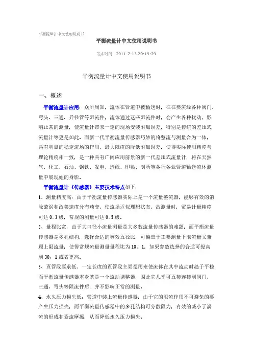
平衡流量计中文使用说明书平衡流量计中文使用说明书发布时间:2011-7-13 20:19:29平衡流量计中文使用说明书一、概述平衡流量计应用:众所周知,流体在管道中被输送时,往往要流经各种阀门、弯头、三通、异径管等阻流件,流体通过这些阻流件时,会产生各种扰动,影响正常的测量,使流量计带来一定的现场安装附加误差,特别是传统的差压式流量计等更是如此。
而新一代平衡流量传感器巧妙的将整流与测量合为一体,具有明显的稳定流场的作用,最大限度的降低附加误差,使得实际使用精度与理论精度相一致,是一种具有广阔应用前景的新一代差压式流量计,将在天然气、化工、石油、钢铁、发电、造纸、印染、制药等各行各业管道输送流体测量中展现她的身影。
平衡流量计(传感器)主要技术特点如下:1、测量精度高:由于平衡流量传感器实际上是一个流量整流器,能够有效的消除漩涡和改善速度分布畸变,使流场近似理想状态,故测量时,贸易计量精度可达0.3级,常规的测量可达0.5级。
2、量程比宽:由于大口径小流量测量是大多数流量传感器的难题,而平衡流量传感器是多孔结构,选择合适的等效直径比,可偏重于主要测量下限流量又兼顾上限流量,使得常规流量测量量程比为10:1,如果参数选择的合适可提高到30:1或者更高。
3、直管段要求低:一定长度的直管段主要是用来使流体在其中流动时趋于平稳,而平衡流量传感器本身就是一个流动调整器,因此它几乎可直接连接到阀门、三通、弯头等阻流件后,并不影响正常的测量。
4、永久压力损失低:管道中装上流量传感器,由于它的阻流作用不可避免的要产生压力损失,而平衡流量传感器中的多孔结构可分散阻力,有效的减小了涡流的形成和紊流摩擦,从而降低永久压力损失。
5、平衡流量计主要技术参数指标:1、口径:从DN10-----DN30002、精度等级:±0.3%、±0.5%、±1.0%3、重复性:0.1%4、量程比:10:1、30:1(或者更高)5、介质操作温度:<600℃6、介质操作压力:≤25MPa7、永久压力损失(Pa):≤0.31ρV2 ρ—介质密度Kg/m3 V—平均流速 m/s) (8、可测双向流二、平衡流量计工作原理:在充满流体的管道中固定放置一个流通面积小于管道截面积的阻流件(俗称节流装置),则管道内流体在通过该节流装置时就会局部收缩,在收缩处流通面积变小,流速增加,静压降低,因此,在节流装置前后将产生一定的差压,平衡流量传感器也是基于这一原理工作的,它不但能够产生差压,而且由于平衡流量传感器中的节流装置还是一个整流器,所以产生的差压特别的稳定,根据流体力学中的质量守恒定律和能量守恒定律可计算出流体的体积流量和质量流量,如下:q v=K(△P/ρ)1/2或 q m=K(△P·ρ)1/2式中:q V—体积流量(m3/h);q m—质量流量(kg/h);△P—输出差压(kpa);K—流量标定系数;ρ—流体密度(kg/m3)。

使用说明书LG系列动压测定装置标准孔板动压测定装置1 概述在流量仪表中,使用最广泛的为差压流量仪表,占流量仪表的70%左右。
差压流量仪表的检测元件为节流装置,它分孔板、标准喷嘴、文丘里管。
标准喷嘴又分长径喷嘴,ISA1932喷嘴。
这里叙述的为长颈喷嘴(以下简称喷嘴)。
1.1用途在电厂,随着发电机组的发展及容量的增大,机组技术参数也相应提高,对于主蒸汽的压力在10MPa以上,温度为555℃左右,一般应采用长颈喷嘴,从国外引进的机组上也都采用了长颈喷嘴来测量主蒸汽的流量。
长颈喷嘴与压差计或差压变送器(以上简称仪表)配套组成差压流量计,用于蒸汽的流量和调节,广泛地应用于电力等工业部门。
.1.2 特点由于喷嘴被铆、焊于测量管内,其承受工作压力高于其他节流装置;由于它自身结实,我们又考虑到测量管和喷嘴的线膨胀系数,故在特高温度下喷嘴能自由膨胀不致变形,从而确保特高温下使用,且保证了测量精确度;由于它的流量系数а高于其他节流装置,故可选择较小压差值,故压力损失小;与其它节流装置一样,他与流体接触部分无可动部件性能稳定可靠。
1.3 型号编制2 .技术指标a. 公称通经:D N=50~600mmb. 公称工作压力:P N≤60Mpa;c. 工作温度:t≤555℃;d. 直径比: β=0.20~0.80;e. 雷诺数范围 R=104~107。
3. 测量原理充满管道的流体流经管道中的喷嘴 时,流束将在它的喉部形成局部收缩,从而 使流束增加,静压力降低,于是在喷嘴前后 产生了静压力差(差压)。
流体的流速愈大, 其压差也愈大,所以它是通过测量压差来 测量流经管道的流量大小。
这种测量方法是以能量守恒定律和流 动连续方程为基础的,假设未经标定的节流已通过充分标定的节流装置几何相似和 图1 长颈喷嘴测量原理 动力相似,亦即符合标准的要求,则质量或 体积的流量与差压的关系,可由下列公式 确定。
长颈喷嘴的基本方式:实用质量流量方程:q m =1120e R P d V C ρ⋅∆⋅⋅α⋅ε⋅⋅ 实用体积流量方程:q v =1120e R P d V C ρ⋅∆⋅⋅α⋅ε⋅⋅ 式中: q m ——流体质量流量(t/h 、kg/h );q v ——流体体积流量(m 3/h 、m n /h ); C ——常数;V Re ——管道粗糙度修正系数; ε——流速膨胀系数; α0——光管流量系数;d 1——工作温度下长颈喷嘴开孔直径(mm ); ΔP ——差压上限(KPa );ρ1——工作状态下流体密度(kg/m 3)。
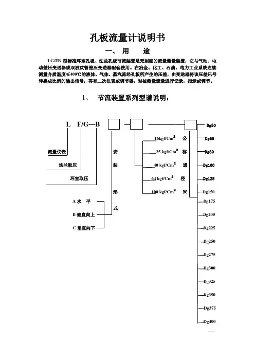
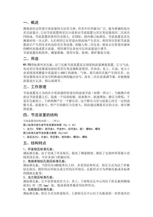
孔板流量计说明书一、用途LG/FB型标准环室孔板、法兰孔板节流装置是无刻度的流量测量装置,它与气动、电动差压变送器或双波纹管差压变送器配套使用。
在冶金、化工、石油、电力工业系统连续测量介质温度≤400℃的液体、气体、蒸汽流经孔板所产生的压差,由变送器将该压差讯号转换成比例的输出信号,再有二次仪表或调节器,对被测量流量进行记录,指示或调节。
1、节流装置系列型谱说明:Dg5016kgf/Cm²25 kgf/Cm²40 kgf/Cm²64 kgf/Cm²100 kgf/Cm²g175g200g225g250g275g300g325g350※注:公称通径根据工艺条件要求,通径从Φ50~Φ418MM。
例:LGBA—16—80表示:标净环室孔板节流装置,水平安装,工作压力6kgf/Cm²公称通径为Dg80二作用原理和结构1、基本原理在管道内部装上孔板或喷咀等节流件,由于节流件的孔径小于管道内径,当流体流经节流件时,流束截面突然收缩,流速加快。
节流件后端流体的静压力降低,于是在节流件前后产生产生静压力差(见图1),该静压力差与流体过的流体流量之间有确定的数值关系、符合Q=K。
△P 。
用差压变送器(或差压计)测量节流件前后的差压,实现对流量的测量。
2、节流装置的结构节流装置的结构如图2、3所示:图2、标准环室孔板节流装置结构示图(Pg≤25)1、法兰2、导管3、前环室4、节流件5、后环室6、垫7、螺栓8、螺母图3、标准法兰孔板节流装置示意图(Pg≥64)1、取压法兰2、孔板3、导压管4、密封垫5螺母6螺栓三、安装要求节流装置的安装和适用于下列管段和管件有关:节流件上游侧第一阻力件、第二阻力件,节流件下右侧第一阻力件,从节流件上游第二阻力件到下游第一阻力件之间的管段以及差压讯号管路等。
1、管道条件:(1)节流件前后的直管段必须是直的,不得有肉眼可见的弯曲。
MS65G06030003Positive Displacement Flowmeters GM015 series instruction manualGM015 Pulse Meter From serial No. CXXXXThank you for purchasing a G PI G M Series Flow Meter. Please take a few minutes to read thorugh this manual before installing and operating your meter. If you have any problems with the meter, refer to the maintenance and trouble shooting sections of this manual.This manual contains connection and operating instructions for the G M015Series meters with pulse outputs. For models with display, an additonal instruction manual is supplied. If you need further assistance, contact yourlocal GPI representative or contact GPI by telephone or fax for advice.The G PI G M Series Flow Meter has incorporated the oval rotor principal into its design. This has proven to be a reliable and highly accurate method of measuring flow. Exceptional repeatability and high accuracy over a wide range of fluid viscosities and flow rates are features of the GM Series flow meter design. The low pressure drop and high pressure rating means the GM Series flow meter is suitable forboth gravity and pump (in line) applications.The G PI G M Series flow meters are available in either aluminium, Bronze or 316 stainless steel. Standard rotors are made from PPS (Polyphenylene Sulfide Resins) with optional 316stainless steel rotors available for both stainless steel and aluminium models.The G M015 Series is available with either;* Standard Pulse* Standard LC Display and PulsePLEASE READ THIS INFORMATIONCAREFULLY BEFORE USE!Before use, confirm the fluid to be used is compatible with the meter (refer to the G PI fluid compatibility chart), or consult your local G PI representative for advice.To prevent damage from dirt or foreign matter, GPI recommends a Y or Basket type 60 mesh strainer be installed as close as possible to the inlet side of the meter (if required contact Macnaught for further information).Note: When a strainer is installed it should be regularly inspected andcleaned. Failure to keep the strainer clean will dramatically effect flow meter performance.To prevent damage to the meter slowly fill the system with fluid (this will prevent damage caused by air purge).Note: Failure to do this could damage the meter.For pump applications, turn off the pump at the end of each day.Maintenance can be carried out to the liquid crystal displays and pulse units without removing or isolating the meter from the line. When maintenance to any other part of the meter is required, the meter must be isolated and the line pressure reduced.The reed switch pulse unit can cause inaccurate rate counts when used with high speed counters. It is advised that a debounce circuit be used or alternatively use the hall effect sensor option.either Reed switches or Hall Effect1 Bypass LineFlow OutletFlow InletStrainer Do Not Install Meter This WayDisassemblyEnsure that the fluid supply to the meter is disconnected, and the line pressure is released before disassembly, with the exception for repair or maintenance to the LC Display or PCB where there is nonecessity to isolate the meter from flow.Refer to the exploded parts diagram on page 5.1a]Units with Pulse Caps; Undo theconduit connector, remove pulse cap (item 9) and remove the wires from the pulse terminal board (item 5).1b]Standard LC Display; Mark thedisplay orientation with a marking pen, unscrew the four large screws on top of the LC Display. Carefullyseperate the LC Display from theReed Switch Connections for PCB Terminals - refer Fig.3Hall Effect Sensor Connections - refer Fig.4Service Instructions3Contact rating 15VA Maximum Voltage 150VDC Configuration 12 x pulse outputsConfiguration 2Link 2 & 3 for doublepulse output1 x Reed Switch1 - Reed Switch2 - Reed Switch3 - HE Common -4 - HE Signal5 - HE Supply +Hall Effect Voltage 4.5 to 24 VDC Current Draw Minimum 4.6mA Output NPN Open Collector 25mAplastic housing and disconnect the wires from the pulse terminal block.2]Remove the mounting adaptor plate and gasket.3]Loosen the eight cap head screws (Item 7) that hold down the meter cap (Item 4), remove the screws,washers and lift off the cap.4]Remove the o’ring (Item 2) from the o’ring groove in the meter cap (Item 4).5]Remove rotors (Item 3).Reassembly1]Before reassembling check the condition of the rotors (replace if necessary).2]Check that the smooth side of the rotors (not the plug side) is facing you when inserting the rotors, the smooth side of the rotor is the magnet side. There is no difference between rotor one or rotor two.3]Replace the rotors (Item 3) onto the shafts at 90o to each other (refer Fig.5) and check their operation byturning either of the rotors. If the rotors are not in mesh correctly or do not move freely, remove one of the rotors and replace correctly at 90o to the other rotor. Re-check the operation of the rotors.4]Replace the o’ring (Item 2) into groove in the meter cap, if the o’ring has grown or is damaged in any way replace it with a new part.5]Replace the meter cap making sure that the locating pin in the body lines up with the hole in the meter cap. Insert the cap head screws (Item 7) and tighten in the sequence 1, 6,2, 5, 3, 7, 4, 8.6]The replacement of cables and connectors are a reversal of the disassembly procedure, replace conduit fitting if required. When replaceing the Standard LC Display,confirm the orientation marks made on disassembly are aligned then screw the register into place.7]T est the meter by turning the rotorswith a finger or by applying very low air pressure (no more than a good breath) to one end of the meter,before returning the meter to the line.Pulse Circuit Board (PCB) Notes:The pulse PCB (Item 5) is fitted with (A)two reed switches; (B) hall effect sensors; or (C) one reed switch and one hall effect sensor. The PCB board is fastened to the meter cap (Item 4) by two screws and stand off’s. All care and caution should be taken when removing or handling the PCB as both the reed switch and hall effect sensor are fragile.Individual reed switches or hall effectsensors are not available as individual replacement parts and are only available with the PCB (Item 5).5Rotors must be at 90o to each other.Rotor #2Rotor #111MS191B Meter Body 1 1/2” BSP (Aluminium)11MS191N Meter Body 1 1/2” NPT (Aluminium)11MS189B Meter Body 1 1/2” BSP (Stainless Steel)11MS189N Meter Body 1 1/2” NPT (Stainless Steel)11MS191F Meter Body 1 1/2” ANSI 150lb Flange (Aluminium)11MS191D Meter Body 1 1/2” DIN16 Flange (Aluminium)11MS189F Meter Body 1 1/2” ANSI 150lb Flange (S/Steel)11MS189D Meter Body 1 1/2” DIN16 Flange (S/Steel)21u BS243TE “O” Ring (Teflon)21u BS243V “O” Ring (Viton)32u MS58S Rotors PPS (Polyphenylene Sulfide Resins)32u MS58-1S Rotors (Stainless Steel)32u MS58HS High Viscosity Rotors (PPS)32uMS58-1HS High Viscosity Rotors (Stainless Steel)41MS220Meter Cap (Aluminium)41MS221Meter Cap (Stainless Steel)51u MS201-R PCB (Standard Reed Switch)51uMS201-HE PCB (Hall Effect Sensor)51MS201-R/HE PCB ( 1 Reed Switch & 1 Hall Effect Sensor)64MS284S PCB Board Screws76u MS116S Meter Cap Screws (Standard)76u MS180S Meter Cap Screws (Stainless Steel)81uMS300Pulser Cap Gasket91MS160Pulser Cap (Aluminium) 20mm Conduit Thread 91MS160N Pulser Cap (Aluminum) 1/2” NPT Thread91MS170Pulser Cap (Stainless Steel) 20mm Conduit Thread 91MS170N Pulser Cap (Stainless Steel) 1/2” NPT Thread 104MS115S Pulser Cap Screw (Stainless Steel)111MS37Warning Lebel (Not Shown)131Customer to SpecifyLegend Plate (Not Shown) inc. Hammer ScrewsItem No.No.Off.Part or Set(Order from this column only)Part DescriptionKey:Indicates recommended Spare Parts to stock Bold text indicates Stainless Steel Model PartsRec.PartsMeter TypeFlow Ranges(Litres per minute/US Gallons per minute)Above 5 Centipoise Below 5 Centipoise Accuracy of Reading Maximum Viscosity*Maximum Operating Pressure**Operating Temp. RangeAlum.S.S.Pulse TypePulses Per Litre/US Gallon Pulse10 to 250/ 2.6 to 6615 to 235/ 4 to 62+/- 0.5%1000 Centipoise1800 kPa/ 260 PSI/ 18 BAR-10°C/ 14°F to 80°C/ 176°F -10°C/ 14°F1 to 120°C/ 248°FDual Reed Switches or HallEffect Sensor or combination HE Sensor/Reed Switch14.5/ 29 or 54.9/ 109.7* Unless High Viscosity Rotors are fitted ** Meter conforms to PED 97/23/EC CAT 1.Great Plains Industries, Inc. Limited Warranty PolicyGreat Plains Industries, Inc., 5252 East 36th Street North, Wichita, Kansas USA67220-3202, hereby provides a limited one year warranty against defects in material and workmanship on all products manufactured by Great Plains Industries, Inc. This warranty shall extend to the purchaser of this product and to any person to whom such product is transferred during the warranty period.The warranty period shall begin on the date of the original new equipment purchase. Warrantor’s obligation hereunder shall be limited to repairing defective workmanship or replacing or repairing any defective part or parts. This warranty shall not apply if:a.)the product has been altered or modified outside the warrantor’s duly appointedrepresentative;b.)the product has been subjected to neglect, misuse, abuse or damage or has been installed or operated other than in accordance with the manufacturer’s operating instructions.To make a claim against this warranty, notice of claim must be given in writing to the company at its above address no later than 30 days after the expiration of the warranty period. Such notice shall identify the defect in the product. The company shall, within 14 days of receipt of such notice, notify the customer to either send the product, transportation prepaid, to the company at its office in Wichita, Kansas, or to duly authorized service center. The company shall perform all obligations imposed on it by the terms of this warranty within 60 days of receipt of the defective product.GREAT PLAINS INDUSTRIES, INC. EXCLUDES LIABILITY UNDER THIS WARRANTY FOR DIRECT, INDIRECT, INCIDENTAL AND CONSEQUENTIAL DAMAGES INCURRED IN THE USE OR LOSS OF USE IF THE PRODUCT WARRANTED HEREUNDER.The company herewith expressly disclaims any warranty of merchantability or fitness for any particular purpose other than for which it was designed.This warranty gives you specific rights and you may also have other rights which vary from U.S. state to U.S. state.NOTE: In compliance with MAGNUSON MOSS CONSUMER WARRANTY ACT- Part 702 (governs the resale availability of the warranty terms).AUTHORIZED DISTRIBUTOR:。

孔板流量计说明书孔板流量计1产品功能用途和适用范围测量流经管道介质流量的方法有多种,但其中应用最广泛、最普遍的是节流装置,它的使用历史悠久,在国际、国内都已经标准化,在石油、化工、冶金、电力、轻纺、科研等行业的生产过程中,大量地使用着各种类型的节流装置进行流体流量的测量,控制和调节,节流装置具有结构简单、牢固、工作可靠、性能稳定、精确度高、价格低廉等优点,因而节流装置的用量与其它流量仪表相比占有绝对优势。
节流装置与差压流量变送器配套使用,现场量程连续可调,并能输出标准信号(0~10mAD、C或4~20mAD、C)再输入到二次仪表,便显示出管道内流体的瞬时流量和累积总量,若把标准信号输入到工业控制机,可以自动整点打印出瞬时流量和累积总量,为用户的使用提供了很大方便。
节流装置包括标准节流装置(包括标准孔板、标准喷嘴、标准文丘里管),和非标准节流装置(包括四分之一圆喷嘴、四分之一圆孔板、小孔板、双重孔板、圆缺孔板、锥形入口孔板等),取压方式有环室取压、法兰取压、当流体的雷诺数较低者或含有杂质时,可选用非标准节流装置。
2产品型式号及编码2.1产品型号及编码节流装置的型号及含义如下LGB —XX X X XX X XA码B码C码D码E码F码F:法兰取压J:环室取压孔板节流装置A~F码的含义如下:A码—表示管道公称通径用二位数表示;B码—表示公称工作压力,用一位数表示;C码—表示公称通径管子外径尺寸系列(GB1245-90),用一位数表示;D码—表示孔板类别,用二位数表示;E码—表示孔板材质与法兰材质,用一位数表示;F码—表示孔板附件,用一位数表示。
上述各码具体代码详见《节流装置编码一览表》。
2.2 产品组成a 法兰取压的节流装置:由取压法兰、节流件、密封垫片及紧固件,配二次仪表可显示瞬时流量及累积总量。
b环室取压的节流装置:由法兰、环室、节流件、密封垫片及紧固件,配二次仪表可显示瞬时流量及累积总量。
3产品工作原理与主要结构3.1 原理节流装置是人为地在介质流通的管道内造成节流(如图1)当被测介质流过节流装置后,造成一个局部收缩,流束集中,流速增加,静压力降低,于是在节流件的上下游两侧产生一个静压力差。
平衡流量计安装使用说明书淮安森菱仪表有限公司2010.10.5概述平衡流量计使用流体力学研究成果对传统节流装置进行较大的改进,具有平衡流量计整流的显著特征。
传统节流装置只有一个流通孔径,节流后使流体失去了理想状态;而平衡流量计有多个函数孔径,能最大限度的把流场平衡流量计整流成理想流体,从而将差压式流量计的优势发挥的淋漓尽致。
平衡流量计几乎适用于所有流体测量,是流体测量技术的一场革命,目前平衡流量计已经广泛应用到石油、化工、冶金、电力、天然气、水处理等行业。
产品特点1.线性度高、重复性好。
平衡流量计流量传感器具有对称多孔结构特点,能对流场进行平衡流量计,降低了涡流,振动和信号噪声,流场稳定性大大提高,使线性度比孔板提升了5~10倍,重复性提高了54%,为0.15%,从其综合性能来看,平衡流量计属于高档流量计行列。
5:1量程比时,线性度可达±0.3%;7:1量程比时,线性度可达±0.5%;10:1量程比时,线性度可达±1.0%;2.直管段要求低。
平衡流量计流量传感器由于流场稳定,且压力恢复比孔板快两倍,大大缩短了对直管段的要求其前后直管段一般为前3D后1D,最小可以小于0.5D,从而省去大量直管段,尤其是特殊昂贵的材料的管道。
3.减少永久压力损失。
多孔对称的平衡流量计设计,减少了紊流剪切力和涡流的形成,降低了动能的损失,在同样的测量工况下,与孔板相比减少了2.5倍的永久压力损失,从而节省了相当大的运行能量成本,是一种节能 仪表,值得大量推广。
4.耐脏污不易堵。
多孔对称的平衡流量计设计,减少了紊流剪切力和涡流的形成,从而大大降低了滞留死区的形成,保证脏污介质顺利通过多个孔,减少了流体孔被堵塞的机会。
5.可直接替代孔板。
其与孔板具有相同的使用方法和外形,因此可以直接进行替换,不需要任何配管的变化和相关仪表的更改,很适合全厂能源计量EMS改造中将孔板改为平衡流量计。
6.流量测量范围宽。
平衡流量计一、概述平衡流量计是按国标GB2624在标准孔板和流动调整器的基础上研发的一种新型节流式流量传感器。
平衡流量计用于安装在各种扰动的下游,以最短的直管段敷设提供卓越的性能。
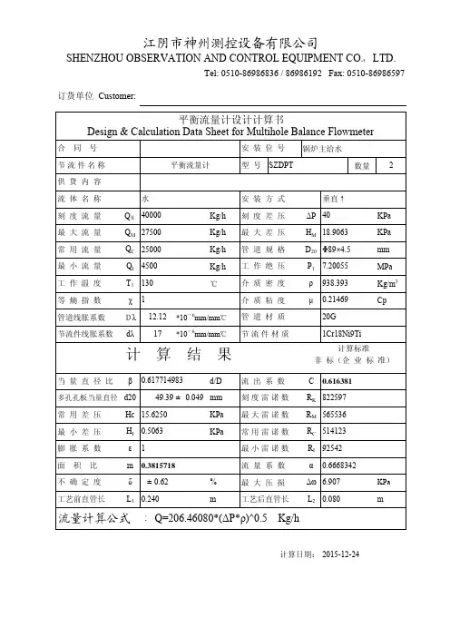
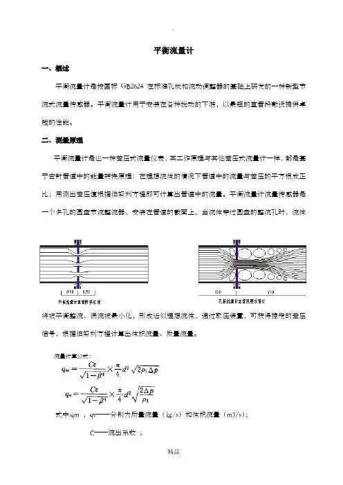
二、测量原理平衡流量计是也一种差压式流量仪表,其工作原理与其他差压式流量计一样,都是基于密封管道中的能量转换原理:在理想流体的情况下管道中的流量与差压的平方根成正比;用测出差压值根据伯努利方程即可计算出管道中的流量。
平衡流量计流量传感器是一个多孔的圆盘节流整流器,安装在管道的截面上,当流体穿过圆盘的整流孔时,流体将被平衡整流,涡流被最小化,形成近似理想流体,通过取压装置,可获得稳定的差压信号,根据伯努利方程计算出体积流量、质量流量。
流量计算公式:式中:qm ,qv——分别为质量流量(㎏/s)和体积流量(m3/s);C——流出系数;ε——可膨胀性系数;d——节流件开孔直径,m;β——直径比,β=d/D;D——管道内径,m;ρ1——被测流体密度,㎏/m3;Δp——差压,Pa;三、特点1、测量精度高由于平衡流量计流量传感器具有多孔对称结构特点,能对流场进行平衡整流,降低了涡流、振动和信号噪声,流场稳定性大大提高,使线性度比传统节流装置提升了5~10倍。
2、直管段要求短平衡流量计流量传感器能将流场整流稳定、且压力恢复比传统节流装置快2倍,大大缩短了对直管段的要求。
一般情况下直管段要求为前2D、后2D,从而省去大量直管段,尤其是特殊昂贵的材料的管道。
3、量程比宽平衡流量计流量计正常情况下量程比为15:1,选择合适的参数可以做到30:1.平衡流量计流量计的β值范围为0.25~0.90。
4、永久压力损失低平衡流量计流量计多孔对称的平衡设计,减少了涡流的形成和紊流的摩擦,降低了动能的损失;在产生同样差压值情况下,永久压力损失约为传统节流装置的1/3,节省了相当大的运行成本,是一种节能型仪表。
5、耐脏污不易堵平衡流量计流量计多孔对称的设计,减少了涡流的形成和紊流的摩擦,降低流场死区,保证脏污介质顺利通过函数孔,因此平衡流量计流量计可用于测量各种脏污介质,如焦炉煤气、高炉煤气、渣油、回炼油、水煤浆等等。
电磁流量计一、概况智能电磁流量计是我公司采用国内外最先进技术研制开发的全智能型电磁流量计,其全中文电磁转换器内核采用高速中央处理器。
计算速度非常快、精度高、测量性能可靠。
转换器电路设计采用国际先进技术,输入阻抗高达1015欧姆,共模抑制比优于100db,对于外来干扰以及60Hz/50Hz干扰抑制能力优于 90db,可以测量更低的电导率的流体介质流量。
其传感器采用非均匀磁场技术及特殊的磁路结构,磁场稳定可靠,而且大大的缩小了体积,减轻了重复,使流量计具有小型轻量化的特点。
二、特点◇管道内无可动部件,无阻流部件,测量中几乎没有附加压力损失,对直管段要求较低。
◇测量结果与流速分布、流体压力、温度、密度、粘度等物理参数无关。
◇在现场可根据用户实际需要在线修改量程。
◇高清晰度背光LCD液晶显示,可使直射阳光下或暗室内的读数变得容易。
全中文菜单操作,使用方便,操作简单,易学易懂。
◇采用SMD器件和表面贴装(SMT)电路可靠性高。
◇采用16位嵌入式微处理器,运算速度快,精度高,可编程频率低频矩形波励磁,提高了流量测量的稳定性,功耗低。
◇全数字量的处理,抗干扰能力强,测量可靠,精度高,流量测量范围可达150:1◇超低EMI开关电源,使用电源电压变化范围大,抗EMI好。
◇内部具有三个积算器可分别显示正向累计量、反向累计量及差值积算量,内部设有不掉电时钟,可记录16次掉电时间(10年)◇具有RS485、RS232、Hart和Modbus等数字通讯信号输出。
(选配)◇转换器具有自诊断报警输出、空负载检测报警输出、流量上下限报警输出、批处理控制等功能。
◇高压电磁流量计传感器采用PFA加网衬里技术,耐高压,抗负压,专门应用石油、化工等行业。
◇传感器采用先进加工工艺,使仪表具有良好的抗负压能力。
◇小时总量纪录功能,以小时为单位记录流量总量,适用于分时计量制。
(选配)三、工作原理电磁流量计测量原理是基于法拉第电磁感应定律。
流量计的测量管是一内衬绝缘材料的非导磁合金短管。
孔板使用说明书概述孔板使用流体力学研究成果对传统节流装置进行较大的改进,具有孔板整流的显著特征。
传统节流装置只有一个流通孔径,节流后使流体失去了理想状态;而孔板有多个函数孔径,能最大限度的把流场孔板整流成理想流体,从而将差压式的优势发挥的淋漓尽致。
孔板几乎适用于所有流体测量,是流体测量技术的一场革命,目前孔板已经广泛应用到石油、化工、冶金、电力、天然气、水处理等行业。
产品特点1.线性度高、重复性好。
孔板流量传感器具有对称结构特点,能对流场进行孔板,降低了涡流,振动和信号噪声,流场稳定性大大提高,使线性度比孔板提升了5~10倍,重复性提高了54%,为0.15%,从其综合性能来看,孔板属于高档行列。
5:1量程比时,线性度可达±0.3%;7:1量程比时,线性度可达±0.5%;10:1量程比时,线性度可达±1.0%;2.直管段要求低。
孔板流量传感器由于流场稳定,且压力恢复比孔板快两倍,大大缩短了对直管段的要求其前后直管段一般为前3D后1D,最小可以小于0.5D,从而省去大量直管段,尤其是特殊昂贵的材料的管道。
3.减少永久压力损失。
对称的孔板设计,减少了紊流剪切力和涡流的形成,降低了动能的损失,在同样的测量工况下,与孔板相比减少了2.5倍的永久压力损失,从而节省了相当大的运行能量成本,是一种节能仪表,值得大量推广。
4.耐脏污不易堵。
对称的孔板设计,减少了紊流剪切力和涡流的形成,从而大大降低了滞留死区的形成,保证脏污介质顺利通过多个孔,减少了流体孔被堵塞的机会。
5.可直接替代孔板。
其与孔板具有相同的使用方法和外形,因此可以直接进行替换,不需要任何配管的变化和相关仪表的更改,很适合全厂能源计量EMS改造中将孔板改为孔板。
6.流量测量范围宽。
根据试验结果,孔板的性能,使其流速可以从最小到音速;其最小雷诺数可低于200,最大雷诺数大于107;β值可选0.25~0.90。
7.长期稳定性好。
平衡流量计一、概述平衡流量计是按国标GB2624在标准孔板和流动调整器的基础上研发的一种新型节流式流量传感器。
平衡流量计用于安装在各种扰动的下游,以最短的直管段敷设提供卓越的性能。
二、测量原理平衡流量计是也一种差压式流量仪表,其工作原理与其他差压式流量计一样,都是基于密封管道中的能量转换原理:在理想流体的情况下管道中的流量与差压的平方根成正比;用测出差压值根据伯努利方程即可计算出管道中的流量。
平衡流量计流量传感器是一个多孔的圆盘节流整流器,安装在管道的截面上,当流体穿过圆盘的整流孔时,流体将被平衡整流,涡流被最小化,形成近似理想流体,通过取压装置,可获得稳定的差压信号,根据伯努利方程计算出体积流量、质量流量。
流量计算公式:式中:qm ,qv-—分别为质量流量(㎏/s)和体积流量(m3/s);C——流出系数;ε—-可膨胀性系数;d--节流件开孔直径,m;β--直径比,β=d/D;D-—管道内径,m;ρ1——被测流体密度,㎏/m3;Δp——差压,Pa;三、特点1、测量精度高由于平衡流量计流量传感器具有多孔对称结构特点,能对流场进行平衡整流,降低了涡流、振动和信号噪声,流场稳定性大大提高,使线性度比传统节流装置提升了5~10倍。
2、直管段要求短平衡流量计流量传感器能将流场整流稳定、且压力恢复比传统节流装置快2倍,大大缩短了对直管段的要求。
一般情况下直管段要求为前2D、后2D,从而省去大量直管段,尤其是特殊昂贵的材料的管道。
3、量程比宽平衡流量计流量计正常情况下量程比为15:1,选择合适的参数可以做到30:1.平衡流量计流量计的β值范围为0。
25~0。
90.4、永久压力损失低平衡流量计流量计多孔对称的平衡设计,减少了涡流的形成和紊流的摩擦,降低了动能的损失;在产生同样差压值情况下,永久压力损失约为传统节流装置的1/3,节省了相当大的运行成本,是一种节能型仪表.5、耐脏污不易堵平衡流量计流量计多孔对称的设计,减少了涡流的形成和紊流的摩擦,降低流场死区,保证脏污介质顺利通过函数孔,因此平衡流量计流量计可用于测量各种脏污介质,如焦炉煤气、高炉煤气、渣油、回炼油、水煤浆等等。
MS489G07030004Positive Displacement Flowmeters GM505 series instruction manualGM505 Mechanical meter • From serial No. CXXXXThank you for purchasing a GPI GM Series Flow Meter. Please take a few minutes to read thorugh this manual before installing and operating your meter. If you have any problems with the meter, refer to the maintenance and trouble shooting sections of this manual.This manual contains connection and operating instructions for the GM505Series meters with mechanical displays. If you need further assistance,contact your local GPI representativeor contact GPI by telephone or fax for advice.The GPI GM Series Flow Meter has incorporated the oval rotor principal into its design. This has proven to be a reliable and highly accurate method of measuring flow. Exceptional repeatability and high accuracy over a wide range of fluid viscosities and flow rates are features of the GM Series flow meter design. The low pressure drop and high pressure rating means the GM Series flow meter is suitable forbothgravity and pump (in line) applications.The GPI GM Series flow meters are available in either aluminium or 316stainless steel. Standard rotors are made from PPS.The GM505 Series mechanical displays have a resettable batch totaliser and non-resettable accumulative totaliser.PLEASE READ THIS INFORMATIONCAREFULLY BEFORE USE!Before use, confirm the fluid to be used is compatible with the meter (refer to the GPI fluid compatibility chart), or consult your local GPI representative for advice.To prevent damage from dirt or foreign matter, GPI recommends a Y or Basket type 60 mesh strainer be installed as close as possible to the inlet side of the meter (if required contact GPI for further information).Note: When a strainer is installed it should be regularly inspected and cleaned. Failure to keep the strainer clean will dramatically effect flowmeter performance.To prevent damage to the meter slowly fill the system with fluid (this willprevent damage caused by air purge).Note: Failure to do this could damage the meter.For pump applications, turn off thepump at the end of each day.registers gear train which provides an1 Bypass LineFlow OutletFlow InletStrainer Do Not Install Meter This WayDisassemblyEnsure that the fluid supply to the meter is disconnected, and the line pressure is released before disassembly. Refer to the exploded parts diagram on page 5for item numbers.1]Remove the four screws (Item 17)located on the face of the register.Then remove the face plate cover including register assembly.2]Remove the four register mountingscrews (Item 15). Then remove the lower half of the register housing.3]Remove the six cover plate screws(Item 12) and remove the cover plate (Item 11).4]Remove the four meter cap screws (Item5) and remove the meter cap (Item 4).5]Remove rotors (Item 3).Reassembly1]Clean all components beforereassembly.2]Before reassembly check thecondition of the rotors (Item 3).Replace if necessary.3]Replace the rotor (with the gear) onthe short shaft in the housing then place the 2nd rotor onto the shaft so as the rotors are at 90°to each other. (Refer Fig 3). Check rotor operation by turning either of the rotors. If the rotors are not in mesh correctly or do not move freely remove one of the rotors andreplace it correctly at 90°to the other rotor. Recheck the operation of the rotors.4]Inspect the gears (Item 6) in themeter cap (Item 4) for wear.(Replace if required, refer to spare parts on page 5 & 6).5]Replace the o-ring (Item 2) into thegroove in the meter cap, if the o-ring has been distorted or is damaged in any way replace it with a new part.6]Replace the meter cap, making surethe meter cap and the gear on the rotor meshes correctly with the gear in the meter cap (Item 4). Insert the allen screws (Item 5) and tighten in the sequence 1, 4, 2, & 3.7]Inspect the bevel gear (Item 13), o-ring (Item 10), and output gear (Item 7) for wear or damage. (Replace faulty components if necessary).8]Replacement of output shaft, bushand seal.Disassembly of output shafta.Remove the bevel gear.b.Remove the circlip and push out the output shaft assembly, including washer.c.Remove the seal.d.Carefully press out the output shaft bush (If required).Assembly of output shafta.Carefully press the new output shaft bush into place (Use L octite Primer 7471, as per instructions,followed by sealant Loctite 262).b.Insert a new seal into the groove of the output shaft bush.c.Replace the output gear and washer and replace the circlip to lock the output gear shaft into place.d.Replace the bevel gear (Item 13)and tighten the grub screw onto flat face of shaft.9]Place the o-ring (Item 10) into thegroove in the meter cap (Replace the o-ring seal if required).10]Place the cover plate onto the meter.Replace the cover plate screws and tighten the six cap head screws (Item 12) firmly.11]Place the lower cover plate of theregister into position. Replace the four screws (Item 15) and tighten.12]Position the register correctly on topof the lower register cover. Replace the four screws (Item 17) and tighten.13]T est the meter by turning the rotorswith a finger or by applying low air pressure (No more than a good breath) to one end of the meter,before returning meter to the line.5Rotors must be at 90o to each other.Rotor #2TROUBLE SHOOTING GUIDETROUBLEFluid will not flow through meterReduced flow through the meterMeter reading inaccurateFluid flows but no reading on meterFluid leaks into registerCAUSE a]Foreign matter blocking rotors b]Line strainer blocked c]Damaged rotorsd]Meter connections over tightened e]Fluid is too viscousa]Strainer is partially blocked b]Fluid is too viscousa]Fluid flow rate is too high or too low b]Fluid is too viscousc]Excess wear caused by incorrect installationa]Bevel gear is loose on shaft b]Rotor drive gear is damaged c]Transmission gears damaged d]Register gears damageda] Seal worn or damaged on the cover plateREMEDYa]Dismantle meter, clean rotors (Strainer must be fitted in line)b]Clean strainerc]Replace rotors (Strainer must be fitted in line)d]Re-adjust connectionse]See specifications for maximum viscosity a]Clean strainerb]See specifications for maximum viscositya]See “specifications” for minimumand maximum flow rates b]Bleed air from system c]Check meter body and rotors.Replace as required. Refer to installation instructions a]Tighten grub screws b]Replace rotor c]Replace gearsd ]Replace register assemblya]Replace seal (Check sealcompatibility with fluid)Item No.No.Off.Part or Set(Order from this column only)Part DescriptionRec.Parts 123457111310Key:* Parts for US Gallon Models Onlyu Indicates recommended Spare Parts to stock Bold text indicates Stainless Steel Model Parts8 / 98A / 9A O-ring Only12141516176202111MS298B Meter Body 1/2” BSP (Aluminium)11MS298N Meter Body 1/2” NPT (Aluminium)11MS337B Meter Body 1/2” BSP (Stainless Steel)11MS337N Meter Body 1/2” NPT (Stainless Steel)21u BS145TES “O” Ring (Teflon)21u BS145VS “O” Ring (Viton)32u MS342MS Rotors PPS (Polyphenylene Sulfide Resins)32uMS342MHS High Viscosity Rotors (PPS)41MS544S Meter Cap Liters (Aluminium)41MS547S Meter Cap US Gallons (Aluminium)41MS545S Meter Cap Liters (Stainless Steel)41MS546S Meter Cap US Gallons (Stainless Steel)54u MS346S Meter Cap Screws (Standard)54u MS350S Meter Cap Screws (Stainless Steel)61u MS539S Complete Gear Set - Liters61u MS541S Complete Gear Set - US Gallons 71u MS77S Output Gear & Shaft Assembly 81u MS78S Coverplate Seal/Bush Set Standard 8A 1u OR42CS Solvent o-ring (Perfluoro Elastomer)91u MS78C Coverplate Seal/Bush Set Solvent 9A 1u V7-007S O-ring (Viton)101u BS145TES O-ring (Teflon)101uBS145VSO-ring (Viton)**111MS99S Coverplate (Aluminium) includes bush 111MS99-1S Coverplate (Stainless Steel) includes bush 126u MS312S Coverplate Screws - Litre Model126u MS313S Coverplate Screws (Stainless Steel) Litre Model 126u MS419S Coverplate Screws - US Gallon Model126u MS420S Coverplate Screws (Stainless Steel) US Gallon Model 131u MS83S Bevel Gear Set141MS140S Bottom Register Coverplate 154u MS111SMounting Screws161u MS141M4GS Register Assembly with Coverplate - Liters161u MS141UGS Register Assembly with Coverplate - US Gallons 174u MS129S Register Body Screws 201u BS145TES O-Ring (Teflon)201u BS145VS O-Ring (Viton)211u MS423S Spacer Ring (Aluminium) US Gallon Model Only 211uMS423-1SSpacer Ring (Stainless Steel) US Gallon Model OnlyRec.Parts Item No.No.Off.Part or Set(Order from this column only)Part Description112m m125mm24mmGM505 Mechanical Meter Dimensions100mm115m mFlow Ranges(Litres per minute/US Gallons per minute)Above 5 Centipoise 1 to 30/ 0.26 to 8Below 5 Centipoise 3 to 25/ 0.8 to 6.6Accuracy of Reading +/- 1%Maximum Viscosity 1000 Centipoise Maximum Operating Pressure 3450 kPa / 500 PSI / 34.5 BAR Operating Temp. Range -10°C / 14°F to 80°C / 176°FGreat Plains Industries, Inc. LimitedWarranty PolicyGreat Plains Industries, Inc., 5252 East 36th Street North, Wichita, Kansas USA67220-3205, hereby provides a limited one year warranty against defects in material and workmanship on all products manufactured by Great Plains Industries, Inc. This warranty shall extend to the purchaser of this product and to any person to whom such product is transferred during the warranty period.The warranty period shall begin on the date of the original new equipment purchase. Warrantor’s obligation hereunder shall be limited to repairing defective workmanship or replacing or repairing any defective part or parts. This warranty shall not apply if:a.)The product has been altered or modified outside the warrantor’s duly appointedrepresentative;b.)The product has been subjected to neglect, misuse, abuse or damage or has been installed or operated other than in accordance with the manufacturer’s operating instructions.To make a claim against this warranty, notice of claim must be given in writing to the company at its address below no later than 30 days after the expiration of the warranty period. Such notice shall identify the defect in the product. The company shall, within 14 days of receipt of such notice, notify the customer to either send the product, transportation prepaid, to the company at its office in Wichita, Kansas, or to a duly authorized service center. The company shall perform all obligations imposed on it by the terms of this warranty within 60 days of receipt of the defective product. GREAT PLAINS INDUSTRIES, INC. EXCLUDES LIABILITY UNDER THIS WARRANTY FOR DIRECT, INDIRECT, INCIDENTAL AND CONSEQUENTIAL DAMAGES INCURRED IN THE USE OR LOSS OF USE IF THE PRODUCT WARRANTED HEREUNDER.The company herewith expressly disclaims any warranty of merchantability or fitness for any particular purpose other than for which it was designed.This warranty gives you specific rights and you may also have other rights which vary from U.S.state to U.S. state.NOTE: In compliance with MAGNUSON MOSS CONSUMER WARRANTY ACT- Part 702(governs the resale availability of the warranty terms).AUTHORIZED DISTRIBUTOR:。
多孔平衡流量计JYPH系列平衡流量计对传统节流装置进行了极大的改进,具有平衡整流的显著特征。
传统节流装置只有一个流通孔径,节流后使流体失去了理想状态;而平衡流量计有多个函数孔径,能最大限度地把流场平衡整流成理想流体,从而将差压式流量计的优势发挥的淋漓尽致。
平衡流量计几乎适用于所有流体测量,是流体测量技术的一场革命,目前平衡流量计已经广泛应用到石油、化工、冶金、电力、天然气、水处理等行业。
产品原理平衡流量计是一种革命性的差压式流量仪表,其工作原理与其他差压式流量计一样,都是基于密封管道中的能量转换原理:在理想流体的情况下管道中的流量与差压的平方根成正比;用测出差压值根据伯努利方程即可计算出管道中的流量。
平衡流量传感器是一个多孔的圆盘节流整流器,安装在管道的截面上,每个孔的尺寸和分布是基于特殊的公式和测试数据而定制的,称为函数孔。
当流体穿过圆盘的函数孔时,流体将被平衡整流,涡流被最小化,形成近似理想流体,通过取压装置,可获得稳定的差压信号,根据伯努利方程计算出体积流量、质量流量。
平衡流量计的特点1、测量精度是标准孔板的5~10倍2、流动噪声是标准孔板的1/153、永久压力损失是标准孔板的1/34、压力恢复比标准孔板快2倍5、最小直管段可以小于0.5D一、线性度高、重复性好平衡流量传感器具有对称多孔结构特点,能对流场进行平衡,降低了涡流、振动和信号噪声,流场稳定性大大提高,使线性度比孔板提升了5~10倍,重复性提高了54%,为0.15%,从其综合性能来看,平衡流量计属于高档流量计行列。
5:1量程比时,线性度可达±0.3%;7:1量程比时,线性度可达±0.5%;10:1量程比时,线性度可达±1.0%二、直管段要求低平衡流量传感器由于流场稳定,且压力恢复比孔板快两倍,大大所短了对直管段的要求其前后直管段一般为前3D后1D,最小可以小于0.5D,从而省去大量直管段,尤其是特殊昂贵的材料的管道。