F542数字型步进驱动器__中科伺服
- 格式:doc
- 大小:416.50 KB
- 文档页数:2

User’s Ma nu a lForDM542TFull Digital Stepper Dr i veDesigned by StepperOnline®Manufactured by Leadshine®©2017All Rights Reserved Attention:Please read this manual carefully before using the drive!#7Zhongke Road,Jiangning,Nanjing,ChinaTel:0086-2587156578Web site:E-Mail:***********************Table of Contents1.Introductions,Features and Applications (1)Introductions (1)Features (1)Applications (1)2.Specifications (1)Electrical Specifications(T j=25℃/77℉) (1)Operating Environment and other Specifications (2)Mechanical Specifications(unit:mm[1inch=24.5mm]) (2)Elimination of Heat (2)3.Pin Assignment and Description (3)Connector P1Configurations (3)Connector P2Configurations (3)4.Control Signal Connector(P1)Interface (3)Connections of4-lead Motor (4)Connections of6-lead Motor (4)Half Coil Configurations (4)Full Coil Configurations (5)Connections of8-lead Motor (5)Series Connections (5)Parallel Connections (5)5.Power Supply Selection (6)Regulated or Unregulated Power Supply (6)Multiple Drives (6)Selecting Supply Voltage (6)6.Selecting Microstep Resolution and drive Output Current (6)Microstep Resolution Selection (6)Current Settings (7)Dynamic Current Setting (7)Standstill Current Setting (8)7.Wiring Notes (8)8.Typical Connection (8)9.Sequence Chart of Control Signals (9)10.Protection Functions (9)11.Frequently Asked Questions (10)Problem Symptoms and Possible Causes (10)Full Digital Stepper Drive DM542T 1.Introductions,Features and ApplicationsIntroductionsThe DM542T is a fully digital stepper drive developed with advanced DSP control algorithm based on the latest motion control technology.It has achieved a unique level of system smoothness,providing optimal torque and nulls mid-range instability.Its motor auto-identification and parameter auto-configuration feature offers quick setup to optimal modes with different pared with traditional analog drives,DM542T can drive a stepper motor at much lower noise,lower heating,and smoother movement.Its unique features make DM542T an ideal choice for high requirement applications.Features●Anti-Resonance provides optimal torque and nulls mid-range instability●Motor auto-identification and parameter auto-configuration when power on,offer optimal responses with differentmotors●Multi-Stepping allows a low resolution step input to produce a higher microstep output,thus offers smoothermotor movement●15selectable microstep resolutions including400,800,1600,3200,6400,12800,25600,1000,2000,4000,5000,8000,10000,20000,25000●Soft-start with no“jump”when powered on●Input voltage20-50VDC●8selectable peak current including1.00A,1.46A,1.91A,2.37A,2.84A,3.31A,3.76A,4.20A●Pulse input frequency up to200KHz,TTL compatible and optically isolated input●Automatic idle-current reduction●Suitable for2-phase and4-phase motors●Support PUL/DIR mode●Over-voltage and over-current protectionsApplicationsSuitable for a wide range of stepper motors,size from NEMA17to24.It can be used in various kinds of machines, such as X-Y tables,engraving machines,labeling machines,laser cutters,pick-place devices,and so on.Particularly adapt to the applications with low noise,low heating,high speed and high precision.2.SpecificationsElectrical Specifications(T j=25℃/77℉)Parameters Output Peak Current Input V oltage Logic Signal Current Pulse input frequency PulseWidth Isolation resistanceDM542TMin Typical Max Unit 1.0- 4.2(3.0RMS)A +20+36+50VDC 71016mA 0-200kHz 2.5--uS 500MΩOperating Environment and other SpecificationsCoolingOperating EnvironmentStorage TemperatureWeightNatural Cooling orForced coolingEnvironment Avoid dust,oil fog and corrosive gasesAmbient Temperature0℃-65℃Humidity 40%RH -90%RH Operating Temperature-10℃-45℃Vibration10-50Hz /0.15mm-20℃-65℃Approx.210g (7.4oz)Mechanical Specifications (unit:mm [1inch=25.4mm])Figure 1:Mechanical specifications*Recommend use side mounting for better heat dissipationElimination of Heat ●Drive’s reliable working temperature should be <45℃(113℉),and motor working temperature should be <80℃(176℉);●It is recommended to use automatic idle-current mode,namely current automatically reduce to 50%when motor stops,so as to reduce drive heating and motor heating;●It is recommended to mount the drive vertically to maximize heat sink e forced cooling method to cool the system if necessary.3.Pin Assignment and DescriptionThe DM542T has two connectors P1&P2,P1is for control signals connections,and P2is for power and motor connections.The following tables are brief descriptions of the two connectors.More detailed descriptions of the pins and related issues are presented in section4,5,9.Connector P1ConfigurationsPin Function DetailsPUL+Pulsesignal:In single pulse(pulse/direction)mode,this input represents pulse signal,each rising edge active;4-5V when PUL-HIGH,0-0.5V when PUL-LOW.The DM542T drive has no double pulse mode(pulse/pulse).For reliable response,pulse width should be longer than2.5μs.Series connect resistors for current-limiting when+12V or+24V used(1K for+12V,2k for+24V).The same as DIR and ENA signals.PUL-DIR+DIRsignal:In single-pulse mode,this signal has low/high voltage levels,representing two directions of motor rotation;The DM542T drive has no double pulse mode(pulse/pulse).4-5V when DIR-HIGH,0-0.5V when DIR-LOW.Please note that rotation direction is also related to motor-drive wiring match.Exchanging the connection of two wires for a coil to the drive will reverse motor direction.DIR-ENA+Enablesignal:This signal is used for enabling/disabling the drive.High level(NPN control signal,PNP and Differential control signals are on the contrary,namely Low level for enabling.)for enabling the drive and low level for disabling the ually left UNCONNECTED(ENABLED).ENA-Connector P2ConfigurationsPin Function DetailsGND Power Ground.+V Power supply,20~50VDC,Including voltage fluctuation and EMF voltage.A+,A-Motor Phase AB+,B-Motor Phase B4.Control Signal Connector(P1)InterfaceThe DM542T can accept differential and single-ended inputs(including open-collector and PNP output).TheDM542T has3optically isolated logic inputs which are located on connector P1to accept line drive control signals. These inputs are isolated to minimize or eliminate electrical noises coupled with the drive control signals. Recommend using line drive control signals to increase noise immunity for the drive in interference environments.In the following figures,connections to open-collector and PNP signals are illustrated.C on t ro lle rDrive ControllerDr i v eVCC PULDIRENABLEPUL+PUL-DIR+DIR-ENA+ENA-PULDIRENABLEPUL+VCCPUL-DIR+DIR-ENA+ENA-Figure 2:Connections to open-collectorFigure 3:Connections to PNP signal (common-cathode)signal (common-anode)Connections of 4-lead MotorThe 4lead motors are the least flexible and easy to connect.And the Speed –torque of motor depends on winding inductance.The output current from drive that is multiply the specified phase current by 1.4to determine the peak outputcurrent.Figure 4:4-lead Motor ConnectionsConnections of 6-lead MotorLike 8lead stepping motors,6lead motors have two configurations available for high speed or high torque operations.The higher speed configuration,or half coil,is described,because it uses one half of the motor’s inductor windings.The higher torque configuration,or full coil,uses the full coil windings.Half Coil ConfigurationsAs previously stated,the half coil configuration uses 50%of the motor phase windings.This gives lower inductance,hence,lower torque output.Like the parallel connection of 8lead motor,the torque output will be more stable at higher speeds.This configuration is also referred to as half chopper.In setting the drive output current multiply the specified per phase (or unipolar)current rating by 1.4to determine the peak outputcurrent.Figure 5:6-lead motor half coil (higher speed)connectionsFull Coil ConfigurationsThe full coil configuration on a six lead motor should be used in applications where higher torque at lower speed is desired.This configuration is also referred to as full copper.In full coil mode,the motors should be run at only70%of their rated current to prevent overheating.Figure6:6-lead motor full coil(higher torque)connectionsConnections of8-lead Motor8lead motors offer a high degree of flexibility to the system designer in that they may be connected in series or parallel, thus satisfying a wide range of applications.Series ConnectionsA series motor configuration would typically be used in applications where a higher torque at lower speed is required. Because this configuration has the most inductance,the performance will start to degrade at higher speed.In series mode,the motors should also be run at only70%of their rated current to prevent overheating.Figure7:8-lead motor series connectionsParallel ConnectionsAn8lead motor in a parallel configuration offers a more stable,but lower torque at lower speeds.But because of the lower inductance,there will be higher torque at higher speeds.Multiply the per phase(or unipolar)current rating by 1.96,or the bipolar current rating by1.4,to determine the peak output current.Figure8:8-lead motor parallel connections5.Power Supply SelectionThe DM542T can match medium and small size stepping motors(frame size from NEMA17to34).To achieve good driving performances,it is important to select supply voltage and output current properly.Generally speaking,supply voltage determines the high speed performance of the motor,while output current determines the output torque of the driven motor(particularly at lower speed).Higher supply voltage will allow higher motor speed to be achieved,at the price of more noise and heating.If the motion speed requirement is low,it’s better to use lower supply voltage to decrease noise,heating and improve reliability.Regulated or Unregulated Power SupplyBoth regulated and unregulated power supplies can be used to supply the drive.However,unregulated power supplies are preferred due to their ability to withstand current surge.If regulated power supplies(such as most switching supplies.)are indeed used,it is important to have large current output rating to avoid problems like current clamp,for example using4A supply for3A motor-drive operation.On the other hand,if unregulated supply is used,one may use a power supply of lower current rating than that of motor(typically50%~70%of motor current).The reason is that the drive draws current from the power supply capacitor of the unregulated supply only during the ON duration of the PWM cycle,but not during the OFF duration.Therefore,the average current withdrawn from power supply is considerably less than motor current.For example,two3A motors can be well supplied by one power supply of4A rating.Multiple DrivesIt is recommended to have multiple drives to share one power supply to reduce cost,if the supply has enough capacity. To avoid cross interference,DO NOT daisy-chain the power supply input pins of the drives.(Instead,please connect them to power supply separately.)Selecting Supply VoltageThe power MOSFETS inside the DM542T can actually operate within+20~+50VDC,including power input fluctuation and back EMF voltage generated by motor coils during motor shaft deceleration.Higher supply voltage can increase motor torque at higher speeds,thus helpful for avoiding losing steps.However,higher voltage may cause bigger motor vibration at lower speed,and it may also cause over-voltage protection or even drive damage.Therefore, it is suggested to choose only sufficiently high supply voltage for intended applications,and it is suggested to use power supplies with theoretical output voltage of+20~+45VDC,leaving room for power fluctuation and back-EMF. 6.Selecting Microstep Resolution and drive Output CurrentThis drive uses an8-bit DIP switch to set microstep resolution,and motor operating current,as shown below:Microstep Resolution SelectionMicrostep resolution is set by SW5,6,7,8of the DIP switches as shown in the following table:Microstep Steps/rev.(for1.8°motor)SW5SW6SW7SW82400 4800 81600 163200 326400 6412800 12825600 51000 102000 204000 255000 408000 5010000 10020000 12525000OFF ON ON ON ON OFF ON ON OFF OFF ON ON ON ON OFF ON OFF ON OFF ON ON OFF OFF ON OFF OFF OFF ON ON ON ON OFF OFF ON ON OFF ON OFF ON OFF OFF OFF ON OFF ON ON OFF OFF OFF ON OFF OFF ON OFF OFF OFF OFF OFF OFF OFFCurrent SettingsFor a given motor,higher drive current will make the motor to output more torque,but at the same time causes more heating in the motor and drive.Therefore,output current is generally set to be such that the motor will not overheat for long time operation.Since parallel and serial connections of motor coils will significantly change resulting inductance and resistance,it is therefore important to set drive output current depending on motor phase current,motor leads and connection methods.Phase current rating supplied by motor manufacturer is important in selecting drive current, however the selection also depends on leads and connections.The first three bits(SW1,2,3)of the DIP switch are used to set the dynamic current.Select a setting closest to your motor’s required current.Dynamic Current SettingPeak Current RMS Current SW1SW2SW31.00A0.71A 1.46A 1.04A1.91A 1.36A2.37A 1.69A2.84A 2.03A3.31A 2.36A3.76A 2.69A4.20A 3.00A ON ON ON OFF ON ON ON OFF ON OFF OFF ON ON ON OFF OFF ON OFF ON OFF OFF OFF OFF OFFNotes:Due to motor inductance,the actual current in the coil may be smaller than the dynamic current setting, particularly under high speed condition.Standstill Current SettingSW4is used for this purpose.OFF meaning that the standstill current is set to be half of the selected dynamic current, and ON meaning that standstill current is set to be the same as the selected dynamic current.The current automatically reduced to50%of the selected dynamic current0.4second after the last pulse. Motor auto-identification and parameter auto-configurationThe drive will operate the function of motor auto-identification and parameter auto-configuration when power on,and calculate the optimal parameter using for current control after this processing,then the stepper motor can output optimal torque.7.Wiring Notes●In order to improve anti-interference performance of the drive,it is recommended to use twisted pair shield cable.●To prevent noise incurred in PUL/DIR signal,pulse/direction signal wires and motor wires should not be tied uptogether.It is better to separate them by at least10cm,otherwise the disturbing signals generated by motor will easily disturb pulse direction signals,causing motor position error,system instability and other failures.●If a power supply serves several drives,separately connecting the drives is recommended instead ofdaisy-chaining.●It is prohibited to pull and plug connector P2while the drive is powered ON,because there is high current flowingthrough motor coils(even when motor is at standstill).Pulling or plugging connector P2with power on will cause extremely high back-EMF voltage surge,which may damage the drive.8.Typical ConnectionA complete stepping system should include stepping motor,stepping drive,power supply and controller(pulse generator).A typical connection is shown as figure9.Figure9:Typical connection9Tel:0086-2587156578Web:Email:***********************9.Sequence Chart of Control SignalsIn order to avoid some fault operations and deviations,PUL,DIR and ENA should abide by some rules,shown as followingdiagram:Remark:Figure 10:Sequence chart of control signalsa)t1:ENA must be ahead of DIR by at least 5μually,ENA+and ENA-are NC (not connected).See“Connector P1Configurations”for more information.b)t2:DIR must be ahead of PUL effective edge by 5μs to ensure correct direction;c)t3:Pulse width not less than 2.5μs;d)t4:Low level width not less than 2.5μs.10.Protection FunctionsTo improve reliability,the drive incorporates some built-in protections features.Priority Time(s)of BlinkSequence wave of red LEDDescriptionOver-current protection activated when peak 1st 1current exceeds the limit.2nd2Over-voltage protection activated when drive working voltage is greater than 60VDCWhen above protections are active,the motor shaft will be free or the red LED blinks.Reset the drive by repowering it to make it function properly after removing above problems.10Tel:0086-2587156578Web:Email:***********************11.Frequently Asked QuestionsIn the event that your drive doesn’t operate properly,the first step is to identify whether the problem is electrical or mechanical in nature.The next step is to isolate the system component that is causing the problem.As part of this process you may have to disconnect the individual components that make up your system and verify that they operate independently.It is important to document each step in the troubleshooting process.You may need this documentation to refer back to at a later date,and these details will greatly assist our Technical Support staff in determining the problem should you need assistance.Many of the problems that affect motion control systems can be traced to electrical noise,controller software errors,or mistake in wiring.Problem Symptoms and Possible CausesSymptomsPossible ProblemsMotor is not rotatingMotor rotates in the wrong directionThe drive in faultErratic motor motionMotor stalls during accelerationExcessive motor and drive heatingNo powerMicrostep resolution setting is wrongDIP switch current setting is wrongFault condition exists The drive is disabledMotor phases may be connected in reverse DIP switch current setting is wrong Something wrong with motor coilControl signal is too weak Control signal is interferedWrong motor connection Something wrong with motor coil Current setting is too small,losing stepsCurrent setting is too smallMotor is undersized for the applicationAcceleration is set too high Power supply voltage too low Inadequate heat sinking /coolingAutomatic current reduction function not being utilizedCurrent is set too high。
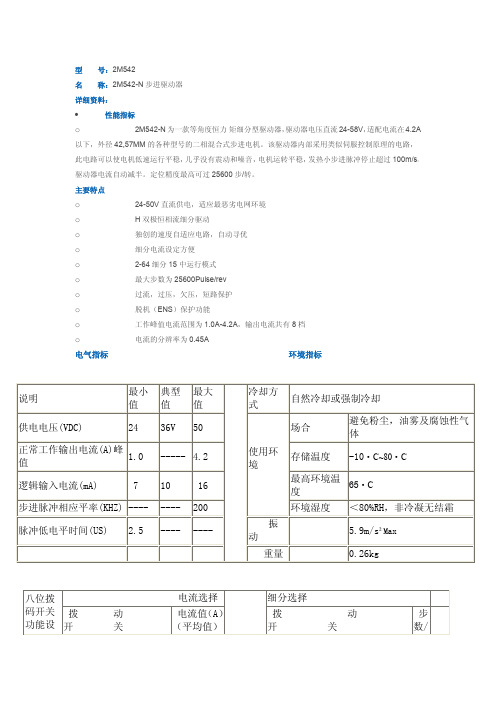

DM542型细分型两相混合式步进电机驱动器,采用直流18-50V供电,适合驱动电压为18V-50V,电流小于4.0A外径42-86mm的两相混合式步进电机。
此驱动器采用交流伺服驱动器的电流环进行细分控制,电机的转矩波动很小,低速运行很平稳,几乎没有振动和噪音。
高速时力矩也大大高于其它二相驱动器,定位精度高,广泛用于雕刻机,数控机床,包装机械等分辨率要求较高的设备上!
主要特点
1 平均电流控制,两相正弦电流驱动输出
2 直流18~50V供电
3 光电隔离信号输入/输出
4 有过压、欠压、过流、相间短路保护功能
5 十五档细分和自动半流功能
6 八档输出相电流设置
7 具有脱机命令输人端子
8 电机的扭矩与它的转速有关,而与电机每转的步数无关
9 高启动转速
10.高速力矩大
一、电气参数
输入电压直流18~50V输入
输入电流小于4安培
输出电流 1.0A~4.2A
功耗功耗:80W;内部保险:6A
温度工作温度-10~45℃;存放温度-40℃~70℃
湿度不能结露,不能有水珠
气体禁止有可燃气体和导电灰尘
重量200克
二、控制信号接口
图1是驱动器的接线原理图
1、控制信号定义
PLS/CW+:步进脉冲信号输入正端或正向步进脉冲信号输入正端PLS/CW-:步进脉冲信号输入负端或正向步进脉冲信号输入负端DIR/CCW+:步进方向信号输入正端或反向步进脉冲信号输入正端DIR/CCW-:步进方向信号输入负端或反向步进脉冲信号输入负端ENA+:脱机使能复位信号输入正端
ENA-:脱机使能复位信号输入负端。

HT D542两相数字式步进电机驱动器使用前请认真阅读本手册用户使用手册常州合泰电机电器股份有限公司■ 简介● 两相数字式步进电机驱动器HTD542具有高速大转矩特性 供电电压可达 50VDC 静止时电流自动减半正弦波电流控制技术电机发热低● ● ● ● 光电隔离差分信号输入,响应频率最高200K 细分精度高达十六种,2倍及5倍细分均可选择具有过压、欠压,过流等保护功能可进行脉冲/方向或双脉冲模式切换● ●● HTD542两相步进电机驱动器是有极高可靠性的两相步进电机驱动器,是当前行业在售产品中返修率最低的一款产品。
得益于其优秀的过流和过压保护拓扑电路,使其即使在极高转速及适度过压情况下,仍可启动自保护以确保不被损坏。
HTD542两相步进电机驱动器适配两相42,57,60的各类两相混合式步进电机。
■ 电气性能及环境指标电气参数● 环境指标●驱动器参数最小值典型值最大值单位输入电压184850VDC 驱动电流 1.0- 4.2A 输入脉冲频率1-200K Hz 输入脉冲宽度250-5E+8ns 绝缘电阻500--M Ω冷却方式自然冷却或强制冷却使用场合避免粉尘,油污及腐蚀性气体工作环境温度0~40℃最高环境湿度90%RH (无结露)存储温度-10 ~70℃ 最大振动5.9m/S2 max■ 机械尺寸及安装图状态指示灯控制信号拨码开关设定电动机连接ENA -ENA+DIR -DIR +PUL-P UL+S W8S W7S W6S W5S W4S W3S W2S W1B -B+A+A -RED/GR ■ 驱动器接口与接线示意图电源及电机接线●● 控制信号接口控制信号示例图●名称功能GND -电源负极V+电源正极:DC18V ~50V A+两相电机A 相。
A+、A-互调,可变换电机运转方向A -B+两相电机B 相。
B+、B-互调,可变换电机运转方向B -名称功能PUL+脉冲控制信号:脉冲下降沿有效,脉冲电压5-24V,为了可靠响应,脉冲宽度大于1.5μS。

YKE2405M-2A数字型二合一步进驱动器使用手册版本:V1.0深圳研控自动化科技股份有限公司目录目录 (2)版本修订历史 (1)前言 (2)第1章概述 (3)1.1 产品介绍 (3)1.2 特性 (3)1.3 应用领域 (3)1.4 产品命名规则 (4)第2章性能指标 (5)2.1 电气特性 (5)2.2 使用环境 (5)第3章安装 (6)3.1 安装尺寸 (6)3.2 安装方法 (6)第4章驱动器端口与接线 (7)4.1 接线示意图 (7)4.2 端口定义 (8)4.2.1 状态指示灯 (8)4.2.2 控制信号输入/输出端口 (8)4.2.3 电源输入/电机输出端口 (9)4.3 输入/输出端口操作 (9)4.4 拨码开关设定 (11)4.4.1驱动器电流设置 (11)4.4.2驱动器细分设置 (11)4.4.3锁机电流设置 (12)第5章适配电机 (13)5.1 电机尺寸 (13)5.1.1 42mm两相开环电机 (13)5.1.2 57mm两相开环电机 (14)5.2 技术参数 (14)5.3 电机接线图 (15)第6章报警排除 (16)第7章一般故障排除方法 (17)第8章保修及售后服务 (18)8.1保修 (18)8.2售后服务 (18)YKE2405M-2A使用手册V1.0 版本修订历史版本修订历史YKE2405M-2A使用手册V1.0 前言前言感谢您使用本公司步进驱动器。
在使用本产品前,请务必仔细阅读本手册,了解必要的安全信息、注意事项以及操作方法等。
错误的操作可能引发极其严重的后果。
声明本产品的设计和制造不具备保护人身安全免受机械系统威胁的能力,请用户在机械系统设计和制造过程中考虑安全防护措施,防止因不当的操作或产品异常造成事故。
由于产品的改进,手册内容可能变更,恕不另行通知。
用户对产品的任何改装我公司将不承担任何责任。
阅读时,请注意手册中的以下标示:第1章概述1.1 产品介绍YKE2405M-2A是基于全新一代32位DSP技术的高性能一拖二步进驱动器,驱动电压为DC 20V-50V,配备两路电机输入,可以同时适配电流连续输出在4.0A以内,法兰为42/57mm的两相开环步进电机,且适配不同电机时驱动器可通过拨码对电流和细分进行设置。

DM542说明书1
DM542 4.2A电机驱动说明书DM542是本公司专门针对⽤户⽤量较⼤,同时要求性价⽐较⾼
的客户应⽤,对于电机存在有震动,要求噪⾳⼜⼩的⽤户的⾸选1供电电压可达48VDC
2输出电流峰值可达4.2A
3光隔离,输⼊可以共阴,共阳,差分信号,脉冲最⾼响应频率200KHz 4低速零震动,且噪⾳及⼩
5抗⼲扰能⼒强,在电⽹恶劣的环境⾥,可以实现⾼精度定位
应⽤领域;⾃动包装机,点胶机,雕刻机等⾃动化设备,对于以前⽤到有震动和噪⾳较⼤的⽤户有明显改善
应⽤范围:所有法兰盘为42,57机⾝长度在80毫⽶以下所有电机,以及86短机⾝
电⽓特性:
驱动器功能说明
信号接⼝
PUL+和 PUL-为控制脉冲信号正端和负端;DIR+和DIR-为⽅向信号正端和负端;ENA+和 ENA-为使能信号的正端和负端。
5V-24V通⽤.⽆需加电阻
电机接⼝
A+和 A-接步进电机A相绕组的正负端;B+和B-接步进电机B相绕组的正负端。
当A、B两相绕组调换时,可使电机⽅向反向。
电源接⼝
采⽤直流电源供电,⼯作电压范围建议为20-50VDC,电源功率⼤于100W,根据实际使⽤情况开看,输⼊在不超过DC40V 为合适选择
指⽰灯
驱动器有红绿两个指⽰灯。
其中绿灯为电源指⽰灯,当驱动器上电后绿灯常亮;红灯为故障指⽰灯,当出现过压、过流故障时,故障灯常亮。
故障清除后,红灯灭。
当驱动器出现故障时,只有重新上电和重新使能才能清除故障。
上⼀页下⼀页。
2HSS858H-N低压数字式简易步进伺服驱动器使用说明书地址:深圳市光明区马田街道佳裕科技园B栋电话:*************26502268传真:*************E-mail:*******************本手册的所有内容,著作财产权归深圳市杰美康机电有限公司所有,未经深圳市杰美康机电有限公司许可,任何单位或个人不得随意仿制、拷贝、撰抄。
本手册无任何形式的担保、立场表达或其它暗示。
如有本手册所提到的产品的信息,所引起的直接或间接的资料流出,导致利益损失后果,深圳市杰美康机电有限公司与所属员工不承担任何责任。
除此以外,本手册提到的产品及其资料仅供参考,内容如有更新,恕不另行通知。
版权所有,不得翻印。
深圳市杰美康机电有限公司版本编写核准V1.02研发部研发部目录一、产品简介 (4)1、概述 (4)2、技术特点 (4)3、应用领域 (5)二、技术指标 (6)1、电气、机械和环境指标 (6)2、机械安装尺寸图 (6)3、加强散热方式 (7)三、故障代码 (8)四、驱动器接口与接线介绍 (8)1、接口定义 (10)2、控制信号接口电路图 (13)3、控制信号时序图 (15)4、控制信号模式设置 (15)5、编码器接线 (15)五、驱动器参数设置 (17)六、参数调节方法 (20)1、按键操作方法 (22)七、典型应用接线图 (23)八、常见问题及故障处理 (21)1、电源灯不亮 (21)2、上电亮红灯报警 (21)3、运行转动一小角度后亮红灯报警 (21)4、脉冲输入后不转动 (21)一、产品简介1、概述2HSS858H-N是一款完美融入伺服技术的新型简易步进伺服驱动器。
该步进伺服驱动器采用了最新的32位DSP,融合了先进的功角闭环控制算法,相比传统步进驱动器,能够最大程度地避免步进电机丢步问题,并有效地抑制电机温升,明显地降低电机振动,极大地增强电机高速性能。
该驱动器成本是交流伺服系统的50%,同时适配电机尺寸兼容传统步进电机,方便客户替代升级。
Website: Email:*******************User’s ManualForDM542Fully Digital Stepper Drive Attention: Please read this manual carefully before using the drive!DM542Digital two-phase stepper driver 一、Introduction1. OverviewDM542 is the new digital stepping motor driver of our company. It adopts the latest 32-bit DSP digital processing technology. The driver control algorithm uses advanced variable current technology and advanced frequency conversion technology.The driver has low heat generation, small motor vibration and stable operation. Users can set any subdivision within 200~51200 and any current value within the rated current, which can meet the application needs of most occasions. With built-in micro-segmentation technology, even in the case of low subdivision, high subdivision can be achieved, and the operation at low, medium and high speeds is smooth and the noise is extremely small.The parameter internal power-on auto-tuning function is integrated in the drive, which can automatically generate optimal operating parameters for different motors to maximize the performance of the motor.2. Features3. Application fieldSuitable for all kinds of small and medium-sized automation equipment and instruments, such as: engraving machine, marking machine, cutting machine, laser phototypesetting, plotter, CNC machine tool, automatic assembly equipment, etc. It is especially effective in applications where users expect small noise and high speed.二、Electrical, mechanical and environmental indicators1. Electrical indexDescription DM542Min Typical Max UnitOutput current 0.1 - 4.2 AInput supply voltage 24 36 50 VDCControl signal input current 6 10 16 mAControl signal interface level 4.5 5 28 VdcInput signal minimum pulse width 1.5 - - usStep pulse frequency 0 - 200 KHz Insulation resistance 100 MΩ2. Operating Environment and other SpecificationsCooling Natural Cooling or Forced coolingOperatingnvironmentEnvironment Avoid dust, oil fog and corrosive gasesAmbient Temperature -5℃~+50℃Humidity 40 ~90%RHVibration 5.9m/s2MAXStorage Temperature -20℃~80℃weight about 300 g●New 32-bit DSP technology●Ultra low vibration noise●Built-in high subdivision●Parameter power-on auto-tuning function●Variable current control makes the motor heat greatly reduced●The current is automatically halved at rest●4,6,8 line two-phase stepper motor●Optically isolated differential signal input●The impulse response frequency can reach up to 500KHz (factory default 160KHz) ●The current setting is convenient, and can be arbitrarily selected between 0.1-4.2A.●The subdivision setting range is 200-51200●With overvoltage, undervoltage, overcurrent protection3. Mechanical Specifications (unit: mm [inch])*Recommend use side mounting for better heat dissipation4. Elimination of Heat1)Driver’s reliable working temperature should be <70℃(158℉), and motor working temperature should be <80℃(176℉);2)It is recommended to use automatic idle-current mode, namely current automatically reduce to 50% when motor stops, so as to reduce driver heating and motor heating;3)It is recommended to mount the driver vertically to maximize heat sink area. Use forced cooling method to cool the system if necessary.三、Pin Assignment and Description1. Pin Assignment 1)Control signal interfaceName functionPUL+ Pulse signal: pulse rising edge is valid; PUL is 4.5~28Vdc at high level and 0~0.5V at low level. In order to respond reliably to pulse signals, the pulse width should begreater than 1.5μs。
SS57步进伺服电机驱动器的技术参考手册一、产品简介1.1概述SS57步进伺服电机驱动器是东莞市一能机电技术有限公司全新推出的SS混合伺服系列产品,采用行业最新的Cotex-M4 ARM 核处理器,主频高达80MHz,使得驱动器对外部响应频率最高可达500KHz,用以适配57步进伺服电机,从而使电机具有高精度,快响应,不失步,停止时绝对静止等优良特性,是当前业内同类产品中特性表现极其优异的一款产品。
1.2 SS57特点◆全新Cotex-M4 ARM核技术32位处理器◆主频高达80MHZ◆电机最高空载运行速度达4000转◆电机响应频率最高达500KHZ以上◆输出电流最高达7A ◆细分高达25600◆输入电压最高75VDC ◆双脉冲及脉冲加方向模式切换◆报警复位功能◆脉冲,方向,使能兼容5-24V输入◆丰富的报警及运行显示讯号◆失步报警输出功能1.3 技术参考步进伺服电机驱动器最近几年来在机器视觉,线性模组,广告展示设备,线束设备,自动锁螺丝机等要求快速定位,频繁快速启动以及中高速长距离运动的场合得到了迅速的推广和应用。
东莞市一能机电技术有限公司经过两年多的精心设计,于近期推出的最新款SS步进伺服电机驱动器系列产品,采用行业最新的ARM核M4控制器,主频高达80MHZ,使得电机响应频率最高可达2MHZ,闭环步进电机的空载最高转速可达4000转/分钟或以上!1.4 功能示意图二、电气、机械和环境指标2.1 SS57电气指标2.2 SS57使用环境及参数2.3 SS57机械安装图单位:毫米(mm)图1.安装尺寸图三、SS57步进伺服电机驱动器接口和接线介绍3.1 SS57步进伺服电机驱动器接口与接线示意图3.2 电源输入接口3.3 电机及编码器接口3.4 控制信号接口四、电流、细分、功能拨码开关设定4.1 细分设置拨码4.2 初始方向选择拨码电机初始转动方向通过SW5进行设定。
ON:电机逆时针旋转,OFF:电机顺时针旋转(出厂默认)电机顺时针旋转,当电机顺时针运转时,驱动器LED指示灯按照绿-黄-红-蓝-绿循环闪烁。
步进电机驱动器F542
F542 外观图
产品概述
F542数字型步进驱动器采用最新32位DSP技术,用户可以设置40000内的16档细分以及额定电流内的4档电流值,能够满足大多数场合的应用需要。
由于采用内置微细分技术,即使在低细分的条件下,也能够达到高细分的效果,低中高速运行都很平稳,噪音超小。
驱动器内部集成了参数自动整定功能,能够针对不同电机自动生成最优运行参数,最大限度发挥电机的性能。
最大可承受电压50V,最大输出电流4.2A。
主要应用领域:适合各种中小型自动化设备和仪器,例如:雕刻机、打标机、切割机、激光照排、绘图仪、数控机床、自动装配设备等。
中科伺服以市场为导向,为工控行业提供品质可靠、操作简单、性能优良的产品。
以渠道销售为主,为客户提供专业、快捷的技术服务。
产品现有全系列数字步进驱动器,数字闭环步进驱动器,高响应伺服驱动器,直流无刷驱动器,多功能运动控制器,关节机器人控制器,驱动控制一体机,高精密军工级伺服转台等产品和方案。
参数设置
电流设置
F542驱动器采用六位拨码开关设定细分精度、电流。
详细描述如下:
SW1 SW2 电流(A )
OFF OFF 1.4 OFF ON 2.8 ON
OFF 3.5 ON
ON
4.2
安装尺寸
细分设置
SW3 SW4 SW5 SW6 脉冲/转 ON ON ON ON 200 ON ON ON OFF 400 ON ON OFF ON 800 ON ON OFF OFF 1000 ON OFF ON ON 1600 ON OFF ON OFF 2000 ON OFF OFF ON 3200 ON OFF OFF OFF 4000 OFF ON ON ON 5000 OFF ON ON OFF 6400 OFF ON OFF ON 8000 OFF ON OFF OFF 10000 OFF
OFF ON ON 12800 OFF OFF ON OFF 16000 OFF OFF OFF ON 20000 OFF
OFF
OFF
OFF
40000
驱动器功能说明
驱动器功能 操作说明
输出电流设定 由 SW1-SW2两个拨码开关来设定驱动器输出电流,其输出电流共有4档具体输出电流的设定,请按驱动器面版图说明。
微步细分数设定 由 SW3-SW6 四个拨码开关来设定驱动器微步细分数,其共有 16 档微步细分。
用户可在运行中设定微步细分。
具体微步细分数的设定,请按驱动器面版图说明。
自动半流功能 脉冲串停止后约 0.1 秒左右电流自动减至一半左右(实际值的60%),发热量理论上减至 36%。
信号接口
PUL +和 PUL -为控制脉冲信号正端和负端;DIR +和 DIR -为方向信号正端和负端;ENA +和 ENA -为使能信号的正端和负端。
电机接口 A +和 A -接步进电机 A 相绕组的正负端;B +和 B -接步进电机 B 相绕组的正负端。
当 A 、B 两相绕组调换时,可使电机方向反向,A+、A-调换,B+、B-调换也可以使电机方向反向,不同绕组禁止接在不同相端子上。
电源接口 采用直流电源供电,具有电源反接保护功能。
工作电压范围建议为20-40VDC ,供电电源功率需大于 100W 。
指示灯
驱动器有红绿两个指示灯。
其中绿灯为电源指示灯,当驱动器上电后绿灯常亮;红灯为故障指示灯,当出现过流故障时,故障灯常亮。
故障清除后,红灯灭。
当驱动器出现故障时,只有重新上电才能清除故障。
安装说明
驱动器的外形尺寸为:118×75.5×33mm ,安装孔距为 109mmmm 。
既可以卧式和立式安装,建议采用立式安装。
安装时,应使其紧贴在金属机柜上以利于散热。