AUO友达液晶显示屏电路图5
- 格式:pdf
- 大小:171.14 KB
- 文档页数:5
4.3 单片机与液晶显示电路接口电路设计采用液晶显示可以使显示信息多样化,降低系统的功耗。
本节介绍常用的 MDLS点阵字符型液晶显示模块及LMA97S005AD点阵图形型液晶显示模块接口电路及程序设计。
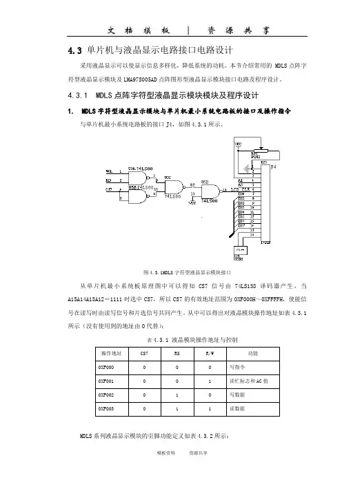
4.3.1 MDLS点阵字符型液晶显示模块模块及程序设计1. MDLS字符型液晶显示模块与单片机最小系统电路板的接口及操作指令与单片机最小系统电路板的接口J4,如图4.3.1所示。
图4.3.1MDLS字符型液晶显示模块接口从单片机最小系统板原理图中可以得知CS7信号由74LS138译码器产生,当A15A14A13A12=1111时选中CS7,所以CS7的有效地址范围为0XF000H~0XFFFFH,使能信号在读写时由读写信号和片选信号共同产生。
从中可以得出对液晶模块操作地址如表4.3.1所示(没有使用到的地址由0代替):表4.3.1 液晶模块操作地址与控制操作地址CS7 RS R/W 功能0XF000 0 0 0 写指令0XF001 0 0 1 读忙标志和AC值0XF002 0 1 0 写数据0XF003 0 1 1 读数据MDLS系列液晶显示模块的引脚功能定义如表4.3.2所示:表4.3.2 MDLS系列液晶显示模块的引脚功能定义引脚号符号状态功能1 Vss 电源地2 Vdd +5V逻辑3 V0 电源液晶驱动电源4 RS 输入寄存器选择 1:数据; 0:指令5 R/W 输入读写操作选择 1:读;0:写6 E 输入使能信号(MDLS未用,符号NC)7 DB0 三态数据总线8 DB1 三态数据总线9 DB2 三态数据总线10 DB3 三态数据总线11 DB4 三态数据总线12 DB5 三态数据总线13 DB6 三态数据总线14 DB7 三态数据总线(MSB)MDLS字符型液晶显示模块指令集如下所示:(1) 清屏功能:清DDRAM和AC值。
RS R/W DB7 DB6 DB5 DB4 DB3 DB2 DB1 DB00 0 0 0 0 0 0 0 0 1(2) 归位功能:AC=0,光标,画面归HOME位。


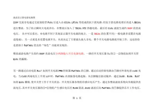
液晶显示器电源电路图220V交流市电通过交流保险管F101后进入由CXl01、LFl01等组成的抗干扰电路,经抗干扰电路处理后再进入BDl01进行整流。
为了防止瞬间大电流冲击,在整流后加入了THl01 NTC热敏电阻,最后经C101滤波生成约300V的直流电压。
从中可以看出,本电路不同于其他显示器开关电源的地方,一是THl01的位置不同(一般电路多设置在电源进线端),另一点就是未设置电源开关,从而决定了只要插头接人市电,整个开关电源电路就开始工作,这也恰恰是借助于FAN7601优良的“绿色”功能来实现的。
整流滤波电路产生的约300V直流电压分两路输入开关电源电路,一路经开关变压器T1的①一②绕组加到开关管Q101的漏极。
另一路通过启动电阻R117加到开关电源PWM控制器FAN7601的①脚,通过启动控制电路由⑦脚对外部电容c108充电,当C108两端电压上升到11V时,FAN7601内部振荡电路起振,从⑥脚输出驱动脉冲,通过D103、R106、R107加到Q101栅极,使开关管工作于开关状态。
开关变压器各绕组有感应电压产生,通过各整流滤波系统向负载提供直流电压。
其中开关变压器的③-④绕组产生感应电压经R105限流、D102滤波后向FAN7601的⑦脚提供芯片工作电压,第 1 页启动控制电路关断①脚的电流输入。
第 2 页在以往的开关电源维修中,尽管采用启动电阻功率比较大但依然是易损元件之一,而且发热量也比较大,实际上就是由于通电后启动电阻一直有电流通过的原因。
而在这款电源中,启动电阻却采用了一个0Ω的贴片元件,是明显区别于其他电路的,这里我们学习到新型“绿色电源芯片”内部都设有一个启动开关,一旦电源达到正常工作状况(启动过程结束),就会切断启动电阻器,这样便可省去一大部分的功率损耗。
其电路本身的故障率也接近于零该机稳压控制电路主要由U101、光电耦合器PC201、精密稳压器件U201(KIA431)及取样电阻R205、R211、R214、R210等组成。
![[初三数学]AOC193Sw液晶维修手册电路图](https://uimg.taocdn.com/aa5c49f1915f804d2a16c172.webp)
[初三数学]AOC193Sw液晶维修手册电路图ServiceServiceServiceHorizontal Frequency30- 83 kHzTABLE OF CONTENTSDescription Page Description PageANY PERSON ATTEMPTING TO SERVICE THIS CHASSIS MUST FAMILIARIZE HIMSELF WITH THE CHASSIS AND BE AWARE OF THE NECESSARY SAFETY PRECAUTIONS TO BE USED WHEN SERVICING ELECTRONIC Table Of Contents (1)Revision List (2)1. Monitor Specification (4)2.L C D M o n i t o rD e s c r i p t i o n (5)3. Operation Instruction (6)3.1. Gene ral Instructions (6)3.2. Control Buttons (6)3.3 Adjusting the Picture (7)4.I n p u t/O u t p u tS p e c i f i c a t i o n (10)4.1.I n p u t S i g n a lC o n n e c t o r (10)4.2.F a c t o r y P r e s e t D i s p l a yM o d e s (10)5.2. Electrical Block Diagram (15)6. Schematic (17)6.1 Main Board (17)6.2 Power Board (23)7.P C BLayout (26)7.1 Main Board (26)7.2 Powe r Board (28)8.Maintainability (32)8.1.E q u i p m e n t s a n d T o o l sR e q u i r e m e n t (32)8.2.T r o u b l eShooting (33)9.W h i t e-B a l a n c e,L u m i n a n c eEQUIPMENT CONTAINING HIGH VOLTAGES.Revision ListImportant Safety NoticeProper service and repair is important to the safe, reliable operation of all AOC Company Equipment. The service procedures recommended by AOC and described in this service manual are effective methods of performing service operations. Some of these service operations require the use of tools specially designed for the purpose. The special tools should be used when and as recommended.It is important to note that this manual contains various CAUTIONS and NOTICES which should be carefully read in order to minimize the risk of personal injury to service personnel. The possibility exists that improper service methods may damage the equipment. It is also important to understand that these CAUTIONS and NOTICES ARE NOT EXHAUSTIVE. AOC could not possibly know, evaluate and advise the service trade of all conceivable ways in which service might be done or of the possible hazardous consequences of each way. Consequently, AOC has not undertaken any such broad evaluation. Accordingly, a servicer who uses a service procedure or tool which is not recommended by AOC must first satisfy himself thoroughly that neither his safety nor the safe operation of the equipment will be jeopardized by the service method selected.Hereafter throughout this manual, AOC Company will be referred to as AOC.WARNINGUse of substitute replacement parts, which do not have the same, specified safety characteristics might create shock, fire, or other hazards.Under no circumstances should the original design be modified or altered without written permission from AOC. AOC assumes no liability, express or implied, arising out of any unauthorized modification of design. Servicer assumes all liability.FOR PRODUCTS CONTAINING LASER:DANGER-Invisible laser radiation when open AVOID DIRECT EXPOSURE TO BEAM.CAUTION-Use of controls or adjustments or performance of procedures other than those specified herein may result in hazardous radiation exposure.CAUTION -The use of optical instruments with this product will increase eye hazard.TO ENSURE THE CONTINUED RELIABILITY OF THIS PRODUCT, USE ONLY ORIGINAL MANUFACTURER'S REPLACEMENT PARTS, WHICH ARE LISTED WITH THEIR PART NUMBERS IN THE PARTS LIST SECTION OF THIS SERVICE MANUAL.Take care during handling the LCD module with backlight unit-Must mount the module using mounting holes arranged in four corners.-Do not press on the panel, edge of the frame strongly or electric shock as this will result in damage to the screen.-Do not scratch or press on the panel with any sharp objects, such as pencil or pen as this may result in damage to the panel.-Protect the module from the ESD as it may damage the electronic circuit (C-MOS).-Make certain that treatment person’s body is grounded through wristband.-Do not leave the module in high temperature and in areas of high humidity for a long time.-Avoid contact with water as it may a short circuit within the module.-If the surface of panel becomes dirty, please wipe it off with a soft material. (Cleaning with a dirty or rough cloth may damage the panel.)1. Monitor Specification2. LCD Monitor DescriptionThe LCD Monitor will contain a main board, a power board, which house the flat panel control logic, brightness control logic and DDC.The power board will provide AC to DC Inverter voltage to drive the backlight of panel and the main board chips each voltage.3. Operation Instructions3.1 General InstructionsPress the power button to turn the monitor on or off. The other control knobs are located at front panel of the monitor. By changing these settings, the picture can be adjusted to your personal preferences.-The power cord should be connected.-Connect the video cable from the monitor to the video card.- Press the power button to turn on the monitor. The power indicator will light up.3.2 Control Buttons•Power Button:Press this button to switch ON/OFF of monitor’s power.•MENU / ENTER:Active OSD menu or function adjust confirm or Exit OSD menu when in Brightness/Contrast OSD status.•Contrast:Adjust contrast or function adjust.•Brightness:Adjust brightness or function adjust.•Auto Adjust button / Exit:1. When OSD menu is in active status, this button will act as EXIT-KEY(EXIT OSD menu).2. When OSD menu is in off status, press this button over 2 seconds to activate the Auto Adjustmentfunction.The Auto Adjustment function is used to set the HPos, VPos, Clock and Focus.•Power Indicator:Blue — Full Power mode.Orange — Active-off mode.OSD Lock Function: To lock the OSD, press and hold the MENU button while the monitor is off and then press power button to turn the monitor on. To un-lock the OSD - press and hold the MENU button while the monitor is off and then press power button to turn the monitor on.NOTES•Do not install the monitor in a location near heat sources such as radiators or air ducts, or in a place subject to direct sunlight, or excessive dust or mechanical vibration or shock.•Save the original shipping carton and packing materials, as they will come in handy if you ever have to ship your monitor.•For maximum protection, repackage your monitor as it was originally packed at the factory.•To keep the monitor looking new, periodically clean it with a soft cloth. Stubborn stains may be removed with a cloth lightly dampened with a mild detergent solution. Never use strong solvents such as thinner, benzene, or abrasive cleaners, since these will damage the cabinet. As a safety precaution, always unplug the monitor before cleaning it.3.3 Adjust the Picture1. Press the MENU-button to activate the OSD window.2. Press or to navigate through the functions. Once the desired function is highlighted, press theMENU-button to activate it. If the function selected has a sub-menu, press or again to navigate through the sub-menu functions. Once the desired function is highlighted, press MENU-button to activate it.3. Press or to change the settings of the selected function.4. To exit and save, select the exit function. If you want to adjust any other function, repeat steps 2-3.Main MenuItemMainMenuIconSub MenuItemSub MenuIconDescriptionAdjustRangeReset Value LuminanceContrast Contrast from Digital-register. 0-100Recall CoolContrast ValueBrightness Backlight Adjustment 0-100Recall CoolBrightnessValueImageSetupFocusAdjust Picture Phase to reduceHorizontal-Line noise0-100 Do Auto ConfigClockAdjust picture Clock to reduceVertical-Line noise.0-100 Do Auto ConfigImagePositionH. PositionAdjust the horizontal position ofthe picture.0-100 Do Auto Config V. PositionAdjust the vertical position of thepicture.0-100 Do Auto Config Color Temp. Warm N/ARecall warm Color Temperaturefrom EEPROM.N/AThe ColorTemperature willCool N/A Recall cool Color Temperaturefrom EEPROM.N/Abe set to Cool.The User R/G/Bvalue (default is100) will not beModified byReset function.sRGB N/A Recall sRGB Temperature from EEPROM.N/AUser / Red Red Gain from Digital-register. 0-100User/GreenGreen Gain from Digital-register. 0-100 User / Blue Blue Gain from Digital-register. 0-100Auto Config (Analog-Onl y Model) Yes N/AAuto Adjust the H/V Position,Focus and Clock of picture.N/A N/A No N/ADo not execute Auto Config,return to main menu.N/A N/AOSD Setup H. PositionAdjust the horizontal position ofthe OSD.0-100 50 V. PositionAdjust the vertical position of theOSD.0-100 50 OSDTimeoutAdjust the OSD timeout. 10-120 10Language Language N/A Select the language you like N/A The Language will be set toEnglish.Information InformationN/AShow the resolution, H/Vfrequency and input port ofcurrent input timing.N/A N/AReset Yes N/AClear each old status ofAuto-configuration and set thecolor temperature to Cool.N/A N/A No N/ADo not execute reset, return tomain menu.N/A N/AExit N/A N/A Exit OSD N/A N/A4. Input/Output SpecificationPin Signal Pin Signal1 Red Video 9 5V2 Green Video 10 Detect cable3 Blue Video 11 Monitor Ground4 GND 12 DDC-Serial Data5 GND 13 H- Sync6 GND-R 14 V- Sync7 GND-G 15 DDC-Serial Clock8 GND-BVGA connector layout4.2. Factory Preset Display Modes4.3. Panel SpecificationM190A1-L02 is a 19” wide TFT Liquid Crystal Display module with 4 CCFL Backlight unit and 30 p ins2ch-LVDS interface. This module supports 1440 x 900 WXGA+ mode and can display 16.2M colors. The inverter module for Backlight is not built in.4.3.1 General Feature- Super Wide viewing angle.- Super High contrast ratio- Super fast response time- High color saturation- WXGA+ (1440 x 900 pixels) resolution- DE (Data Enable) only mode- LVDS (Low Voltage Differential Signaling) interface- RoHS Compliance4.3.2 Mechanical Information4.3.3 Optical Characteristics Test ConditionsOptical Specification5. Block Diagram 5.1 Software Flow ChartREMARK:5.2 Electrical Block Diagram 5.2.1 Main Board19" LCD Color Monitor AOC 193SW5.2.2 Inverter / Power Board206. Schematic6.1 Main Board21TSU16/56AK SCHEMATIC22H4W3.2R MH1WA24CK LITE6AdjBA CK4TOUCH PANELPOWERA14 BC1.840.1uF/16VA340.1uF3904BP OWE R BTSU16/56AK FOR MYSON512 SWICHB26Sunday, February 06, 2005TitleSize Document Number RevDate:Sheet ofSS14R203A44 onPanel_5V/3.3V6C3.34 H2232425R 327R325R336C2C306R346C314C312220pFR335VC R345R331R349R309R350C308R318C305C310R317R313C301NCR 32656788C307CC I_S EL 6C3042C309DV I NPUTBTSU16/56AK FOR MYSON512 SWITCHC 36Sunday, February 06, 2005TitleSize Document NumberRevDate:SheetofCLK _DD C2R332C317R344R348R347R341NC R343DV I_D ET 6R323C4013077R40127PB4PB1PA[0..9]4PB8PANEL INTERFACEBTSU16/56AK FOR MYSON512 SWITCHA 56Sunday, February 06, 2005TitleSiz e Document NumberRevDate:SheetofPA1PA8LVA0P LVB1M LVB3M PB7PA2LVBCKP PB2LVBCKM LVA2M LVA3M CN503PA[0..9]PB3PB0LVA1M PB6PA7LVB0MPA6LVB1P LVACKP PB5PA9LVA0M PA3PB9PB[0..9]4LVA2P R502PA4LVB0P LVB2P PA0LVA1P LVB3P PA5LVACKM LVA3P LVB2M PB[0..9]2829R623BR651_GC608CON16A35NCQ602PMBS 390622pFLeftR608U601R640NC 0.1uFC6094C6070.001uFVolume R639ER 0.1uFC611R60610K 1/16WR6096.2 Power BoardL103ID PC1942SET1P(715G1299-5)A1.POWERA O C (T o p V i c t o r y ) E l e c t r o n i c s C o ., L t d .A 21Thursday , July 20, 2006Title Siz e Document NumberRevDate:SheetofDIMis signal GNDis power GNDCON102CONN 95G8014 6512L201R2377. PCB Layout 7.1 Main Board7.2 Power Board Inverter BoardAdapter Board8. Maintainability8.1 Equipments and Tools Requirement1. Multi-meter.2. Oscilloscope.3. Pattern Generator.4. DDC Tool with an IBM Compatible Computer.5. Alignment Tool.6. LCD Color Analyzer.7. Service Manual.8. User Manual.8.2 Trouble Shooting 8.2.1 Main BoardNo powerNo picture (LED orange)White screen8.2.2 Power/Inverter Board 1.) No power2.) No Backlight9. White- Balance, Luminance AdjustmentApproximately 30 minutes should be allowed for warm up before proceeding White-Balance adjustment.1. How to do the Chroma-7120 MEM. Channel settingA. Reference to chroma 7120 user guideB. Use “SC” key and “NEXT” key to modify x yY value and use “ID” key to modify theTEXT description Following is the procedure to do white-balance adjust2. Setting the color temp. you wantA. MEM.CHANNEL 3 (7800 color):7800 color temp. parameter is x = 296 ±20, y = 311 ±20, Y = 180 cd/m2 ,B. MEM.CHANNEL 4 (6500 color):6500 color temp. parameter is x = 313±20, y = 329 ±20, Y = 180 cd/m23. Into factory mode of 193SWFirstly, turn off the power and remove the power plug, then press the menu key and plug in at the same time, finally, press the menu again will activate the factory mode, the factory OSD will be at the left top of the screen.4. Bias adjustment:Set the Contrast to 50; Adjust the Brightness to 80.5. Gain adjustment:Move cursor to “-F-” and press MENU keyA. Adjust C2 (7800) color-temperature1. Switch the Chroma-7120 to RGB-Mode (with press “MODE” button)2. Switch the MEM. Channel to Channel 3 (with up or down arrow on chroma 7120)3. The LCD-indicator on chroma 7120 will show x = 296 ±20, y = 311 ±20, Y = 180 cd/m24. Adjust the RED of color1 on factory window until chroma 7120 indicator reached the value R=1005. Adjust the GREEN of color1 on factory window until chroma 7120 indicator reached the value G=1006. Adjust the BLUE of color1 on factory window until chroma 7120 indicator reached the value B=1007. Repeat above procedure (item 4,5,6) until chroma 7120 RGB value meet the tolerance =100±2B. Adjust C1 (6500) color-temperature1. Switch the chroma-7120 to RGB-Mode (with press “MODE” button)2. Switch the MEM.channel to Channel 4(with up or down arrow on chroma 7120)3. The LCD-indicator on chroma 7120 will show x = 313 ±20, y = 329 ±20, Y = 180 cd/m24. Adjust the RED of color3 on factory window until chroma 7120 indicator reached the value R=1005. Adjust the GREEN of color3 on factory window until chroma 7120 indicator reachedthe value G=1006. Adjust the BLUE of color3 on factory window until chroma 7120 indicator reached the value B=1007. Repeat above procedure (item 4,5,6) until chroma 7120 RGB value meet the tolerance =100±2C. Turn the Power-button off to quit from factory mode.19"LCD Color Monitor AOC 190SW4710. Monitor Exploded ViewNo Description Part NO. No Description Part NO. No Description Part NO. 1 BEZEL 034G6346AAS 1B 7 SHIELD Q15G6335 2 13HINGE BRACKET015G6233 1 2 KEY PAD077GB800SOB G8 MYLAR 052G6025 11946 14 HINGE 037G6055 1 3 PANEL-SIDE-BKT 015G6232 2 9MYLAR052G6025 11980 15 STAND 034G1546 GM B 4 PANEL 750GLM90A1211N 10 MAIN FRAME 015G6231 4 16 CLAMP 033G4695 1 C 5 MAIN BOARD CBPC5MM4WBQP 11 REAR COVER 034G6269 GM 2B 17 BASE T34G6203 GM 2B 6POWER BOARDADPC1260AEP12 RUBBER012G6204 118 FOOT PORON012G 394 311. BOM List T95MM4HBWCA2NS。
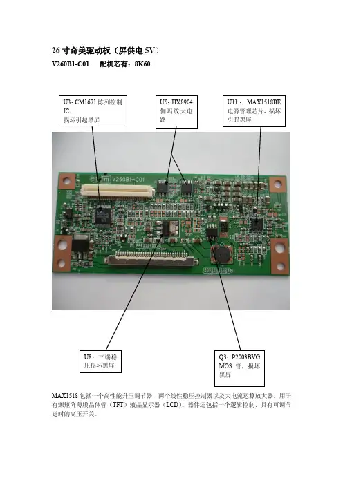
V260B1-C01 配机芯有:8K60MAX1518包括一个高性能升压调节器、两个线性稳压控制器以及大电流运算放大器,用于有源矩阵薄膜晶体管(TFT )液晶显示器(LCD )。
器件还包括一个逻辑控制、具有可调节延时的高压开关。
V315B3-C01 配机芯有8M19TPS65161的20、21、22:电源输入Vin; 此IC 与外围电配合可产生几路电压:VGH :23V V AAP :13.5V VGL :负5V VDA : VON : VOFF : VLOGIC :3.3V 等32寸奇美屏驱动板(屏供电12V )V320B1-C03 配机芯有:8M10FP5138:电源管理芯片,升压、降压、升降压转换IC ,驱动能力强,可以很好的提供LCD 屏正负偏设计方案,各组电压输出稳定,还可以适用于7—12寸LED 液晶屏背光升压垣流驱动。
有短路保护、开路保护、软启动功能,工作电压1.8—15V ,工作电流5.5mA 。
1脚:FB 反馈 2脚:SCP 保护/软启动 3脚:VCC 供电 4脚:CTL 控制 5脚:OUT 输出 6脚:GND 地 7脚:OSC 振荡 8脚:COMP 补偿V296W1-C1,X7 配机芯有:8TG5V296W1-C1逻辑板电路主要有三大部分组成:1.由U4(CM2651B-KQ )为核心的时序与逻辑控制电路,主要功能是将串行的LVDS 信号变成并行的控制信号,用于薄腊晶体管的控制或驱动;2.由U7—U11(HX8904TA 、HX8904SA )为核心的伽玛放大电路,主要是将伽玛信号进行适当的放大,控制薄膜晶体管,实现画面对比度的调整;3.由UP1(FA3269A V )为核心的DC-DC 变换电路,主是是将主板送来的5V 供电变成VGH (20V )、VDA (15V )、VGL (—5V )、V5V (5V )、VDD (3.3V )等等,用于屏驱动供电,此逻辑板损坏的最多的地方就是这部分,易损坏元件为UP1、QP5、DP3、UP2、RP37、LP2电感等等。