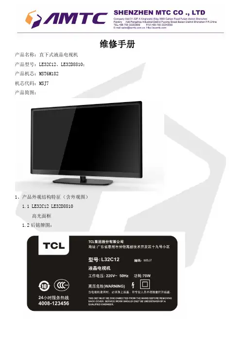
液晶显示屏电路图
- 格式:pdf
- 大小:211.50 KB
- 文档页数:7


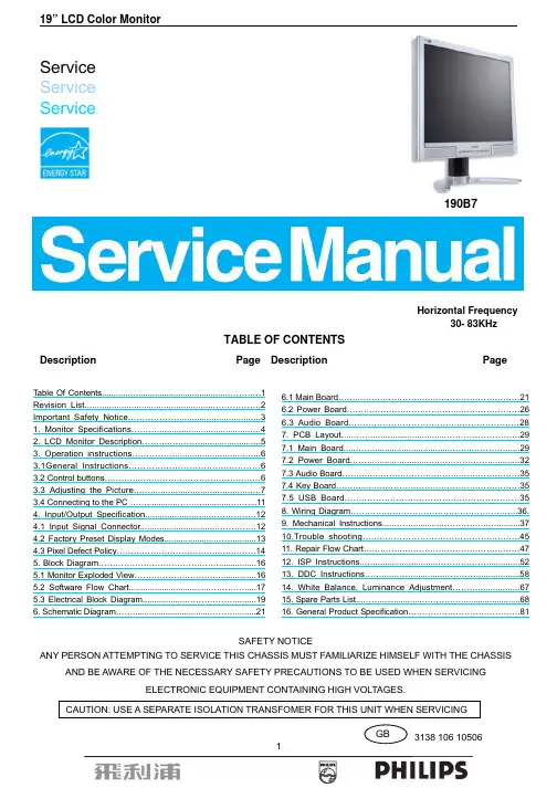
ServiceService Service190B7Horizontal Frequency30- 83KHzTABLE OF CONTENTSDescription Page Description PageSAFETY NOTICEANY PERSON ATTEMPTING TO SERVICE THIS CHASSIS MUST FAMILIARIZE HIMSELF WITH THE CHASSISAND BE AWARE OF THE NECESSARY SAFETY PRECAUTIONS TO BE USED WHEN SERVICINGELECTRONIC EQUIPMENT CONTAINING HIGH VOLTAGES.Table Of Contents (1)Revision List (2)Important Safety Notice (3)1. Monitor Specifications...................................................42. LCD Monitor Description..............................................53. Operation instructions.................................................63.1General Instructions..............................................63.2 Control buttons.. (6)3.3 Adjusting the Picture (7)3.4 Connecting to the PC (11)4. Input/Output Specification...........................................124.1 Input Signal Connector..............................................124.2 Factory Preset Display Modes......................................134.3 Pixel Defect Policy..................................................145. Block Diagram...........................................................165.1 Monitor Exploded View..............................................165.2 Software Flow Chart....................................................175.3 Electrical Block Diagram.............................................196. Schematic Diagram (21)6.1 Main Board (21)6.2 Power Board (26)6.3 Audio Board (28)7. PCB Layout....................................................................297.1 Main Board.....................................................................297.2 Power Board.................................................................327.3 Audio Board................................................................357.4 Key Board..................................................................357.5 USB Board.............................................................358. Wiring Diagram............................................................36.9. Mechanical Instructions......................................................3710.Trouble shooting.......................................................4511. Repair Flow Chart........................................................4712. ISP Instructions...............................................................5213. DDC Instructions............................................................5814. White Balance, Luminance Adjustment..........................6715. Spare Parts List..................................................................6816. General Product Specification. (81)Revision ListVersion Release Date Revision HistoryA00 April.10, 2006 Initial release, Draft VersionImportant Safety NoticeProper service and repair is important to the safe, reliable operation of all Philips Company** Equipment. The service procedures recommended by Philips and described in this service manual are effective methods of performing service operations. Some of these service operations require the use of tools specially designed for the purpose. The special tools should be used when and as recommended.It is important to note that this manual contains various CAUTIONS and NOTICES which should be carefully read in order to minimize the risk of personal injury to service personnel. The possibility exists that improper service methods may damage the equipment. It is also important to understand that these CAUTIONS and NOTICES ARE NOT EXHAUSTIVE. Philips could not possibly know, evaluate and advise the service trade of all conceivable ways in which service might be done or of the possible hazardous consequences of each way. Consequently, Philips has not undertaken any such broad evaluation. Accordingly, a servicer who uses a service procedure or tool which is not recommended by Philips must first satisfy himself thoroughly that neither his safety nor the safe operation of the equipment will be jeopardized by the service method selected.* * Hereafter throughout this manual, Philips Company will be referred to as Philips.WARNINGUse of substitute replacement parts, which do not have the same, specified safety characteristics may create shock, fire,or other hazards.Under no circumstances should the original design be modified or altered without written permission from Philips. Philipsassumes no liability, express or implied, arising out of any unauthorized modification of design.Servicer assumes all liability.FOR PRODUCTS CONTAINING LASER:DANGER-Invisible laser radiation when open. AVOID DIRECT EXPOSURE TO BEAM.CAUTION-Use of controls or adjustments or performance of procedures other than those specified herein may result in hazardous radiation exposure.CAUTION -The use of optical instruments with this product will increase eye hazard.TO ENSURE THE CONTINUED RELIABILITY OF THIS PRODUCT, USE ONLY ORIGINAL MANUFACTURER'S REPLACEMENT PARTS, WHICH ARE LISTED WITH THEIR PART NUMBERS IN THE PARTS LIST SECTION OF THIS SERVICE MANUAL.Take care during handling the LCD module with backlight unit-Must mount the module using mounting holes arranged in four corners.-Do not press on the panel, edge of the frame strongly or electric shock as this will result in damage to the screen. -Do not scratch or press on the panel with any sharp objects, such as pencil or pen as this may result in damage to thepanel.-Protect the module from the ESD as it may damage the electronic circuit (C-MOS).-Make certain that treatment person’s body is grounded through wristband.-Do not leave the module in high temperature and in areas of high humidity for a long time.-Avoid contact with water as it may a short circuit within the module.-If the surface of panel becomes dirty, please wipe it off with a soft material. (Cleaning with a dirty or rough cloth may damage the panel.)Screen type Active matrix - TFT LCDPanel Type LM190E03-TLBDSize 19"Pixel pitch 0.294mm(H) x 0.294mm(V)Separate Sync TTL level, input impedance 2.2k OHM terminateHorizontal Frequency 30kHz – 83kHzLCD PanelVertical refresh rate 56Hz - 76Hz15pin D-SUBInput Connector24pin DVI1280 x 1024 at 76Hz (analog input)Maximum Resolution1280 x 1024 at 76Hz (digital input)Display Colors 16.2 MVideo dot rate 140 MHzRecommended Resolution 1280 x 1024 at 60Hz (digital input)Plug & Play VESA DDC2BPower Consumption Power on: < 40 W Power off: < 1 WInput Video Signal 0.7 Vp-p, input impedance, 75 ohm @DC Tilt -5°~ 25°Active Viewing Area Horizontal: 376.3mm;Vertical: 301.1 mm Power Source 100-240 VAC, 50/60 HzEnvironmental Considerations Operating Temp: 5°C to 40°C Storage Temp.: -20°C to 60°C Relative Humidity: 20%-80%Weight (Net) 6.14kgCabinet color 190B7CG: Light Gray 190B7CB: Black190B7CS: SilverThe LCD MONITOR will contain a main board, PWPC board, keypad board, which house the flat panel control logic, brightness control logic and DDC.The power board will provide AC to DC Inverter voltage to drive the backlight of panel and the main board chips each voltage.3. Operation instructions3.1 General InstructionsPress the power button to turn the monitor on or off. The other control buttons are located at front panel of the monitor. By changing these settings, the picture can be adjusted to your personal preferences.- The power cord should be connected.- Connect the video cable from the monitor to the video card.- Press the power button to turn on the monitor, the power indicator will light up.3.2 Control ButtonsFront ViewRear View3.3 Adjusting the PictureThis is a feather in all Philips LCD monitors. It allows an end user to adjust screen performance of the monitors directly through an on-screen instruction window. The user interface provides user-friendliness and ease-of-use when operating the monitor.When you press the button on the front control of your monitor, the On-Screen Display (OSD) main controlswindow will pop up and you can then start making adjustments to your monitor’s various features. Use theor the keys to make your adjustments.The OSD treeBelow is an overall view of the structure of the On-Screen Display. You can use this as a reference when you want to work your way around the different adjustments later on.3.4 Connecting to the PC1) Connect the power cord to the back of the monitor firmly. (Philips has pre-connected) VGA cable for the first installation.)2) Connect to PC(a) Turn off your computer and unplug its power cable.(b) Connect the monitor signal cable to the video connector on the back of your computer.(c) Plug the power cord of your computer and your monitor into a nearby outlet.(d) Connect the PC audio cable to the audio connector on the back of your computer.(e) USB plug(1) Connect USB upstream port on monitor and the USB port on PC with a USB cable.(2) The USB downstream port is now ready for any USB device to plug in.(f) Turn on your computer and monitor. If the monitor displays an image, installation is complete.4. Input/Output Specification4.1 Input Signal Connector4.1.1 D-SUB connectorPin NO. Description Pin NO. Description1. Red Video input 9. DDC +5V2. Green Video input (SOG) 10. Logic GND3. Blue Video input 11. Ground4. Sense (GND) 12. Serial data line (SDA)5. Cable Detect (GND) 13. H.sync/H + V.sync6. Red Video Ground 14. V.Sync7. Green Video Ground 15. Data Clock Line (SCL)8. Blue Video GroundVGA Connector layout4.1.2 DVI connectorNo. Description No. Description PinPinconnect1. TMDS data 2-13. No2. TMDS data 2+14. +5V Power3. TMDS data 2/4 Shield 15. GND (for +5V)4. No connect 16. Hot Plug Detectconnect 17. TMDS data 0-5. No6. DDCClock 18. TMDS data 0+7. DDC Data 19. TMDS data 0/5 Shield8. No Connect 20. No connect9. TMDS data 1-21. Noconnect10. TMDS data 1+22. TMDS Clock Shield11. TMDS data 1/3 Shield 23. TMDS Clock +12. Noconnect 24. TMDS Clock -Digital Connector4.2 Factory Preset Display Modes4.3 Pixel Defect Policy19” LCD Color Monitor165. Block Diagram5.1 Monitor Exploded View1) MCU Initializes.2) Is the EEprom blank?3) Program the EEprom by default values.4) Get the PWM value of brightness from EEprom.5) Is the power key pressed?6) Clear all global flags.7) Are the AUTO and SELECT keys pressed?8) Enter factory mode.9) Save the power key status into EEprom.Turn on the LED and set it to green color. Scalarinitializes.10) In standby mode?11) Update the lifetime of back light.12) Check the analog port, are there any signals coming?13) Does the scalar send out an interrupt request?14) Wake up the scalar.15) Are there any signals coming from analog port?16) Display "No connection Check Signal Cable" message. And go into standby mode after the message disappears.17) Program the scalar to be able to show the coming mode.18) Process the OSD display.19) Read the keyboard. Is the power key pressed?5.3 Electrical Block Diagram 5.3.1 Main Board5.3.2 Inverter/Power Board6. Schematic Diagram 6.1 Main Board715G1767-16.2 Power Board715G1813-1L902CN853CONNCONNCN833CONNCN851CONN6.3 Audio Board715G1763-17. PCB Layout 7.1 Main Board715G1767-17.2 Power Board715G1813-17.3 Audio Board715G1763-17.4 Key Board 715G1766-17.5 USB Board715G1764-18. Wiring Diagram9. Mechanical InstructionsSteps of dismantling base stand from base columnStep 1: Place the monitor face down on a smooth surface as Fig 1. Be careful to avoid scratch and injury during the uninstallation. Meanwhile, it is need to avoid pressing the control key.Fig1Step 2: Insert a sheet, as Fig 2.2, to the base stand as Fig 2.1.The sheet’s dimension is about 5cm(L) x 1cm(W) x 1mm(D).Fig2.1 Fig2.2Step 3: Put out the base emphatically as Fig 3, then you can disjoin the base from the stand.Fig3Step 4:Turn the stand, then pull out the hinge cover as Fig 4.The hinge coverFig4Step 5: Pull out the stand cover emphatically as Fig 5.Step6: Unfasten the four screws on the hinge as Fig 6, then dismantle base stand from base column.Fig 7Back View as Fig.1Fig.1 2. Remove hinge cover as Fig.2.Remove the hinge cover as Fig.2Fig.2Pull out the stand cover emphatically asFig.3 4. Remove base stand as Fig.4Remove the four screws as Fig.7 to remove the base stand.Fig.4\Remove the three screws to remove the back cover as Fig.5.Fig.56. Remove the shields of the main board and power board as Fig.6.Remove the 8 screws as Fig.6 to remove the shields.Fig.67. Remove the main board、audio board and the power board. as Fig.7Remove the 10 screws as Fig.7 to remove the main board、audio board and the power board.Fig.78. Remove the main frame as Fig.8.Remove the 4 screws as Fig.8 to remove the main frame.Fig.810. Trouble ShootingThis page deals with problems that can be corrected by a user. If the problem still persists after you have tried these solutions, contact Philips customer service representative.11. Repair Flow Chart (1). No Power(4). Keypad BoardPower/Inverter Board No power。
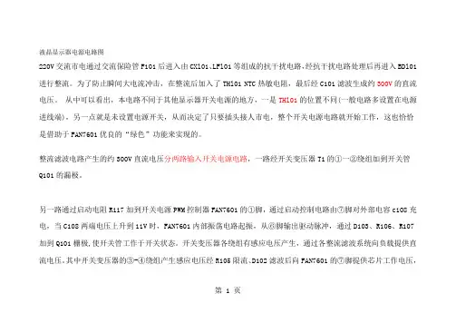
液晶显示器电源电路图220V交流市电通过交流保险管F101后进入由CXl01、LFl01等组成的抗干扰电路,经抗干扰电路处理后再进入BDl01进行整流。
为了防止瞬间大电流冲击,在整流后加入了THl01 NTC热敏电阻,最后经C101滤波生成约300V的直流电压。
从中可以看出,本电路不同于其他显示器开关电源的地方,一是THl01的位置不同(一般电路多设置在电源进线端),另一点就是未设置电源开关,从而决定了只要插头接人市电,整个开关电源电路就开始工作,这也恰恰是借助于FAN7601优良的“绿色”功能来实现的。
整流滤波电路产生的约300V直流电压分两路输入开关电源电路,一路经开关变压器T1的①一②绕组加到开关管Q101的漏极。
另一路通过启动电阻R117加到开关电源PWM控制器FAN7601的①脚,通过启动控制电路由⑦脚对外部电容c108充电,当C108两端电压上升到11V时,FAN7601内部振荡电路起振,从⑥脚输出驱动脉冲,通过D103、R106、R107加到Q101栅极,使开关管工作于开关状态。
开关变压器各绕组有感应电压产生,通过各整流滤波系统向负载提供直流电压。
其中开关变压器的③-④绕组产生感应电压经R105限流、D102滤波后向FAN7601的⑦脚提供芯片工作电压,第 1 页启动控制电路关断①脚的电流输入。
第 2 页在以往的开关电源维修中,尽管采用启动电阻功率比较大但依然是易损元件之一,而且发热量也比较大,实际上就是由于通电后启动电阻一直有电流通过的原因。
而在这款电源中,启动电阻却采用了一个0Ω的贴片元件,是明显区别于其他电路的,这里我们学习到新型“绿色电源芯片”内部都设有一个启动开关,一旦电源达到正常工作状况(启动过程结束),就会切断启动电阻器,这样便可省去一大部分的功率损耗。
其电路本身的故障率也接近于零该机稳压控制电路主要由U101、光电耦合器PC201、精密稳压器件U201(KIA431)及取样电阻R205、R211、R214、R210等组成。
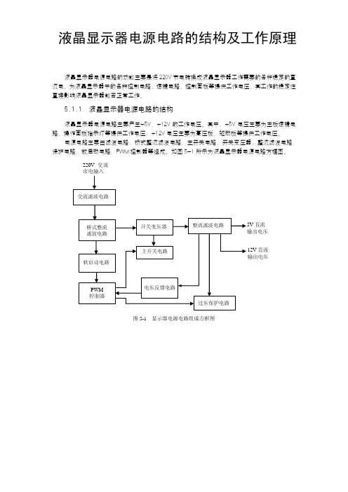
液晶显示器电源电路的结构及工作原理液晶显示器电源电路的功能主要是将220V 市电转换成液晶显示器工作需要的各种稳定的直流电,为液晶显示器中的各种控制电路、逻辑电路、控制面板等提供工作电压,其工作的稳定性直接影响液晶显示器能否正常工作。
5.1.1 液晶显示器电源电路的结构液晶显示器电源电路主要产生+5V、+12V 的工作电压。
其中,+5V 电压主要为主板逻辑电路、操作面板指示灯等提供工作电压;+12V 电压主要为高压板、驱动板等提供工作电压。
电源电路主要由滤波电路、桥式整流滤波电路、主开关电路、开关变压器、整流滤波电路、保护电路、软启动电路、PWM 控制器等组成。
如图5-1所示为液晶显示器电源电路方框图。
220V 交流市电输入直流 12V 直流 输出电压图5-1 显示器电源电路组成方框图其中,交流滤波电路的作用是消除市电中的高频干扰(线性滤波电路一般由电阻、电容和电感组成);桥式整流滤波电路的作用是将220V交流电变成310V左右的直流电;开关电路的作用是将310V左右的直流电通过开关管和开关变压器后,变成不同幅度的脉冲电压;整流滤波电路的作用是将开关变压器输出的脉冲电压经过整流和滤波后变成负载需要的基本电压5V和12V;过压保护电路的作用是尽量避免因负载异常或其他原因导致的开关管损坏或开关电源损坏;PWM 控制器的作用是控制开关管的切换,根据保护电路的反馈电压控制电路。
5.1.2 液晶显示器电源电路的工作原理液晶显示器的电源电路一般采用开关电路方式,此电源电路将交流220V输入电压经过整流滤波电路变成直流电压,再由开关管斩波和高频变压器降压,得到高频矩形波电压,最后经整流滤波后输出液晶显示器各个模块所需要的直流电压。
下面以AOC LM 729液晶显示器为例讲解液晶显示器电源电路的工作原理。
AOC LM 729液晶显示器的电源电路主要由交流滤波电路、桥式整流电路、软启动电路、主开关电路、整流滤波电路、过压保护电路等组成,其电源电路实物图和电路原理图如图5-2所示。
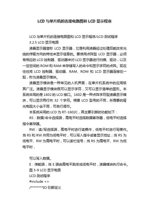
LCD与单片机的连接电路图和LCD显示程序LCD与单片机的连接电路图和LCD显示程序/LCD测试程序3.2.5 LCD显示电路液晶显示器简称LCD显示器,它是利用液晶经过处理后能改变光线的传输方向的特性来显示信息的。
要使用点阵型LCD显示器,必须有相应的LCD控制器、驱动器来对LCD显示器进行扫描、驱动,以及一定空间的ROM和RAM来存储写入的命令和显示字符的点阵。
现在往往将LCD控制器、驱动器、RAM、ROM和LCD显示器连接在一起,称为液晶显示模块。
液晶显示模块是一种常见的人机界面,在单片机系统中的应用极其广泛。
液晶显示模块既可以显示字符,又可以显示简单的图形。
本系统采用的是1602的LCD接口。
1602是一种点阵字符型液晶显示模块,可以显示两行共32个字符。
根据LCD型号的不同,所需要的背光电阻大小会不同,可自行调节。
本系统采用的LCD为RT-1602C,其主要引脚的功能如下:RS:数据/命令选择端,高电平时选择数据寄存器,低电平时选择指令寄存器。
RW:读/写选择端,高电平时进行读操作,低电平时进行写操作。
当RS和RW共同为低电平时,可以写入指令或者显示地址;当RS为低电平、RW为高电平时,可以读忙信号;当RS为高电平、RW为低电平时,可以写入数据。
E:使能端,当E端由高电平跳变成低电平时,液晶模块执行命令。
图3-9 LCD显示电路LCD测试程序#include <>/********IO引脚定义*********************************************************** /sbit LCD_RS=P2^7;//定义引脚sbit LCD_RW=P2^6;sbit LCD_E=P2^5;/********宏定义*********************************************************** / #define LCD_Data P0#define Busy 0x80 //用于检测LCD状态字中的Busy标识/********数据定义*********************************************************** **/ unsigned char code uctech[] = {"Happy every day"};unsigned char code net[] = {""};/********函数声明*********************************************************** **/ void WriteDataLCD(unsigned char WDLCD); //写数据void WriteCommandLCD(unsigned char WCLCD,BuysC); //写命令unsigned char ReadDataLCD(void); //读数据unsigned char ReadStatusLCD(void); //读状态void LCDInit(void); //初始化void DisplayOneChar(unsigned char X, unsigned char Y, unsigned char DData); //相应坐标显示字节内容void DisplayListChar(unsigned char X, unsigned char Y, unsigned char code *DData); //相应坐标开始显示一串内容void Delay5Ms(void); //延时void Delay400Ms(void); //延时/***********主函数开始********************************************************/ void main(void){Delay400Ms(); //启动等待,等LCD讲入工作状态LCDInit(); //初始化Delay5Ms(); //延时片刻(可不要)DisplayListChar(0, 0, uctech);DisplayListChar(1, 5, net);ReadDataLCD(); //测试用句无意义while(1);}/***********写数据********************************************************/ void WriteDataLCD(unsigned char WDLCD){ReadStatusLCD(); //检测忙LCD_Data = WDLCD;LCD_RS = 1;LCD_RW = 0;LCD_E = 0; //若晶振速度太高可以在这后加小的延时LCD_E = 0; //延时LCD_E = 1;}/***********写指令********************************************************/ void WriteCommandLCD(unsigned char WCLCD,BuysC) //BuysC为0时忽略忙检测{if (BuysC) ReadStatusLCD(); //根据需要检测忙LCD_Data = WCLCD;LCD_RS = 0;LCD_RW = 0;LCD_E = 0;LCD_E = 0;LCD_E = 1;}/***********读数据********************************************************/ unsigned char ReadDataLCD(void){LCD_RS = 1;LCD_RW = 1;LCD_E = 0;LCD_E = 0;LCD_E = 1;return(LCD_Data);}/***********读状态*******************************************************/ unsigned char ReadStatusLCD(void){LCD_Data = 0xFF;LCD_RS = 0;LCD_RW = 1;LCD_E = 0;LCD_E = 0;LCD_E = 1;while (LCD_Data & Busy); //检测忙信号return(LCD_Data);}/***********初始化********************************************************/ void LCDInit(void){LCD_Data = 0;WriteCommandLCD(0x38,0); //三次模式设置,不检测忙信号Delay5Ms();WriteCommandLCD(0x38,0);Delay5Ms();WriteCommandLCD(0x38,0);Delay5Ms();WriteCommandLCD(0x38,1); //显示模式设置,开始要求每次检测忙信号WriteCommandLCD(0x08,1); //关闭显示WriteCommandLCD(0x01,1); //显示清屏WriteCommandLCD(0x06,1); //显示光标移动设置WriteCommandLCD(0x0C,1); //显示开及光标设置}/***********按指定位置显示一个字符*******************************************/void DisplayOneChar(unsigned char X, unsigned char Y, unsigned char DData){Y &= 0x1;X &= 0xF; //限制X不能大于15,Y不能大于1if (Y) X |= 0x40; //当要显示第二行时地址码+0x40;X |= 0x80; //算出指令码WriteCommandLCD(X, 0); //这里不检测忙信号,发送地址码WriteDataLCD(DData);}/***********按指定位置显示一串字符*****************************************/void DisplayListChar(unsigned char X, unsigned char Y, unsigned char code *DData)unsigned char ListLength;ListLength = 0;Y &= 0x1;X &= 0xF; //限制X不能大于15,Y不能大于1while (DData[ListLength]>=0x20){ //若到达字串尾则退出if (X <= 0xF){ //X坐标应小于0xFDisplayOneChar(X, Y, DData[ListLength]); //显示单个字符ListLength++;X++;}}}/***********短延时********************************************************/ void Delay5Ms(void){unsigned int TempCyc = 5552;while(TempCyc--);}/***********长延时********************************************************/ void Delay400Ms(void){unsigned char TempCycA = 5;unsigned int TempCycB;while(TempCycA--){TempCycB=7269;while(TempCycB--);}LCD与单片机连接的引脚并不是固定的,如有不同只需要在程序里改一下引脚即可。

LCD12864系列点阵型液晶显示模块使用说明书一、OCM12864液晶显示模块概述1.OCM12864液晶显示模块是128×64点阵型液晶显示模块,可显示各种字符及图形,可与CPU直接接口,具有8位标准数据总线、6条控制线及电源线。
采用KS0107控制IC。
2.外观尺寸:113×65×11mm(ocm12864-1), 93×70×10mm(ocm12864-2)78×70×10mm(ocm12864-3),3.视域尺寸:×38.8mm(ocm12864-1) ×38mm(ocm12864-2),64×44mm(ocm12864-3)4.重量:大约g补充说明:外观尺寸可根据用户的要求进行适度调整。
二、最大工作范围1、逻辑工作电压(Vcc):~2、电源地(GND):0V3、LCD驱动电压(Vee):0~-10V4、输入电压:Vee~Vdd5、工作温度(Ta):0~55℃(常温) / -20~70℃(宽温)6、保存温度(Tstg):-10~65℃三、电气特性(测试条件 Ta=25,Vdd=+/1、输入高电平(Vih):2、输入低电平(Vil):3、输出高电平(Voh):4、输出低电平(Vol):5、工作电流:四、接口说明12864-3A接口说明表管脚号管脚电平说明CODE: R/W D/I DB7 DB6 DB5 DB4 DB3 DB2 DB1 DB0L H D7D6D5D4D3D2D1D0功能:写数据到DD RAM,DD RAM是存储图形显示数据的,写指令执行后Y地址计数器自动加1。
D7-D0位数据为1表示显示,数据为0表示不显示。
写数据到DD RAM前,要先执行“设置页地址”及“设置列地址”命令。
7、读显示数据CODE: RS R/W DB7 DB6 DB5 DB4 DB3 DB2 DB1 DB0H H D7D6D5D4D3D2D1D0功能:从DD RAM读数据,读指令执行后Y地址计数器自动加1。