PARSTAT4000电化学综合测试仪
- 格式:doc
- 大小:956.00 KB
- 文档页数:6

TGA 4000热失重分析仪使用手册珀金埃尔默仪器(上海)有限公司1`0Pyris Software S*2.1ECÊVEÄ用户可以从Windows 2000、Windows XP以及Windows 7操作系统(Pyris 11版本以上)的开始菜单中调用Pyris软件。
软件安装过程中可选择将“Pyris软件管理器”(Pyris Manager)放置于开始菜单中或系统桌面上。
软件的所有工具条,包括缩放工具条、状态面板等均采用浮动式窗口设计,用户可根据自身偏好改变它们的位置。
可以通过双击想要拖动的工具条得到相应的浮动窗口,然后按住该窗口的标题栏拖至您想要的位置。
其中控制面板可以固定于显示窗口的左边界或者右边界。
操作系统开始菜单中的Pyris软件文件夹包含如下组件:Pyris P¬C Pyris Advanced Software用户可通过该选项选择性的安装高阶软件(Install Advanced Software),例如步进扫描(MTDSC)或者Pyris分解动力学软件,以及安装Pyris增强型安全组件(Install Enhanced Security)。
Pyris Pyris Help该选项包含基于WinHelp的多媒体演示资料(Pyris MultiMedia Presentations)以及帮助文档(Pyris Software Help)。
多媒体演示资料以视频方式指导用户如何制样或Pyris软件包含数据分析组件可用于处理热分析仪采集的数据。
该数据分析软件具有通用性,任何通过Pyris软件连接的PerkinElmer热分析仪器均可使用该软件处理数据。
此外,软件可同时处理多组数据。
Pyris C1u)<Pyris Manager用户可通过Pyris软件管理器进入仪器控制界面,该界面可同时显示所有与主机相连的热分析设备。
此外,管理器还如下选项和功能:数据分析软件,监控仪器运行状况,配置TGA 4000参数,Pyris帮助文档以及关闭选项。

恒压电沉积Pt-Fe合金催化剂及在PEMFC阴极的应用赵文文;张华;李梅【摘要】利用循环伏安法探究Pt与Fe共沉积的还原电位,并在此电位下在多孔碳布表面恒压电沉积制备Pt-Fe合金,研究其作为质子交换膜燃料电池(PEMFC)阴极催化剂的电催化活性.通过X射线衍射(XRD)、扫描电子显微镜(SEM)及场发射扫描电子显微镜(FESEM)、能量色散谱(EDS)、循环伏安(CV)、单电池极化、电化学交流阻抗谱(EIS)等测试技术对所得催化剂进行物理及电化学性能表征.实验表明,在0.075V电位下可还原得到Pt-Fe合金,其颗粒在碳布表面呈空心球状且分散均匀;共沉积时间对Pt-Fe合金催化剂成分组成有显著的影响,随着时间的增加,合金中Pt 与Fe原子比增加,Fe相对含量下降.Fe可与Pt形成稳定的合金催化剂,显著提高铂对氧还原的催化活性.电沉积30 min制得的合金催化剂具有最佳的催化活性.【期刊名称】《无机材料学报》【年(卷),期】2013(028)011【总页数】6页(P1217-1222)【关键词】循环伏安;还原电位;Pt-Fe合金;氧还原;质子交换膜燃料电池【作者】赵文文;张华;李梅【作者单位】南京工业大学材料科学与工程学院,南京210009;南京工业大学材料科学与工程学院,南京210009;南京工业大学材料科学与工程学院,南京210009【正文语种】中文【中图分类】TM911质子交换膜燃料电池 (PEMFC)作为未来可移动设备的理想动力源之一[1-3], 已成为国内外的研究热点, 探寻具有较高催化活性的阴极电催化剂一直是该领域研究的重点。
目前, 低温燃料电池阴极催化剂的有效活性成分仍以贵金属铂为主[4], 但铂作为稀有贵金属成本较高, 因此需要在不降低催化性能的前提下寻求来源广泛、价格低廉的电催化剂替代材料, 以减少或取代贵金属铂的使用。
目前, 对阴极催化剂的研究主要集中在铂基合金催化剂和非贵金属催化剂, 其中铂基合金具有较高的催化活性及化学稳定性[5], 成为研究重点。

基于电化学阻抗的航空有机涂层加速老化动力学规律研究谭晓明;王鹏;王德;钱昂【摘要】bjective To study the accelerated aging dynamic rules of organic coating.Methods Accelerated aging testing spectrum of organic coating was prepared and equivalent accelerated aging test of 0 ~ 9a was carried out according to conditions and features of environment in which the plane will serve.The electrochemical impedance of coating specimens after aging tests was tested by virtue of the PARSTAT 4000 electrochemical workstation.Results Bode diagram,equivalent circuit,porosity,water absorption and electrochemical impedance of organic coatings with different aging period were obtained.Dynamic rules of accelerated aging test were characterized.Conclusion Low-frequency impedance |Z|0.01 can be used as index for evaluation of anti-corrosion coating.The aging process coating can be divided into three stages of early,middle and later,corresponding to three different equivalent circuits.%目的研究有机涂层的加速老化动力学规律.方法针对某飞机实际服役环境条件特点,编制有机涂层加速老化试验谱,开展0~9 a的当量加速老化试验.借助PARSTAT 4000电化学工作站,测试老化试验后涂层试件的电化学阻抗值.结果得到了不同老化周期有机涂层的Bode图、等效电路、孔隙率、吸水率和电化学阻抗,表征了加速试验条件下的老化动力学规律.结论低频阻抗|Z|0.01可以作涂层防腐蚀性能的评价指标,涂层老化过程大致可分为初期、中期和后期三个阶段,分别对应三个不同等效电路.【期刊名称】《装备环境工程》【年(卷),期】2017(014)001【总页数】4页(P5-8)【关键词】加速试验谱;有机涂层;老化;电化学阻抗【作者】谭晓明;王鹏;王德;钱昂【作者单位】海军航空工程学院青岛校区,山东青岛266041;海军驻景德镇航空军事代表室,江西景德镇333001;海军航空工程学院青岛校区,山东青岛266041;海军航空工程学院青岛校区,山东青岛266041【正文语种】中文【中图分类】TG171;V255.5飞机结构表面采用有机涂层隔离金属基体与水、氧气及腐蚀介质等因素的联合作用,达到防止金属基体腐蚀的目的[1—4]。

电化学综合测试系统技术参数设备名称:电化学综合测试系统品牌:(美国)普林斯顿型号:PARSTAT 2273一、技术参数:1、功率放大器*1.1 槽压:±100V1.2 最大电流:±2A(标配)*1.3最大功率:200W1.4 转换速率:≥15V/us1.5 升起时间:<250ns2、差分静电计*2.1输入阻抗:≥ 10e13Ω in parallel with ≤ 5pF2.2 输入偏置电流:<5 pA2.3 最大输入电压:±10V2.4差分:±10V*2.5带宽:-3dB@>15 MHZ3、IR补偿3.1正反馈范围:2000MΩ2Ω(取决于电流幅度)4、电流测量4.1 电流量程:2A-40pA*4.2 电流分辨率:1.2fA4.3 电流准确性:20μA to 2A <0.4% full scale5、交流阻抗测试5.1 频率范围:10uHz――1MHz*5.2最小交流电压幅值:0.1mV RMS5.3扫描:线性或对数6、通讯接口:USB7、软件功能7.1在WINDOWS 环境下运行32位的电化学交流阻抗软件,可进行下述测试:恒电位交流阻抗,恒电流交流阻抗,恒电位下的交流阻抗随时间变化曲线,恒电流下的交流阻抗随时间变化曲线,多波叠加技术。
Mott-Shottky技术:*可以更改参数的设置(下一个频率点,终止频率点,剩余的实验中的数据点数,频率扫描方向)可作单频,多频实验并可实时显示在数据采集期间,可以同时显示一,二,三,四种图形提供Z数学函数提供强有力的特效校正工具,使得每套电化学阻抗系统都有最佳的性能开放的数据库管理多波叠加技术,大大提高测试速度可在同一初始条件下多次连续循环并同时显示开放的Access数据库管理7.2腐蚀测试软件,能完成如下测试并实时显示a. 线性极化曲线b. 阳极极化曲线c. 塔菲尔曲线d. 动电位极化曲线e. 循环极化f. 腐蚀电位随时间的变化曲线g. 恒电流h. 恒电位i. 开路电位j. 腐蚀速率与时间曲线k. 电偶腐蚀l. 电化学噪声*允许同时控制多台恒电位仪*具有电流中断IR补偿功能*可以控制旋转电极的速度,启动/停止7.3 32位数据库管理的循环伏安软件包括:- 线性扫描- 循环伏安- 多重循环- 阶梯循环伏安- 模拟量和数字量扫描7.4阶跃测试软件包括:- 计时电流- 计时电位7.5 脉冲测试软件包括:- 电流脉冲- 电位脉冲- 方波伏安- 差分脉冲伏安- 常规脉冲伏安- 反常规脉冲伏安- 多重循环电位阶跃- 多重循环电流阶跃7.6 配备电化学阻抗等效电路拟合软件一套二、配置清单:1、恒电位/电流仪及阻抗测试仪一套2、仪器控制软件及数据拟合软件一套。

The Viavi Solutions™ T-BERD/MTS-4000 equipped with the Copper Services Module delivers comprehensive copper testing and addresses the distinct requirements of very high-speed digital subscriber line (VDSL) deployment and maintenance. The T-BERD/MTS-4000 is a rugged, modular platform engineered with a 7-inch color display, long battery life, and weather-resistant design for outstanding performance and reliability in the field. The Copper Services Module brings the functionality to the platform that service providers need to mitigate the significant challenge of VDSL rollout and maintenance in various fiber (FTTx) deployments. Traditionally, the copper plant has not been qualified to withstand the stringent needs of VDSL service delivery. The new spectrum that VDSL uses introduces more rigorous and stringent requirements than previously seen in the installed plant. VDSL testing has shown that the plant is susceptible to impulse noise not encountered in the current asymmetric digital subscriber line (ADSL) usage spectrum. In addition, the detection of short bridged taps, which create a much greater impact on VDSL signals than on ADSL signals, becomes more critical in VDSL testing. The T-BERD/MTS-4000 Copper Services Module tests to these standards and more to qualify and troubleshoot the copper for service.The T-BERD/MTS-4000 is easily upgradeable with advanced options that support the industry’s changing technologies and the evolving needs of service installers. Its dynamic configurability allows technicians with varying responsibilities to use it to perform a wide range of tests. Standard Ethernet and universal serial bus (USB) or optional Wireless Fidelity (WiFi) and Bluetooth connections offer flexibility to easily download software and offload captured test data to improve workforce productivity and baseline network performance.Key Featuresy Complete copper testing from POTS through full-spectrum VDSL/VDSL2 up to 30 MHzy Time domain reflectometer (TDR) with time-varying gain (TVG) andauto identificationy Spectral analysis to 30 MHz withone-button zoom to VDSL bands and causes of interferencey Viavi scripting and automated test features that simplify testingy Wideband copper functionality available in combination with ADSL/VDSL2 test modules y Large, color graphical user interface (GUI) with optional touch screen Applicationsy Qualify and troubleshoot twisted pair copper deploymentsy Interoperates with the Viavi UltraFed for single-ended closeout testingy Conducts scripted closeout testing with user-definable pass/fail criteriaT-BERD®/MTS-4000 Multiple Services Test PlatformCopper Services ModuleArchitectureturn-up or trouble isolation.Choose the T-BERD/MTS-4000 Function that Meets Y our Copper Test NeedsThe T-BERD/MTS-4000 offers the broadest and deepest copper access network test capabilities in the industry. It can be configured to deliver: Standard Copper Testing through Full SpectrumThe T-BERD/MTS-4000 offers extended copper testing to quickly and easily pinpoint physical layer problems.Basic features include:y Digital volt-ohm meter (DVOM), measuring AC and DC voltage, current, resistance, and leakagey Ground checky Opens measurementy Signal generator and level meter–Balance–Impedancey Load coil detectiony POTS callsy Caller identification (CLID) testing Using Options, the Copper Module also Offers:y Wideband noise, impulse noise, Transmission Impairment Measurement Set [TIMS]; SNR; cross-talk; return lossy Graphical spectral analysis (up to 30 MHz)y Cable fault location with graphical TDR or resistive fault locator (RFL) Combination Copper/DSLThe Copper Services Module can be configured as a stand-alone copper tester or combined with multiple DSL (xDSL) variants that support:y ADSL1/2/2+y VDSL1, VDSL2y The combination of xDSL and copper functionality provides the capability to install and troubleshoot triple-play services and dispatch copper issues Combined Copper/DSL/Triple-Play TestingThe Copper Services Module can be equipped with an optional xDSL modem and Triple-Play Services software, which adds the capability to analyze data over the optional modem or the native mainframe Ethernet port and provides:y Data throughput and Web browsery VoIP call emulation and monitory IPTV (Video) set top box emulation and monitorThe Right Tool for Today’s Copper Tests The lightweight, rugged, and battery-operated T-BERD/MTS-4000 cost-effectively scales to provide an all-in-one solution for field installation, maintenance, and troubleshooting across a wide range of copper, fiber, and triple-play services test applications. With automation features that improve workforce efficiency, theT-BERD/MTS-4000 is ideally suited to support even the most complex, advanced FTT x networks.© 2015 Viavi Solutions, Inc.Product specifications and descriptions in this document are subject to change without notice.tberd-mts-4000-copper-0115-ds-tfs-tm-ae 30162671 902 0110Contact Us +1 844 GO VIAVI (+1 844 468 4284)To reach the Viavi office nearest you, visit /contacts.SpecificationsOrdering Information。
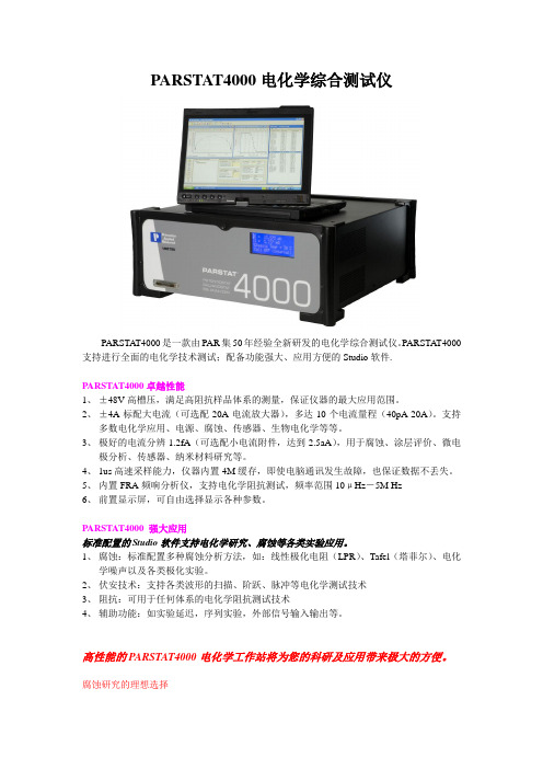
PARSTAT4000电化学综合测试仪PARSTAT4000是一款由PAR集50年经验全新研发的电化学综合测试仪。
PARSTA T4000支持进行全面的电化学技术测试;配备功能强大、应用方便的Studio软件.PARSTAT4000卓越性能1、±48V高槽压,满足高阻抗样品体系的测量,保证仪器的最大应用范围。
2、±4A标配大电流(可选配20A电流放大器),多达10个电流量程(40pA-20A)。
支持多数电化学应用、电源、腐蚀、传感器、生物电化学等等。
3、极好的电流分辨1.2fA(可选配小电流附件,达到2.5aA),用于腐蚀、涂层评价、微电极分析、传感器、纳米材料研究等。
4、1us高速采样能力,仪器内置4M缓存,即使电脑通讯发生故障,也保证数据不丢失。
5、内置FRA频响分析仪,支持电化学阻抗测试,频率范围10μHz-5M Hz6、前置显示屏,可自由选择显示各种参数。
PARSTAT4000 强大应用标准配置的Studio软件支持电化学研究、腐蚀等各类实验应用。
1、腐蚀:标准配置多种腐蚀分析方法,如:线性极化电阻(LPR)、Tafel(塔菲尔)、电化学噪声以及各类极化实验。
2、伏安技术:支持各类波形的扫描、阶跃、脉冲等电化学测试技术3、阻抗:可用于任何体系的电化学阻抗测试技术4、辅助功能:如实验延迟,序列实验,外部信号输入输出等。
高性能的PARSTAT4000电化学工作站将为您的科研及应用带来极大的方便。
腐蚀研究的理想选择●一个电化学工作站的槽压能够决定它能施加给电化学测试系统多大的功率。
高阻抗电解液,如常常在腐蚀研究中遇到的…油,水泥,土壤…很多体系都需要高槽压来克服高阻环境,P4000提供的±48V高槽压对于您未来研究对象的宽范畴来说是非常重要的。
●Studio软件成为腐蚀研究室完成研究的强大工具,线性极化电阻测量和塔菲尔曲线分析(腐蚀电流,极化电阻Rp,腐蚀速度等参数测量)以及各类极化测量,给你直观,方便的操作和满意的结果。
Instruction Manual 4000 Series Digital Portable AnalyzerService Department(800) 458-6153 ext. 121(818) 882-2331 ext. 121FAX(818)341-0642E-mail:************************THIS P AGE INTENTIONALL Y LEFT BLANKTABLE OF CONTENTSSECTION TITLE PAGE1.0 Equipment DescriptionFront Panel 4Rear Panel 6Right Side Panel 7Internal components 8 2.0 Operating InstructionsSetting the Alarm 9Zeroing the Instrument 10Sampling 11 3.0 CalibrationIntroduction 12Sample Bag & Pressurized Cylinder Calibration 14Calibration Procedure 15 4.0 General MaintenanceBattery Life 16Battery Charging & Replacement 16Water loss in Refillable Sensors 18Long Term Storage 23Post Storage Startup 235.0 Troubleshooting 246.0 Warranty 257.0 Return Authorization 268.0 AppendixINTERFERING GAS DATA 27SCRUBBER INFORMATION 31Note:It is not necessary to calibrate the monitor whenreceived from the Interscan or an authorized distributor.All Interscan monitors are calibrated at the factory prior toshipment.The Interscan 4000 Digital series operates on the principle of pullinga sample (Sample draw) through a sensor. The Electrochemicalsensor is manufactured by Interscan. Electrochemical means thatit produces an electrical current proportional to the level of gaspassing through. The large size of the Interscan sensors results inlarger reactive surface area which yields greater sensitivity. Equipment Description(fig. 1)Designation FunctionLCD Display:Indicates gas level when function switch is inZERO, SAMPLE INACTIVE or SAMPLEACTIVE, and battery level when on BAT.TEST A or B.ALARM Light:LED. Flashes ON/OFF when alarm setpoint is exceeded.ALARM SET:25-Turn potentiometer with a screwdriveradjustment. Sets the alarm trip point at thedesired gas level. (low alarm set must begreater than 5% of the full scale).SPAN/CAL:25-Turn potentiometer with a screwdriveradjustment. Sets display to correspond to theconcentration of the calibration gas used forcalibrating the instrument or to the levelspecified on ECS certificate.FUNCTION SWITCH:Rotary switch as follows:OFF:Analyzer power is OFF.SAMPLEINACTIVE:Analyzer power is ON (pump is OFF),Sampling is inactive.SAMPLEACTIVE:Analyzer power and pump are on. Also in thisposition the analyzer is zeroed. Samplemeasurements and calibration areaccomplished in the sample mode.BAT.TEST A:Indicates state of charge of the Nickel-Cadmium (NiCd) batteries on the LCDDisplay. These batteries power the pump &alarm. Recharge if the LCD Display level fallsto or below 100 (ignore decimal point).BAT. TEST B:Indicates state of charge of the “C” sizealkaline batteries on the LCD Display. Thesebatteries power the main circuitry, display andare NOT re-chargeable. Replace if the LCDDisplay level falls to or below 100 (ignoredecimal point). You must allow an overnightstabilize prior to use if the batteries arereplaced. Batteries are to be checkedevery 30 days.ZERO:10-Turn Potentiometer. Allows the meter to beadjusted to zero, by compensating for anybackground signal.(fig. 2)Designation FunctionINLET:¼” O.D. Quick connect or compression gasfitting.OUTLET:¼” O.D. Quick connect or compression gasfitting.RECORDER OUTPUT:¼” phone jack for Analog recorder outputconnection. Typically 0-100mV. Tip –positive, Ring – ground.CHARGER INPUT: 3.5mm phone jack for 9V DC, 100mA chargerinput. Tip – positive, Ring – ground.SENSOR SCREWS:Used to hold Sensor or Sensor base in place.(fig. 3)AUDIBLE ALARM:Piezoelectric Horn, sounds when alarm setpoint is exceeded.The above (fig 3) page 7, #12 indicates two #1 Phillips-head screws located on the right side panel. Removing these screws allows access to the internal components. Do not remove any other screws(fig. 4)Operating InstructionsNormally, the alarm is set at the Factory at 50% of full scale. Thealarm can be reset to any desired level by following the procedurebelow. Minimum alarm level must be greater than 5% of the fullscale measuring range.Set FUNCTION switch to SAMPLE INACTIVE. Using the ZEROcontrol, advance the LCD display to the desired alarm set point.Some analyzers require the use of span tool (provided). Adjust theALARM SET (fig. 1 pg. 4)control until the alarm sounds. Adjust theZERO control slightly counterclockwise until the alarm is silent. Toconfirm setting slowly adjust the ZERO control clockwise until thealarm sounds. Re-adjust the ALARM SET control if necessary.Adjust the ZERO control for a reading of “0” on the display.The Analyzer must always be zeroed, prior to use.Zero adjustments must be made in the SAMPLE ACTIVE mode,i.e. with the pump on, in air free of interfering gases. If necessary,use zero air or a C-12 filter (provided) to zero in the sampling area.When using C-12 zero filter, connect externally to gas inlet. Allowreading to stabilize, before making final zero adjustment,(stabilization can take approximately 20 minutes). The C-12 filtermust be removed after zeroing the analyzer.Analyzer must be zeroed prior to sampling (section 2.1).Set the FUNCTION switch to SAMPLE ACTIVE to activate the pump. If the INLET or OUTLET is blocked, the pump may stall. Note: Running the Analyzer with blocked INLET or OUTLET may lead to the sensor leaking caustic electrolyte leading toanalyzer damage.Power analyzer off, and clear the blockage. To reset the pump, set the FUNCTION switch to SAMPLE INACTIVE momentarily and then switch again to SAMPLE ACTIVE.Nominal sample rate in MOST analyzers is approximately 1.0, ±0.2 liter per minute. NOTE: For hydrazine analyzers with the measuring range of 0-100ppb the sample flow rate is 2.2 ± 0.2 liters per minute.The Average sample run time, starting with fully charged “C” NiCd batteries, is 12 hours. If the BATTERY TEST “A” indication is down to 100 on the LCD display, the flow rate may have started to decrease. This is usually not a problem unless very precise readings are required.Sampling from high pressure may only be achieved by using the method indicated in (fig. 5).Note: The sample to the Interscan Analyzer must be drawn perpendicular to the Sample flow stream.(fig. 5)CalibrationAll analyzers are factory calibrated prior to shipment.There is no easy answer as to how often a monitor should becalibrated. This is strictly a function of the application (gasconcentration and frequency of exposure to target gas). Thepurpose for calibration is to compensate for any possible decreasein sensor sensitivity. The primary cause of sensitivity decrease isexcessive loss of water by evaporation. A secondary cause maybe by contamination from unknown sources. H2S sensors show anadditional decrease in sensitivity due to internal sulfur formation, therate of which depends on the gas concentration.Interscan’s SENSOR EXPRESS® program streamlines downtimeby sending you a pre-calibrated sensors on a regular basis per yourneeds, without the burden of returning sensors to our factory for re-certification. The sensors are shipped to you either twice , threetimes, or four times per year at your discretion.Follow the instructions received with the Sensor, allow to stabilize,and the instrument is ready for use. The factory recommendedprocedure for calibrating all INTERSCAN analyzers, involves theuse of certified calibration gas or a permeation device. Besidesbeing essential for calibration, having a known certified gasstandard on hand allows the user to test the analyzer at any time todetermine that it “really works”As indicated on the certification sheet, the Sensor Express®. It doesnot certify the analyzer as a whole. Most importantly, the SensorExpress® program is not a substitute for basic analyzermaintenance, nor does it check for malfunction of the analyzercomponents.Whatever the source of calibration gas, the recommended method is to collect the gas in the proper sample bag, which is then attached to the analyzer INLET. The calibration gas is drawn from the proper sample bag through the sensor. An exception to the use of a sample bag is for those gases, which are reactive with, or chemisorbed by the bag itself (e.g. Chlorine, Hydrazine). Teflon® or Tedlar® bags are suitable for H2S, SO2, NO and NO2. Several bag materials are suitable for CO. Contact the Factory for recommendations.The sample bag method is the factory-recommended method for calibration. Since an internal pump is used, the same flow rate conditions during the sample and the calibrate modes are assured, eliminating errors due to flow rate differences. For most applications, using a bag is the simplest procedure.A regulated pressurized certified cylinder fitted with a tee-manifold (fig. 6) and unrestricted vent is a good procedure in place of the sample bag, as long as the flow rate of the gas is at least 140 percent that of the sample pump.(fig. 6)Analyzer must be zeroed prior to calibration (sec 2.1).1. For all gases, except Chlorine or other chemisorbable types, fill the 5 litersample bag with calibration gas, and attach it to the external inlet fitting.This is best done by attaching a short length 4 inch (101.6mm) of 1/4 inch(6.35 mm) O.D. Teflon tubing to the sample bag, then inserting into theinlet fitting.2. Set the FUNCTION switch to SAMPLE ACTIVE.3. Allow 2 to 3 minutes for the reading to stabilize, and by using theSPAN/CAL control, set the display to match the calibration gas concentration being used.4. Remove the sample bag from the analyzer and allow the display tostabilize.5. The analyzer is now calibrated and set up for operation.NOTE: If you require additional information on Calibrationprocedures, please contact the Service Department at 1-800-458-******************************************General MaintenanceBecause of current requirements of the circuitry, “C” size alkalinebattery life should be check on a monthly basis, whether the unit isoperating or not. Note: Batteries vary in capacity bymanufacturer and may provide more battery life. Analyzermalfunction, as a result of low battery, will be evident as eitherinability to zero the monitor or clipping of the display at a fixedreading below full scale.Nickel-cadmium battery life is indeterminate. It is somewhatdependent upon how well the charge level is maintained.All models of the 4000 Series analyzers use two “C” size alkalinebatteries. These are located on the hinged door, right side (fig. 4 pg.8). Polarity is marked on the door over the battery holder.A few minutes warm-up/stabilization is needed before using theanalyzer if alkaline batteries are replaced before Battery Test “B”indicates a low battery condition (100). Replace “C” alkalinebatteries and allow monitor to stabilize overnight if the batteries arelow or dead. The FUNCTION switch should be set to OFF duringthis time. This is performed to allow the sensor time to stabilize.The rechargeable batteries are ½ “C” size NiCd and are rated at0.80 ampere hours. They are mounted on the hinged door, left side(fig. 4 pg. 8). Polarity is marked on the door, over the battery holder.All models use four ½ cell “C” size NiCd batteries. Condition isshown in the BATTERY TEST “A”, FUNCTION switch position. TheNiCd battery voltage changes quite rapidly as it approaches therecharge point, which makes accurate display indication difficult. Itis recommended that the batteries be recharged if the reading inBATTERY TEST “A” is at 100 (ignoring the decimal place). Allowingthe reading to drop below 100 is not recommended. Note: NiCd batteries can develop cell memory. Cell memory is caused by running the analyzer on battery power for a short period of time REPEATEDLY i.e: Running the analyzer for 20 minutes and then recharge. If this occurs repeatedly, the NiCd battery life will only retain a 20 minute charge memory.The charger is an external 9V DC, 500mA transformer and is connected to the rear of the unit prior to charging. The tip is positive and the ring ground. The FUNCTION switch should be set to OFF or SAMPLE INACTIVE when charging. The recommended charge time is 16 hours.(fig. 7)All sensors provided with a fill port require that the electrolyte matrix is maintained in a near-saturated condition in order to provide optimum performance. This is achieved by injecting distilled or deionized water into the sensor via the red plug, using the plastic syringe (provided).Refer to (fig. 7 pg. 16). Refillable sensors are identified by the red fill plug in the side of the sensor. The fill plug location may vary from(fig. 7 pg. 16). There are two types of refillable sensors. The S-type is a shorter sensor of slightly over 2 1/2 inches ( 64 mm) in height; the P-type is almost 4 inches (104 mm) in height. “P” and “S” type sensors connect to the analyzer by different connection methods.For portable survey monitors, the sensor should be removed and weighed every 1 to 2 months, depending upon usage. The weight loss is indicated on the weight label on the side of the sensor. Sensor weight is restored be removing the sensor from the analyzer and comparing the current weight of the sensor with its original weight (in grams). Sensor weight is indicated on a label located on the side of the sensor.There are three types of gas fittings used depending on the age of the original sensor and the gas being measured.(fig. 8)Male elbow ¼ O.D. tube compression fittingThis is a compression fitting comprised of the body, nut and two ferrules (fig. 8). Disconnect by loosening the nut until the tubing can be pulled away from the body. To re-attach insert the tubing and tighten the nut. Do NOT over tighten the nut as this will damage the nut and fitting(fig. 9)Quick connect male elbowThis is a quick connect system comprised of the body, o-ring and ferrule (fig. 9). Disconnect by pushing on the ring where the tubing enters the fitting and gently pulling on the tubing. Re-attach by inserting the tubing all the way in and then gently pull backward.(fig. 10)Barbed male elbowThe fitting uses a barbed connector system (fig. 10). Disconnect by pulling on the tubing. Re-attach by pushing the tubing onto the fitting until firmly seated.Fig. 11For P-type sensors refer to (fig. 11). Disconnect the 2 electrical connections to the sensor. Disconnect the tubing from each gas fitting. Loosen the screw indicated as “A”. Loosen the clamp screw “B” until the sensor can be removed from clamp.NOTE: DO NOT REMOVE ANYTHING ELSERestore the sensor to within 5 grams original sensor weight by injecting an equivalent cc of distilled or deionized water (10g. weight loss means add 10cc water). DO NOT OVERFILL. If sensor will not take on any more liquid (liquid starts coming out the fill port) do not attempt to add additional distilled water.Note: Weight loss in excess per sensor weight label may prevent the restoration of the weight to within 5 grams of the original weight.DO NOT OVERFILL. After weighing and refilling replace the sensor in the analyzer, tighten screw “B” taking care only to make it tight so as to secure the sensor. Then tighten screw “A”, do not over tighten.Assure that all electrical and pneumatic fittings are secure. The sensor should be allowed to stabilize forseveral hours with power off.(fig. 12)For S-type sensors refer to (fig. 12). Disconnect the two electrical connections to the sensor. Disconnect the tubing from each gas fitting. Remove the two Sensor Screws (# 7).NOTE: DO NOT REMOVE ANYTHING ELSE!!Restore the sensor to within 5 grams original sensor weight by injecting an equivalent cc of distilled or deionized water (10g. weight loss means add 10cc water). DO NOT OVERFILL. If sensor will not take on any more liquid (liquid starts coming out the fill port) do notattempt to add additional distilled water.Note: Weight loss in excess per sensor weight label may prevent the restoration of the weight to within 5 grams of the original weight.DO NOT OVERFILL. After weighing and refilling replace the sensor in the analyzer, tighten screws on the rear of the analyzer. Assure that all electrical and pneumatic fittings are secure. The sensor should be allowed to stabilize for several hours with power off.Turn FUNCTION swit ch to “OFF” position. Disconnect charger from analyzer. Detach 15 pin “D” connector from circuit board. Remove alkaline batteries and cover analyzer to protect from dust.24 Hours Before Using:Uncover the analyzer. Install FRESH alkaline batteries. Reconnect 15-pin “D” connector from circuit board. Connect the charger to the analyzer to charge NiCd batteries.After 24 Hours:Follow instructions in Section 2.0. Analyzer is ready to use or calibrate.WarrantyINTERSCAN CORPORATION warrants portable analyzers of itsmanufacture (sensors, batteries, fuses, lamps, tubing, fittings,filters, and scrubbers excepted) to be free from defects in materialand workmanship for a period of one year from date of shipment.INTERSCAN CORPORATION warrants sensors of its manufactureto be free from defects in material and workmanship for a period ofsix months from date of shipment.INTERSCAN CORPORATION'S sole obligation under thiswarranty is limited to repairing or replacing, at its option, any itemcovered under this warranty, when such item is returned intact,prepaid to the factory (or designated service center).This warranty does not apply to any of our products which havebeen repaired or altered by unauthorized persons, or which havebeen subject to misuse, negligence, or accident, incorrect wiring byothers, installation or use not in accordance with instructionsfurnished by the manufacturer, or which have had the serialnumbers altered, effaced or removed. The sensors are factorysealed and must not be opened or modified in the field for thewarranty to remain in effect. This warranty is in lieu of all otherwarranties, whether expressed or implied.Additionally, in a custom system, warranty on any component shallnot exceed the manufacturer's warranty given to INTERSCANCORPORATION.Return AuthorizationAll returns for repairs require a "RETURN AUTHORIZATIONNUMBER" issued by the INTERSCAN Service Department uponrequest. Below is the link to the RMA form:/contact/index.phpThis is done primarily to cause the user to contact the factorydirectly. The reason for this is that a high percentage of serviceproblems are resolved over the telephone, avoiding the need forreturning the analyzer or part.Should return of the analyzer or part be advised by the ServiceDepartment, the "RETURN AUTHORIZATION NUMBER" willexpedite prompt return of the repaired unit.For service information, please contact:INTERSCAN CORPORATIONService Department(800) 458-6153 ext. 121(818) 882-2331 ext. 121FAX(818)341-0642E-mail:************************Appendix AINTERFERING GAS DATANo analytical method is completely specific. Gases present in the environment, other than the "target" gas of measurement, may affect analyzer response. Interferences are not necessarily linear, and may also exhibit time dependent characteristics.The charts that follow detail the approximate concentration in parts per million of interfering gas required to cause a 1 ppm deflection in the chosen analyzer. In many cases, specificity can be improved. Please note that the response values given are not absolute, and may vary depending on sensor formulation.The special case of how alcohols affect electrochemical sensors is discussed in this Knowledge Base article. ()For further information on the effects of interfering gases, please contact the factory.The charts follow the format, and grouping of gases, that was originally established in early Interscan print brochures.Chart 1: CO, Cl2, ClO2, H2, H2S, NO, NO2, O3, SO2 analyzersChart 2: Ethylene oxide (EtO) (C2H4O) analyzersChart 3: Formaldehyde (HCHO) analyzersChart 4: HCl, HCN, hydrazine analyzersChart 5: C2H4 (ethylene) analyzers(1) Data shown for H 2S models with ranges higher than 0-1999 ppb (2) Data shown for H 2S models with ranges of 0-1999 ppb and lower‡ = Hydrocarbons¤ = Rejection ratio can be improved electronically¶ Isopropyl alcohol represents the most significant interference on the ethylene oxide sensor, but in nearly all cases, potential problems can be overcome. Typical remedial actions include:a. Point shutdown/automatic restart, which allows the operator to temporarily interrupt monitoring at points that could be affected when isopropyl alcohol is used. Monitoring restarts automatically on a time-adjustable basis.b. Selection of monitoring points away from those areas that may be unduly affected by isopropyl alcohol.c. Using alternative germicides, which do not contain isopropyl alcohol.The EtO sensor may also respond to strong odors of colognes and perfumes, and to certain floor strippers and waxes. Refer to guidelines above covering isopropyl alcohol. Remember that you are attempting to monitor parts per million levels of ethylene oxide in an environment that may contain percent (10,000 ppm = 1 percent) levels of these potentially interfering compounds.= Negative interference= Negative interference § = Scrubber available= Negative interference= Negative interferenceAppendix B SCRUBBER INFORMATION。
掺氮石墨烯的制备及其ORR催化性能的研究李鹏飞;王升高;孔垂雄;杜祖荣;邓泉荣;王戈明【摘要】Some outstanding properties of nitrogen-doped graphene has attracted much attention.The most synthesis methods of nitrogen-doped graphene need high temperature and long time which wiil destroy the structure of graphene and weaken the performance. In this article,we propose nitrogen plasma discharge method for synthesis of N-doped graphene sheets by simultaneous N-doping and reduction of graphene oxide(GO)sheets. Meantime,various characterization tech-niques,such as Raman,TEM are introduced. Electrical measurements demonstrate that products have higher catalytic per-formance for Oxygen Reduction Reaction in an alkaline solution.%由于掺氮石墨烯具有优异的电化学性能,受到研究者的关注,然而在石墨烯掺氮的方法中大部分(热解法、烧结法)需要过高的温度(500~900℃)和较长的反应时间(2~3 h)[1-3]。
采用微波等离子体对氧化石墨进行还原改性制备掺氮石墨烯,在低功率条件下反应时间只需20 min就得到了催化活性良好的掺氮石墨烯。
目录一、适用范围 (2)二、基本功能 (2)三、技术参数 (3)四、使用条件 (4)五、上电运行 (4)六、参数设置 (5)七、手动运行 (7)八、故障警示 (7)九、安装测试 (7)一、适用范围配电测控仪,以数字信号处理器DSP为核心,是集交流采样、数据存贮、通讯、无功补偿、谐波分析、配电综合监测等功能于一体的新型配电测控设备,适用于交流0.4kV、50Hz低压配电系统的综合监测及无功补偿控制。
也可用于电网的综合监测。
具有RS232 / 485通讯接口;可采用现场通讯或远程通讯。
可实现定时、实时召唤,参数的修改及远程控制电容投切,可采用短距离(30~50米)无线通讯抄表。
二、基本功能2.1 数据采集(实时显示)三相电压/ 三相电流/三相有功功率/ 三相无功功率/有功电度/ 无功电度/ 三相功率因数频率/ 零序电流3~15次谐波电压HRUn(可扩展到39次)/ 3~15次谐波电流HRIn(可扩展到39次)谐波电压畸变率THD U / 谐波电流畸变率THD i电容投切状态故障报警状态(当发生故障时)通讯显示通过RS485远程通讯在电脑上实时显示。
通过无线通讯在掌上抄表器上实时显示。
2.2综合监测整点数据(负荷曲线)三相电压/ 三相电流/ 三相功率因数/ 三相有功功率/ 三相无功功率/ 频率/ 零序电流3~13次谐波电压/ 3~13次谐波电流谐波电压畸变率THD U / 谐波电流畸变率THD i记录每小时正点时刻的瞬时值,每天24组数据(可扩展到每15分钟一次,每天96组数据)统计数据(电压质量)电压超上限/ 超下限时间/ 谐波电压THD U超上限/ 超下限时间三相电流不平衡度超限时间运行时间/ 停电时间/ 缺相时间/停电时刻/ 来电时刻/ 停电次数最值数据电压最大值/ 最小值及其时刻/ 电流最大值/ 最小值及其时刻功率因数最大值/ 最小值及其时刻/ 有功功率最大值/ 最小值及其时刻无功功率最大值/ 最小值及其时刻/ 15分钟电流最大值及其时刻三相电流不平衡度最大值/ 最小值及其时刻/ 谐波电压THD U最大值/ 最小值及其时刻电度数据累计有功电度/ 累计无功电度日(月)有功电度/ 日(月)无功电度补偿数据各组电容器投入的时间/ 次数/ 补偿的无功电量功率因数> 0.9的时间/ 功率因数< 0.8的时间2.3无功补偿控制物理量为无功功率/ 无投切振荡,无补偿呆区可实现三相补偿、分相补偿和共分混合补偿(即Y+△的组合方式)多种投切方式:循环投切1111 / 编码投切12222.4数据处理本公司开发的《综合监测系统》软件,将所监测的数据处理成表格、曲线、棒图,并获得电压合格率,负载率,不平衡率,供电可靠率等。
PARSTAT4000电化学综合测试仪
PARSTAT4000是一款由PAR集50年经验全新研发的电化学综合测试仪。
PARSTA T4000支持进行全面的电化学技术测试;配备功能强大、应用方便的Studio软件.
PARSTAT4000卓越性能
1、±48V高槽压,满足高阻抗样品体系的测量,保证仪器的最大应用范围。
2、±4A标配大电流(可选配20A电流放大器),多达10个电流量程(40pA-20A)。
支持
多数电化学应用、电源、腐蚀、传感器、生物电化学等等。
3、极好的电流分辨1.2fA(可选配小电流附件,达到2.5aA),用于腐蚀、涂层评价、微电
极分析、传感器、纳米材料研究等。
4、1us高速采样能力,仪器内置4M缓存,即使电脑通讯发生故障,也保证数据不丢失。
5、内置FRA频响分析仪,支持电化学阻抗测试,频率范围10μHz-5M Hz
6、前置显示屏,可自由选择显示各种参数。
PARSTAT4000 强大应用
标准配置的Studio软件支持电化学研究、腐蚀等各类实验应用。
1、腐蚀:标准配置多种腐蚀分析方法,如:线性极化电阻(LPR)、Tafel(塔菲尔)、电化
学噪声以及各类极化实验。
2、伏安技术:支持各类波形的扫描、阶跃、脉冲等电化学测试技术
3、阻抗:可用于任何体系的电化学阻抗测试技术
4、辅助功能:如实验延迟,序列实验,外部信号输入输出等。
高性能的PARSTAT4000电化学工作站将为您的科研及应用带来极大的方便。
腐蚀研究的理想选择
●一个电化学工作站的槽压能够决定它能施加给电化学测试系统多大的功率。
高阻抗电解
液,如常常在腐蚀研究中遇到的…油,水泥,土壤…很多体系都需要高槽压来克服高阻环境,P4000提供的±48V高槽压对于您未来研究对象的宽范畴来说是非常重要的。
●Studio软件成为腐蚀研究室完成研究的强大工具,线性极化电阻测量和塔菲尔曲线分析
(腐蚀电流,极化电阻Rp,腐蚀速度等参数测量)以及各类极化测量,给你直观,方便的操作和满意的结果。
●研究新型防腐材料或涂层技术,P4000的fA级的电流分辨率以及大于10E13的静电计
输入阻抗,使得平时最困难的EIS阻抗分析变得易如反掌。
●P4000的10uHz-5MHz的阻抗测试范围,更保证了日常的阻抗测量的高稳定性与重复性。
标配等效拟合电路软件功能,使得EIS阻抗测试的结果分析简便易行。
●每个电化学体系只能有一个接地端,多个接地端会造成接地回路ground loops,这将导
致震荡,产生不可信及不可预知的数据。
标配的浮地功能,可以完成接地样品(如高压釜或钢筋)的测试。
化学电源、燃料电池、超级电容器、太阳能电池研究的强大工具
●P4000标配4A大电流装置(选配20A电流放大器),可以满足常规各种电源测试。
●不仅提供常规的充电/放电等循环充放电技术,标配的EIS阻抗测量可以用于不同湿度
条件下PEM的阻抗,I/V曲线可以用于固体氧化物燃料电池SOFC研究,CV曲线可以用于直接甲醇燃料电池DMFC的装配。
●1us的高速数据采集可以用于快速循环伏安或手机电池GSM和CDMA的脉冲放电测试●I-V 曲线用于光伏电池的转换效率和性能测试
●P4000的10uHz-5MHz的阻抗测试范围广泛应用于电池特征参数的研究
传感器研究的得力助手
●P4000优异的pA电流测试量程及fA的电流分辨率,可以用于大多数传感器如电位传
感器(离子选择电极、涂丝电极)、电流传感器(气体电极、薄膜微电极和化学修饰电极)
●结合pA或fA小电流测量及±48V高槽压功能,可以用于薄膜电极的生长和纳米沉积。
●需要更高电流灵敏度,P4000可以选配fA级测量,2.5aA电流分辨率的小电流选项。
纳米技术研究拓展的必备
●P4000超低标配pA电流测量(选配小电流选件达fA测量)使得纳米研究在碳纳米管、
石墨烯以及原子层的电沉积上进一步的发展成为可能。
●选配小电流选件,使用合适的实验条件,并利用小电流选件的滤波功能,提供纳米研究
精确的高灵敏度的测量。
PARSTAT4000硬件系统技术参数
强大的多功能Studio软件
Studio软件支持P4000电化学综合测试仪,达到各种系统综合性的软硬件完美结合,使Studio可以致力于各个领域中的研究,并且可以终身免费升级。
Studio能提供全套完整的实验方法,还可以在Stidio软件上按照用户需要在.net支持的环境下(如Labview)进行功能及实验编程。
功能包括并不限于:
常规电化学分析
●开路电位
●线性扫描
●循环伏安(单次)
●循环伏安(多次)
●阶梯线性扫描
●阶梯循环伏安(单次)
●阶梯循环伏安(多次)
●计时电流法
●计时电位法
●计时电量法
●电位脉冲法
●电流脉冲法
●方波伏安法
●非正规脉冲法
●正规脉冲法
●反相正规脉冲法
腐蚀研究
●零电阻电流计(电化学噪声)
●电偶腐蚀
●循环极化
●线性极化
●塔菲尔、Rp拟合分析
●恒电位、动电位扫描
●恒电流、动电流扫描
●动态IR补偿
阻抗分析
●控制电位的电化学阻抗
●控制电流的电化学阻抗
Stidio软件提供强大的功能,支持用户高质量的电化学测试●自动设置实验参数
●实验结果自动设置
●电流、电位、时间图示(X,Y1,Y2)
●全程、实时数据存储
●腐蚀实验中数据分析、拟合(塔菲尔、Rp)
●数据输出,以文本形式输出,便于第三方软件处理
●线性等基础EIS分析(溶液电阻、极化电阻等)
●EIS数据分析(等效电路拟合)
●可以在软件进一步开发编程
PARSTAT4000硬件技术参数
电极接线二、三、四电极(加接地接线)
数据采集
数据采集3X16bit 每秒1M样品的采集
时间分辨率1us
自动噪声滤波可用
系统功率(CE)
槽压范围±48V
电流输出±4A标配,±20A选配
电位控制(电位模式)
扫描施加电位±10V
电位分辨率±10mV――300nV
±100mV ――3μV
±1V ――30μV
±10V ――300μV
电位精度±0.2%
电流控制(电量模式)
施加电流±4A-1pA(选择不同量程)
电流分辨率1/32000全程
最大电流量程及分辨率±4A/123uA
最小电流量程及分辨率±40pA/1.2fA
电流精度±0.2%
差分静电计
最大输入范围±10V
带宽>10MHz
输入阻抗>1013Ω
漏电流1pA
电位测量
电压量程±10V
电位分辨率 1.5uV
电位精度±0.2%
电流测量
电流量程4A-40pA(标配),20A-1pA(选配)电流分辨率 1.2fA(标配),2.5aA(选配)
电流精度±0.2%(取决于量程范围)
带宽>5MHz
带宽噪声滤波有, 共7个
IR补偿
正反馈有
动态补偿有
阻抗模块
模式电位/电流
频率范围10uHz―5MHz
最小交流电压幅值可达0.1mV
扫描方式线性或对数
接口
辅助电压输入有,BNC连接
数模转换电压输出有,BNC连接
计算机/软件
连接方式USB模式(即插即用)
操作系统Win XP; Win2000;Win 7
推荐计算机配置P5(2GB)
软件Studio
常规参数
电源90-250V,50-60Hz
尺寸51.5 X 49 X 19.5 cm
重量23Kgs
Dummy Cell模拟池内置。