多芯光纤激光器
- 格式:pdf
- 大小:162.92 KB
- 文档页数:5

多芯光纤重要参数多芯光纤是一种特殊类型的光纤,它包含多个独立的芯线,每个芯线都可以独立地传输光信号。
这种光纤在传输容量、信号隔离和成本效益方面具有显著优势。
在多芯光纤的设计和应用中,有几个重要的参数需要考虑。
1. 芯数:多芯光纤的核心数量是衡量其性能的一个关键参数。
芯数越多,光纤的数据传输容量越大,但同时也会增加光纤的复杂性和成本。
根据应用需求选择合适的芯数是设计多芯光纤的关键。
2. 芯径:多芯光纤的芯径是指光纤中心传输芯线的直径。
芯径的选择会影响光纤的传输性能和制造工艺。
通常,芯径越小,光纤的传输损耗越低,但也会增加制造难度和成本。
3. 包层直径:多芯光纤的包层直径是指光纤外围的保护层直径。
包层的作用是保护芯线免受物理损伤和环境因素的影响。
包层直径的选择需要平衡保护性能和信号传输效率。
4. 包层材料:多芯光纤的包层通常由高纯度的石英玻璃或其他塑料材料制成。
包层材料的选择会影响光纤的机械强度、化学稳定性和成本。
5. 芯线间距:多芯光纤中芯线之间的间距是另一个重要参数。
合适的芯线间距可以减少芯线之间的相互干扰,提高光纤的传输性能。
6. 耦合效率:多芯光纤的耦合效率是指光信号从光源传输到光纤芯线时的效率。
高耦合效率可以减少光信号的损失,提高光纤的传输性能。
7. 模态色散:多芯光纤中的模态色散是指不同模式的光信号在光纤中传输时产生的时间延迟差异。
模态色散会影响光纤的传输带宽和信号质量。
8. 衰减系数:多芯光纤的衰减系数是指光信号在光纤中传输过程中的衰减程度。
衰减系数越小,光纤的传输距离越远。
9. 连接方式:多芯光纤的连接方式是指将光纤的末端与其他光纤或设备连接的方法。
常见的连接方式包括熔接、耦合和机械连接等。
10. 温度范围:多芯光纤的温度范围是指光纤可以在哪些温度条件下正常工作。
不同的应用场景可能需要不同的温度范围。
11. 弯曲半径:多芯光纤的弯曲半径是指光纤在安装和运输过程中可以承受的弯曲程度。
合适的弯曲半径可以避免光纤的损坏和性能下降。
多模光纤激光器可见光和红外光半导体激光器都可以和多模光纤耦合,通过光纤输出。
光纤输出的优点是可以随意改变光路方向,此类激光器多用于探测仪器及医疗仪器等。
光纤出口光斑大小和光纤长度可由客户选择。
光纤耦合模块具有大功率、高亮度的连续光输出,其输出为圆光束、小孔径和对称的请打零贰玖捌捌柒贰陆柒柒叁光斑形状,可广泛应用于医疗、材料处理、固体激光器泵浦、工业及航空、航天等诸多领域。
光纤耦合模块的输出波长可满足固体激光器泵浦、医疗诊断及冶疗所需的波段。
在工业应用上可被金属及其它材料有效地吸收,可用于激光焊接、打孔和材料处理。
光纤的小数值孔径及小芯径有效地改善了激光器的输出亮度、功率密度和光束质量。
Visible light and infrared laser diode can be and multimode optical fiber coupling, through the optical fiber output. The advantages of optical fiber output is free to change the direction of the light path, such lasers to detect more instruments and medical instruments, etc. Fiber export spot size and fiber length can be selected by the customer.Fiber coupling module has high power, high brightness, light output, the output for the circular beam and small aperture shape and symmetry of light, can be widely used in medical, materials processing, solid state laser pump, industrial and aviation, aerospace and other fields.Fiber coupling module output wavelength can meet please dozen zero two nine pure two land and pure pure three solid laser pumped, medicaldiagnosis and treatment of the band. In industrial application can be absorbed by the metal and other materials effectively, can be used for laser welding, punching, and material handling. Small numerical aperture and small optical fiber core diameter effectively improved the output intensity and power density of laser and beam quality.。

高功率多模连续光纤激光器系列High power multi mode CW fiber lasers锐科公司研制的高功率多模光纤激光器系列涵盖1kW至10kW,具有电光转换效率高、光束质量好、可靠性高、寿命长、免维护等优点,可广泛应用于金属材料的切割、焊接、表面处理和3D打印等领域。
输出光学系统采用了加固铠装的输出光纤,输出接头为QBH,使客户配置更为方便。
该系列产品的调制频率最高可达20kHz,能满足绝大多数应用场合的需求,并具备多种控制模式和,良好的兼容性。
Raycus’ high powe r fiber lasers (1~10KW CW) are specially designed and manufactured for material processing such as fast cutting, welding, cladding, surface treatment and 3D printings. Based on modular design, the lasers offer very good reliability and easy maintenance. The lasers use standard QBH beam delivery optics, which make it very easy for industrial integration and robot applications.特点Features::模块化设计Modular design高电光转换效率High efficiencyQBH接头QBH beam delivery cable输出光纤芯径可选,长度可定制Customizedcable length,Fiber diameter optional免维护Easy integration易于集成Maintenance free应用Applications::切割Cutting焊接Welding / Remote welding 熔覆Cladding钻孔Drilling 3D打印3D printing表面处理Surface treatment相关参数SpecificationsThe above specifications are subjected to change without notice.。

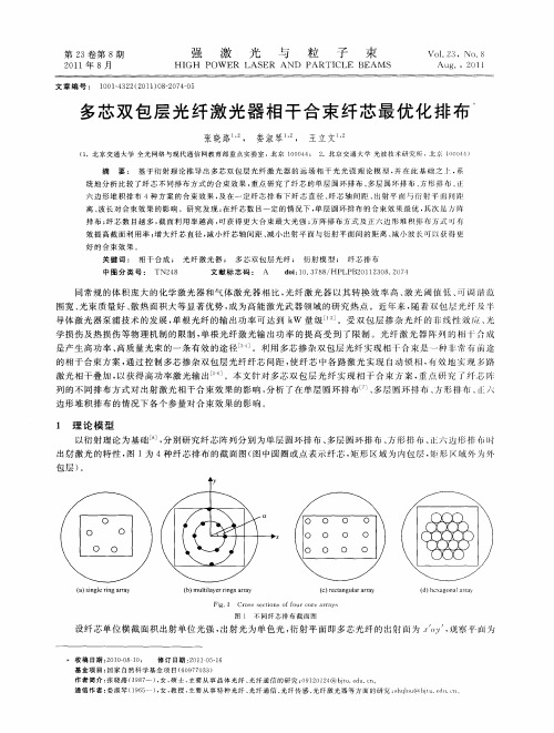
光纤激光器1、激光器基本结构激光器由三部分组成:泵浦源、增益介质、谐振腔。
图1 激光器基本结构示意图1.1 原子能级间受激吸收与受激辐射E 1E 2E 1E 2受激吸收E=E 1-E 2E1E 1E 2E 2E=E 1-E 2受激辐射E=E 1-E 2E=E 1-E 2图2 受激吸收与受激辐射示意图受激吸收为在能量为E 入射光子的作用下,处在低能级E 1的粒子吸收能量E 跃迁到高能级E 2的过程。
受激辐射为在入射的能量为E 的光子的作用下,处在高能级E 2的粒子受激发,跃迁到低能级E1,同时辐射出与入射光子E状态相同的光子的过程。
1.2激光产生过程如图1,激光器由泵浦源、增益介质、谐振腔组成。
增益介质为主要产生激光的工作物质。
由于粒子处在低能级比处在高能级稳定,因此通常情况下,物质粒子按照玻尔兹曼分布规律分布,即高能级粒子比低能级粒子少。
泵浦源为增益介质提供能量,使增益介质中的低能级粒子吸收能量,受激吸收,向高能级跃迁,使高能级处粒子数高于低能级粒子数,这种分布规律称为粒子数反转分布,使增益介质中积累了大量能量。
当有高能级粒子向低能级自发跃迁并释放出光子时,大量高能级粒子在初始光子作用下受激辐射,释放出大量状态相同,即波长相同、能量相同、方向相同、偏振态的光子。
这种在泵浦源与增益介质共同作用下使初始光子通过受激辐射效应放大而产生的光即为激光。
对特定波长激光全反射的输入镜与对该波长激光部分反射的输出镜构成光学谐振腔。
谐振腔主要有两方面作用:一是提供轴向光波的光学正反馈;二是控制激光震荡模式特性。
由于输出镜具有部分反射率,它可以使通过增益介质放大的光一部分通过透镜射出腔外,获得我们需要的特定波长的激光,另一部分反射回谐振腔,再由于输入镜对激光具有全反率,从而使轴向光波在谐振腔中往返传播,多次通过激活介质,在腔内形成稳定的自激振荡。
由于谐振腔镜只对特定波长的光镀全反射膜和部分反射膜,因此只有特定波长的光能产生自激震荡。
光纤激光器特点分类光纤激光器分类特点光纤激光器是指以光纤为基质掺入某些激活离子作做成工作物质,或者是利用光纤本身的非线性效应制作成的一类激光器.Nd2o3的光纤激光器是于1963年首先研制成功。
光纤激光器是一种新颖的有源光纤器件。
它的主要特点是:(1)光纤的芯径很细(10-15um),光纤内易形成的泵浦光功率密度,且单摸状态下激光与泵浦光可充分耦合,因此光纤激光器的能量转换效率高,激光阀值低;(2)工作物质可以做的很长,因此可获得很高的总增益;(3)腔镜可直接镀在光纤端面,或采用定向耦合起方式构成谐振腔,且由于光纤具有良好的柔绕性,而可以设计成相当紧凑的激光器构型;(4)光纤基质具有很宽的荧光光谱,并且还具有相当多的可调参数和选择性,因此,光纤激光器可以获得相当宽的调谐范围和好积的单色性。
光纤激光器的类型按照光纤材料的种类,光纤激光器可分成一下几种类型:一:晶体光纤激光器工作物质是激光晶体光纤,主要有红宝石单晶光纤激光器和nd3+:YAG单晶光纤激光器等;二:非线性光学型光纤激光器主要有受激喇曼散射光纤激光器和受激布里渊散射光纤激光器;三:稀土类掺杂光纤激光器光纤的基质材料是玻璃,向光纤中掺杂稀土类元素离子使之激活,而制成光纤激光器;四:塑料光纤激光器向塑料光纤芯部或包层内掺入激光染料而制成光纤激光器。
光纤激光器的迅速发展是基于近年来的光纤技术{拉晶体光纤技术、稀土掺杂光纤技术、单摸低损耗光纤和光纤耦合技术等}和大功率半导体激光技术的突破性进展。
特别是采用半导体激光二极管(ld)作为泵浦源,以其小体积和高效率为光纤激光器的实用化奠定了基础。
目前,光纤激光器已进入实用化阶段,已见有连续输出功率几千瓦,峰值功率几万千瓦。
半导体激光器半导体激光器又称激光二极管(LD)。
进入八十年代,人们吸收了半导体物理发展的最新成果,采用了量子阱(QW)和应变量子阱(SL-QW)等新颖性结构,引进了折射率调制Bragg发射器以及增强调制Bragg发射器最新技术,同时还发展了MBE、MOCVD及CBE等晶体生长技术新工艺,使得新的外延生长工艺能够精确地控制晶体生长,达到原子层厚度的精度,生长出优质量子阱以及应变量子阱材料。
光纤激光器是激光切割机中的核心部件,对激光切割机的切割效果有很大的影响。
在选择激光切割机时,需要考虑光纤激光器的模块集成方式是怎样的?光纤激光器的模块组成分为单模和多模两种,在切割应用中,聚焦光斑对切割出的质量有很大影响,单模激光器的纤芯比较细,光束质量优于多模,能量分布呈高斯分布,中间能量密度最高,三维图是一个尖圆的山峰状。
多模激光器的纤芯相比粗一些,光束质量相比单模要差一些,能量分布相比单模光斑平均一些,三维图像一个倒扣的杯子,从边缘陡峭程度来看,多模的比单模的陡峭很多。
同功率的1.5KW单模和1.5KW的多模激光器对比1mm薄板切割速度单模比多模高20%,视觉效果差不多,但从2mm开始,速度优势逐步下降,从3mm开始,无论是速度还是效果,高功率多模激光器速度和效果的优势就非常明显的体现出来,如下图:所以单模的优势在薄板,多模的优势在厚板,单模和多模并没有相互比较的价值,都是光纤激光器的一项配置,就好比一辆车,轿车适合公路,越野适合山地,但是轿车也能跑山地,越野也能跑公路,所以光纤激光器到底选多模还是单模要看实际终端客户的加工需求。
单模和多模,该如何选择呢?从功率级区分来看,1000W以内的激光器因为本身能量不高的原因,主要加工材料厚度偏向于薄板,因此1KW以内的激光器用单模配置比较符合市场实际情况,1KW以上功率的激光器要薄厚兼顾。
从整个加工行业来讲,加工质量的提升是一项刚性需求,是不能妥协的,因此很多高功率激光器选型不会考虑单模,必须保证加工质量为第一位!同时,单模的纤芯一般较细,意味着同样功率的激光在其中传输,单模纤芯的光能量承载更大,对材料是一项考验。
同时当切割高反材料时,高强度反射光和射出的激光叠加,如果光纤材料容忍度不足会非常容易“烧纤芯”,同时对纤芯材料寿命也是一项挑战!因此很多激光器厂商在高功率光纤激光器的配置上仍选用多模的配置!。
MCF(Multi-core Fiber)技术1.MCF介绍光纤通信技术经历了850nm波段,1310nm波段,1550nm波段应用,到密集波分复用技术及光放大器的出现,系统容量得到不断的提升。
随着5G的逐步广泛部署,全球向数字化经济和智能化社会发展,要求传输系统容量及单比特成本需要持续的优化。
系统容量及单比特传输成本继续优化的需求与现有海缆技术难以实现的矛盾越来越突出,迫切需要新的技术突破来支撑未来的持续演进。
而MCF技术为高速率、大容量、低成本的系统传输提供了可能。
MCF是多个纤芯在同一个包层区中的结构,可根据不同的纤芯种类、距离等参数设计不同芯数不同结构的多芯光纤,满足通信系统的需求。
可根据纤芯的相互接近程度不同,主要分成两种功能。
其一是纤芯间隔大,即低耦合的结构。
其二是使纤芯之间的距离靠近,能产生光波耦合作用。
利用此原理正在开发双纤芯的敏感器或光回路器件。
两种结构目前国内外均有相关研究。
低耦合MCF的纤芯间耦合较弱,多芯光纤的多个纤芯可作相对独立的信道,传输不同的光信息。
耦合系数一般小于0.01m-1,芯距>30μm,结构如下图1:图1 低耦合MCF截面图另一种多芯光纤是指纤芯之间的距离靠的很近,纤芯间能产生强光波耦合作用。
高耦合多芯光纤耦合系数一般大于0.1 m-1,芯距小于30μm,结构如下图2:图2 强耦合MCF截面图由于MCF的结构比普通的单模和多模光纤复杂,在制作过程中也会存在一定的不同。
制造流程图如图3:图3 MCF制作流程图与传统光纤相比,增加了玻璃棒的钻孔技术。
玻璃棒钻孔技术主要有四种: 研磨打孔法、电火花打孔法、超声波打孔法、激光打孔法。
激光打孔法适用于孔径小、速度快、精度高的石英玻璃加工;电火花打孔法的安全系数低;因而光纤预制棒一般打孔采用机械打孔和超声波打孔;但超声波打孔的效率较低、设备技术复杂、不利于批量生产。
机械打孔会在玻璃表面产生微裂纹,但可经过光纤制备工艺优化,微裂纹可愈合,不会产生较大的影响,企业多采用机械打孔制造多芯光纤预制棒。
Design of Rare Earth Doped Multicore Fiber Lasersand AmplifiersMichele Surico, Annalisa Di Tommaso, Pietro Bia, Luciano Mescia, Marco De Sario,Francesco PrudenzanoDEE- Dipartimento di Elettrotecnica ed Elettronica, Politecnico di Bari, Via Orabona, 4, 70125 Bari, Italye-mail: prudenzano@poliba.itABSTRACTA home-made computer code has been implemented to design high power ytterbium doped fiber lasers by following different techniques. The goal is to maximize the effective mode area by maintaining a good beam quality. As a preliminary simulation result, a novel aperiodic fiber lattice, very promising in order to construct high power and single mode lasers, has been identified. The laser obtained by employing the aforesaid aperiodic fiber has been compared, via simulation, with three other fiber sections, taken by literature but suitably optimized.Keywords: beam quality, innovative fibers, laser and amplifier modeling.1.INTRODUCTIONThe spreading of fiber lasers in a large number of fields is due to their high optical efficiencies and to their geometries allowing very good thermal properties. Nowadays, fiber lasers are definitively considered feasible sources in industrial, material science, medical, and military applications. Therefore, they are frequently employed for the construction of novel optical sources characterized by very high compactness and requiring simple cooling systems. As a consequence of the power up-scaling, recent fiber lasers are kilowatt class lasers in the continuous wave (CW) regime and they allow quasi-Gaussian beam distributions, whereas, in pulsed regime they are slightly less competitive. Fiber laser output beam quality, excellent even at high powers, permits the delivering of the optical beam with small diffraction values and, thus, these lasers result very useful for many applications. As a drawback, the appearance of nonlinear effects as Stimulated Brillouin or Raman scattering, four-wave mixing and photo-darkening, limits the maximum output power. These phenomena can induce both output power degradation and decreasing of spectral beam quality. The power threshold, at which nonlinear effects appear, can be significantly increased by exploiting large mode area (LMA) and double cladding fiber geometries, allowing cladding power pumping schemes. Novel optical fibers, characterized by large cores, have been investigated with the aim to prevent nonlinearity and to allow beam quality factor M2 close to the unit [1-5]. The large active core allows the enhancement of the pump absorption and the reduction of the power density, thus the active fiber length can be shortened. This further increases the threshold of the nonlinear effects. The main drawbacks are the decreasing of the beam quality and the increasing of bending sensitivity for single-mode (SM) fibers. Endlessly SM propagation, double cladding section, and LMA behavior can be obtained by employing microstructured optical fiber (MOF) lattices instead of the step index ones (SI F). Therefore, MOF technology, due to its versatility, can allow the right trade-off between the effective mode area and bending sensitivity requirements [6-11]. I n [4] the bending characteristics of solid-core LMA photonic bandgap fibers (PBG) with single-mode operation for high-power Yb-doped fiber lasers and amplifiers were investigated; the solid core PBGF having a 7-cell core achieved sufficient differential bending loss between the fundamental mode and the higher-order modes and a very large effective area limit.Multicore fibers (MCF) are an alternative way to enlarge the effective mode area. I n general, the MCF technology allows obtaining larger mode cross-section compared with that achievable via single core and single mode fibers [13-19]. Phase-locked multicore fiber lasers were demonstrated by Wrage et al. for the first time in [14]. I n those structures, the fiber cores provided slight evanescent coupling and phase locking was achieved through diffractive coupling using a Talbot cavity or a structured mirror.MCFs can be employed as amplifiers. As an example, in [12] a high power 19-core Yb-doped fiber amplifier in fundamental in-phase mode operation was demonstrated. A Q-switched single-core fiber laser with single transverse mode was used as seed. In [20] a ring-cavity laser included a multicore fiber amplifier and a single-mode fiber feedback for angular filtering of the beam and for selective seeding. I n [3] diffraction-limited fundamental mode amplification was demonstrated in Er-doped fibers with effective area of 1800 ȝm2. The amplifier utilized a Raman fiber laser as a pump and a LMA Er3+ fiber as an active medium. High peak powers and beam qualities were obtained with conventional fibers.In MCF lasers such as for the amplifiers, multiple rare earth doped cores are separated by undoped regions. The large mode area decreases the thermal stress and nonlinearity drawbacks arising from the high-power levels. However, quasi-Gaussian emission profiles can be obtained via MCF lasers only if the propagation of the different supermodes are taken into account and appropriate techniques of supermode selection or combining or filtering are adopted.In this paper, a home-made computer code is employed to investigate four different fiber lasers, optimized to obtain high brilliance and large mode area. The first two fiber lasers employ a Talbot cavity as a feedback mechanism for mode selection; they are based on i) a multimode (MM) 7 core SIF, and ii) a MM 19 core SIF. The other two fiber lasers are based on iii) a single mode (SM) 19 core SIF and iv) a completely novel SM 1 core aperiodic lattice and single material (silica with air holes) fiber. I n the following, the four optical fibers are named MM7CSIF, MM19CSIF, SM19CSIF, SM1CA.2.THEORYThe home-made computer code for simulation of ytterbium doped fiber lasers is implemented by considering the rate equations and the power propagation equations [21-23]. A two level scheme is employed to describe the ytterbium activated glass-system. The pump and the signal wavelengths are 976 nm and 1060 nm, respectively. The electrons in the 4F7/2ground level absorb the pump light and are promoted to level 4F5/2, this is the Ground State Absorption (GSA) phenomenon. The electrons can decay from metastable level 4F5/2to ground level, because of the signal stimulation. The stimulated emission enhances the signal power. Moreover, some of the electrons of the level 4F5/2 can spontaneously decay. The aforesaid mechanism is modeled for each supermode and for each doped cores. The propagation of all the supermodes is accurately taken into account. The supermode electromagnetic field profiles and the propagation constants are calculated by a commercial full vectorial finite element method FEM. The filling factor of the j-th core for the i-th mode is calculated as the ratio of power of the i-th mode inside the j-th core to the total power of the i-th mode [24-25]. All supermodes in MCFs compete with each other and give their contribute to the total population inversion.For the lasers based on: i) the MM 7 core SIF and ii) the MM 19 core SIF, both adopting the Talbot cavity feedback, the far field is calculated by using the Rayleigh-Sommerfeld diffraction equation via the FFT method. Among all supermodes, only the in-phase mode has a good far-field intensity profile; it is selected via the Talbot cavity between the fiber end and the feedback mirror. Self and cross coupling coefficients are calculated as in [24-25]. For SM19CSIF the SM 19 core SIF and SM1CA the novel SM single core aperiodic MOF the Talbot cavity is not required. The beam quality is evaluated via the theory reported in [26].3.RESULTSThe design of the chosen fiber sections has been performed via a large number of simulations in order to obtain similar effective mode areas A eff, and to optimize the laser performance. Figure 1 illustrates a sketch of the four fiber sections. For the SM1CA fiber, a quarter of the section is reported. It is a Thue-Morse transversal fiber section which includes eight air hole rings [27].a)b)and c)d)Figure 1. Laser fiber sections a) MM7CSIF, b) MM19CSIF, c) SM19CSIF, d) SM1CA.The distance between contiguous rings is not constant as in periodic PCF lattices, but it follows the aperiodic Thue-Morse sequence. More precisely, two ring distances, the first pitch ‘ΛA’ and second pitch‘ΛB’ are used. T N is the N order binary sequence of the two pitches ‘ΛA’ and ‘ΛB’. The T N+1 is generated from T N by replacing ‘ΛA’ with ‘ΛAΛB’ and replacing ‘ΛB’ with ‘ΛBΛA’. As examples, the first four terms of Thue-Morse sequence are T0={ΛA}, T1={ΛAΛB}, T2={ΛAΛBΛBΛA}, T3={ΛAΛBΛBΛAΛBΛAΛAΛB}. The T3lattice (ThMoT3) is consideredin the PCF design. In fact, the T1and T2lattices exhibit high confinement losses [27]. Table I reports the main parameters of the designed fibers. The emission and absorption cross sections of the ytterbium ions in silica glass and the losses are reported in [22-23]. Ytterbium ion concentration is 5×1025 ions/m3 . The distance between the mirror and the fiber end, Z M/2, of the Talbot cavity has been optimized to obtain the in-phase propagation. The fiber SM19CSIF and SM1CA fibers are designed to be single mode at the signal wavelength.Table I. Main laser and optical fiber parameters. Kind of fiber MM7CSIF MM19CSIF SM19CSIF SM1CANumber of cores 719191Cladding radius R cl 250 µm 250µm 250 µm 250 µm Core radius R co 5µm 4 µm 2 µm13 ȝm Air hole radius ###0.5 ȝm Centre to centre distance L co-co 17 µm 12 µm 5.5 µm#Pitch Λa ###20 ȝm Pitch Λb ###5ȝm Cladding refractive index n cl at Ȝs 1.4497 1.4497 1.4497 1.4497Core refractive index n co at Ȝs 1.4511 1.4527 1.4502 1.4497Air refractive index n A ###1Mirror reflectivity R 1 0.99 0.99 0.99 0.99 Mirror reflectivity R 2 0.04 0.04 0.04 0.04 Mirror - fiber end distance Z M /2 0.877 mm 1.155 mm ##As an example, Fig. 2 illustrates the variation of a) the self-coupling coefficient and b) the coupling from the in phase coefficient, versus the Talbot distance Z M , for the MM19CSIF. The curves exhibit the behavior reported in similar cases [25] and demonstrate that a selective feedback to obtain a good beam quality is feasible, because most of the power can be coupled to in-phase supermode.Talbot distance Z M[mm]C o u p l i n g f r o m i n p h a s e c o e f f i c i e n t ηi 1Talbot distance Z M [mm]S e l f c o u p l i n g c o e f f i c i e n t s ηi i a) b)Figure 2: a) the self-coupling coefficient and of b) the coupling from in phase coefficient,versus the Talbot distance Z M , for the MM19CSIF.Table II reports the main output laser characteristics, i.e. the effective mode area A eff , the beam quality M 2 and the slope efficiency ηs for the fiber length L = 10 m. The SM19CSI F laser exhibits the best beam quality M 2= 1.05, very close to that of SM1CA laser, M 2= 1.18 whereas the effective mode area A eff of SM1CA is larger than that of SM19CSIF.Table II.Output signal characteristics.FiberA eff [µm 2]M 2ηs MM7CS I F 830 2.58 0.75MM19CS I F 957 2.79 0.71SM19CS I F 703 1.05 0.70SM1CA 822 1.18 0.88 Figure 3 depicts the variation of the laser output versus the pump power (bidirectional) for the designed lasers with fiber length L =10 m. The SM1CA laser allows the best performance in terms of output power level to parity of pump power.Pump Power P p [W]L a s e r O u t p u t P o w e r P o u t [W ]Figure ser outputs versus the pump power, fiber length L=10 m.4.CONCLUSIONSFour kind of fiber lasers have been designed with the aim to obtain high power and high quality output beam. They have been compared via simulations. High performance lasers based on the fibers of the same kind of i), ii), iii), but differently optimized, have been reported in recent literature [1][18][20][24-25]. The aperiodic fiber laser iv) is novel and it seems very promising and competitive with respect to the state of the art. In fact, it exhibits the highest slope efficiency ηs = 0.88, a high effective mode area A eff = 822 µm 2 and a beam quality M 2 = 1.18 close to the theoretical one.ACKNOWLEDGEMENTSThe work has been developed within the COST ACTION MP0702: Towards Functional Sub-Wavelength Photonic Structures and within the PON01_01224 project.REFERENCES[1]M.M. Vogel, M. Abdou-Ahmed, A. Voss, T. Graf: Very-large-mode-area, single-mode multicore fiber,Optics Letters , vol. 34 (18), pp. 2876-2878, Sept. 2009.[2] F. Poli, E. Coscelli, T. T. Alkeskjold, D. Passaro, A. Cucinotta, L. Leick, J. Broeng, S. Selleri: Cut-offanalysis of 19-cell Yb-doped double-cladding rod-type photonic crystal fibers, Optics Express , vol. 19(10), pp. 9896-9907, 2011.[3]J. C. Jasapara, M. J. Andrejco, A. De Santolo, A. D. Yablon, Z. Vàrallyay, J. W. Nicholson, J. M. Fini,D. J. Di Giovanni, C. Headley,E. Monberg,F. V. Di Marcello: Diffraction-limited fundamental mode operation of core-pumped very-large-mode-area Er fiber amplifiers, IEEE Journal of Selected Topics in Quantum Electronics , vol. 15, pp. 3-11, 2009.[4]K. Saitoh, T. Murao, L. Rosa, M. Koshiba: Effective area limit of large-mode-area solid-core photonicbandgap fibers for fiber laser applications, Optical Fiber Technology, vol. 16, pp. 409-418, 2010.[5]Y.J. Song, M.L. Hu, C. L. Wang, Z. Tian, Q.R. Xing, L. Chai, C. Y. Wang: Environmentally stable, highpulse energy Yb-doped large-mode-area photonic crystal fiber laser operating in the soliton-like regime, IEEE Photonics Technology Letters , vol. 20, pp. 1088-1090, Jul. 2008.[6]J. C. Knight, T. A. Birks, P. S. J. Russell, D. M. Atkin: All-silica single-mode optical fiber with photoniccrystal cladding, Opt. Lett., vol. 21, pp. 1547-1549, Oct. 1996.[7]T. A. Birks, J. C. Knight, P. S. J. Russell: Endlessly single-mode photonic crystal fiber, Opt. Lett., vol. 22,pp. 961-963, Jul.1997.[8]J. C. Knight, T. A. Birks, R. F. Cregan, P. S. J. Russell, J.-P. De Sandro: Large mode area photonic crystalfibre, Electron. Lett., vol. 34, pp. 1347-1348, Jun. 1998.[9]K. Furusawa, A. N. Malinowski, J. H. Price, T. M. Monro, J. K. Sahu, J. Nilsson, D. J. Richardson:Cladding pumped Ytterbium-doped fiber laser with holey inner and outer cladding, Opt. Express , vol. 9, pp. 714-720, Dec. 2001.[10]P. Glas and D. Fisher: Cladding pumped large-mode-area Nd-doped holey fiber laser, Opt. Express, vol. 10,pp. 286-290, 2002.[11]W. J. Wadsworth, R. M. Percival, G. Bouwmans, J. C. Knight, P. S. J. Russell: High power air-cladphotonic crystal fibre laser, Opt. Express, vol. 11, pp. 48-53, Jan. 2003.[12]Y. Huo, P. K. Cheo, G. G. King: Fundamental mode operation of a 19-core phaselocked Yb-doped fiberamplifier, Optics Express, vol. 12, pp. 6230-6239, Dec. 2004.[13]J. R. Leger: Lateral mode control of an AlGaAs laser array in a Talbot cavity, Appl. Phys. Lett., vol. 55,pp. 334-336, 1989.[14]M. Wrage, P. Glas, D. Fisher, M. Leitner, D. V. Vysotsky, A. P. Napartovich: Phase locking in a multicorefiber laser by means of a Talbot resonator, Opt. Lett., vol. 25, pp. 1436-1438, 2000.[15][15] M. Wrage, P. Glas, D. Fisher, M. Leitner, D. V. Vysotsky, A. P. Napartovich: Combined phaselocking and beam shaping of a multicore fiber laser by structured mirrors, Opt. Lett., vol. 26, pp. 980-982, 2001.[16]P. K. Cheo, A. Liu, G. G. King: A high-brightness laser beam from a phase-locked multicore Yb-dopedfiber laser array, IEEE Photon. Technol. Lett., vol. 13, pp. 439-441, May 2001.[17]E. J. Bochove, P. K. Cheo, G. G. King: Self-organization in a multicore fiber laser array, Opt. Lett., vol. 28,pp. 1200-1203, 2003.[18]B.M. Shalaby, V. Kermene, D. Pagnoux, A. Desfarges-Berthelemot, A. Barthélémy , M. Abdou Ahmed,A. Voss, T. Graf: Quasi-Gaussian beam from a multicore fibre laser by phase locking of supermodes,Appl. Phys. B, vol. 97, pp. 599-605, May 2009.[19]L. Michaille, C. R. Bennett, D. M. Taylor, T. J. Shepherd: Multicore photonic crystal fiber lasers for highpower/energy applications, IEEE Journal of Selected Topics in Quantum Electronics, vol. 15, pp. 328-336, Mar./Apr. 2009.[20]B.M. Shalaby, V. Kermène, D. Pagnoux, A. Desfarges-Berthelemot, A. Barthélémy, A. Popp, M. AbdouAhmed, A. Voss, T. Graf: 19-cores Yb-fiber laser with mode selection for improved beam brightness, Appl.Phys. B, vol. 100, pp. 859-864, 2010.[21]F. Prudenzano, L. Mescia, T. Palmisano, M. Surico, M. De Sario, G. C. Righini: Optimization of pumpabsorption in MOF lasers via multi-long-period gratings: design strategies, Applied Optics, vol. 51,pp. 1410-1420, Mar. 2012.[22]A. D’Orazio, M. De Sario, L. Mescia, V. Petruzzelli, F. Prudenzano: Design of double-clad ytterbiumdoped microstructured fibre laser, Applied Surfaces Sciences, vol. 248, pp. 499-502, Jul. 2005.[23]G. Calò, A. D’orazio, M. De Sario, L. Mescia, V. Petruzzelli, F. Prudenzano: Design of cladding pumpedmicrostructured fiber amplifier, Optical Materials, vol. 28, pp.1243-1246, Aug. 2006.[24]Y. Huo, P.K. Cheo: Analysis of transverse mode competition and selection in multicore fiber lasers, J. Opt.Soc. Am. B, vol. 22 pp. 2345-2348, Nov. 2005.[25]C. Guan, L.Yuan, J. Shi: Supermode analysis of multicore photonic crystal fibers, Optics Communications,vol. 283, pp. 2686-2689, 2010.[26]A. Mafi, J. V. Moloney: Beam quality of photonic-crystal fibers, J. of Lightwave Technology, vol. 23,pp. 2267-2270, July 2005.[27]A. Di Tommaso, M. De Sario, L. Mescia, F. Prudenzano: Numerical analysis of aperiodic photonic crystalfiber structures for supercontinuum generation, Optical Engineering, vol. 51, pp. 035003-1-035003-6, Mar. 2012.。