中达电通MCS电源设备说明
- 格式:pptx
- 大小:6.89 MB
- 文档页数:68
中达电通MCS3000系列电源设备介绍MCS3000系列电源设备采用了现代化的设计理念,结构紧凑,体积小巧,便于安装和维护。
该系列电源采用了高效率的开关电源技术,具有高性能、高可靠性和高稳定性的特点。
其输出电压范围广泛,能够满足各种设备的功率需求。
MCS3000系列电源设备是一种可编程电源,具有高度灵活性和可定制性。
用户可以通过计算机或触摸屏界面轻松地设置电源的电压、电流、功率等参数。
该系列电源还具有多种保护功能,例如过载保护、短路保护、过压保护等,可以有效地保护设备和用户的安全。
MCS3000系列电源设备还配备了先进的监控和管理系统。
用户可以通过远程监控软件实时监测设备的工作状态,包括输入输出电压、电流、功率等。
该系列电源还支持远程控制和管理,用户可以通过网络远程控制和调整设备的参数。
MCS3000系列电源设备具有良好的稳定性和可靠性,能够在恶劣的工作环境下正常工作。
该系列电源设备采用了先进的散热设计和防尘防水技术,能够有效抵抗各种外界因素的影响。
此外,该系列电源还具有较长的工作寿命和低功耗,能够为用户节省能源和成本。
总的来说,中达电通MCS3000系列电源设备是一款功能齐全、性能稳定、操作简便的电源设备。
它可以广泛应用于各个领域,为各种设备提供高效稳定的电源供应。
无论是通信、工业控制、交通还是能源行业,MCS3000系列电源设备都能够满足不同应用场景的需求。

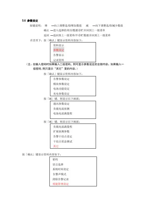
5.6参数设定
按键说明:增—向上调整选项/增加数值减—向下调整选项/减少数值确认—进入选择的项目/数据存贮并回到上一级菜单
返回—返回到上一级菜单/不存贮数据并回到上一级菜单
(注:在输入密码时如果输入二级密码,则可显示参数设定的全部内容;如果输入一级密码,则只显示“其它”里的内容。
)
按「确认」键显示资料内容如下:
按「减」键,则显示以下画面:
按「确认」键显示资料内容如下:
按「确认」键显示资料内容如下:
说明:
通信电源系统整流模块是按照N+1进行配置,因包含了蓄电池的充电电流,而对蓄电池的充电电流在绝大部分时间里是等于零的。
因此在实际使用中,整流模块的输出负载并不是很大,当整流模块工作在负载不是很大时,其工作的效率比较低,这种情况,电源系统可以采用节能模式管理功能以提高电源系统的工作效率。
即通过关闭一些整流模块,使工作中的整流模块工作在效率最佳点,从而达到提高电源系统的工作效率,减少用电量
以MCS3000为例
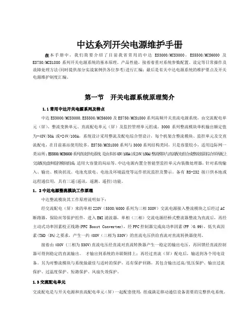
MCS3000系统整流模块的效率指标>90%,是指整流模块在满载时效率,而不同的带载段,模块的效率也不同。
负载越小,相对来说效率就越低,电网利用率也就越低。
根据负载情况,实时调节工作的模块数。
使模块负载保持在40%~80%之间。
下图为整流模块的负载效率曲线:
低载低效率。
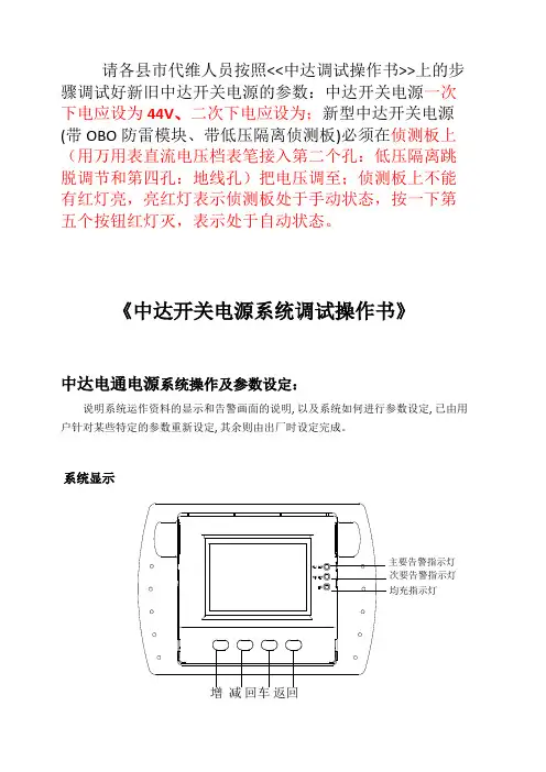
请各县市代维人员按照<<中达调试操作书>>上的步骤调试好新旧中达开关电源的参数:中达开关电源一次下电应设为44V、二次下电应设为;新型中达开关电源(带OBO防雷模块、带低压隔离侦测板)必须在侦测板上(用万用表直流电压档表笔接入第二个孔:低压隔离跳脱调节和第四孔:地线孔)把电压调至;侦测板上不能有红灯亮,亮红灯表示侦测板处于手动状态,按一下第五个按钮红灯灭,表示处于自动状态。
《中达开关电源系统调试操作书》中达电通电源系统操作及参数设定:说明系统运作资料的显示和告警画面的说明, 以及系统如何进行参数设定, 已由用户针对某些特定的参数重新设定, 其余则由出厂时设定完成。
增减回车返回主要告警指示灯次要告警指示灯均充指示灯1. 首页画面:监控单元(CSU )的资料显示,是液晶显示器(LCD)和三个发光二极管来执行。
红色为主要告警指示,黄色为次要告警指示,黄色为均充充电指示(见上的CSU 显示屏幕图示)。
液晶显示器首页显示画面的内容为:直流输出电压、直流输出电流、交流输入电压、系统状态。
在正常状况下系统异常告警资料并不显示,只有在供电系统发生异常时,才会有系统告警内容显示出来。
开机时首页画面显示:负载电流--供电系统输出总负载电流(取第二相) 状 态--显示系统的状态(浮充,均充)在首页下,按下列按键分别显示下列内容:增 —显示资料内容.(只能查看,不能设置或更改)减 —显示参数设定内容.(下面详细讲解)回车 —显示历史纪录内容和时间.(只能查看,不能设置或更改)返回 —显示告警内容.(只能查看,不能设置或更改)2. 系统操作参数设定画面在系统操作前,必须现进行模块ID 重置,操作步骤见,否则会导致系统模块均充灯闪烁不停。
增键 —向上调整选项/增加数值减键 —向下调整选项/减少数值回车键—进入选择的项目/数据存贮并回到上一级菜单返回键—返回到上一级菜单/不存贮数据并回到上一级菜单.1 告警参数设定在首页下,按减键显示参数设定内容如下(共有13项参数):监控单元CSU 显示屏幕高压停机设定按回车高压告警按回车键出现如下画面:此项不要求更改.(只需查看值为伏)低压告警按回车键出现如下画面:此项不要求更改.(只需查看值为44伏)交流高压告警按回车键出现如下画面:此项不要求更改.(只需查看值为290伏)交流低压告警按回车键出现如下画面:此项不要求更改.( 电池过温告警按回车此项不要求更改.(只需查看值为40)室温过温告警按回车此项不要求更改.(2(重点):.按回车键出现如下画面:或减键来改变手动或自动模式,画面如下:可以通过按增Array手动模式时,按设定Array注:可以通过按增或减键来改变限流值。
I N S T A L L A T I O N /O P E R A T I O NC653M-G (8/12)MCS SeriesMaster Power SupplyImportant Safeguards and WarningsObserve the following warnings before installing and using this product.1.Read these instructions.2.Keep these instructions.3.Heed all warnings.4.Follow all instructions.5.Do not use this apparatus near water.6.Clean only with dry cloth.7.Do not block any ventilation openings. Install in accordance with the manufacturer’s instructions.8.Do not install near any heat sources, such as radiators, heat registers, stoves, or other apparatus (including amplifiers) that produce heat.9.Only use attachments/accessories specified by the manufacturer.e only with the cart, stand, tripod, bracket, or table specified by the manufacturer or sold with the apparatus. When a cart is used, usecaution when moving the cart/apparatus combination to avoid injury from tip-over.11.Refer all servicing to qualified service personnel. Servicing is required when the apparatus has been damaged in any way, such as power-supply cord or plug is damaged, liquid has been spilled or objects have fallen into the apparatus, the apparatus has been exposed to rain ormoisture, the apparatus does not operate normally, or the apparatus has been dropped.12.Apparatus shall not be exposed to dripping or splashing, and no objects filled with liquids, such as vases, shall be placed on the apparatus.13.WARNING:To reduce the risk of fire or electric shock, do not expose this apparatus to rain or moisture.14.To reduce the risk of shock, do not perform any servicing other than that contained in the operating instructions unless you are qualified todo so.15.WARNING:Risk of fire; do not interconnect outputs.16.An ALL-POLE MAINS SWITCH with a contact separation of at least 3 mm in each pole shall be incorporated in the electrical installation ofthe building.17.The installation method and materials should be capable of supporting four times the weight of the unit.18.Only use replacement parts Pelco recommends.19.After replacing/repairing this unit’s electrical components, conduct a resistance measurement between line and exposed parts to verify theexposed parts have not been connected to line circuitry.20. A readily accessible disconnect device shall be incorporated in the building installation wiring.The product and/or manual may bear the following marks:This symbol indicates that dangerous voltage constituting a risk of electric shock ispresent within this unit.in the literature accompanying this unit.Please thoroughly familiarize yourself with the information in this manual prior to installation and operation.CAUTION:RISK OF ELECTRIC SHOCK.DO NOT OPEN.DescriptionThe MCS Series consists of multi-output 24 VAC indoor power supplies. These power supplies provide output for 4, 8, or 16 cameras from a single source and come in 2, 5, 10, and 20 A capacities. To compensate for voltage losses over long wire runs, 28 VAC outputs are also available on most models. The power supplies allow for 120 or 240 VAC line input. Higher capacity models can handle pan and tilt and receiver operation in addition to the camera when they are used with integrated systems such as the Spectra ® dome and Esprit ® Integrated Positioning System.Each output on the MCS “S” and “SB” (switched) Series models features its own LED power indicator and three-position switch (up = 24 VAC, center = off, down = 28 VAC). The switch lets you individually turn off each output or quickly select between 24 and 28 VAC without reconnecting wires.All MCS Series models are available with either glass fuses or self-resetting circuit breakers (poly switches). The following bullets explain the advantages and disadvantages of each type:•Glass fuses provide more protection than circuit breakers because they act faster and are more precise. However, they are designed for one-time use and must be replaced when they blow.•Circuit breakers reset themselves when the fault is corrected, which eliminates the need to replace fuses. However, they react more slowly, are affected by temperature, and are not nearly as accurate; the amount of current required to trip one can vary as much as 100 percent.Since circuit breaker models do not require fuses and automatically reset themselves after the fault is corrected, the breakers are not accessible.MODELS*The output of a channel cannot exceed this rating (1.5 A), and the total of all outputs cannot exceed the overall rating of the power supply (2 A). For example, if one channel's output is 1A, then you can have one more channel output of 1A or two more channel outputs of 0.5 A.Model Number O u t p u t sS u p p l y C u r r e n t (A m p s )M a x C u r r e n t P e r C h a n e l (A m p s )I n p u t V o l t a g e (V A C )O u t p u t V o l t a g e (V A C )R e q u i r e d I n p u t C u r r e n t (A m p s )F u s e sC i r c u i t B r e a k e r sS u r g e P r o t e c t i o n C l a s s 2 O u t p u t sO n /O f f S w i t c h P o w e r L E D MCS4-2*42 1.5120/240240.6/0.3XX X X MCS4-2B*42 1.5120/240240.6/0.3X X X X X MCS8-5853120/24024,28 1.4/0.7XX X X MCS8-5B 853120/24024,28 1.4/0.7X X X X X MCS16-1016103120/24024,28 2.7/1.35XX X X MCS16-10B 16103120/24024,28 2.7/1.35X X X X X MCS16-10S 16103120/24024,28 2.7/1.35XX 1616MCS16-10SB 16103120/24024,28 2.7/1.35X X X 1616MCS16-2016203120/24024,28 5.0/2.5XX X X MCS16-20B 16203120/24024,28 5.0/2.5X X X X X MCS16-20S 16203120/24024,28 5.0/2.5XX 1616MCS16-20SB16203120/24024,285.0/2.5XXX1616APPLICATION EXAMPLESTable A contains examples of products and the number of units that can be powered by each power supply, and is based on the VA rating of each product.InstallationTo install an MCS Series Power Supply, perform the following steps:1.Punch out the necessary knockouts. (Two knockout holes are provided on the bottom for either 1.27 cm (1/2-inch) or 1.91 cm (3/4-inch) conduit fittings for the incoming (main) power. Six knockout holes are provided on the top for either 1.27 cm (1/2-inch) or 1.91 cm (3/4-inch) conduit fittings for the output (24-28V) power.2.Open the lid on the unit by removing the 8-32 Phillips screw.3.Install conduit fittings (not provided).4.Determine the location of the unit.5.Refer to Figure 1. Drill holes in the mounting surface (two of the mounting holes are inside the unit). Use the unit as a template.6.Attach the unit securely with four fasteners (not supplied) of the appropriate length. You can use fasteners up to 0.80 cm (5/16-inch) in diameter.Figure 1. Power Supply MountingTable A. Product CapacityProductPower Supply ModelMCS4-2/MCS4-2BMCS8-5/MCS8-5BMCS16-10/MCS16-10B/MCS16-10S/MCS16-10SBMCS16-20/MCS16-20B/MCS16-20S/MCS16-20SBCCD Camera (12 VA maximum)481616DF5/DF5S with camera (3 VA)481616DF5/PDF8 (12 VA maximum)481616Indoor Spectra (30 VA)14816Esprit without wiper or IOC/IOP (50 VA)248INPUT CONNECTIONS1.Verify that the on/off switch inside the box is OFF. On MCS “S” and “SB” (switched) models, verify that the switch for each output is at the center (OFF) position.2.Refer to Figure 2 or3. Remove the high-voltage compartment panel inside the box. Set the input voltage selector switch inside the compartment to the appropriate line voltage. The switch is set at the factory for 120 VAC line voltage.3.If you are using 120 VAC line voltage, proceed to step4. If you have a fuse model and are using 240 VAC line voltage, remove the 120 VAC fuse from the fuse holder directly above the power switch and install the appropriate fuse (refer to Table B). Find the fuse in the bag located inside the high-voltage compartment. (Extra fuses are supplied for spares.)4.Attach the 120/240 input wires to the flying leads in the compartment with the supplied clamp connectors. Connect the black wire to the AC line lead. Connect the white wire to the AC neutral lead.5.Attach the input ground wire to the stud inside the compartment with the supplied washer and nut.6.Replace the access panel.*Model is not equipped with a primary input fuse; transformer is protected with thermal breaker.**MCS4-2B uses a fuse for the high-voltage line input and provides breakers for the low-voltage output channels.OUTPUT CONNECTIONSPerform the following steps to attach 24 VAC devices to the MCS Series Power Supply:1.Refer to Tables C and D in this manual or the wiring table on the unit’s lid to determine the output wiring needed for your devices.2.Refer to Figure 2 (or Figure 3 for “S” and “SB” models) for the proper connector strip connections, and do one of the following:•Regular MCS models: For each device, attach one output wire to the COM (common) terminal. Attach the second wire to the appropriate 24 V or 28 V terminal.•“S” and “SB” (switched) models: For each device, attach one output wire to the COM (common) terminal and the second wire tothe 24/28 V terminal.3.When you finish the wiring connections, double-check the installation for safety purposes.4.Power up the unit with the ON/OFF switch. On MCS “S” and “SB” (switched) models, move the switch to the appropriate output voltage position (up = 24 VAC, down = 28 VAC) to provide power.e a voltmeter to verify that used outputs are at appropriate voltage levels.6.Close the lid and secure it using the 8-32 Phillips screw.Pelco shall not be liable for any damages resulting from incorrect wiring or improper loading of an MCS Series Power Supply.Units are equipped for 120 VAC line voltage at the factory. If you are using 240 VAC, you must change the main fuse (fuse blow (fuse models) or the thermal breaker will open (breaker models).Table B. Fuse Determination TableLine Voltage M C S 4-2M C S 4-2B **M C S 8-5M C S 8-5B M C S 16-10/M C S 16-10SM C S 16-10B /M C S 16-10S BM C S 16-20/M C S 16-20S M C S 16-20B /M C S 16-20S B 120 VAC 1.5 A 1.5 A 1.6 A ** 3 A ** 5 A **240 VAC0.5 A0.5 A1 A**1.6 A**3 A**Under light load conditions and high power line input voltage from the utility company, output voltage from the power supply duce variable loads (due to heaters, blowers, and pan and tilt motion) and during minimum requirements may create a light load condition, causing excessive voltage. Therefore, Pelco recommends using a 28 VAC tap only when the supplied wire size for the given load causes an unacceptable output voltage on the 24 VAC tap. Refer to Table D to determine acceptable situations for the 28 VAC tap.The following table shows the recommended maximum distances (transformer to load) and are calculated with a 10-percent voltage drop. (Ten percent is generally the maximum allowable voltage drop for AC-powered devices.) Distances are calculated in meters; values in parentheses are feet.You can use Table D as a guide to determine the necessary wire gauge (AWG) for various cable distances that provide 24 VAC power. Or use it in a reverse fashion to determine the maximum allowable cable distance for a particular wire gauge. Table D applies when using two-conductor copper wire, with characteristics similar to West Penn 221-227 unshielded cable. Calculations are based on a 10-percent voltage drop (generally the maximum allowable drop for AC-powered devices).The minimum acceptable voltage is calculated as follows:24.0 VAC –02.4 (10%)21.6 (Minimum Acceptable Voltage)The minimum acceptable voltage used to create Table D was 21.6 V. Therefore, the 24-V output has an acceptable range from 24 V down to 21.6V; the 28-V output’s acceptable range is from 28 V down to 21.6 V.Table C. Recommended Wiring DistancesInput Voltage Total VA ConsumedWire Gauge20181624 VAC1086(283)137(451)218(716)2042(141)68(225)109(358)3028(94)45(150)72(238)5017(56)17(90)43(143)28 VAC1086(283)137(451)218(716)2058(193)93(307)148(487)3039(128)62(204)99(325)5023(77)37(122)59(195)Figure 3. MCS “S” and “SB” Unit WiringConnector DiagramFigure 2. MCS Unit Wiring Connector DiagramMaintenanceThere are no user-serviceable parts except for the fuses. If the transformer in the unit does not work properly, contact the factory for return information. Refer to the Warranty and Return Information section on page 11.Clean the outer surface of the power supply with a nonabrasive cleaning cloth and anti-static cleaner. Do not use kerosene or similar substances that may damage the surface.Table D. Required Wire Gauge Table (AWG)Equipment Loads (VA)WIRE DIST (feet)C CD C a m e r aP /T 480 P a n /T i l tI n d o o r S p e c t r aP T 570P a n /T i l tE s p r i t P a n /T i l tI n d o o r X L SC X 9000R x r ’sO u t d o o r S p e c t r a 10 VA 20 VA 30 VA 40 VA 50 VA 60 VA 70 VA 80 VA 90 VA 100 VA 200 VA 100012-1412*********16-1812-1412-1412*******90012-141212********16-1814-1612-141212******80012-141212********16-1814-1612-14121212*****70012-16121212*******18-2014-1612-1412-141212*****60012-16121212*******18-2014-1814-1612-1412-14121212***50012-1612-14121212******18-2016-1814-1612-1412-1412-14121212**40012-1812-141212121212****20-2216-1814-1814-1612-1412-1412-14121212*30012-1812-1612-14121212121212**20-2218-2016-1814-1814-1614-1612-1412-1412-1412-14*20012-2012-1812-1612-1412-141212121212*2220-2218-2016-1816-1814-1614-1614-1614-1612-1412-1410012-2212-2012-1812-1812-1612-1612-1612-1412-1412-1412N/A 2220-2220-2218-2018-2018-2016-1816-1812-1412-14XX-XX Allowable Wire Gauge (AWG) Using 24-V Tap XX-XXAllowable Wire Gauge (AWG) Using 28-V Tap*Distance and Load Not Recommended For Any Wire Size Between 12-22 (AWG)SpecificationsMECHANICALCable Entry Knockouts for either 1.27 cm (1/2-inch) or 1.91 cm (3/4-inch) conduit Fuse SizeAll Fuse Models All fuses are 5 x 20 mmELECTRICALInput VoltageAll Models120 or 240 VAC, 50/60 HzOutput VoltageMCS4-224 VACAll Other Models24/28 VACRequired Input Current Refer to Models on page4Output Fuse RatingsMCS4-2 1.5, 1.0, 0.5 AMCS8-5 3 AMCS16-10/16-10S 3 AMCS16-20/16-20S 3 AOutput Circuit Breaker RatingsMCS4-2B0.9 AMCS8-5B 3 AMCS16-10B/16-10SB 3 AMCS16-20B/16-20SB 3 AInput Connectors Clamp connectorOutput Connectors Screw-type barrier stripsInput Wire Size12-16 gauge solid wireOutput Wire Size12-22 gauge solid or stranded wireRecommended Wiring Distances Refer to Table CGENERALConstruction SteelFinish Black polyester powder coatEnvironment IndoorOperating Temperature0° to 49°C (32° to 120°F)Dimensions11.10 x 27.58 x 40.97 cm(4.37" D x 10.86" W x 16.13" H)Approximate Unit Weight9.87 cm (21.75 lb)RATINGSMeets NEMA Type 1 standardsPRODUCT WARRANTY AND RETURN INFORMATION WARRANTYPelco will repair or replace, without charge, any merchandise proved defective in material or workmanship for a period of one year after the date of shipment. Exceptions to this warranty are as noted below:•Five years:–Fiber optic products–Unshielded Twisted Pair (UTP) transmission products–CC3701H-2, CC3701H-2X, CC3751H-2, CC3651H-2X, MC3651H-2, and MC3651H-2X camera models•Three years:–FD Series and BU Series analog camera models–Fixed network cameras and network dome cameras with Sarix® technology –Sarix thermal imaging products (TI and ESTI Series)–Fixed analog camera models (C20 Series, CCC1390H Series, C10DN Series, and C10CH Series)–EH1500 Series enclosures–Spectra®IV products (including Spectra IV IP)–Spectra HD dome products–Camclosure® IS Series integrated camera systems–DX Series video recorders (except DX9000 Series which is covered for a period of one year), DVR5100 Series digital video recorders, Digital Sentry®Series hardware products, DVX Series digital video recorders, and NVR300 Series network video recorders–Endura®Series distributed network-based video products–Genex® Series products (multiplexers, server, and keyboard)–PMCL200/300/400 Series LCD monitors–PMCL5xxF Series and PMCL5xxNB Series LCD monitors•Two years:–Standard varifocal, fixed focal, and motorized zoom lenses–DF5/DF8 Series fixed dome products–Legacy® Series integrated positioning systems–Spectra III™, Spectra Mini, Spectra Mini IP, Esprit®, ExSite®, ExSite IP, and PS20 scanners, including when used in continuous motion applications –Esprit Ti and TI2500 Series thermal imaging products–Esprit and WW5700 Series window wiper (excluding wiper blades)–CM6700/CM6800/CM9700 Series matrix–Digital Light Processing (DLP®) displays (except lamp and color wheel). The lamp and color wheel will be covered for a period of 90 days. The air filter is not covered under warranty.•Six months:–All pan and tilts, scanners, or preset lenses used in continuous motion applications (preset scan, tour, and auto scan modes)Pelco will warrant all replacement parts and repairs for 90 days from the date of Pelco shipment. All goods requiring warranty repair shall be sent freight prepaid to a Pelco designated location. Repairs made necessary by reason of misuse, alteration, normal wear, or accident are not covered under this warranty.Pelco assumes no risk and shall be subject to no liability for damages or loss resulting from the specific use or application made of the Products. Pelco’s liability for any claim, whether based on breach of contract, negligence, infringement of any rights of any party or product liability, relating to the Products shall not exceed the price paid by the Dealer to Pelco for such Products. In no event will Pelco be liable for any special, incidental, or consequential damages (including loss of use, loss of profit, and claims of third parties) however caused, whether by the negligence of Pelco or otherwise.The above warranty provides the Dealer with specific legal rights. The Dealer may also have additional rights, which are subject to variation from state to state.If a warranty repair is required, the Dealer must contact Pelco at (800) 289-9100 or (559) 292-1981 to obtain a Repair Authorization number (RA), and provide the following information:1. Model and serial number2. Date of shipment, P.O. number, sales order number, or Pelco invoice number3. Details of the defect or problemIf there is a dispute regarding the warranty of a product that does not fall under the warranty conditions stated above, please include a written explanation with the product when returned.Method of return shipment shall be the same or equal to the method by which the item was received by Pelco.RETURNSTo expedite parts returned for repair or credit, please call Pelco at (800) 289-9100 or (559) 292-1981 to obtain an authorization number (CA number if returned for credit, and RA number if returned for repair) and designated return location.All merchandise returned for credit may be subject to a 20 percent restocking and refurbishing charge.Goods returned for repair or credit should be clearly identified with the assigned CA or RA number and freight should be prepaid.The materials used in the manufacture of this document and its components are compliant to the requirements of Directive 2002/95/EC.This equipment contains electrical or electronic components that must be recycled properly to comply with Directive 2002/96/EC of the European Unionregarding the disposal of waste electrical and electronic equipment (WEEE). Contact your local dealer for procedures for recycling this equipment.Revised 1-12-12REVISION HISTORYManual #Date CommentsC653M3/99Original version.5/99Revisions made because fuses are no longer in a bag but in holders. Added weight.C653M-A8/99Added material on the four “S” and “SB” (switched) power supply models.C653M-B6/00Changed fuse installation information. Updated compliance information.C653M-C8/02Added CE certification. Revised Important Safeguards and Warnings.C653M-D9/03Revised Important Safeguards and Warning to advice against interconnecting outputs. Revised table of models to show which one have Class 2 outputs.C653M-E3/07Added operating temperature. Revised manual format.C653M-F6/07On page 4, changed the maximum current per channel from 1 A to 1.5 A for the MCS4-2 and MCS4-2B in the chart, and added a comment below the chart. On page9, changed the output fuse ratings for the MCS4-2, and added a comment at the bottom of the page.C653M-G8/12Revised for UL re-certificaton.Pelco, the Pelco logo, and other trademarks associated with Pelco products referred to in this publication are trademarks of Pelco, Inc. or its affiliates. © Copyright 2012, Pelco, Inc. ONVIF and the ONVIF logo are trademarks of ONVIF Inc. All other product names and services are the property of their respective companies.All rights reserved. Product specifications and availability are subject to change without notice.Pelco by Schneider Electric 3500 Pelco Way Clovis, California 93612-5699 United States USA & Canada Tel (800) 289-9100 Fax (800) 289-9150International Tel +1 (559) 292-1981 Fax +1 (559) 348-1120。
MCS3000D 系统效能管理设定
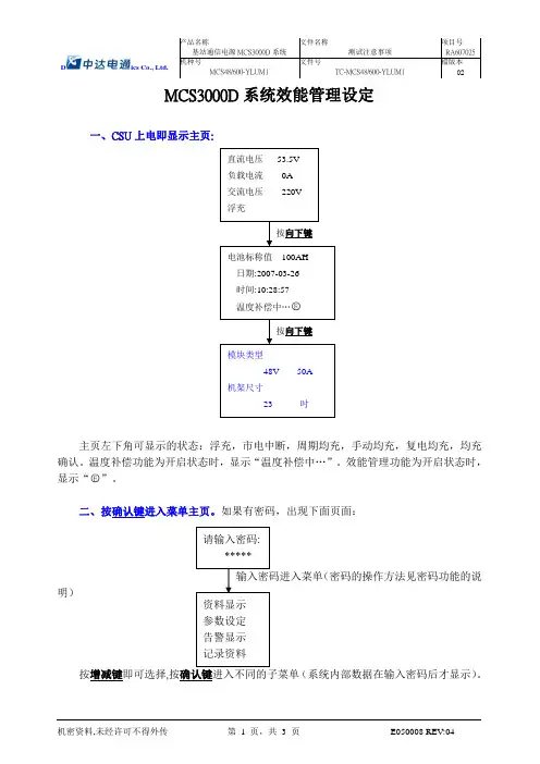
一、CSU 上电即显示主页:
主页左下角可显示的状态:浮充,市电中断,周期均充,手动均充,复电均充,均充
确认。
温度补偿功能为开启状态时,显示“温度补偿中…”。
效能管理功能为开启状态时,
显示“○E ”。
二、按确认键进入菜单主页。
如果有密码,出现下面页面: (密码的操作方法见密码功能的说
明)
按增减键即可选择,按确认键进入不同的子菜单(系统内部数据在输入密码后才显示)。
三、选参数设定菜单
注:在输入密码时如果输入二级密码,则可显示参数设定的全部内容如果输入一级密码,则只显示“其它”里的内容。
四、选其它子菜单
从其它子菜单中选效能管理设定,按确认键后即可进行此功能打开或关闭设定。
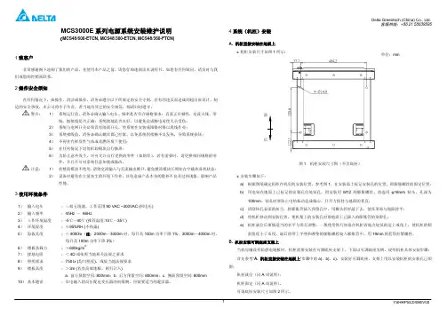
中达系列开关电源维护手册在本手册中,我们简要介绍了目前我省常用的中达ES3000/MCS3000,ES5500/MCS6000及ES750/MCS1800系列开关电源系统的基本原理、产品性能,接着着重对系统参数配置、设定等日常操作及故障处理方法(同时提供部分实战案例供各位参考)进行汇编;最后是有关中达电源系统的维护要点及开关电源维护制度汇编。
第一节开关电源系统原理简介1.1常用中达开关电源系列及特点中达ES3000/MCS3000,ES5500/MCS6000及ES750/MCS1800系列高频开关直流电源系统,由交流配电单元(屏)、整流变换单元、直流配电单元(屏)及监控管理单元组成。
3000系列整流模块单机输出额定值为-48V/50A或+24V/100A,系统设计采用整流及配电综合型设计,每个机架含整流模块、监控单元及交直流配电,在目前基站使用较多。
ES750/MCS1800系列与3000系列结构类同,只是容量较小,适用边际网一类站所;ES5500/MCS6000系列直流供电系统,是由多部48V/100A(或24V/150A)整流模块与直流配电组合成整流低阻综合屏再配上交流配电盘和监控模块组成;适用大容量的局站等。
中达电源内置全智能型监控单元内装微处理器,针对系统输入、输出、模块状况、电池充放电、电池及环境温度等运作状况监控及警示。
备有RS-232接口供本地或远程通信用,具有三遥(遥讯、遥测、遥控)功能。
1.2中达电源整流模块工作原理中达整流模块其工作原理说明如下:经交流配电(屏)来的单相220V(5500/6000系列为三相380V)交流电源接入整流模块之后经过AC 断路器,保险丝等保护组件,进入EMI滤波器,单相(三相)交流电源经桥式整流器整流为直流后,再经主动式功率因素校正线路(PFC Boost Converter),经PFC控制器完成高功率因素(PF >0.99),低失真因素(THD <5%)之要求,产生一约400V(三相为530V)的直流电压供给直流对直流转换器使用。

中达开关电源MCS3000H操作及参数设定一、概述此章是说明系统运作资料的显示和告警画面的说明, 以及系统如何进行操作参数设定,指导用户针对某些特定的参数重新设定, 其余则由出厂时设定完成。
二、系统显示系统开机显示产品系列和监控软件的版本,如下所示:中达电通MCS3000H版本:V1.0.00监控模块提供4行16个字符格式数字式的液晶LCD显示器,通常显示系统输出直流电压、负载总电流和系统状态(浮充或均充),这就是默认的主页(如下图所示)。
200 A 54.0 V浮充-48V系统注:无告警的情况下,如果当前画面不在主页,没有按键操作超过40秒显示器自动转回主页;有告警时,主页与告警提示页交替显示。
三、前面板按钮除了在监控模块或菜单主页中,有下列5个菜单按钮中包括了系统中绝大多数的参数,通过这些菜单可直接进入相关联的项目:a)b)中;c),储存了最近发生的100条告警信息(包括告警数据和时间)。
d),包括所有系统参数菜单,同时针对每一项设定利用加和减键来修改设定值。
e)结束后再按一次回车键确认。
四、状态指示灯除了液晶显示器中的菜单内容外,另外有3个系统状态指示灯如下:系统运行正常 绿色指示灯告警/均充! 黄色指示灯整流模块关机 红色指示灯如果这3个指示灯都关闭,则表示系统关机,可能的原因如下所列:监控模块内部故障黄色告警指示灯代表任何告警状态的发生,既包括系统也包括模块的有关告警,当告警出现时,按回车键查看告警内容。
红色告警灯亮表示有一个或多个整流模块关机。
监控模块中所有可能的告警列在下面的表格中:五、操作5.3节所示)。
数而不需一个一个的向下翻页。
参考后续的5.5.2,5.5.3,5.5.4节的描述。
任何情况下,要返回监控模块主页,只要再按当前的菜单按钮一次即可。
例如:如果当先按1、系统菜单1) 环境温度值(摄氏度℃)2) 单相交流电压值单相AC电压218V3) 单相交流电流值单相AC电流0A4) 环境温度过高告警值(摄氏度℃)环境温度告警值39C5) 输出电压过高告警值高压告警值57.5V6) 输出电压过低告警值低压告警值46.5V7) 模块限流之最小值。
中达MCS-3000高频开关电源系统一、电源柜组成高频开关电源主要有交流配电单元、直流配电单元、CSU 监控单元、SMR 整流模块单元等组成。
如下图所示:二、监控单元监控单元的作用是监控系统输入输出,整流模块状态、电池及环境温度、充放电控制与异常状况的告警与指示。
备有RS-232接口,具有遥讯、遥测、遥控功能,符合无人值守CSU监控单元PDU直流配电单元SMR Shelf 架每层SHELF 能放 置6 SMRSMR : ESR 48/50 或 ESR 24/100与集中监控的需要。
外接PC机采用中文窗口环境操作,可配合打印机提供系统文字信息,亦具有传呼机告警功能,能将主要告警通知用户,使用户随时获得系统最新信息。
监控单元与整流模块间以信号线联机。
它收集由整流模块传来的告警信号及电流值。
并可对整流模块下达停机、浮充/均充控制及浮充电压温度补偿的电压修正指令。
监控单元分老型号和新型号,功能其实是一样,只不过操作按键功能不同而已。
下图出现告警时,可以通过清除侦测板告警或清除通信不良,看告警是否能够恢复,如果不能恢复,再根据告警内容去解决。
对于有告警但没有没有告警内容或按键不起作用、面板显示不正确等故障,可以通过复位CSU 来解决。
三、整流模块整流模块面板指示灯 (1)LOAD (负载电流) : 5段绿色LED 显示,各代表负载容量(2)AC ON (交流市电) : 绿色LED 显示表示模块工作,不亮表示不工作 (3) CL ( 限流) : 黄色LED 显示表示有限流,不亮表示没有 (4)FF (风扇故障): 红色LED 显示表示风扇故障,需要更换风扇(5)RF (整流模块故障) : 红色LED 显示表示整流模块故障,需要更换 (6)EQU (均充充电): 黄色LED 显示有均充或整流模块没有得到确认衡量一个整流模块的好坏还有一个重要参数----均流不平衡度 : ≤ ± 5%四、侦测板侦测板的功能是如下:1. 收集侦测负载熔丝熔断的信号,送给CSU 处理。