电磁阀样本
- 格式:pdf
- 大小:1.32 MB
- 文档页数:13
华德电磁阀样本华德电磁阀是一种常见的控制阀,它利用电磁力来控制液体或气体的流动。
本文将详细介绍华德电磁阀的结构、工作原理以及应用领域。
一、华德电磁阀的结构华德电磁阀主要由电磁铁、阀体、阀芯、弹簧和密封件等部分组成。
其中,电磁铁是控制阀的重要组成部分,通过电流的通断来产生电磁力,控制阀芯的开闭。
阀体是安装阀芯的容器,通常由铜、铸铁或不锈钢制成。
阀芯是控制介质流动的关键部分,通常由铜或不锈钢制成。
弹簧用于控制阀芯的位置,保证阀芯在电磁力作用下能够恢复到关闭状态。
密封件则起到密封作用,防止介质泄漏。
二、华德电磁阀的工作原理华德电磁阀的工作原理基于电磁感应的原理。
当通电时,电磁铁会产生磁场,通过磁场作用于阀芯,使其与阀座分离,从而打开阀门,介质开始流动。
当断电时,电磁铁不再产生磁场,阀芯受到弹簧的作用,恢复到关闭状态,阀门关闭,介质停止流动。
三、华德电磁阀的应用领域华德电磁阀广泛应用于工业自动化控制系统中,常见的应用领域包括液压系统、气动系统、给排水系统等。
在液压系统中,华德电磁阀可以控制液压油的流量和压力,实现液压系统的稳定运行。
在气动系统中,华德电磁阀可以控制气体的流量和压力,实现气动设备的控制。
在给排水系统中,华德电磁阀可以控制水的流量和方向,实现给排水管道的控制。
华德电磁阀的优点是结构简单、可靠性高、响应速度快、使用寿命长。
它具有良好的密封性能,可以防止介质泄漏,确保系统的安全运行。
同时,华德电磁阀具有较高的自动化程度,可以与控制系统实现无缝连接,实现自动化控制。
总结起来,华德电磁阀是一种常见的控制阀,通过电磁力来控制介质的流动。
其结构简单、工作可靠,广泛应用于工业自动化控制系统中。
华德电磁阀在液压系统、气动系统、给排水系统等领域具有重要作用,能够实现流量、压力和方向的控制。
通过了解华德电磁阀的结构和工作原理,我们可以更好地理解其在实际应用中的价值和作用。
华德电磁阀样本
(实用版)
目录
1.华德电磁阀样本概述
2.华德电磁阀样本的详细信息
3.华德电磁阀样本的应用范围和优势
正文
一、华德电磁阀样本概述
华德电磁阀样本是由华德公司提供的一种高品质电磁阀产品,主要用于流体的自动化控制。
本文将详细介绍华德电磁阀样本的详细信息,包括其结构、功能和应用范围等方面的内容。
二、华德电磁阀样本的详细信息
1.结构特点
华德电磁阀样本采用模块化设计,具有结构简单、体积小、重量轻、安装方便等特点。
其主要由电磁线圈、铁芯、阀体、阀座、密封件等部件组成,可根据不同工作环境和介质要求选择合适的材料。
2.功能特点
华德电磁阀样本具有以下功能特点:
(1)高精度:电磁阀的控制精度高,可实现精确的流量和压力控制。
(2)快速响应:电磁阀的响应速度快,能够实现快速开启和关闭。
(3)可靠稳定:电磁阀具有优良的抗干扰性能,可确保在复杂工况下的稳定运行。
(4)低能耗:电磁阀的能耗低,可节省能源,降低运行成本。
三、华德电磁阀样本的应用范围和优势
华德电磁阀样本广泛应用于工业自动化、化工、石油、冶金、电力、船舶等领域。
其主要优势如下:
1.广泛的应用范围:由于华德电磁阀样本具有较高的适应性和可靠性,可应用于各种工况和介质,满足不同场合的需求。
2.高效的自动化控制:华德电磁阀样本可实现远程控制和集中控制,提高生产效率和自动化水平。
3.良好的节能效果:华德电磁阀样本的低能耗特性能够降低运行成本,实现绿色生产。
4.减少人工操作:华德电磁阀样本的自动化控制功能可减少人工操作,提高生产安全性。
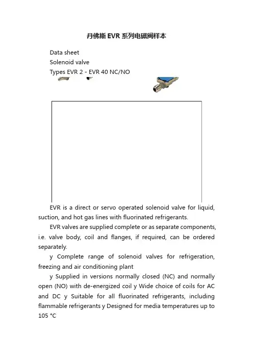
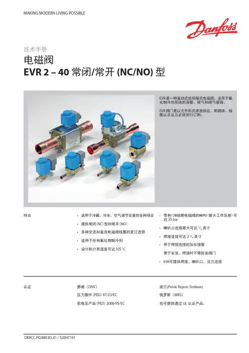
丹佛斯EVR系列电磁阀样本Data sheetSolenoid valveTypes EVR 2 - EVR 40 NC/NOEVR is a direct or servo operated solenoid valve for liquid, suction, and hot gas lines with fluorinated refrigerants.EVR valves are supplied complete or as separate components, i.e. valve body, coil and flanges, if required, can be ordered separately.y Complete range of solenoid valves for refrigeration, freezing and air conditioning planty Supplied in versions normally closed (NC) and normally open (NO) with de-energized coil y Wide choice of coils for AC and DC y Suitable for all fluorinated refrigerants, including flammable refrigerants y Designed for media temperatures up to 105 °Cy MOPD up to 25 bar with 12 W coil y Flare connections up to 5/8 in y Solder connections up to 2 1/8 iny Extended ends on solder versions make the installation easy. It is not necessary to dismantle the valve when soldering in y Available in flare, solder and flange connection versions FeaturesDet norske Veritas, DNVPressure Equipment Directive (PED) 97/23/EC Low Voltage Directive (LVD) 2006/95/ECPolski Rejestr Statków, Polen Maritime Register of Shipping, MRS Versions with UL approval can be supplied to order.ApprovalsData sheet Solenoid valve, types EVR 2 ? EVR 40 NC/NOTechnical data1) MOPD (Max. Opening Pressure Differential) for media in gas form is approx. 1 bar greater.2)Min. diff. pressure 0.07 bar is needed to stay open.RefrigerantsR22/R407C, R404A/R507, R410A, R134a, R407A, R23, R32, R290, R600, and R600a. For other refrigerants, contact Danfoss.Special note for R32, R290, R600, and R600a : Use only for system in compliance withstandard EN13463-1. Ignition risk is evaluated inaccordance with standard EN13463-1.Only EVR 2 - EVR 20 with solder connections andwithout manual stem can be applied in systemswith R32, R290, R600, and R600a as the workingfluid. For countries where safety standards are not an indispensable part of the safety system Danfoss recommends the installer to seek third partyapproval for systems containing R32, R290, R600, Note, please follow specific selection criteria stated in the datasheet for these particular refrigerants.Temperature of medium-40 –105 °C with 10 W or 12 W coil.Max. 130 °C during defrosting.Ambient temperature and enclosure for coil See separate data sheet for coils and ATEX coils.Capacity The capacity of the valve depends on the flow direction, see K v values from the table.The K v value is the water flow in [m 3/h] at a pressure drop across valve of 1 bar, ρ = 1000 kg/m 3.See extended capacity tables later in this datasheet.Table of contentsTechnical data...................................................................................................................... .......................................................2Rated capacity [kW] .................................................................................................................................................................3Ordering .............................................................. .........................................................................................................................4C apacity,Liquid .................................................................................................................. .......................................................7Capacity,Suction ............................................................................................................... ......................................................11Capacity, Hot gas ....................................................................................................................... .............................................19Design .............................................................. .. (40)Function.............................................................................................................. .......................................................................42Material specifications ................................................................................................... ......................................................43Dimensions and weights .. (45) Data sheet Solenoid valve, types EVR 2 ? EVR 40 NC/NORated liquid and suction vapour capacity is based on evaporating temperature t e = -10 °C, liquid temperature ahead of valve t l = 25 °C, pr essure drop in valve ?p = 0.15 bar.Rated hot gas capacity is based on condensing temperature t c = 40 °C, pressure drop across valve ?p = 0.8 bar, hot gas temperature t h = 65 °C,and subcooling of refrigerant ?tsub = 4 K.Rated capacity [kW]Data sheet Solenoid valve, types EVR 2 ? EVR 40 NC/NOOrdering (continued)EVR solder connections, Normally Closed (NC) - separate valve bodiesData sheet Solenoid valve, types EVR 2 ? EVR 40 NC/NOThe normal range of coils can be used for the NO valves, with the exception of the double frequency versions of 110 V, 50/60 Hz and 220 V, 50/60 Hz.Ordering (continued)EVR solder connections, Normally Open (NO) - separate valve bodiesValve bodies are supplied without flare nuts. Separate flare nuts:– 1/4 in or 6 mm, code no. 011L1101 – 3/8 in or 10 mm, code no. 011L1135 – 1/2 in or 12 mm, code no. 011L1103 – 5/8 in or 16 mm, code no. 011L1167OrderingEVR flare connections, Normally Closed (NC) - separate valve bodiesSee separate data sheet for coils.The normal range of coils can be used for the NO valves, with the exception of the double frequency versions of 110 V, 50/60 Hz and 220 V, 50/60 Hz.Data sheet Solenoid valve, types EVR 2 ? EVR 40 NC/NO Ordering (continued)Separate valve bodies, normally closed (NC)See separate data sheet for coils.Flange setsAccessoriesEVR 15 without manual operation, code no. 032F1224? in weld flange set, code no. 027N1115+ coil with terminal box, 220 V, 50 Hz, code no. 018F6701See separate data sheet for coils.ExampleCapacities are based on:– liquid temperaturet l = 25 °C ahead of valve, – evaporating temperature t e = -10 °C, superheat 0 K.Correction factorsWhen sizing valves, the plant capacity must be multiplied by a correction factor depending on liquid temperature t l ahead of valve/evaporator.When the corrected capacity is known,the selection can be made from the table.R22/R407CCorrection factors based on liquid temperature t lLiquidCapacities are based on:– liquid temperaturet l = 25 °C ahead of valve, – evaporating temperature t e = -10 °C, superheat 0 K.Correction factorsWhen sizing valves, the plant capacity must be multiplied by a correction factor depending on liquid temperature t l ahead ofWhen the corrected capacity is known,the selection can be made from the table.Correction factors based on liquid temperature t lR404A/R507Liquid (continued)Capacities are based on:– liquid temperaturet l = 25 °C ahead of valve, – evaporating temperature t e = -10 °C, superheat 0 K.Correction factorsWhen sizing valves, the plant capacity must be multiplied by a correction factor depending on liquid temperature t l ahead ofWhen the corrected capacity is known,the selection can be made from the table. Correction factors based on liquid temperature t lR290Liquid (continued)Data sheet Solenoid valve, types EVR 2 ? EVR 40 NC/NOCapacities are based on:– liquid temperaturet l = 25 °C ahead of valve, – evaporating temperature t e = -10 °C, superheat 0 K.Correction factorsWhen sizing valves, the plant capacity must be multiplied by a correction factor depending on liquid temperature t l ahead of valve/evaporator.When the corrected capacity is known,the selection can be made from the table.Correction factors based on liquid temperature t lR600Capacity Liquid (continued)Data sheetSolenoid valve, types EVR 2 ? EVR 40 NC/NOR22/R407CCorrection factorsWhen sizing valves, the evaporator capacity must be multiplied by a correction factor depending on liquid temperature t l ahead of expansion valve.When the corrected capacity is known, the selection can be made from the table.Correction factors for evaporating temperature tlCapacities are based on liquid temperature t l = 25 °C ahead of evaporator. The table values refer to the evaporator capacity and are given as a function ofevaporating temperature t e and pressure drop ?p across valve.Capacities are based on dry, saturated vapour ahead of valve.During operation with superheated vapour ahead of valve, the capacities are reduced by 4% for each 10 K superheat.Capacity SuctionData sheet Solenoid valve, types EVR 2 ? EVR 40 NC/NOCapacities are based on liquid temperature t l = 25 °C ahead of evaporator. The table values refer to the evaporator capacity and are given as a function ofevaporating temperature t e and pressure drop ?p across valve.Capacities are based on dry, saturated vapour ahead of valve.During operation with superheated vapour ahead of valve, the capacities are reduced by 4% for each 10 K superheat.Correction factors based on evaporating temperature t lCorrection factorsWhen sizing valves, the evaporator capacity must be multiplied by a correction factor depending on liquid temperature t l ahead of expansion valve.When the corrected capacity is known,the selection can be made from the table.R134aCapacity Suction(continued)Data sheet Solenoid valve, types EVR 2 ? EVR 40 NC/NOCorrection factors based on evaporating temperature t lCorrection factors When sizing valves, the evaporator capacity must be multiplied by a correction factor depending on liquid temperature t l ahead of expansion valve.When the corrected capacity is known,the selection can be made from the table.R404A/R507Capacities are based on liquid temperature t l = 25 °C ahead of evaporator. The table values refer to the evaporator capacity and are given as a function ofevaporating temperature t e and pressure drop ?p across valve.Capacities are based on dry, saturated vapour ahead of valve.During operation with superheated vapour ahead of valve, the capacities are reduced by 4% for each 10 K superheat.Capacity Suction(continued)Data sheet Solenoid valve, types EVR 2 ? EVR 40 NC/NOCorrection factors based on evaporating temperature t lCorrection factorsWhen sizing valves, the evaporator capacity must be multiplied by a correction factor depending on liquid temperature t l ahead of expansion valve.When the corrected capacity is known,the selection can be made from the table.R32Capacities are based on liquid temperature t l = 25 °C ahead of evaporator. The table values refer to the evaporator capacity and are given as a function ofevaporating temperature t e and pressure drop ?p across valve.Capacities are based on dry, saturated vapour ahead of valve.During operation with superheated vapour ahead of valve, the capacities are reduced by 4% for each 10 K superheat.Capacity Suction(continued)Data sheet Solenoid valve, types EVR 2 ? EVR 40 NC/NOCorrection factors based on evaporating temperature t lCorrection factorsWhen sizing valves, the evaporator capacity must be multiplied by a correction factor depending on liquid temperature t l ahead of expansion valve.When the corrected capacity is known,the selection can be made from the table.R290Capacities are based on liquid temperature t l = 25 °C ahead of evaporator. The table values refer to the evaporator capacity and are given as a function ofevaporating temperature t e and pressure drop ?p across valve.Capacities are based on dry, saturated vapour ahead of valve.During operation with superheated vapour ahead of valve,the capacities are reduced by 4% for each 10 K superheat.Capacity Suction(continued)Data sheet Solenoid valve, types EVR 2 ? EVR 40 NC/NOCorrection factors based on evaporating temperature t lCorrection factorsWhen sizing valves, the evaporator capacity must be multiplied by a correction factor depending on liquid temperature t l ahead of expansion valve.When the corrected capacity is known,the selection can be made from the table.R600Capacities are based on liquid temperature t l = 25 °C ahead of evaporator. The table values refer to the evaporator capacity and are given as a function ofevaporating temperature t e and pressure drop ?p across valve.Capacities are based on dry, saturated vapour ahead of valve.During operation with superheated vapour ahead of valve, the capacities are reduced by 4% for each 10 K superheat.Capacity Suction(continued)Data sheet Solenoid valve, types EVR 2 ? EVR 40 NC/NOCorrection factors based on evaporating temperature t lCorrection factorsWhen sizing valves, the evaporator capacity must be multiplied by a correction factor depending on liquid temperature t l ahead of expansion valve.When the corrected capacity is known,the selection can be made from the table.R600aCapacities are based on liquid temperature t l = 25 °C ahead of evaporator. The table values refer to the evaporator capacity and are given as a function ofevaporating temperature t e and pressure drop ?p across valve.Capacities are based on dry, saturated vapour ahead of valve.During operation with superheated vapour ahead of valve, the capacities are reduced by 4% for each 10 K superheat.Capacity Suction(continued)Data sheet Solenoid valve, types EVR 2 ? EVR 40 NC/NO Hot gas defrostingWith hot gas defrosting it is not normally possible to select a valve from condensing temperature t c and evaporating temperature t e .This is because the pressure in the evaporator as a rule quickly rises to a value near that of the condensing pressure. It remains at this value until the defrosting is finished.In most cases therefore, the valve will be selected from condensing temperature t c and pressure drop ?p across the valve, as shown in the example for heat recovery.Heat recovery The following is given: y Refrigerant = R22/R407Cy Evaporating temperature t e = -30 °C y Condensingtemperature t c = 40 °Cy Hot gas temperature ahead of valve t h = 85 °Cy Heat recovery condenser yield Q h = 8 kWThe capacity table for R22/R407C with t c = 40 °C gives the capacity for an EVR 10 as 8.9 kW, when pressure drop ?p is 0.2 bar.The required capacity is calculated as :Q table = f evaporator x f hot_temperature x Q hThe correction factor for t e = -30 °C is given in the table as 0.95.The correction for hot gas temperature t h = 85 °C has been calculated as 4% which corresponds to a factor of 1.04.Q h must be corrected with factors found: With ?p = 0.2 baris Q h = 8.71 x 0.95 x 1.04 = 8.6 kW.With ?p = 0.1 bar, Q h becomes only 6.19 x 0.95 x 1.04 = 6.1 kW.An EVR 6 would also be able to give the required capacity, but with ?p at approx. 1 bar. The EVR 6 is therefore too small.The EVR 15 is so large that it is doubtful whether the necessary ?p of approx. 0.1 bar could be obtained.An EVR 15 would therefore be too large.Result: An EVR 10 is the correct valve for the given conditions.Capacity Suction (continued)Data sheetSolenoid valve, types EVR 2 ? EVR 40 NC/NOR22/R407CAn increase in hot gas temperature t h of 10 K, based on t h = t c +25 °C, reduces valve capacity approx. 2% and vice versa.A change in evaporating temperature t e changes valve capacity; see correction factor table below.Correction factorsWhen sizing valves, the table value mustbe multiplied by a correction factor depending on evaporating temperature t e .Correction factors for evaporating temperature teCapacity Hot gas。
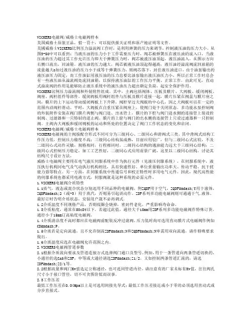
VICKERS电磁阀/威格士电磁阀样本美国威格士原装正品,假一罚十,可以提供报关证明和原产地证明等文件。
美國威格士VICKERS比例压力溢流阀工作时,是利用弹簧的压力来调节、控制液压油的压力大小。
从图3-50中可以看到:当液压油的压力小于工作需要压力时,阀芯被弹簧压在液压油的流入口,当液压油的压力超过其工作允许压力即大于弹簧压力时,阀芯被液压油顶起,液压油流入,从图示方向右侧口流出,回油箱。
液压油的压力越大,阀芯被液压油顶起得越髙,液压油经溢流阀流回油箱的流量越大o如过液压油的压力小于或等于弹簧压力,则阀芯落下,封住液压油进口。
由于油泵输出的液压油压力固定,而工作油缸用液压油的压力总要比油泵输出液压油压力小,所以正常工作时总会有一些液压油从溢流阀处流回油箱,以保持液压油缸的工作压力平衡、正常工作。
由此可见,直动式溢流阀的作用是能够防止液压系统中的液压油压力超出额定负荷,起安全保护作用。
VICKERS比例压力溢流阀和外装附件组成。
其中,主阀包括阀体、压板及膜片、大阀板、缓闭阀板、阀座、阀杆组件等部件。
缓闭阀板用阀杆组件与压板及膜片连接一起,膜片压紧在阀盖与膜片座之间,膜片的上下运动带动缓闭阀板上下升降。
阀杆穿过大阀板的中心孔,因之大阀板可以在一定的范围内沿阀杆滑动。
平时,大阀板在自重压紧在阀座上,使阀门处于关闭状态。
多功能水泵控制阀的外装附件安装在阀门膜片两侧与阀门进、出水管上,膜片的下腔与阀门进水侧的连接管上装设控制阀、过滤器和一只特制的逆止阀。
膜片的上腔与阀门的出水侧的连接管上只设过滤器和一只控制阀。
主阀内大阀板和缓闭阀板的运动和所处的位置决定了阀门工作状态的变化和启闭。
VICKERS电磁阀/威格士电磁阀样本VICKERS电磁阀的主阀按配合形式不同可分为三级同心、二级同心和滑阀式三类。
其中滑阀式结构工作压力低,控制压力精度不高;三级同心结构虽成熟,目前应用较广,但与二级同心式比较,不及二级同心式动作灵敏,规格相同,行程相同时,二级同心结构的通油能力远大于三级同心结构;二级同心式控制压力稳定,加工工艺性好,二级同心式应用前景广阔,这里以二级同心结构,讨论其结构尺寸设计方法。
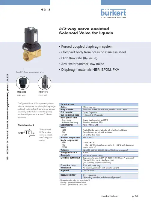
2/2-way servo assisted Solenoid Valve for liquidsThe Type 6213 is a 2/2-way normally closed solenoid valve with a forced coupled diaphragm system. It switches from 0 bar and can be used universally for fl uids. For complete opening, a differential pressure of at least 0.1 bar is necessary.Cable plugTimer unitCircuit function AServo-assisted 2/2-way valve; normally closed, with 2-way pilot control1)Measured at valve outlet at 6 bar and +20°C Opening: pressure build-up 0 to 90% Closing : pressure decay 100 to 10%Technical dataPower consumption1) Values in brackets at coil temperature 20 ºC MaterialsOrdering chart for valves (other versions on request) Valves with brass or stainless steel body, without cable plug1) Measured at +20ºC, 1 bar 2) pressure at valve inlet and free outlet2) Pressure data [bar]: Overpressure with respect to atmospheric pressure.Please note that the cable plug has to be ordered separately, see Ordering chart for accessory and separate datasheet, Type 2508* For DN 25 and DN 40 with 24 V/UC, a cable plug with an integrated high-power electronics is provided as part of the delivery. Further versions on requestPort connectionDN 10 G 1/2, 13 G 3/4, 20 G 1, NPT, RcTemperatureFKM version up to +120ºC with Epoxy coilVoltageNon-standard voltagesApprovalsUL, UR, CSASeal MaterialEPDM with KTW/FDA approvalOrdering chart for accessoryThe delivery of a cable plug includes the fl at seal and the fi xing screw. For other cable plug versions acc. to DIN EN 175301-803 Form A (previouslyDIN 43650), see separate datasheet Type 2508.Flat sealFixing screwDimensions [mm]G Thread AC coil DC coil DC and AC coil G F B H K B H K C G 1/41282.0324582.5405137.5G 3/812G 1/214G 1/21495.5324596.0405145.0G 3/416G 3/416115.53245116.0405166.0G 118To fi nd your nearest Bürkert facility, click on the orange box In case of special application conditions, please consult for advice.Subject to alterations© Christian Bürkert GmbH & Co. KG0810/4_EU-en_00891750Dimensions [mm]。
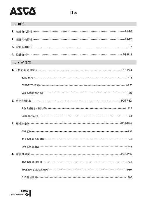
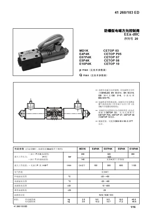
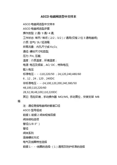
ASCO电磁阀选型中文样本ASCO电磁阀选型中文样本ASCO电磁阀选型步骤操作类型: 2通/ 3通/ 4通;工作状态: 常开/ 常闭(2/2;3/2)/ 通用(仅指2位3通电磁阀);介质: 空气/ 水/ 轻油等;所需流量:内孔尺寸或Kv,Cv,通径: 螺纹尺寸和类型;压力: Pin, 压差;温度:介质温度,环境温度;电源: 电压及频率,AC/ DC,特殊电压;输入电压标准电压---110,220/50 ;24,120,240,480/606,12,24,120,240DC非标准电压---24,100,120,200,240,380/5048,100,110,220/6028,32,38,48,100,110,220DC其它: 危险环境,手动操作器MO/MS, 手动复位,安装支架MB 等.注:通经是指电磁阀的管道口径ASCO 型号组成前缀1 前缀2 阀体规格后缀阀体结构选项管径(1/8-3”)管径阀体系列连接螺纹方式电气及线圈特性选择前缀1---线圈的选择-(1)通用及防护标准的选择美国产品通用型NEMA防爆型WBIS---本安隔爆型线圈红帽II(Type1,2,3,3s,4,4X) Type3,3s,4,4x,6,6P,7&9 前缀WBIS EExiaIICT6 IP67电气接口1/2NPT 电气接口1/2NPT无前缀电气接口1/2NPT 前缀EF 前缀JBEF 带防爆接线盒带接线端子欧洲产品IP65带DIN插头模铸隔爆 WPIS---本安型线圈II2 G/D EEx dIIC T4/T5/T6 II2 G/D EEx ia IIC T6 IP67II2 G/D NF/NL 线圈 NB(ET)线圈带接线端子带接线端子带接线端子电气接口M20X11.5II2 G/D EEx dII B T4+H2前缀1---线圈的选择-(2)线圈温度等级温度范围0℃是对通常所有阀门(包括用于介质有水锤现象)的一种标定。
华德电磁阀样本【原创版】目录1.华德电磁阀样本概述2.华德电磁阀样本的具体内容3.华德电磁阀样本的价值和意义正文一、华德电磁阀样本概述华德电磁阀样本是由百度旗下的 B2B 平台爱采购提供的一份关于华德电磁阀的产品样本。
该样本详细介绍了华德电磁阀的两款产品:4WE10E31B/CG24N9Z5L 和 4WE10G61B/CW220。
样本中包含了产品的基本信息、技术参数、工作原理以及应用领域等内容,为广大潜在客户提供了详细的产品参考资料。
二、华德电磁阀样本的具体内容1.产品基本信息华德电磁阀样本中包含的两款产品分别为:- 4WE10E31B/CG24N9Z5L:该产品是一款两位三通的电磁阀,适用于水、气、油等介质的控制。
- 4WE10G61B/CW220:该产品是一款两位四通的电磁阀,适用于水、气、油等介质的控制。
2.技术参数华德电磁阀样本中提供了两款产品的详细技术参数,包括工作电压、工作电流、功率、压力、流量等。
这些参数可以帮助客户更好地了解产品的性能和适用范围。
3.工作原理样本中详细介绍了华德电磁阀的工作原理。
电磁阀通过电磁线圈产生磁场,使得铁芯带动阀芯实现开关动作。
在电磁阀的控制下,介质可以实现自动调节、截止、切换等功能。
4.应用领域华德电磁阀广泛应用于工业自动化、机械设备、化工、石油、冶金、电力、水处理等领域。
样本中提供了丰富的应用案例,以帮助客户了解产品的实际应用效果。
三、华德电磁阀样本的价值和意义华德电磁阀样本的价值在于为客户提供了详细的产品信息,帮助客户更好地了解和选择适合自己需求的电磁阀产品。
此外,样本还有助于提高华德电磁阀品牌的知名度和影响力,拓展潜在市场。
burkert宝德电磁阀选型样本BURKERT宝德电磁阀选型样本宝德专业化的流体控制系统六十多年来,Burkert一直致力于流体控制领域的产品和系统的研发、制造,如今Burkert已发展成一个拥有三千多名员工、在德国和法国拥有五家生产厂、在全球四十多个国家和地区设立了分公司的跨国集团,成为流体控制系统领域的全球领先者。
2/2-Way direct acting solenoid valve, for high0255 pressure and temperature, DN 1-6mm, 0 -100 bar2/2-Way Solenoid Valve Direct Acting for 2200 High Pressure2/2-Way High Pressure Solenoid Valve,5404 General Purpose, PN 1-50 bar, 1/2"-1" NPT,14-355 psi2/2-Way Solenoid Valve Servo Operated for 2400 High PressureAggressive mediaClick on the typenumber to view all available documents2/2 or 3/2 way direct acting flipper solenoidvalve with isolating diaphragm; ultra low dead 6124 volume; DN 0.6mm; vacuum up to 3bar; fastresponse time; 11mm width2/2 or 3/2 way direct acting rocker solenoid6126 valve with isolating diaphragm; DN 0.8mm;vacuum up to 10bar; 16mm width2/2 or 3/2 way direct acting rocker solenoid0127 valve with isolating diaphragm; DN 1.5 or1.6mm; 0 - 2bar; 16mm width2/2-Way Miniature Solenoid Valve with 0117 Isolating Diaphragm for AnalyticalApplications, G1/8, UNF 1/4-282/2 or 3/2 way direct acting rocker solenoid 6128 valve withisolating diaphragm; DN 2 or 3mm;vacuum up to 10bar; 22mm width2/2 or 3/2 way direct acting pivoted armaturesolenoid valve with isolating diaphragm; 0124 plastic body, 0#10 bar; DN 3 up to 5mm;G1/4#2/2 or 3/2 way direct acting pivoted armature 0330 solenoid valvewith isolating diaphragm; 0 -16 bar; DN 2 up to 4mm; G1/42/2 or 3/2 way direct acting pivoted armature 0331 solenoid valvewith isolating diaphragm; 0 #16 bar; DN 2 up to 4mm; sub-base mounting2/2 or 3/2 way direct acting pivoted armaturesolenoid valve with isolating diaphragm; direct 0121 acting; 0#4 bar; DN 4 up to 8mm; G1/4#,G3/8#2/2 or 3/2-Way Direct Acting Solenoid Valve 0131 for Aggressive Fluids, Plasic Body, DN10-20mm2/2-Way Servo assisted Solenoid Valve with 6642 plasit body (PVC) DN 10-13mm, 0,5-6 bar2/2-Way Servo-assisted Solenoid Valve,0142 Plastic Body, for Aggressive Fluids, DN15-50mmTop of Page PrintWater and other neutral mediaClick on the typenumber to view all available documents2/2 or 3/2 way direct acting flipper solenoidvalve with isolating diaphragm; ultra low dead 6124 volume; DN 0.6mm; vacuum up to 3bar; fastresponse time; 11mm width2/2 or 3/2 way direct acting rocker solenoid6126 valve with isolating diaphragm; DN 0.8mm;vacuum up to 10bar; 16mm width2/2-Way Miniature Solenoid Valve, General 6011 Purpose, 0-21 bar, 0-300 psi2/2 or 3/2 way direct acting rocker solenoid 6128 valve withisolating diaphragm; DN 2 or 3mm;vacuum up to 10bar; 22mm width3/2-way Flipper Solenoid Valve, direct acting, 6144 0 - 10 bar, Sub-base, for neutral gases andliquids2/2 or 3/2 way direct acting pivoted armature 0330 solenoid valve with isolating diaphragm; 0 -16 bar; DN 2 up to 4mm; G1/43/2Way Compact Solenoid Valve, General 6014 Purpose, DN 1.5-2.5mm, 0-16 bar, 1/16-5/64,0-72 psi, Direct acting2/2 or 3/2 way direct acting pivoted armature 0331 solenoid valve with isolating diaphragm; 0 #16 bar; DN 2 up to 4mm; sub-base mounting2/2-Way Compact Solenoid Valve, General 6013 Purpose, 0-10 bar, 0-145 psi, Direct actingMini, Small and Compact solenoid valves, 2/2 6027 and 3/2-way, G1/8 - G3/8 and sub-base,brass and stainless steel valve body2/2-way solenoid valve, pilot-controlled, for 6240 neutral liquids and gases, G1/4 - G3/8, 0-16bar, switches without differential pressure2/2-Way direct acting solenoid valve, Neutral 0256 gases and liquids,DN 2-12mm, 0 - 22 bar2/2-Way direct acting solenoid valve, for high 0255 pressure and temperature, DN 1-6mm, 0 -100 bar2/2-Way Servo-assisted Solenoid Valve, 6211 General Purpose, DN 10-20mm, 0.5-10 bar2/2-Way Servo-Assisted Solenoid Valve with 6212 optional Diagnosis Function for slightlycontaminated fluids, DN 10-20mm, 0,2-10 bar2/2-Way Servo-assisted Solenoid Valve, 6213 Linked System, General Purpose, DN10-40mm, 0-10 bar2/2-Way Modular Water Valve System, 6227 servo-assisted; variableand extendable,2/2-Way, DN 10-13, 1 up to 7 bar, 14-102 psi2/2-Way Plastic Solenoid Valve, 6228 Servo-assisted, General Purpose, G3/8-G1/2,0,5-10 bar2/2-Way Solenoid Valve, Servo-assisted, 5281 General Purpose, PN0.2-16 bar, 2.8-230 psi2/2-Way Solenoid Valve for Contaminated 5282 and Aggressive Fluids, General Purpose, PN0.2-10 bar, 2.8-230 psi2/2-Way Servo-assisted Solenoid Valve,0290 Linked System, General Purpose; DN 12-50mm3/2-Way Solenoid Valve Servo-assisted with 0340 Pivoted Armature Pilot, DN 8-40mm宝德电磁阀德国宝德电磁阀 BURKERT 德国宝德电磁阀宝德电磁阀东莞巴菲特自动化设备有限公司专业代理销售德国BURKERT电磁阀全部系列BURKERT产品大量使用于分析仪器、汽车制造、生物技术、化学、电子、能源、基因工程、半导体、化妆品、食品与饮料、啤酒工业、机械工程、医疗、医药卫生、纺织、包装、水(污水)处理、卫星、太空实验、核反应堆、深海探测等领域。
力士乐62系列电磁阀样本摘要:一、力士乐62 系列电磁阀样本简介1.力士乐品牌介绍2.62 系列电磁阀的特点与功能3.样本的用途与适用范围二、力士乐62 系列电磁阀样本产品概述1.产品型号与规格2.电磁阀的工作原理3.电磁阀的主要组成部分三、力士乐62 系列电磁阀样本的技术参数1.工作介质与温度范围2.电源与信号接口3.流量与压力参数四、力士乐62 系列电磁阀样本的安装与维护1.电磁阀的安装方法与注意事项2.电磁阀的调试与操作流程3.电磁阀的维护保养与故障排除五、力士乐62 系列电磁阀样本的应用案例1.电磁阀在工业自动化领域的应用2.电磁阀在工程机械领域的应用3.电磁阀在环保水处理领域的应用正文:力士乐62 系列电磁阀样本是一款由德国力士乐公司生产的电磁阀产品样本。
力士乐作为全球知名品牌,一直致力于为客户提供高品质的工业自动化产品,而62 系列电磁阀正是其中的佼佼者。
62 系列电磁阀具有响应速度快、密封性能好、使用寿命长等特点,广泛应用于各种工业自动化控制系统中。
样本详细介绍了62 系列电磁阀的型号、规格、工作原理、技术参数以及安装与维护方法,帮助用户更好地了解和使用这一产品。
在产品概述部分,力士乐62 系列电磁阀样本详细介绍了产品型号与规格,以及电磁阀的工作原理。
电磁阀是一种利用电磁原理控制流体的开启与关闭的自动化基础元件,主要由电磁线圈、铁芯、阀体等部分组成。
在技术参数部分,样本列出了62 系列电磁阀的工作介质与温度范围、电源与信号接口以及流量与压力参数等信息,方便用户根据实际需求选择合适的电磁阀产品。
在安装与维护部分,样本为用户提供了详细的安装方法与注意事项,以及电磁阀的调试与操作流程。
此外,还介绍了电磁阀的维护保养与故障排除方法,确保电磁阀能够在各种工况下稳定运行。