样本 丹佛斯 电磁阀
- 格式:pdf
- 大小:2.20 MB
- 文档页数:28
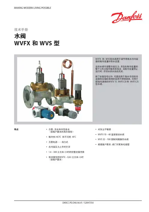
MAKING MODERN LIVING POSSIBLE特点y y介质:淡水和中性盐水(按客户要求的海水类型)yy y制冷剂:HCFC y和不可燃y HFC yy y无需电源——自力式yy y在冷凝压力上升时打开yy 1.4 – 300 立方米/小时的完整流量范围yy y低流量型的WVFX – 0,63 立方米/小时y(按客户要求)yy y对灰尘不敏感yy WVFX 10 – 40 直接驱动水阀yy WVS 32 – 100 强制伺服操作水阀y y y根据客户需求,阀门可配有毛细管技术手册水阀WVFX 和 WVS 型WVFX y和y WVS型水阀用于调节带有水冷冷凝器的制冷装置中的水流量。
这些水阀可调整冷凝压力,并且在制冷装置的整个工作过程中维持其恒定。
当制冷装置停止运行时,冷却水供水自动关闭。
除了标准型号以外,可提供用于海水冷却的冷凝器和压缩机使用的采用不锈钢阀体,可用于腐蚀性液体的WVFX 15、WVFX 20 和y WVFX 25型水阀。
参数表 水阀,WVFX 和 WVS 型技术参数1) k v值为水在通过阀的压差等于 1 bar时的流量,单位为[立方米/小时],密度ρ = 1000 千克/立方米。
2)完全打开阀则需要比使用压力范围为 3.5-16 bar的WVFX阀压力高y33%y的压力,3) WVFX 15、WVFX 20 和y WVFX 25型水阀可提供不锈钢阀体。
WVFX 10 – 40 为直接驱动调节阀yWVS 32 – 100 为伺服操作调节阀介质温度范围yWVFX 10 – 25: -25 – 130 °C yWVFX y32 – 40: -25 – 90 °C yWVS:y y-25 – 90 °C y如果一个WVS型调节器需要 1 - 10 bar y的开启压力差时,y必须更换阀的伺服弹簧。
见“订货”部分。
开启压力差yWVFX 10 – 25:yy最大 10 bar y WVFX 32 – 40:yy最大 10 bar y WVS 32 – 40:yy最小 0.5 bar:y y最大 4 bar y WVS 50 – 100:yy最小 0.3 bar;y y最大 4 bar y低于最大负荷的 20% 时,WVSy实际上将作为一个开关调节器。

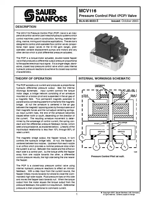
ARMATURE PIVOTFLAPPERORIFICE ORIFICENOZZLE NOZZLEC1R C 2MAGNET MAGNETPressure Control Pilot (at null).1All rights reserved. Contents subject to change.2345MCV116 SPECIFICATIONSBLN 95-9033-5Type 1Type 2U /M A 11X X A 12X X A 13X X A 14X X A 15X X A 21X X A 22X XScale Factor Delta bar/mA .165 ± .014.101 ± .010.282 ± .028.378 ± .034.866 ± .082.107 ± .010.069 ± .007Delta psi/mA 2.4 ± .2 1.47 ± .15 4.1 ± .4 5.5 ± .512.6 ± 1.2 1.55 ± .15 1.00 ± .1Typical Supply bar 34.434.434.434.434.417.217.2 Pressure psi 500500500500500250250Coil Resistance ohms 23 (32)19/15.5 (25/22)69 (92)106 (145)643 (900)23 (32)19/15.5 (25/22)Coil Inductance henries 0.0780.062/0.0470.250.399 2.250.0780.062/0.047Test Current mA ± 85± 125± 42± 40± 13± 85± 125Saturation Current mA 250350*/175**15011050250350*/175**Minimum Pressure Delta bar ± 20.7± 20.7± 20.7± 20.7± 20.7± 11.0± 11.0 Output Range Delta psi ± 300± 300± 300± 300± 300± 160± 160Typical Null as Delta bar 0 ± 0.350 ± 0.350 ± 0.350 ± 0.350 ± 0.350 ± 0.350 ± 0.35 Shipped Delta psi 0 ± 50 ± 50 ± 50 ± 50 ± 50 ± 50 ± 5Pressure Null Shift %± 2± 2± 2± 2± 2± 1.5± 1.5Temperature Null Delta bar ± 0.28± 0.28± 0.28± 0.28± 0.28± 0.21± 0.21 Shift Delta psi ± 4± 4± 4± 4± 4± 3± 3C1/C2 Null Pressure at bar 11.0 ± .6811.0 ± .6811.0 ± .6811.0 ± .6811.0 ± .687.9 ± .347.9 ± .34 Typical Supply Pressure psi 160 ± 10160 ± 10160 ± 10160 ± 10160 ± 10115 ± 5115 ± 5Internal Leakage LPM < 3.44< 3.44< 3.44< 3.44< 3.44< 3.44< 3.44cis < 3.5< 3.5< 3.5< 3.5< 3.5< 3.5< 3.5Load Flow LPM > 0.73> 0.73> 0.73> 0.73> 0.73> 0.73> 0.73cis > 0.75> 0.75> 0.75> 0.75> 0.75> 0.75> 0.75Load Pressure LPM/bar > 0.285> 0.285> 0.285> 0.285> 0.285> 0.428> 0.428 Droop Slope cis/psi > 0.02> 0.02> 0.02> 0.02> 0.02> 0.03> 0.03Hysteresis %< 9< 9< 9< 9< 9< 7< 7Symmetry %< 10< 10< 10< 10< 10< 10< 10Linearity %< 5< 5< 5< 5< 5< 5< 5Threshold mA < 1< 1< 5< 0.2< 0.05< 1< 1 Resonant Frequency Hz > 300> 300> 300> 300> 300> 350> 350Frequency Response Hz (min.)150150150150150150150 with Current Driver Maximum Voltage Volts 7.561212307.56Maximum Current mA 37537517511546375375Type 3Type 4A 31X X A 32X X A 35X X F 31X X A 42X X F 42X X G 42X XScale Factor .079 ± .007.054 ± .005.428 ± .043.079 +/-.007.079 +/-.007.079 +/-.007.079 +/-.0071.15 ± .1.78 ± .08 6.2 ± .6 1.15 +/-.1 1.15 +/-.1 1.15 +/-.1 1.15 +/-.1Typical Supply 17.217.217.224242424 Pressure 250250250350350350350Coil Resistance 23 (32)19/15.5 (25/22)643 (900)23 (32)19/15.5 (25/22)19/15.5 (25/22)19/15.5 (25/22)Coil Inductance 0.0780.062/0.047 2.250.0780.062/0.0470.062/0.0470.062/0.047Test Current ± 85± 1251685858585Saturation Current 250350*/175**50250250/125250/125250/125Minimum Pressure ± 12.4± 12.4± 12.4 Output Range ± 180± 160± 180± 180± 180± 160± 160Typical Null as 0 ± 0.1380 ± 0.1380 ± 0.1380.1 ± 0.1380.1 ± 0.1380.1 ± 0.1380.1 ± 0.138 Shipped 0 ± 20 ± 20 ± 2 1.5 ± 2 4.5 ± 2 1.5 ± 2 1.5 ± 2Pressure Null Shift ± 1± 1± 1< 1< 1.5< 1.5< 1.5Temperature Null ± 0.14± 0.14± 0.140.140.210.210.21 Shift ± 2± 2± 22333C1/C2 Null Pressure at 3.8 ± .34 3.8 ± .34 3.8 ± .34 3.5-4.110.3-11.710.3-11.7 3.5-4.1 Typical Supply Pressure 55 ± 555 ± 555 ± 550-60120-160120-16060-80Internal Leakage < 2.46< 2.46< 2.46< 2.46< 3.44< 3.44< 3.44< 2.5< 2.5< 2.5< 2.5< 3.5< 3.5< 3.5Load Flow > 0.49> 0.49> 0.49> 0.49> 0.49> 0.49> 0.49> 0.5> 0.5> 0.5> 0.5> 0.5> 0.5> 0.5Load Pressure > 0.570> 0.570> 0.570> 0.570> 0.570> 0.570> 0.570 Droop Slope > 0.04> 0.04> 0.04> 0.04> 0.04> 0.04> 0.04Hysteresis < 7< 7< 7< 7< 7< 7< 7Symmetry < 10< 10< 10< 10< 10< 10< 10Linearity < 3 < 3< 3< 3< 3< 3< 3Threshold < 1 < 1< 1< 1< 1< 1< 1Resonant Frequency > 400> 400> 400> 400> 300> 300> 300Frequency Response 150150150150150150150 with Current Driver Maximum Voltage 7.56307.5666Maximum Current 37537546375375375375* Individual coils; **Coils in series; See Pressure Control Pilot Valve (PCP) Part Number Reference Guide, page 6,for difference between F42XX and G42XX.67SPECIFICATIONS (continued)AMBIENT OPERATING TEMPERATURE-40°—93°C (-40°—200°F)OIL TEMPERATURE-29°—107°C (-20°—225°F)OIL VISCOSITY40 SSU—1400 SSULIFE10,000 hours or 10,000,000 cycles minimum WEIGHT0.73 kg (1.6 lb)HYDRAULICOPERATING SUPPLY PRESSURE10.3—68.9 bar (150—1000 psi)OPERATING RETURN PRESSURELess than 13.8 bar (200 psi)BLN 95-9033-5FLUIDThe valve is designed for use with petroleum based hydraulic fluids. Other fluids may be used provided that compatibility with viton and fluorosilicone seals is main-tained.SYSTEM FILTRATIONThe system hydraulics will have a filtration rating of B 10or better.ELECTRICALPULSE WIDTH MODULATIONWhen using a pulse width modulated current input, do not exceed rated currents for single coil devices or the algebraic sum of the rated currents in coils A and B for dual coil devices. Pulse width modulated frequencies of greater than 200 Hz are recommended.WIRINGOptional wiring styles are available: pigtail, MS, Packard Weather Pack, Packard Metri-Pack, and Deutsch DT Series.The pigtail connector is 89 mm (3.5039 in) long and is either two or four wire.As with all PCP connectors, phasing is such that a positive voltage to either red wires causes a pressure rise at the C2 port.The MS connector, MS3102C14S-2P (Sauer-Danfoss part number K01314), has four pins, two of which (A and B) are used on single coil devices. See MS Connector Pin Orien-tation, page 8. For single and dual coil wiring schemes see Connection Diagram, page 8.The mating connector for MS connectors is part number K08106 (right angle).The mating connector for Weather Pack PCPs is part num-ber K03384 (four terminal) or K03383 (two terminal). The mating connector for Metri-Pack PCPs is part number K12812(four terminal) or K10552 (two terminal). For twin two-terminal PCPs, order two K03383 bag assemblies.Included in the Weather Pack and Metri-Pack bag assembly:2 (or 4): 14—16 gauge terminals 2 (or 4): 18—20 gauge terminals1: plastic housing2 (or 4): green cable seals (for small gauge wires)2 (or 4): gray cable seals (for medium gauge wires)2 (or 4): blue cable seals (for large gauge wires)To assemble the Weather Pack and Metri-Pack mating connector:1.Isolate the wires that extend from the command source to the PCP.2.Strip back the insulation 5.5 mm (2.21653 in) on these wires.3.Push a ribbed cable seal over each of the wires with the smaller diameter shoulder of the seals toward the wire tip. Select the seals that fit tightly over the wires. The distance from the tip of the wires of the first (nearest) rib should be 9.5 mm (.37401 in). Thus, the insulation should just protrude beyond the seal.4.Select the appropriate set of terminals for the gauge wire used. Place the wire into the socket so that the seal edge is pushed through and extends slightly beyond the circular tabs that hold it in place. Crimp with a Packard 12014254 crimp tool. See Connector Crimp (Metri-Pack 280 Series), page 8. The distance from the back of the tangs to the furthest rib may not exceed 19.5 mm (.7677 in) on the Weather-Pack connector,18 mm (.7087in) on the Metri-Pack connector.5.Insert the assembled wires into the back end (large hole) of the plastic housing. Push until the wires detent with an audible click, then pull back slightly to ensure proper seating. Observe the proper phasing of the wires when installing: black wire to “A”, red wire to “B”,black to “C” and red to “D” (red to “E” if Metri-Pack).6.Swing the holder down into the detented position to trap the wires in the housing.7.Plug the two connector halves together , see Connector Parts (Metri-Pack 280 Series), page 8.8Crimp location and distance from tang to third rib of Packard Weather-Pack Connector.Packard Weather-Pack interlocked connector halves with parts identified.BLN 95-9033-5CABLE SEALSSIDE "B"R ED B LA C K SHROUDCONNECTORSIDE "A"DOUBLE-PLUG SEAL TOWER CONNECTORPackard Metri-Pack connector halves with parts identi-Crimp location and distance from tang to third rib of Packard Metri-Pack Connector.CONNECTOR CRIMP (METRI-PACK 280 SERIES)CONNECTOR PARTS (METRI-PACK 280 SERIES)CRIMP18 mm MAX.FEMALEASSYSEALSMALECONNECTOR9DEUTSCH ASSEMBLY CONTACT INSERTION AND CONTACT REMOVALCONTACT INSERTION1.Grasp crimped contact approximately 25.4 mm (1 in)behind the contact barrel.2.Hold connector with rear grommet facing you.3.Push contact straight into connector grommet until a click is felt. A slight tug will confirm that it is properly locked in place.4.Once all contacts are in place, insert orange wedge with arrow pointing toward exterior locking mechanism. The orange wedge will snap into place. Rectangular wedges are not oriented. They may go in either way.Note: Use the same procedure for the receptacle and plug.CONTACT REMOVAL1.Remove orange wedge using needlenose pliers or ahook shaped wire to pull wedge straight out.2.To remove the contacts, gently pull wire backwards,while at the same time releasing the locking finger by moving it away from the contact with a screwdriver.3.Hold the rear seal in place, as removing the contact will displace the seal.DT SERIESCONTACT PART NUMBER 0460-202-161410462-201-161410460-215-161410462-209-16141SIZE & TYPE 16 PIN 16 SOC 16 PIN 16 SOCA MAX .821.759.821.757B MIN .066.066.076.076C MAX .103.103.103.103D MIN .250.250.250.250WIRE GAGE RANGE 16 and 1816 and 1814 and 1614 and 16RECOMMENDEDSTRIP LENGTH .250 to .312.250 to .312.250 to .312.250 to .312HAND CRIMP TOOL HDT-48-00HDT-48-00HDT-48-00HDT-48-00BLN 95-9033-510D C B ABLN 95-9033-5PCP MATING CONNECTORS2-pin Packard Weather-Pack Tower Mating Connector Kit: K03383Packard Crimping and Extracting Tools: 12014254and 120140124-pin Packard Weather-pack Tower Mating Connector Kit: K03384Packard Crimping and Extracting tools: 12014254and 12014012B AA DB C4-pin MSMating Connector Kit: K08106Wiring Assembly Tool:Soldering IronA B2-pin Packard Metri-Pack Female 280 Series Mating Connector Kit: K10552Packard Crimping and Extracting tools: (two crimp-ing tools required) 12085271/12085270 and 120944294-pin Packard Metri-Pack Female 150 Series Mating Connector Kit: K26500Packard Crimping and Extracting ToolsA B C D4-pin Deutsch Plug DT Series Mating Connector Kit: K23511Deutsch Crimping and Extracting Tools: HDT-48-00 and DT/RT112434-pin Packard Metri-Pack Female 150 Series Mating Connector Kit: K22254Packard Crimping and Extracting ToolsB A2-pin Packard Metri-Pack Female 150 Series Mating Connector Kit: K22569Packard Crimping and Extracting ToolsA B C D E4-pin Packard Metri-Pack Female 280 Series Mating Connector Kit: K12812Packard Crimping and Extracting toolsD C B AAPPLICATION (continued)Many controllers are set up to drive proportional solenoids through pulse width modulation (PWM). Sometimes the scheme is used with the field effect transistor (FET) outputs of DC2s or SUSMIC controllers. These controls send an oscillating pulse width modulated dc current to the coil. This scheme has the advantages of providing dither to the actua-tor and, in some cases, can simplify the electronics since they operate in a digital mode, potentially reducing heat output from the device.As with most things there are trade offs or unwanted side effects: Items 1 through 3 apply to all electrohydraulic actuators. Items 4 and 5 relate more specifically to PCPs.1.The pulsing current generates unwanted electromag-netic radiation, which can interfere with related devices.2.The actuators are generally responsive to current.PWM valve drivers are generally low impedance volt-age drives. As the coils heat up, the resistance changes (typically by as much as 50%), thus altering the re-sponse of the device. For a given PWM frequency and duty cycle, both peak and average current into the driven coil may strongly affect the coil's L/R (induc-tance/resistance) time constant, potentially reducing both accuracy and linearity. The effects vary consider-ably with valve type and with temperature and are quite different between the Sauer-Danfoss MCV116 and MCV110. PWM drivers often require "current feedback"to maintain sufficient accuracy as the temperature var-ies over the operating range.3.Some controllers are designed to diagnose shorts oropens in the output circuit. The PWM-induced voltage can affect some common detection schemes.4.In the case of the PCP, a PWM signal is like analternating current applied to the primary of a trans-former. A voltage is induced in the secondary coil proportional to the turns ratio of the coils less losses in the magnetic circuit. If the secondary coil is open circuited, there is no effect since no current flows, hence no magnetic field is generated. However, if current is allowed to flow in the secondary coil, it flows in a direction which will reduce the output of the actuator.5.Most electronic drivers will conduct current when backdriven with excessive voltages. One example is a drive that contains non-linear devices such as diodes or zener diodes for re-circulatory currents. The induced voltages may be sufficient to cause these devices to conduct, thereby causing current flow in the non-driven coil.In position control systems where the control drives toward null this generally is not a problem. However, in propel systems, especially dual path propel systems, the change in output velocity could be a severe limita-tion. In some cases filters can be designed to correct the problem. A limitation of filters is this adds a lag in the circuit which will adversely affect high response sys-tems. Also, it is impossible to design one filter to fit all applications.In summary, the ability to drive the Sauer-Danfoss PCP depends on many circumstances which must be understood and accounted for by the user.FREQUENTLY ASKED QUESTIONSThe following questions and answers cover those applica-tions that use the PCP as the pilot stage to a second stage. For example: Electrical Displacement Control (EDC) for Sauer-Danfoss Variable Pumps and Sauer-Danfoss Flow and Pressure Control Servovalves.1.Question: Is the PCP a 12 or 24 volt dc device (i.e.,direct battery voltage)?Answer: Do not apply 12 or 24 volts dc directly to the PCP for several reasons, the most important being the coil will be permanently damaged. And voltage levels beyond 3 volts dc are out of the control range. The exceptions are: (1) the low current (4-20 mA) models, which have a maximum voltage ratting of 36 V DC, and(2) when applying a PWM signal from an amplifier. 2.Question: Why are some PCP configurations singlecoil and some dual coil?Answer: The original design was a single coil, and the dualcoil design followed as the standard configuration.3.Question: When should either a dual coil or single coilbe specified?Answer: When uncertain, specify a dual coil. The second coil does not have to be used to be bi-directional when using a potentiometer type inputs. The dual coil configuration can simplify the switching logic when required. The one exception in which a dual coil is not offered are EDCs and Servovalves that have a current range of 4-20 mA.4.Question: When is it a must to use a dual coil?Answer: When using a Control Handle (MCH) that hasa circuit board built into the housing (e.g., MCHxxxLxxx),because the output is switched forward and reverse between two output terminals. This switched output current is approximately 0—3 volts. With this type of output scheme, use one coil for reverse and the other coil for forward. However, most MCH models have a voltage/current output based on a bridge circuit, which uses approximately a 6 volt reference on each of the two outputs terminals. As the MCH is moved between forward and reverse, the voltage swings up and down from 6 volts. Also, when using either an analog amplifier or a microcontroller both coils would be used to achieve bi-directional control.5.Question: Can the PCP alone be changed on an EDCto achieve 4-20 mA control?Answer: Simply changing the PCP is not a solution, because the second stage (i.e., EDC) is calibrated using different internal spring forces to match a specific high gain (psid/mA) PCP (MCV116A3501).6.Question: What is the purpose of having silicone oilinside the cover?Answer:The original PCP Valves design did not have silicone oil, but shortly thereafter it was added to all PCP models to reduce the effects of the environment. The loss of silicone oil to those PCP's that are used on the Servovalve (KVF models) may cause a loss in valve performance, and therefore it is recommended to re-place the silicone oil in the event it is removed or lost.See item 6 on page 13 for replacement kit.1114Note: The Deutsch electrical connectors are not shown. See Item 4, a change was made in January 2000 that increased the null access opening thread size from 1/4-28 to 3/8-24, therefore part number K00920 only fits those covers with a 1/4-28 thread size. See Item 5, the preferred part number K28475 includes the cover,The following steps are recommended when servicing those parts listed in the Service Parts List, page 13.Preferred service tools are:• Screw driver: TX 15 and TX 10• Solder: SN62• Needle nose pliers, small tip • Solder iron: electronic type • Multimeter• Cleaning solvent: Chemtronics 2000 ES 1601• Torque wrench: 0—25 in .lb (0—33 N .m)REPLACING COVER AND/OR ELECTRICAL CONNECTOR 1.Wipe down external surface to ensure that loose contaminants will not fall inside the housing.2.Place the valve in a firm position at 45° with the electrical connector tilted upwards. Pressure control pilot valves (PCP) built after 1988 are filled with a silicone oil. Locate and remove the four connector screws (see page 13,Item 8 if MS connector, or Item 10 if Packard connector).3.Hold the electrical connector and untwist wires by rotating the connector counterclockwise two turns while gently pulling away from the housing.4.Clean the solder connections inside connection of the electrical connector with degreaser. Unsolder the wires,noting which pin goes to which wire color (e.g., Pin A to black, Pin B to red, Pin C to brown, etc.). With the connector held firmly, place the solder iron against the base solder cup if MS, and pin if Packard, until the wires can be gently pulled away.5.The cover can now be removed and replaced if required.Be sure the PCP cover gasket is firmly seated into the cover base and is in good condition before cover is installed. Torque cover screws to 12—15 in .lb (16—20N .m).6.Verify that wire to pin connections are correct before soldering wires and the connector O-ring (see page 13,Item 7) is in place before soldering.7a.For the MS style connector, ensure that the cups havesufficient solder (approximately level). If additional solder is required, place solder iron against the base of the cup and add solder. While solder is still liquid, place wire in the cup, remove iron and let cool for several seconds while holding wire firmly.7b.For the Packard style connector, the wire should extendaround and contact the terminal post for at least 180° (1/2 wrap to a maximum of 270°). When ready to solder,heat the terminal and add solder, remove iron, and let cool for several seconds while holding wire firmly.8.After soldering, ensure that terminals and wires do not contact one another.SERVICE PARTS (continued)9.If silicone oil is to be added, do so at this step with the connector not yet attached to cover. Tilt cover upward and add 45 cc of oil from container. The container (see page 13, Item 6) holds enough for 3 fills.10. Before attaching the connector to the cover, rotateconnector clockwise two turns. This will bundle the wires together, finishing with the notch up when viewed from the outward side of the MS connector and lead wires down for Packard connector (see MS Connector Pin Orientation, page 8). Insert connector screws and torque to 8—10 in .lb (11—13 N .m).11. With a multimeter, check for proper coil resistancebetween terminals A and B, and between C and D if PCP is a dual coil.CUSTOMER SERVICEWhen ordering a MCV116 Pressure Control Pilot Valve refer to the table MCV116 Pressure Control Pilot (PCP) Valve Part Number Reference Guide, page 6.NORTH AMERICAORDER FROMSauer-Danfoss (US) CompanyCustomer Service Department3500 Annapolis Lane NorthMinneapolis, Minnesota 55447Phone: (763) 509-2084Fax: (763) 559-0108DEVICE REPAIRFor devices in need of repair, include a description of the problem, a copy of the purchase order and your name, address and telephone number.RETURN TOSauer-Danfoss (US) CompanyReturn Goods Department3500 Annapolis Lane NorthMinneapolis, Minnesota 55447EUROPEORDER FROMSauer-Danfoss (Neumünster) GmbH & Co. OHG Order Entry DepartmentPostfach 2460, D-24531 NeumünsterKrokamp 35, D24539 Neumünster, Germany Phone: +49 4321 871-0Fax: +49 4321 871 122。

丹佛斯-AKS41-ICAD-EKC347电动阀使用说明书丹佛斯 AKS41 ICAD EKC347电动阀使用说明书本系统采用Danfoss的一套组合(AKS41液位传感器+(ICM+ICAD封闭式电动阀)+EKC347控制器)进行供液控制。
EKC347控制器可以根据AKS41液位传感器提供的4~20mA液位信号来精确控制ICM封闭式电动阀的开度。
以下分别给出AKS41液位传感器、ICAD电动阀马达(电动阀)、EKC347控制器的中文操作指南,如果与英文操作指南有冲突,以英文为准。
一、AKS41液位传感器、ICAD电动阀马达、EKC347控制器的初始设定AKS41液位传感器、ICAD电动阀马达、EKC347控制器必须进行初始设定。
1.1、液位控制器EKC347的设定设定●上电几秒,待显示0.00后,才允许开始设定;●同时按住两按钮,进入液位设定状态,显示值会不断闪动,按上下键调定设定值,设定完后再同时按住两键进行确认;●接着上步操作,按住上面的按键不放几秒钟后,可找到其它设置项r06、r12等进行设置;●待所有参数均设定完毕后,放开所有按键,一段时间后,显示自动恢复到原始画面。
注意:显示r12等设定项后,同时按住两键进入参数设定状态,通过按上下两键调定具体设定值,参数值设定完毕后,务必再次同时按住两键进行确认。
LED显示:当前实际液位值,按一下“下按键”,则LED显示为电动阀开度。
具体设定值参见以下表格:1.2、电动阀ICAD马达初始设定●按住中间的○按键几秒钟后,按▲▼键找到i10项,按下○键进入密码输入状态,再通过▲▼键找到密码值(密码为11),然后再按一下○键进行确认;●输入密码后便可以对参数进行设定了,按▲▼键找到需要设定的项,然后按○键,进入参数设定状态,通过按▲▼键设定参数值,参数设定完后,再按一下○键进行确认;设定完后电动阀会进行自动调节,发出嗡嗡的震动,且显示100%,说明设定正确。

丹佛斯丹佛斯液压马达包括OMM系列OMP系列OMH系列OMR系列OMEW系列OMS系列OMV系列OML系列等各种型号。
丹麦丹佛斯DANFOSS啮合齿轮泵丹佛斯DANFOSS液压马达丹佛斯DANFOSS液压阀丹佛斯DANFOSS液压摆线马达丹佛斯DANFOSS液压泵丹佛斯DANFOSS伺服阀DANFOSS丹佛斯马达OMR250-151-0247丹佛斯压力开关ACB-UB13W 2.8NC 2.1 061R8190丹佛斯电磁阀EV220B32及线圈220V还有一下型号:OMM32 151G0003 OMVS800 151B3129 MCV116G4201 SNP1/3 8DC001F SNP2/11DSC011 OMS12.5 151G0001+151G0211 OSQB8 151F0081 OMT500 151B3005 OMM20 151G0002 OMS250 151F0505 OMS250 151F0512 OMV500 151B3102 OMV630 151B3108OMV800 151B3104 OMV800 151B3109 VT6CC-031-020-2R00C100 OMP200 151-0615 OMS315 151F0506 OMM12.5 151G0001+Flange 151G0211 OSQB8 150F0081 OMT500 OMV630 151B3108 OMS250 151F0505 OMS250 151F0512 OMV500 151B3102OMV630 151B3108 OMV800 151B3104 OMV800 151B3109 OMP200 151-0615OMS315 151F0506 OSPBX400LS 150-1081 MCV116A3501 S/N 1201749OMH500 151H1006 OMH500 151H1016 OSQB8 15OF0081 OMS200 151F0504OMV315EM 151B3150 OML32 151G2004 OMR80 151-0411 OMR100 151-0412OSQB8 151F0081 OMH500 151H1046 151H1026 151H1056 151H1081 151H1036OMS160 151F0503 OMT200 151B3013 OMVS800 151B3129 OMS315 151F0513OMS125 151F0502 OMR100 151-0702 OMS315 151F0111 OMS315 151F0513OMS315 151F2213 OMS200 151F0504 OMS315 151F0506 OMP400 151-5009OMTS250 151B3038 OMT200 151B3001 OMVS800 151B3129 OMVW630 151B3123OMS315 151F0548 OMSW250 151F0533 OMSS125 151F0237 OMT200 151-B3001OMVS800 151-B3129 OMVW630 151F0548 SNP1/3 8DC001F OMVS500 151B3127OMR250 151-0716 OMR125 151-0713 OMR100 151-0712 OMR200 151-0715OMR200 151F0214 OMR100 151-0212 OMP50 151-0330 OMT200 151B3001OMM32 151G0003 OMSS-200 151F0539 OMSS-400 151F0608 OMVW630 151B3123OMS80T 151F0575 OMVW800 151B3124 OMS160 161F0545 OMP400 151 5009OMS315 151F0213 OMS200 151F0211 OMTS315 151B3039 OMT200 151B3001OMS80 151F0500-3 OMP400 151-5009 OMP400 151-0618 OMP400 151-0608OMV800 151B3109 OMH-200 151H1002 OMS160 151F0503 OMF315 151B30032151F0232 OMT500 151B3005 OMR250 151-0216 OMR125 150-0209OMT400(接口尺寸G3/4)151B3004 OMSS 125(接口尺寸R1/2)151F0537OMR 200(接口尺寸G1/2)151-0214 OMT 400(接口尺寸G3/4)151B3004OMS315 151F0213 OMS200 151F0211 OMS80T 151F0575 MCV116G4201MCU116A3501 S/N1206461 SNP2/6DC002 OMTS315 151B3039 OMT200 151B3001液压泵SNP2/17 D CO 01 1F OMP315 151-0033 OMR250-151-02065OMS315-15F0506-3 OMH200-151H-1002 OMTS250-151B-3038 OMT400T 151B3057 OMR50 1510410 OMM12.5 OMP50 OMP400 151-5009 OMP400 151-0618OMP400 151-0608 OMV800 151B3109 OMH-200 151H1002 151F0504OMS200151F0504-3 OMR200151-0214-5 OMT400151B-3004-2 151F0503151B30032 OMT200 151B3001 OMV800 151B3104 OMS80T 151F0575OMS200 EM 151F3024 OMS315 151F0506 151F0232 OMT500 151B3005OMR250 151-0216 OMR125 150-0209 转向控制阀OSPC 80 CN150 N 0173 086D2400" OMTS250 151B3038 OMP50 D25 151-0610OMTS-200 151B3037 OMTS-160 151B3036 OMTS-250 151B3038OMR200 150-0214 OMH200 151H1002 OMP315 151-0033 OMR50 151-0410OMR100 151-0412 OMR160 151-0414 OMV500 151B-3102 OMV500 151B-3107OMS12.5 151G0001+151G0211 OSQB8 151F0081 OMT500 151B3005OMM20 151G0002 OMS250 151F0505 OMS250 151F0512 OMV500 151B3102OMV630 151B3108 OMV800 151B3104 OMV800 151B3109 VT6CC-031-020-2R00C100 OMP200 151-0615 OMS315 151F0506 OMM12.5 151G0001+Flange 151G0211OSQB8 150F0081 OMT500 90R55KA1NN80P3 SID03GBA292924OMS250 151F0505 OMS250 151F0512 OMV500 151B3102OMV630 151B3108 OMV800 151B3104 OMV800 151B3109 OMS315 151F0506 OSPBX400LS 150-1081 MCV116A3501 OMH500 151H1006 OMH500 151H1016 OSQB8 15OF0081 OMS200 151F0504 OMV315EM 151B3150 OML32 151G2004OMR80 151-0411 OMR100 151-0412 OSQB8 151F0081 OMH500 151H1046151H1026 151H1056 151H1081 151H1036 OMS160 151F0503 OMT200 151B3013 OMVS800 151B3129 OMS315 151F0513 OMS125 151F0502 OMR100 151-0702 OMVS500 151B3127 OMR250 151-0716 OMR125 151-0713 OMR100 151-0712OMR200 151-0715 BF20-75/D09LA4TF 1998591 OMR200 151F0214OMR100 151-0212 OMP50 151-0330 OMT200 151B3001 OMM32 151G0003OMSS-200 151F0539 OMSS-400 151F0608 OMVW630 151B3123 OMS80T 151F0575 OMP.160 N134.OMP.160.150.0614.8 OMV W800 151B3124 OMS160 161F0545OMP400 151 5009 OMS315 151F0213 OMS200 151F0211 OMTS315 151B3039OMT200 151B3001 OMS80 151F0500-3 OMP400 151-5009 OMP400 151-0618OMP400 151-0608 OMV800 151B3109 OMH200 151H1002 OMS160 151F0503OMF315 151B30032 转向控制阀"OSPC 80 CN 150 N 0173 086D2400"151F0232 OMT500 151B3005 OMR250 151-0216 OMR125 150-0209OMT400(接口尺寸G3/4)151B3004 OMSS 125(接口尺寸R1/2)151F0537OMR 200(接口尺寸G1/2)151-0214 OMT 400(接口尺寸G3/4)151B3004OMS315 151F0213 OMS200 151F0211 OMS80T 151F0575Valve drive mplifier KE04110 03135287 Valve drive mplifierKE04110 03135286 行走泵90R42电液伺服阀MCV116G42010524-MCU116A3501 S/N 1206461" 泵SNP2/6 DC002伺服阀D633-308B OMTS315 151B3039 OMT200 151B3001 阀M46-20751MPV046CBBHTBBBAAAB FFCBA GG ANNN 液压泵SNP2/17 D CO 01 1FOMP315 151-0033 OMR250-151-02065 OMS315-15F0506-3OMH200-151H-1002 OMTS250-151B-3038 OMT400T 151B3057 OMR50 1510410 OMM12.5 OMP50 OMP400 151-5009 OMP400 151-0618 OMP400 151-0608OMV800 151B3109 OMH-200 151H1002 151F0504 OMS200151F0504-3OMR200151-0214-5 OMT400151B-3004-2 151F0503 151B30032OMT200 151B3001 OMV800 151B3104 OMS80T 151F0575 OMS200 151F3024OMS315 151F0506 151F0232 OMT500 151B3005 OMR250 151-0216OMR125 150-0209 转向控制阀"OSPC 80 CN 150 N 0173 086D2400"OMTS250 151B3038 OMP50 D25 151-0610 OMTS-200 151B3037OMTS-160 151B3036 OMTS-250 151B3038 OMR200 150-0214 OMH200 151H1002OMP315 151-0033 OMR50 151-0410 OMR100 151-0412 OMR160 151-0414OMV500 151B-3102 OMV500 151B-3107 OMVS800 151B-3129 OMP25 151-0340OMP32 151-0341 OMP40 151-0342 OMP50 151-0310 OMP80 151-0311OMP100 151-0312 OMP125 151-0313 OMP160 151-0315 OMP200 151-0315OMP250 151-0316 OMP315 151-0317 OMP400 151-0318 OMP25 151-0640OMP32 151-0641 OMP40 151-0642 OMP50 151-0610 OMP80 151-0611OMP100 151-0612 OMP125 151-0613 OMP160 151-0614 OMP200 151-0615OMP250 151-0616 OMP315 151-0617 OMP400 151-0618 OMP50 151-1208OMP80 151-1209 OMP100 151-1210 OMP125 151-1217 OMP160 151-1211OMP200 151-1212 OMP250 151-1213 OMP315 151-1214 OMP400 151-1215OMP50 151-5191 OMP80 151-5192 OMP100 151-5193 OMP125 151-5194OMP160 151-5195 OMP200 151-5196 OMP250 151-5197 OMP315 151-5198OMP400 151-5199 OMP50 151-0300 OMP80 151-0301 OMP100 151-0302OMP125 151-0303 OMP160 151-0304 OMP200 151-0305 OMP250 151-0306OMP315 151-0307 OMP400 151-0308 OMP50 151-0600 OMP80 151-0601OMP100 151-0602 OMP125 151-0603 OMP160 151-0604 OMP200 151-0605151F0222 151F0223 151F0224 151F0225 151F0226 151F0222 151F0223 151F0224151F0225 151F0226 151F0227 151F0310 151F0227 151F0310 151F0521 151F0521151F0522 151F0523 151F0524 151F0525 151F0526 151F0522 151F0523 151F0524151F0525 151F0526 151F0527 151F0610 151F0527 151F0610 151F0228 151F0228151F0229 151F0230 151F0231 151F0232 151F0233 151F0229 151F0230 151F0231151F0232 151F0233 151F0234 151F0309 151F0234 151F0309 151F0528 151F0528151F0529 151F0530 151F0531 151F0532 151F0533 151F0529 151F0530151F0531151F0532 151F0533 151F0534 151F0609 151F0534 151F0609 OMSB80 OMSB100OMSB125 OMSB160 OMSB200 OMSB250 OMSB315 OMSB400 OMSB80 OMSB100 OMSB125 OMSB160 OMSB200 OMSB250 OMSB315 OMSB400 151F0068 151F0069 151F0070151F0068 151F0069 151F0070 151F0071 151F0071 151F0668 151F0669 151F0670151F0668 151F0669 151F0670 151F0671 151F0671 151F0075 151F0076 151F0077151F0075 151F0076 151F0077 151F0078 151F0078 151F0675 151F0676 151F0677151F0675 151F0676 151F0677 151F0678 151F0678 OMS100 OMS200 OMS250OMS315 OMS400 OMSW80 OMSW100 OMSW100 OMSW125 OMSW160 OMSW143 OMSW200。
丹佛斯pm主阀原理
丹佛斯PM主阀是一种控制多个设备的减压控制阀,它能够控制多个设备的压力以确保运行的稳定性和安全性。
它工作原理是,当设备的压力超出预设上限时,PM主阀就会开启,以排出多余的压力,以防止设备的运行状况受到不良影响。
丹佛斯PM主阀是一种纯电磁阀,由电磁马达驱动,可以根据不同的压力配置实现减压控制,也就是说可以控制低于预设压力的最大值。
当设备压力逼近预设压力时,PM主阀会自动开启,以取得最佳节能效果。
此外,PM主阀还具有良好的阻尼效果,能够缓冲压力变化,防止因过大的压力变化而影响设备的性能和使用寿命。
丹佛斯PM主阀的另一个优点是其独特的带电磁的设计。
这种设计使其能够监测和控制压力,而无需人工介入。
它还可以让操作变得更加有效率,因为它能够根据不同的压力状态智能地调节阀门的位置,而不需要人工操作。
总之,丹佛斯PM主阀是一种高效且安全的压力控制阀,它能够用于减压控制多个设备,从而确保风机、发动机和气动设备的良好运行,提高工作效率。
此外,它还具有简单易操作、节能环保等特点,是工业设备的理想选择。
Revised 10/01/88I–3557-SWet Armature Solenoid Operated Directional ValveDG4S*-01*A-W(3)-*-50Service GuideVickers by Danfoss®Directional ValvesAX439457235961en-000101’d) (F3 Viton - 5 req’d)Model CodePrinted in U.S.A.For satisfactory service life of these components, use full ow ltration to provide uid which meets ISO cleanliness code 20/18/15 or cleane r. Selections from Danfoss OF P, OFR, and OFRS series are recommended.Danfoss Power Solutions is a global manufacturer and supplier of high-quality hydraulic and electric components. We specialize in providing state-of-the-art technology and solutions marine sector. Building on our extensive applications expertise, we work closely with you to ensure exceptional performance for a broad range of applications. We help you and other customers around the world speed up system development, reduce costs and bring vehicles and vessels to market faster.Danfoss Power Solutions – your strongest partner in mobile hydraulics and mobile Go to for further product information.outstanding performance. And with an extensive network of Global Service Partners, we also provide you with comprehensive global service for all of our components.Local address:DanfossPower Solutions GmbH & Co. OHG Krokamp 35D-24539 Neumünster, Germany Phone: +49 4321 871 0DanfossPower Solutions ApS Nordborgvej 81DK-6430 Nordborg, Denmark Phone: +45 7488 2222DanfossPower Solutions (US) Company 2800 East 13th Street Ames, IA 50010, USA Phone: +1 515 239 6000DanfossPower Solutions Trading (Shanghai) Co., Ltd.Building #22, No. 1000 Jin Hai Rd Jin Qiao, Pudong New District Shanghai, China 201206Phone: +86 21 2080 6201Danfoss can accept no responsibility for possible errors in catalogues, brochures and other printed material. Danfoss reserves the right to alter its products without notice. This also applies to productsagreed.All trademarks in this material are property of the respective companies. Danfoss and the Danfoss logotype are trademarks of Danfoss A/S. All rights reserved.© Danfoss | December 2022•Cartridge valves •DCV directional control valves•Electric converters •Electric machines •Electric motors •Gear motors •Gear pumps •Hydraulic integrated circuits (HICs)•Hydrostatic motors •Hydrostatic pumps •Orbital motors •PLUS+1® controllers •PLUS+1® displays •PLUS+1® joysticks and pedals•PLUS+1® operator interfaces•PLUS+1® sensors •PLUS+1® software •PLUS+1® software services,support and training •Position controls and sensors•PVG proportional valves •Steering components and systems •TelematicsHydro-GearDaikin-Sauer-Danfoss。
丹佛斯比例阀接线方法嘿,朋友们!今天咱就来唠唠丹佛斯比例阀接线这档子事儿。
你说这丹佛斯比例阀啊,就像是机器世界里的小精灵,得给它接好线,它才能欢快地工作呢!那接线咋弄呢?听我慢慢道来。
首先呢,你得准备好工具,就像战士上战场得有趁手的兵器一样。
螺丝刀啊、剥线钳啊,这些可都不能少。
然后,找到比例阀上的接线端子,这就好比是找到小精灵的家。
看着那些小小的接线端子,可别小瞧它们,它们就像是电路世界的小入口,接对了路,一切都顺顺利利,接错了,那可就麻烦喽!就好像你本想去东边,结果走反了方向去了西边,能行不?把线的外皮剥开一点,露出里面的金属丝,这就像是给小精灵准备好礼物。
然后小心翼翼地把金属丝插进接线端子里,拧紧螺丝,就好像给小精灵关上家门,让它安心待在里面。
这时候你可能会问了,要是接错了咋办呀?嘿,那可就好比是走岔了路,得赶紧回头重新走啊!可不能马虎大意。
你想想看,要是接线没接好,这比例阀能好好工作吗?就像人要是腿不舒服,还能跑得快吗?所以啊,咱得认真对待,不能敷衍了事。
而且啊,在接线的过程中,还得注意安全。
电这玩意儿可不是好惹的,不小心碰到了,那可不得了。
就跟遇到一只小老虎似的,得小心应付。
接完线后,别着急,再检查检查,看看有没有松动的地方,有没有接错的地方。
就像出门前得照照镜子,看看自己穿戴整齐了没有。
总之呢,丹佛斯比例阀接线这事儿,说简单也简单,说难也难。
关键就看你用不用心,仔不仔细。
要是你认真对待,那它就能乖乖为你服务;要是你马马虎虎,那它可就没准给你闹出啥乱子来。
所以啊,朋友们,可别小瞧了这小小的接线工作,它可是关系到整个系统能不能正常运行的关键呢!大家都记住了吗?。