清华大学断裂力学讲义ch6-复合型断裂判据
- 格式:ppt
- 大小:3.55 MB
- 文档页数:21
Chapter Five Fracture criterion for mixed mode crackIn the material mechanics, for the multiaxial stress state, four strength theories have been developed. In the fracture mechanics for the mixed mode crack problem, we need to develop the fracture theory accordingly. Many fracture theories have been developed. Two key questions must be answered.(1) What direction does a crack propagate along?(2) What is the critical case?In what follows, five theories will be introduced.§5-1 Maximum normal stress criterionMaximum stress criterion can be applied to the mixed mode crack of mode I and mode II.The asymptotic stress solution is)23cos 2cos 2(2sin 2)23sin 2sin 1(2cos 2θθ+θπ-θθ-θπ=σrK r K II I xx 23cos 2cos 2sin 2)23sin 2sin 1(2cos 2θθθπ+θθ+θπ=σr K r K II Iyy )23sin 2sin 1(2cos 223cos 2sin 2cos 2θθ-θπ+θθθπ=σrK r K II I xy By application of the coordinate transformation formulas, we can obtain the expressions of three stress components in the polar coordinates (r , θ). The circumferential normal stress is]sin 3)cos 1([2cos 2121θ-θ+θπ=σθθII I K K r The circumferential normal stress intensity factor θθK is defined as]sin 3)cos 1([2cos 212lim 0θ-θ+θ=σπ=θϑ→θθII I r K K r KHence, θθσ can be written asr K π=σθθθθ2Assumptions:(1) Crack initiation direction is the direction of the maximum θθK ;(2) When θθK reaches its critical value c K θθ, break occurs. c K θθ is a material constant.The crack initiation angle 0θ can be determined from0=θ∂∂θθK , 022<θ∂∂θθK The result is0)1cos 3(sin 00=-θ+θII I K K0)5cos 9(2sin )cos 31(2cos 0000<+θθ+θ-θII I K K The critical condition is c II I K K K K θθθ=θ-θθ=)sin 232cos (2cos0020maxDetermination of c K θθ:For mode I crack, 0≠I K , 0=II K , 00=θ, the critical condition reduces to c Ic K K K θθθ==maxNote that c K θθ is a material constant. When, 0≠I K and 0≠II K , there still prevails Ic c K K =θθ. The maximum stress criterion is expressed asIc II I K K K ≤θ-θθ)sin 232cos (2cos 0020Application to mode II crack:For a mode II crack, 0=I K and 0≠II K . The crack initiation angle can be solved,o 5.700-=θ. FromIc c II I K K K K K ==θ-θθ=θθθ)sin 232cos (2cos 0020max one can obtain thatIc IIc K K =149.1, Ic IIc K K 87.0=,The fracture criterion for Mode II crack can be derived from the maximum stress criterion thatIIc II K K ≤It is convenient for the engineering application. However, there is no difference between the plane stress and plane strain.§5-2 Maximum normal strain criterionNear the crack tip, the circumferential normal strain is]}2sin )1cos 3(2cos sin 3[2cos )]cos 3()cos 1[({2121)(111111θ-θν+θθ-θθ-ν-θ+π=σν-σ=εθθθθII I rr K K E r E E E =1, νν=1, for plane stress; 211ν-=E E , ννν-=11, for plane strain. The circumferential normal strain intensity factor *θθK is defined as]}2sin )1cos 3(2cos sin 3[2cos )]cos 3()cos 1[({212lim 1110*θ-θν+θθ-θθ-ν-θ+=επ=θθ→θθII I r K K E r K Then,r K π=εθθθθ2*Assumptions:(1) Crack initiation direction is the direction of the maximum *θθK ;(2) When *θθK reaches its critical value *c K θθ, break occurs. *c K θθ is a materialconstant.The cracking angle 0θ satisfies0*=θ∂∂θθK , 02*2<θ∂∂θθK The critical value *c K θθ can be determined by Ic K . For Mode I, 0=II K , 00=θ. It can be obtained thatIc c K E K 11*1ν-=θθ The maximum normal strain criterion isIc II I K K K ≤θ-θν+θθ-θθ-ν-θ+ν-}2sin )]1cos 3(2cos sin 3[2cos )]cos 3()cos 1[({)1(210010000101Now the plane stress and plane strain can be distinguished.§5-3 Strain energy density factor theoryStrain energy density factor theory was proposed by Prof. G . C. Sih that can be applied to the three dimensional problem.When, 0≠I K , 0≠II K , 0≠III K , the asymptotic stress solution is)23cos 2cos 2(2sin 2)23sin 2sin 1(2cos 2θθ+θπ-θθ-θπ=σrK r K II I xx 23cos 2cos 2sin 2)23sin 2sin 1(2cos 2θθθπ+θθ+θπ=σr K r K II Iyy )23sin 2sin 1(2cos 223cos 2sin 2cos 2θθ-θπ+θθθπ=σrK r K II I xy 2sin 222cos 22θπν-θπν=σr K r K II I zz 2cos 2θπ=σrK III yz , 2sin 2θπ-=σr K III zx The strain energy density w is)(21)()(21222222zx yz xy xx zz zz yy yy xx zz yy xx E E w σ+σ+σμ+σσ+σσ+σσν-σ+σ+σ= The strain energy density w can be expressed in the form ofrS w = where233222122112IIIII II I I K a K a K K a K a S +++=, strain energy density factor )cos )(cos 1(16111θ-κθ+πμ=a )1cos 2(sin 16112+κ-θθπμ=a )]1cos 3)(cos 1()cos 1)(1[(16122-θθ++θ-+κπμ=a πμ=4133a Assumptions: it is physics, not mathematics.(1) Crack initiation direction is the direction of the minimum S ;(2) When S reaches its critical value c S , break occurs. c S is a material constant.The cracking angle 0θ can be solved from0=θ∂∂S , 022>θ∂∂S The critical condition isc S S S =θ=)(0minDetermination of S c :For mode I, it can be derived that2421Ic c K S πμν-= The minimum strain energy density factor criterion can be expressed asS ≤S c , i.e.,223322212211]2[214Ic III II II I I K K a K a K K a K a ≤+++ν-πμ.Mode II crack: 0==III I K K , )321arccos(0ν-=θ, Ic IIc K K 2)1(2)21(3ν-ν-ν-= Take 31=ν. There is 7383o 0'-=θ, Ic IIc K K 9.0=Recall that for the maximum normal stress criterion, there iso 05.70-=θ, Ic IIc K K 87.0=Two results have little difference.§5-4 Modified maximum normal stress criterionSometime the maximum normal stress criterion is not so good. A modified maximum normal stress criterion has been proposed.It has been known that in view ofrS w = a strain energy density factor S is defined. For the mixed mode of mode I and II, S canbe written as222122112IIII I I K a K K a K a S ++= Let constant ==C w .)(]2[122212211θ=++===F K a K K a K a CC S w S r II II I I For different values of C , we can obtain a group of curves called as isolines of strain energy density.The circumferential normal stress is]sin 3)cos 1([2cos 2121θ-θ+θπ=σθθII I K K r Let )cos 1(2cos 21)(θ+θ=θI f , θθ-=θsin 2cos 23)(II f . )]()([21θ+θπ=σθθII II I I f K f K rLet )]()([21)(θ+θπ=θII II I I f K f K S f . This gives )(θ=σθθf rS On the isolines of the strain energy density, C S r =, the circumferential normal stress is)(θ=σθθf CThe circumferential normal stress intensity factor θθK is identical with §5-1. )()(2lim 0θ+θ=σπ=θθ→θθII II I I r f K f K r K Assumptions:(1) Crack initiation direction is the direction of the maximum θθK on the isoline of the strain energy density. The crack initiation angle 0θ can be determined from0=θ∂∂θθK , 022<θ∂∂θθK(2) When θθK reaches its critical value c K θθ, break occurs.c II II I I K f K f K K θθθθ=θ+θ=)()(00maxIt can be derived from Mode I problem thatIc c K K =θθThe fracture criterion isIc II II I I K f K f K ≤θ+θ)()(00§5-5 Energy release rate theoryNear the crack tip, the stresses in the polar coordinates are]sin 3)cos 1([2cos 2121θ-θ+θπ=σθθII I K K r )]1cos 3(sin [2cos 2121-θ+θθπ=σθII I r K K r Let]sin 3)cos 1([2cos 21θ-θ+θ=θII I I K K K )]1cos 3(sin [2cos 21-θ+θθ=θII I II K K K There resultsr K I π=σθθθ2, r K II r π=σθθ2Energy release rate θG along the angle θ:G denotes the energy release rate along the direction θ=0. Now we need to know the energy release rate θG along the direction θ.It is known that002lim =θ→σπ=yy r I r K , 002lim =θ→σπ=yx r II r K , )(8122II I K K G ++=μκRecall the definitions of θI K and θII K . It is known thatθθ→θσπ=r K r I 2lim 0, θ→θσπ=r r II r K 2lim 0Comparing two cases, we know that θI K and θII K are the stress intensity factors of the virtual crack. The stress fields for two cracks are completely same. The conclusion is that the energy release rate θG along angle θ for the real crack is equal to the energy release rate G along its own direction for the virtual crack. Hence, we have )(8122θθθ+μ+κ=II I K K GAssumptions:(1) Crack initiation direction is the direction of the maximum θG . The crack initiation angle 0θ can be determined from0=θ∂∂θG , 022<θ∂∂θG (2) When θG reaches its critical value c G θ, the break occurs.In a same way, it is obtained that281Ic c K G μ+κ=θ The cracking angle 0θ satisfies the equation0)cos 31(sin )cos cos (sin 2)cos 1(sin 00200202002=θ-θ+θ-θ-θ-θ+θII II I I K K K K The fracture criterion is2020020)]cos 35(sin 4)cos 1()[cos 1(41Ic II II I I K K K K K ≤θ-+θ-θ+θ+§5-6 Fatigue crack propagation problemFatigue process:(1) Fatigue crack initiation period: empirical formula (Miner ’s liner damage accumulation theory) or damage mechanics;(2) Fatigue crack propagation period: fracture mechanics.max σ, maximum stress; min σ, minimum stress; )(21min max σ+σ=σm , mean stress; min max σ-σ=σ∆, stress amplitude; maxmin σσ=R , cyclic stress ratio. In a fatigue process, the stress intensity factor )(t K I also varies with time t. a K K K I I I πσ∆=-=∆min maxThe fatigue crack propagation rate dN da / depends on the amplitude of SIF. )(I K f dNda ∆=Experimental result:Fracture and Damage Mechanics Chapter Five Fracture criterion for mixed mode crack 77Region I: small crack, microscopic effect is important.Region II: crack stable propagation.Region III: crack instable propagation to failure.Paris equation: 1960s, Lehigh University, USA For the region II, the relation can be given byn I K C dNda )(∆= )log(log )log(I K n C dNda ∆+=, straight line Parameters C and n can be determined by the experimental data, which depend on the stress ratio R , material property, temperature and so on.The fatigue crack growth life can be calculated by using the Paris equation. There are many improvements for Paris equation.第五章完。
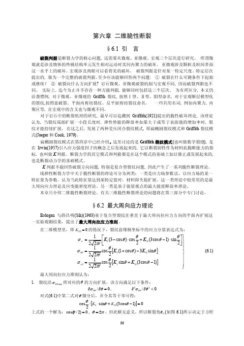
第六章 二维脆性断裂§6.1 引 言破裂判据是断裂力学的核心问题, 这需要从微观、亚微观、宏观三个层次进行研究。
所谓微观就是涉及物体的终极结构单元发生相对运动时其间内聚力的破坏。
亚微观涉及颗粒及粒间界面这一水平上的破坏。
宏观涉及肉眼可以看得见的破坏。
破裂判据是针对某一特定尺度、特定层次提出的, 做为一个完整的破裂判据,至少应该能够回答两个问题: ① 破裂在什么可测条件下起始或继续? ② 破裂向什么方向扩展? 岩石微观、亚微观破裂机制与宏观不同, 因而破裂判据也不同。
实际上, 迄今为止并不存在一种万能判据, 能够同时包括这三个层次。
为有所区分, 本文仍沿袭惯例, 对于微观、亚微观的 Griffth 裂纹, 按照Ⅰ型、Ⅱ型、Ⅲ型命名, 对于宏观断层模型化的裂纹,按照张破裂、平面内剪切裂纹、反平面剪切裂纹命名。
一些共用名词, 例如内聚力, 内聚区等, 在宏观中的含义也与微观不同。
对于岩石中的断裂机理的研究, 最早可以追溯到Griffith(1921)提出的脆性破坏理论, 该理论认为, 当裂纹端部扩展一小段长度时, 弹性势能的释放率如果大于或等于表面能的增加率时, 裂纹才能持续扩展。
在这之后, 发展了两种受压闭合裂纹模式, 即扁椭圆裂纹模式和Griffith 裂纹模式(Jaeger 和Cook, 1979)。
扁椭圆裂纹模式在第四章中已经介绍。
这里讨论的是Griffith 裂纹模式(也叫做数学裂缝), 是在Irwin(1957)引入应力强度因子的概念之后发展起来的, 它以断裂韧性作为材料抗脆断能力的指标, 也叫做K 判据。
断裂力学的其它模式和判据都是在这个模式的基础上加以修正或发展起来的, 也是断裂动力学的基础模式。
K 判据不能回答破裂方向问题, 特别是复合型裂纹问题, 因此产生了一系列脆性断裂理论。
线弹性断裂力学中关于脆性断裂的理论可分为两类:一类是应力场参数法,以应力场的某一特征量为参数。
第一章 绪论§1.1 断裂力学的概念任何一门科学都是应一定的需要而产生的,断裂力学也是如此。
一提到断裂,人们自然而然地就会联想到各种工程断裂事故。
在断裂力学产生之前,人们根据强度条件来设计构件,其基本思想就是保证构件的工作应力不超过材料的许用应力,即σ≤[σ]~安全设计安全设计对确保构件安全工作也确实起到了重大的作用,至今也仍然是必不可少的。
但是人们在长期的生产实践中,逐步认识到,在某些情况下,根据强度条件设计出的构件并不安全,断裂事故仍然不断发生,特别是高强度材料构件,焊接结构,处在低温或腐蚀环境中的结构等,断裂事故就更加频繁。
例如,1943~1947年二次世界大战期间,美国的5000余艘焊接船竟然连续发生了一千多起断裂事故,其中238艘完全毁坏。
1949年美国东俄亥俄州煤气公司的圆柱形液态天然气罐爆炸使周围很大一片街市变成了废墟。
五十年代初,美国北极星导弹固体燃料发动机壳体在试验时发生爆炸。
这些接连不断的工程断裂事故终于引起了人们的高度警觉。
特别值得注意的是,有些断裂事故竟然发生在σ<<[σ]的条件下,用传统的安全设计观点是无法解释的。
于是人们认识到了传统的设计思想是有缺欠的,并且开始寻求更合理的设计途径。
人们从大量的断裂事故分析中发现,断裂都是起源于构件中有缺陷的地方。
传统的设计思想把材料视为无缺陷的均匀连续体,而实际构件中总是存在着各种不同形式的缺陷。
因此实际材料的强度大大低于理论模型的强度。
断裂力学恰恰是为了弥补传统设计思想这一严重的缺陷而产生的。
因此,给断裂力学下的定义就是断裂力学是研究有裂纹(缺陷)构件断裂强度的一门学科。
或者说是研究含裂纹构件裂纹的平衡、扩展和失稳规律,以保证构件安全工作的一门科学。
断裂力学在航空、机械、化工、造船、交通和军工等领域里都有广泛的应用前景。
它能解决抗断设计、合理选材、制定适当的热处理制度和加工工艺、预测构件的疲劳寿命、制定合理的质量验收标准和检修制度以及防止断裂事故等多方面的问题,因此是一门具有高度实用价值的学科。


老司师多媒体教学系列断裂力学华中科技大学力学系司继文2009年11月10日老司师多媒体教学系列第六章断裂力学第六章能量法J裂纹扩展分析的能量方法是根据能量平衡原理来研究裂纹的扩展规律,并建立含裂纹构件的断裂条件的方法。
J它无需具体分析裂纹尖端附近的应力分布,只需§6-1能量释放率及其断裂判据设有一裂纹体,裂纹面积为A,裂纹失稳开裂前扩展了δA:载荷做功δW 体系弹性应变能变化δUe 塑性应变能变化δUp 裂纹表面能增加δΓ假定这一过程是绝热的和静态的,即不考虑热功间的交换。
能量守恒和转换定律——体系内能的增加等于外力功。
∴在裂纹扩展时:能量守恒和转换定律:∴裂纹扩展δA 时,弹性系统释放(耗散)的能量(势能):整个系统总势能在裂纹扩展时的变化等于外力的势能变化(等于外力做功的负值)与弹性应变能的变化之和。
J δU p 和δΓ为不可逆的,表示裂纹扩展δA 时所需要的塑性能和表面能,它们可视为裂纹扩展所要消耗的能量(阻止裂纹扩展的能量),因此要使裂纹扩展,系统必须提供能量。
e p W U U δδδδΓ=++U δΠδe p W U U δΠδδδδΓ−=−=+2.能量释放率GØG ——裂纹扩展单位面积弹性系统释放的能量。
Ø裂纹扩展单位面积所消耗的总势能。
它表示裂纹扩展单位面积时,提供给裂纹扩展所需的系统释放的能量(系统势能的减少)。
ØG 取决于裂纹体的载荷和几何形状。
ØG 的量纲:[力][长度]-1国际单位:N/m 工程单位:kg/mmØ按量纲分析,G 可看作是裂纹扩展单位长度所需的驱动力。
G 被形象地称为裂纹扩展力或裂纹驱动力。
e p3.裂纹扩展阻力∴能量平衡式变为:ØG c ——裂纹扩展单位面积所需要消耗的能量。
Ø它反映了材料抵抗断裂破坏的能力,由材料实验测定。
Ø裂纹扩展单位面积消耗于塑性变形及形成新表面的能量。
