东方马达04_5相步进马达组合 CSK 系列
- 格式:pdf
- 大小:4.06 MB
- 文档页数:19
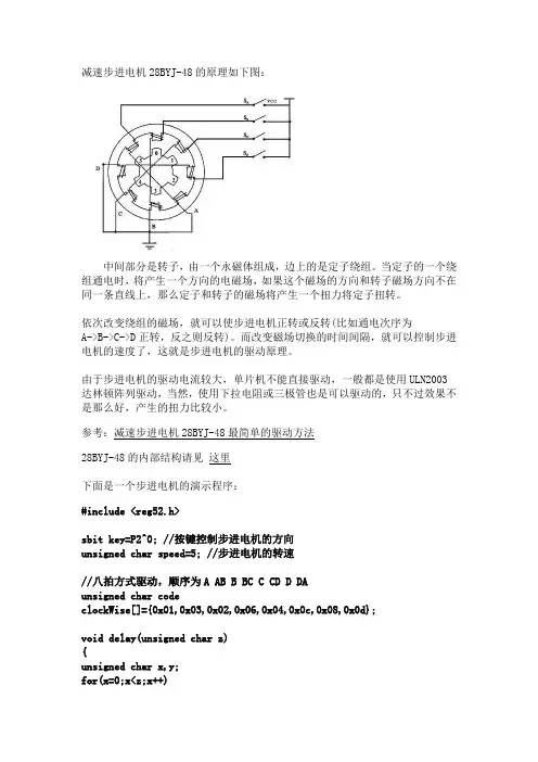
减速步进电机28BYJ-48的原理如下图:中间部分是转子,由一个永磁体组成,边上的是定子绕组。
当定子的一个绕组通电时,将产生一个方向的电磁场,如果这个磁场的方向和转子磁场方向不在同一条直线上,那么定子和转子的磁场将产生一个扭力将定子扭转。
依次改变绕组的磁场,就可以使步进电机正转或反转(比如通电次序为A->B->C->D正转,反之则反转)。
而改变磁场切换的时间间隔,就可以控制步进电机的速度了,这就是步进电机的驱动原理。
由于步进电机的驱动电流较大,单片机不能直接驱动,一般都是使用ULN2003达林顿阵列驱动,当然,使用下拉电阻或三极管也是可以驱动的,只不过效果不是那么好,产生的扭力比较小。
参考:减速步进电机28BYJ-48最简单的驱动方法28BYJ-48的内部结构请见这里下面是一个步进电机的演示程序:#include <reg52.h>sbit key=P2^0; //按键控制步进电机的方向unsigned char speed=5; //步进电机的转速//八拍方式驱动,顺序为A AB B BC C CD D DAunsigned char codeclockWise[]={0x01,0x03,0x02,0x06,0x04,0x0c,0x08,0x0d};void delay(unsigned char z){unsigned char x,y;for(x=0;x<z;x++)for(y=0;y<110;y++);}void main(){unsigned char i;while(1){for(i=0;i<8;i++){if(key) //按键未按下,正转{P0=clockWise[i];delay(speed);}else //按键按下,反转{P0=clockWise[8-i];delay(speed);}}}}Proteus仿真图及Keil源文件下载:/filebox/down/fc/79bf41133cc59eaf2ca9531a5382557 b/835705302/blog/item/7d9eb519397d7e1d34fa4148.html。
C-159
闭环电动机组合产品
AC 输入
高效率ARL
AC 输入
高效率AR
DC 输入
高效率AR
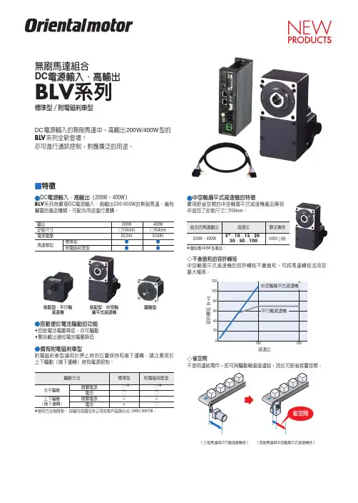
概要产品体系
2相步进电动机组合产品
DC 输入
CMK
步进电动机
高转矩
2相电动机PKP
2相电动机PK
5相电动机PK
选购配件
5相步进
电动机组合产品
AC 输入
RK
DC 输入
CRK
AC 输入
RK
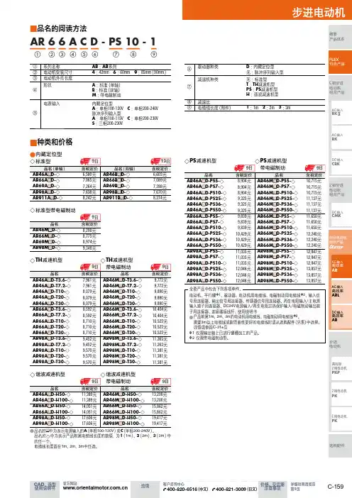
品名的阅读方法
■①
②⑧③⑦④⑥
⑤⑨
AR 6 6 A C D - PS 10 - 1
种类和价格
■
品名的 ●
■中为表示电源输入的A (单相100-120V )或C (单相200-240V )。
品名的◇中为表示产品附属电缆线长度的数值,为1(1m )、2(2m )、3(3m )中的任一个。
电缆线长度请在1m 、2m 、3m 中任选。
全套产品中包含下列各项单件。
电动机、平行键✽1、驱动器、电动机用电缆线、电磁制动用电缆线✽2、输入信号用连接器、输出信号用连接器、传感器信号用连接器、再生电阻输入/主电源输入端子用连接器、DC24V 电源输入/再生电阻过热保护输入/电磁制动输出端子用连接器、连接器接线杆、使用说明书
产品附属 ●1m 、2m 、3m 的电动机用电缆线、电磁制动用电缆线✽2。
需要3m 以上电缆线或耐弯曲性更好的电缆线时请从选购配件(另售)中选择。
详情请参阅C-318页
1 仅限输出轴上已进行键槽加工的产品。
✽
2 仅限带电磁制动型。
✽。
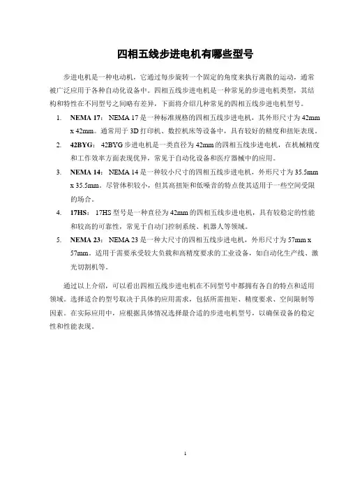
四相五线步进电机有哪些型号
步进电机是一种电动机,它通过每步旋转一个固定的角度来执行离散的运动,通常被广泛应用于各种自动化设备中。
四相五线步进电机是一种常见的步进电机类型,其结构和特性在不同型号之间略有差异,下面将介绍几种常见的四相五线步进电机型号。
1.NEMA 17: NEMA 17是一种标准规格的四相五线步进电机,其外形尺寸为42mm
x 42mm。
通常用于3D打印机、数控机床等设备中,具有较好的精度和扭矩表现。
2.42BYG: 42BYG步进电机是一类直径为42mm的四相五线步进电机,在机械精度
和工作效率方面表现优异,常见于自动化设备和医疗器械中的应用。
3.NEMA 14: NEMA 14是一种较小尺寸的四相五线步进电机,外形尺寸为35.5mm
x 35.5mm。
尽管体积较小,但其高扭矩和低噪音的特点使其适用于一些空间受限
的场合。
4.17HS: 17HS型号是一种直径为42mm的四相五线步进电机,具有较稳定的性能
和较高的可靠性,常见于自动门控制系统、机器人等领域。
5.NEMA 23: NEMA 23是一种大尺寸的四相五线步进电机,外形尺寸为57mm x
57mm。
适用于需要承受较大负载和高精度要求的工业设备,如自动化生产线、激光切割机等。
通过以上介绍,可以看出四相五线步进电机在不同型号中都拥有各自的特点和适用领域。
选择适合的型号取决于具体的应用需求,包括所需扭矩、精度要求、空间限制等因素。
在实际应用中,应根据具体情况选择最合适的步进电机型号,以确保设备的稳定性和性能表现。
1。

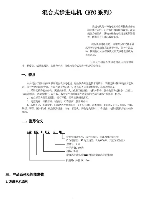
混合式步进电机(BYG系列)步进电机是一种将电脉冲信号转换成角位移的执行元件,可在宽广的范围内调速。
在负载能力范围内,其输出转角定位精度无积累误差,特别适合于开环数控系统。
混合式步进电机是一种兼有反应式和永磁式两种步进电机优点的新型电机,国外主流品种,国内也已大面积取代反应式步进电机成为市场热点。
五相及三相混合式步进电机因其分辨率小,精度高,低频无振荡,高频力矩大,而成为混合式步进电机中的佼佼者。
一、特点本公司自行研制的BYG系列混合式步进电机,结合国内外先进技术而设计,采用优质材料和精良工艺制造,实行严格的质量管理,在国内处于领先水平,可与国外同类电机媲美。
其显著特点是:1、采用优质冷轧高矽片,无机壳铆压,大大改善了磁性能;电机体积小,驱动电流和功耗小,力矩大,运行频率高,动态特性好,温升低。
本公司产品的静态及动态力矩较国内同类产品高出一档次。
2、有良好的内部阻尼特性,运行平稳,无明显低频振荡区。
3、造型美观,结构牢固,噪音低,可靠性高,使用寿命长。
4、品种齐全,系列完整,可满足各种使用场合。
正广泛应用于各类机床,切割机,轻工、印刷、包装、纺织、环保、医疗机械,航空航海设备,汽车,机器人,舞台灯光控制、广告设备,电脑绣花机等自动控制领域。
二、型号含义110 BYG 5 5 0 1 WB特殊型或派生号,以字母表示,无此项时为基本型(Z为增强型,WB为五边型,D为双轴伸,其它为派生型)规格号:1号转子齿数:50齿相数:5相混合式步进电机(FHB为方形混合式步进电机)机座号:外径φ110mm三、产品系列及性能参数1.方形电机系列2.圆形电机系列注:1、打 * 者为正在开发的新产品,可供期货;型号后有“Z”者为增强型。
2、二相电机为四引出线,四相电机为八引出线,除出线方式不同外,其余参数性能完全一样,配本公司驱动电源时用二相电机。
四相电机可改接成二相电机,有串联、并联及单极性三种接法,按并联接法时,相电流应加倍,四相电机用并联接法时,高速性能要优于其它接法。
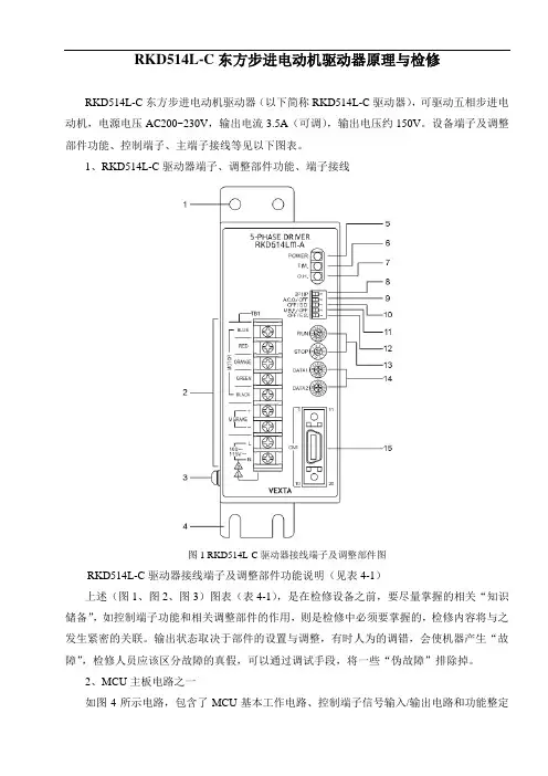
RKD514L-C东方步进电动机驱动器原理与检修RKD514L-C东方步进电动机驱动器(以下简称RKD514L-C驱动器),可驱动五相步进电动机,电源电压AC200~230V,输出电流3.5A(可调),输出电压约150V。
设备端子及调整部件功能、控制端子、主端子接线等见以下图表。
1、RKD514L-C驱动器端子、调整部件功能、端子接线图1 RKD514L-C驱动器接线端子及调整部件图RKD514L-C驱动器接线端子及调整部件功能说明(见表4-1)上述(图1、图2、图3)图表(表4-1),是在检修设备之前,要尽量掌握的相关“知识储备”,如控制端子功能和相关调整部件的作用,则是检修中必须要掌握的,检修内容将与之发生紧密的关联。
输出状态取决于部件的设置与调整,有时人为的调错,会使机器产生“故障”,检修人员应该区分故障的真假,可以通过调试手段,将一些“伪故障”排除掉。
2、MCU主板电路之一如图4所示电路,包含了MCU基本工作电路、控制端子信号输入/输出电路和功能整定电路。
〔MCU基本电路〕+5V电源,接入MCU的相关供电引脚;晶振元件XL101与振荡电路IC106、IC110生成的脉冲信号,做为时钟信号输入MCU的120脚;R184、D103、C136和IC108(HC14)内部两组反相器电路,组成上电复位电路,在CPU上电瞬间提供一个低电平的复位脉冲,输入MCU的122脚,使MCU内部计数器、寄存器清零。
以上电路提供MCU正常工作的基本条件。
〔控制端子信号输入/输出电路〕外部输入的4路控制信号经CN101插座进入。
高速光耦合器件PC101、表4-1 RKD514L-C驱动器接线端子及调整部件功能说明图2 RKD514L-C驱动器电源、步进电动机接线图PC102(TLP750)承担着对转速(脉冲)信号和正/反转控制信号的传输任务,输出信号再经两级反相器电路,输入至MCU的7、8脚。
这是两路基本控制信号;另两路控制信号经光耦合器PC103、PC104(P781)进行隔离传输,其中一路控制信号为调机信号ON/OFF指令,确定停车时马达处于直流刹车还是自由停车状态,两路信号输入至MCU的5、6脚。
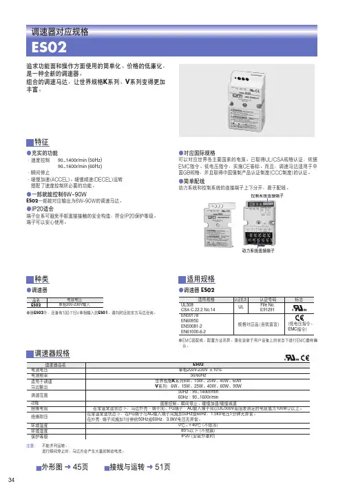
DS5C系列伺服驱动器用户手册无锡信捷电气股份有限公司信捷电气DS5C系列伺服驱动器用户手册第一版安全注意事项目录————————————————伺服系统的选型————————————————伺服驱动器及电机安装————————————————伺服驱动器及电机接线————————————————伺服系统使用前操作————————————————EtherCAT总线通讯————————————————EtherCAT总线控制模式————————————————对象字典详细说明————————————————伺服增益的调整————————————————报警分析————————————————通讯案例————————————————附录————————————————手册更新日志————————————————12345678910基本说明●感谢您购买了信捷DS5C系列伺服驱动产品。
●本手册主要介绍DS5C系列伺服驱动器、MS5/6系列伺服电机的产品信息。
●在使用产品之前,请仔细阅读本手册,并在充分理解手册内容的前提下,进行接线。
●请将本手册交付给最终用户。
本手册适合下列使用者参考●伺服系统设计者●安装及配线工作者●试运行及伺服调试工作者●维护及检查工作者手册的获取途径●印刷版手册请向购买产品的供应商、代理商、办事处咨询索取。
●电子版手册登陆信捷官方网站下载。
责任申明●手册中的内容虽然已经过仔细的核对,但差错难免,我们不能保证完全一致。
●我们会经常检查手册中的内容,并在后续版本中进行更正,欢迎提出宝贵意见。
●手册中所介绍的内容,如有变动,请谅解不另行通知。
联系方式如果您有任何关于本产品的使用问题,请与购买产品的代理商、办事处联系,也可以直接与信捷公司联系。
●电话:400-885-0136●传真:*************●地址:无锡市滴翠路100号创意产业园7号楼4楼●邮编:214072WUXI XINJE ELECTRIC CO., LTD. 版权所有未经明确的书面许可,不得复制、传翻或使用本资料及其中的内容,违者要对造成的损失承担责任。
科尔摩根模块化直接驱动旋转电机选型指南带有AKD系列伺服驱动系统科尔摩根:您在运动控制领域的最佳合作伙伴在设计每一个解决方案之前,我们都会深入了解机器设计者和用户所面临的困难。
目录◆ 直接驱动电机概述 4◆ 模块化直接驱动旋转® (DDR) 电机 6◆ 冲床给料设备应用 9◆ 系统概述 10 C(H)04x, C(H)05x, C(H)06x, C(H)09x, C(H)13x◆ 性能数据 12 C(H)04x, C(H)05x, C(H)06x, C(H)09x, C(H)13x◆ 外形图 28 C(H)04x, C(H)05x, C(H)06x, C(H)09x, C(H)13x◆ 安装要求 36 C(H)04x, C(H)05x, C(H)06x, C(H)09x, C(H)13x◆ 模块化DDR ®的连接器引脚分配 38◆ 模块化DDR ®到AKD 系列电缆 39◆ 模块化DDR ®的型号命名 40◆ AKD 系列伺服驱动器 42 AKD ®2G 伺服驱动器 AKD ®伺服驱动器◆ AKD 系列伺服驱动器的型号命名 52◆ 科尔摩根解决方案 55 自动化和运动控制 自助工具科尔摩根模块化直接驱动旋转电机选型指南克服设计、采购和时间障碍科尔摩根深知:如果能帮助原始设备制造商的工程师清除各种障碍,就可以显著提高其工作效率。
因而,我们主要通过如下三种方式来帮助他们:集成标准和定制化产品在很多情况下,最佳方案都不是一成不变的。
我们拥有专业应用知识,可以根据全面的产品组合来修改标准产品或开发完全定制化的解决方案,从而为设计奠定良好的 基础。
不仅提供部件,而且提供运动控制解决方案随着企业逐渐缩减供应商数量并精简工程设计团队,他们需要能提供广泛集成解决方案的全系统供应商。
科尔摩根可以提供完整的解决方案以及运动子系统,并将编程软件、工程设计服务以及一流的运动组件有机结合在一起。
东方马达软件使用说明东方马达软件使用说明1.软件简介东方马达软件是一款为东方马达公司开发的专用软件,旨在帮助用户更好地管理和控制马达产品。
本使用说明将详细介绍软件的安装、配置、使用方法等内容,以帮助用户快速上手。
2.环境要求- 操作系统:Windows 7及以上版本- 内存.4GB及以上- 硬盘空间.100MB及以上3.安装3.1 软件安装包从东方马达官方网站上最新的软件安装包。
3.2 安装软件双击安装包文件,按照安装向导的提示完成软件的安装过程。
4.配置4.1 设置连接打开软件主界面,在设置菜单中选择连接设置,输入正确的马达控制器IP地质和端口号,保存。
确保软件与设备连接正常。
4.2 马达参数配置在配置菜单中选择马达参数配置,根据实际需求设置马达参数,包括电流限制、速度限制、加速度等。
5.软件功能介绍5.1 马达状态监控软件提供实时监控马达状态的功能,包括当前速度、转向、电流等信息。
用户可以通过监控界面快速了解马达的运行情况。
5.2 马达控制用户可以通过软件对马达进行控制,包括启动、停止、改变转向等操作。
操作简单方便。
5.3 马达性能分析软件提供马达性能分析功能,用户可以通过该功能对马达的工作情况进行详细分析,包括电流波形、速度曲线等。
6.常见问题解答以下是一些常见问题及解答:Q: 软件无法连接到马达控制器怎么办?A: 请检查马达控制器的IP地质和端口号是否配置正确,以及网络连接是否正常。
Q: 马达运行过程中出现异常情况怎么处理?A: 首先检查马达参数配置是否合理,如电流限制、速度限制等,根据具体情况进行调整。
若问题依然存在,请联系我们的技术支持人员。
7.附件本文档涉及的附件包括:软件安装包、马达参数配置文件等。
8.法律名词及注释- IP地质:Internet协议地质的缩写,用于唯一标识网络中的设备。
- 端口号:网络通信中的逻辑端口,用于标识一个特定的网络进程或应用程序。
*HP-P025*HP-P025-15-phase stepping motor unitCRK Series Built-in Controller(Stored Program) InformationThank you for purchasing an Oriental Motor product.Introduction⏹ Before useOnly qualified personnel should work with the product. Use the product correctly after thoroughly reading the section “Safety precautions”.The product described in this manual has been designed and manufactured for use in general industrial machinery, and must not be used for any other purpose. For the driver’s power supply, use a DC power supply with reinforced insulation on its primary and secondary sides.Oriental Motor Co., Ltd. is not responsible for any damage caused through failure to observe this warning.⏹ Overview of the productThe CRK series built-in controller (Stored program) is a unit product consisting of a 5-phase stepping motor driver with built-in controller function and a 5-phase stepping motor offering high torque with low vibration. The driver supports I/O control and RS-485 communication.Set the operating data and parameters using RS-485 communication.⏹ Hazardous substancesRoHS (Directive 2002/95/EC 27Jan.2003) compliant⏹ Checking the productVerify that the items listed below are included. Report any missing or damaged items to the branch or sales office from which you purchased the product.∙ Motor………………………………………………………………………..…..1 pc. ∙ Driver………………………………………………………………………..…..1 pc. ∙ CN1 Power supply connector (3 terminals)…….…………………….…….1 pc. ∙ CN2 I/O ribbon cable/connector assembly [1 m (3.3 ft.)]………......……..1 pc. ∙ CN4 lead wire/connector assembly (5 leads) [0.6 m (2 ft.)]……….….…..1 pc. ∙ CN5 encoder lead wire/connector assembly (9 leads) [0.6m (2 ft.)]…..... 1 pc. (Encoder Motor/Driver models only)∙ Information (this document)……………………………………………..……1 copy ∙ Motor lead wire/connector assembly (5 leads) [0.6 m (2 ft.)]…….….….. 1 pc. (High torque and High Resolution type motors only)∙ Encoder motor lead wire/connector assembly [0.6m (2 ft.)] ……………..1 pc. (Encoder motors only)∙ Software manual (HP-P024) is available for download for free at: /support/operator_manuals.htm .An optional Immediate Motion Creator (IMC) Graphical User Interface (GUI) isavailable for downlad for free at:/support/software/software.html⏹Names and functions of parts ● MotorIllustration shows the PK56☐ standard type.● Front of the driverName DescriptionPOWER LED (green) This LED is lit while the main power is input. ALARM LED (red) This LED will blink when an alarm generates (aprotective function is triggered). You can check the generated alarm by counting the number of times the LED blinks.C-DAT LED (green) This LED will blink or illuminate steadily when thedriver is communicating with the master station properly via RS-485 communication.C-ERR LED (red) This LED will illuminate when a RS-485communication error occurs with the master station.Address number setting switch (SW1) Set the address number for RS-485communication.Function setting switches (SW2) No.1 to 3: Set the baud rate for RS-485communication.No.4: Set device to single or multi axis modePower supply connector (CN1) Connection for the main power supply (+24 VDC) I/O signals connector (CN2) Connection for the I/O signals. Unused connector (CN3) Not Used Motor connector (CN4) Connection for the motor. Encoder connector (CN5) Connection for the encoder.● Top of the driverName Description Termination resistor setting switch (SW3) Set the termination resistor (120 Ω) for RS-485 communication. RS-485 communication connector (CN6/CN7) Connect the RS-485 communication cable. (Not Supplied)⏹ Location for installationThe driver is designed and manufactured for installation in equipment.Install it in a well-ventilated location that provides easy access for inspection. The location must also satisfy the following conditions:∙ Inside an enclosure that is installed indoors (provide vent holes) ∙ Operating ambient temperatureMotor: -10 to +50 °C (+14 to +122 °F) (non-freezing) Driver: 0 to +40 °C (+32 to +104 °F) (non-freezing)∙ Operating ambient humidity 85% or less (non-condensing)∙ Area that is free of explosive atmosphere or toxic gas (such as sulfuric gas) or liquid∙ Area not exposed to direct sun∙ Area free of excessive amount of dust, iron particles or the like∙ Area not subject to splashing water (rain, water droplets), oil (oil droplets) or other liquids∙ Area free of excessive salt∙ Area not subject to continuous vibration or excessive shocks∙ Area free of excessive electromagnetic noise (from welders, power machinery, etc.)∙ Area free of radioactive materials, magnetic fields or vacuum⏹ Installing the motorThe motor can be installed in any direction. Install the motor onto an appropriate flat metal plate having excellent vibration resistance and heat conductivity.When installing the motor, secure it with four bolts (not supplied) through the four mounting holes. Do not leave a gap between the motor and metal plate.Insert the pilot located on the motor's installation surface into themounting plate's pilot hole.Installation method AInstallation method BScrew size, tightening torque and installation methodMotor type (with or without Encoder)Frame size [mm (in.)] Nominal sizeTightening torque [N·m (oz-in)] Effectivedepth of bolt[mm (in.)]Installationmethod20 (0.79) M2 0.25 (35.4)28 (1.10) M2.5 0.5 (70.8)2.5 (0098 42 (1.65) M3 1 (142) 4.5 (0.177) A Standard, High resolution,High Torque60 (2.36) M4 2 (280) − B 28 (1.10) M2.5 0.5 (70.8) 4 (0.157) TH geared42 (1.65) 60 (2.36) M4 2 (280) 8 (0.315)A 28 (1.10) M3 1 (142) 6 (0.236)42 (1.65) M4 2 (280) 8 (0.315)PS geared 60 (2.36) M5 2.5 (350) 10 (0.394) A 20 (0.79) M2 0.25 (35.4) 5 (0.2)42 (1.65) M4 2 (280) 8 (0.315)Harmonicgeared60 (2.36)M5 2.5 (350) 10 (0.394) A ⏹ Permissible overhung load and permissible thrust loadThe overhung load on the motor’s output shaft or gear output shaft must be keptwithin the permissible values for each part number. The thrust load must notexceed the motor’s mass. Please visit our website, , formore specific information for each motor type. Installing the driver ● Installation direction Use a DIN rail 35 mm (1.38 in.) wide to mount the driver. Provide 50 mm (1.97 in.) clearances in the horizontal and vertical directions between the driver and enclosure or other equipment within the enclosure.Push up the driver’s DIN lever until it locks. Hang the hook at the rear to the DIN Removing from DIN railPull the DIN lever down until it locks using a flat tip screwdriver, and lift the bottom of theLower ribbon cable Lead wire color Pin No. Signal name Description Brown-3 B1 MOVE+Red-3 B2 MOVE − Motor Moving outputOrange-3 B3 ALM+Yellow-3 B4 ALM − Alarm outputGreen-3 B5 OUT1+Blue-3 B6 OUT1− General output 1 *Purple-3 B7 OUT2+Gray-3 B8 OUT2− General output 2 *White-3 B9 OUT3+Black-3 B10 OUT3− General output 3 *Brown-4 B11 OUT4+Red-4 B12 OUT4− General output 4 *Orange-4 B13 N.C. Not used Yellow-4 B14 N.C. Not used Green-4 B15 PLS-OUT+Blue-4 B16 PLS-OUT − Pulse output (Line driver output)Purple-4 B17 DIR-OUT+Gray-4 B18 DIR-OUT − Direction output (Line driver output)White-4 B19 GND GND Black-4 B20 N.C. Not used* The function of General Output 1(Out1) to 4(Out4) can be assigned unique functions using the “OUTxxx” commands.⏹ CN4: Motor connectorConnect the motor using the supplied CN4 leadwire/connector assembly (5 leads).Pin No. Name Description1 BLUE Blue motor lead2 REDRed motor lead 3 ORANGE Orange motor lead 4 GREEN Green motor lead 5 BLACK Black motor lead⏹ CN5: Encoder connectorIf an encoder is to be used, connect the encoder using the supplied CN5 leadwire/connector assembly (9 leads).Pin No. Signal name Lead wire colorDescription 1 ENC-A+ Red 2 ENC-A −BrownEncoder input A-channel(Line receiver) 3 ENC-B+ Green 4 ENC-B − BlueEncoder input B- channel(Line receiver) 5 ENC-I + Yellow6 ENC-I − OrangeEncoder input I ndex signal (Line receiver) 7 +5 VDC OUT White+5 VDC power supply output forencoder8 GND Black GND 9 SHIELD PurpleShield (connect to GND)⏹ CN6/7: RS-485 communication connectorUse these connectors to connect to RS-485 communication.Pin No. Signal name Description1 N.C. Not used2 GND GND3 TR+RS-485 communication signal (+) 4 N.C. Not used 5 N.C. Not used6 TR −RS-485 communication signal (−) 7 N.C. Not used 8 N.C. Not usedBe sure to turn off the driver power before setting the switches. If theswitches are set while the power is still on, the new switch settings will not become effective until the driver power is cycled.⏹ Address numberSet the address number using the address setting switch (SW1). Factory setting:SW1: 0, (address number 0)⏹ Multi-axis modeSet the to device to multi-axis mode using the multi-axis mode setting switch (SW2-No.4) to ON. Factory setting:SW2-No.4: OFF, (single axis mode)Address number SW10 0 1 1 2 2 3 3 4 4 5 5 6 6 7 7 8 8 9 9 10 A 11 B 12 C 13 D 14 E 15 F⏹ Baud rateSet the baud rate using Nos. 1 to 3 of the function setting switch (SW2). Factory setting: All OFF (9600 bps)Baud rate (bps) SW2-No.3 SW2-No.2 SW2-No.19600 OFF OFF OFF 19200 OFF OFF ON 38400 OFF ON OFF 57600 OFF ON ON 115,200 ON OFF OFF 115,200 ON OFF ON 115,200 ON ON OFF 115,200 ON ON ON⏹ Termination resistorSet the termination resistor forRS-485 communication (120 Ω) using the termination resistor setting switch (SW3).Factory setting:OFF (termination resistor disabled)SW3 Termination resistor (120 Ω)OFF Disabled ON EnabledThe precautions described below are intended to prevent danger or injury to the user and other personnel through safe, correct use of the product. Use the product only after carefully reading and fully understanding these instructions.Handling the product without observing the instructions that accompany a“Warning” symbol may result in serious injury or death.General∙ Do not use the product in explosive or corrosive environments, in the presence of flammable gases, locations subjected to splashing water, or near combustibles. Doing so may result in fire, electric shock or injury.∙ Assign qualified personnel the task of installing, wiring, operating/controlling, inspecting and troubleshooting the product. Failure to do so may result in fire, electric shock or injury.∙ The motor will lose its holding torque when the power supply or motorexcitation turned off. If this product is used in a vertical application, be sure to provide a measure for the position retention of moving parts. Failure to provide such a measure may cause the moving parts to fall, resulting in injury or damage to the equipment.∙ With certain types of alarms (protective functions), the motor may stop when the alarm generates and the holding torque will be lost as a result. This will result in injury or damage to equipment.∙ When an alarm is generated, first remove the cause and then clear the alarm. Continuing the operation without removing the cause of the problem may cause malfunction of the motor and driver, leading to injury or damage to equipment.∙ Connection∙ Keep the driver’s input-power voltage within the specified range to avoid fire. ∙ For the driver's power supply, use a DC power supply with reinforcedinsulation on its primary and secondary sides. Failure to do so may result in electric shock.∙ Connect the cables securely according to the wiring diagram in order to prevent fire.∙ Do not forcibly bend, pull or pinch the power supply cable and motor cable. Doing so may cause a fire. This will cause stress to the connecting section and may result in damage to equipment.Operation∙ Turn off the driver power in the event of a power failure, or the motor maysuddenly start when the power is restored and may cause injury or damage to equipment.∙ Do not turn the excitation to off while the motor is operating. The motor will stop and lose its holding ability, which may result in injury or damage to equipment.∙ Configure an interlock circuit using a sequence program so that when aRS-485 communication error occurs, the entire system including the driver will operate safely.Repair, disassembly and modification∙ Do not disassemble or modify the motor and driver. This may cause injury. Refer all such internal inspections and repairs to the branch or sales office from which you purchased the product.Handling the product without observing the instructions that accompany a “Caution” symbol may result in injury or property damage.General∙ Do not use the motor and driver beyond its specifications, or injury or damage to equipment may result.∙ Keep your fingers and objects out of the openings in the motor and driver, or fire or injury may result.∙ Do not touch the motor and driver during operation or immediately after stopping. The surface is hot and may cause a skin burn(s).Transportation∙ Do not hold the motor output shaft or motor cable. This may cause injury.Installation∙ Install the motor and driver in the enclosure in order to prevent injury.∙ Keep the area around the motor and driver free of combustible materials in order to prevent fire or a skin burn(s).∙ Provide a cover over the rotating parts (output shaft) of the motor to prevent injury.Operation∙ Use a motor and driver only in the specified combination. An incorrect combination may cause a fire.∙ Provide an emergency stop device or emergency stop circuit external to the equipment so that the entire equipment will operate safely in the event of a system failure or malfunction. Failure to do so may result in injury.∙ Before supplying power to the driver, turn all control input to the driver to OFF. Otherwise, the motor may start suddenly at power ON and cause injury or damage to equipment.∙ Set the speed and acceleration/deceleration rate at reasonable levels. Otherwise, the motor will misstep and the moving part may move in an unexpected direction, resulting in injury or damage to equipment.∙ Do not touch the rotating part (output shaft) during operation. This may cause injury.∙Before moving the motor directly with the hands, confirm that the power supply or motor excitation turned off and motor current is cut off. Failure not to do so may result in injury.∙ The motor surface temperature may exceed 70 °C (158 °F) even under normal operating conditions. If the operator isallowed to approach the running motor, attach a warninglabel as shown below in a conspicuous position. Failure to do so may result in skin burn(s).Warning label∙ Immediately when trouble has occurred, stop running and turn off the driver power. Failure to do so may result in fire or injury.∙ Static electricity may cause the driver to malfunction or suffer damage. While the driver is receiving power, do not touch the driver. Use only an insulated screwdriver to adjust the driver's switches.Disposal∙ To dispose of the motor and driver, disassemble it into parts and components as much as possible and dispose of individual parts/components as industrialwaste. If you have any question, contact your nearest Oriental Motor branch or sales office.∙ Unauthorized reproduction or copying of all or part of this manual is prohibited.∙ Oriental Motor shall not be liable whatsoever for any problems relating to industrial property rights arising from use of any information, circuit, equipment or device provided or referenced in this manual.∙ Characteristics, specifications and dimensions are subject to change without notice.∙ While we make every effort to offer accurate information in the manual, we welcome your input. Should you find unclear descriptions, errors or omissions, please contact the nearest sales office. ∙is a registered trademark or trademark of Oriental Motor Co., Ltd., in Japan and other countries.© Copyright ORIENTAL MOTOR USA CORP., 2011。