电子显微镜使用说明书..
- 格式:doc
- 大小:2.25 MB
- 文档页数:14

电子显微镜使用说明书一、前言欢迎使用本产品,本使用说明书详细介绍了电子显微镜的使用方法和相关注意事项。
为了确保您能得到更好的使用体验,请仔细阅读本说明书并按照指导进行操作。
二、产品概述电子显微镜(SEM)是一种利用电子束对样品进行成像的高分辨率显微镜。
本产品采用先进的电子光学系统和图像处理技术,可以提供清晰、详细的样品表面形貌信息。
电子显微镜广泛应用于材料科学、生命科学、纳米科技等领域。
三、安全注意事项1. 在使用电子显微镜之前,确保工作环境清洁整洁,并远离尘埃和化学品等污染物。
2. 请确保设备接地,以降低静电的影响。
3. 使用过程中,请保持镜头干燥,避免接触水、油等物质。
4. 请勿在未经许可的情况下拆解设备,以免导致损坏和人身伤害。
四、操作步骤1. 预热:a. 打开电子显微镜主机电源,并等待预热完成。
b. 启动计算机,确保与电子显微镜连接正常。
2. 系统检查:a. 检查电子显微镜的各个部件是否正常运作。
b. 检查电子束发射系统,确保电子束发射情况正常。
c. 检查检测系统,确保接收到的电子信号正常。
3. 样品准备:a. 准备样品,并确保其表面干净,不受污染。
b. 将样品固定在样品台上,并使用导电性粘贴剂固定。
4. 图像获取:a. 调整加速电压和聚焦等参数,以获得最佳成像效果。
b. 将样品台移动至显微镜下方的位置,并确保样品台与显微镜接触良好。
c. 点击软件界面上的图像获取按钮,开始采集样品的显微图像。
5. 数据处理:a. 显示图像后,可以使用软件提供的图像处理功能进行亮度、对比度、锐化等调整。
b. 可以进行测量、标记、拍摄和保存等操作,以满足实验需求。
六、维护保养1. 使用完毕后,关闭电子显微镜主机和计算机。
2. 清洁镜头时,使用专用清洁棉和无纺布,轻轻擦拭,避免使用有机溶剂和刷子清洗。
3. 定期检查设备的连接线是否松动,如有松动请及时处理。
4. 若设备长时间不使用,请将其存放在洁净、干燥的环境中,并避免受潮、受热和受潮。

电子显微镜操作步骤说明书简介:电子显微镜(Electron Microscope,简称EM)是一种利用电子束来观察和研究物质的高分辨率显微技术。
本文将详细介绍电子显微镜的操作步骤,以帮助读者正确操作并获得准确的实验结果。
操作步骤:1. 准备工作在使用电子显微镜之前,需要进行一些准备工作。
首先,确保实验室环境干净,无尘、无污物,以确保获得清晰的显微图像。
其次,将样本制备好,确保样本表面平整、无污染,并且大小适宜,方便放置于电子显微镜观察。
2. 开机与预热将电子显微镜接通电源,确保连接无误。
然后,打开电子显微镜主机的电源开关,待其启动完成后,进行预热。
预热时间根据具体仪器而有所不同,请根据仪器使用说明书确定预热时间。
在预热过程中,可以进行一些其他准备工作,如调整目镜和物镜的位置。
3. 调整仪器参数在预热完成后,进入仪器调整阶段。
首先,调整加速电压和透射电镜电压。
加速电压决定了电子束的能量,透射电镜电压决定了样本投射到屏幕上的亮度和对比度。
根据实验要求,选择合适的加速电压和透射电镜电压。
4. 样本装载将已经准备好的样本装入样本架,并通过样本架的旋转或移动机构将样本调整到适当的位置。
确保样本安装稳固,并注意不要触碰样本的表面。
5. 调整焦距与对焦通过调整物镜的焦距和目镜的焦距,可以实现对样本的清晰观察。
首先,通过移动物镜或调整物镜焦距的方式来对焦。
然后,通过调整目镜的焦距,使样本的图像清晰可见。
在对焦过程中,可以通过透射电镜和屏幕上的图像实时观察和调整。
6. 选择增大倍率与观察根据需要,选择合适的增大倍率。
电子显微镜具有较高的放大倍率,可以观察微小的物体和细节。
在观察过程中,可以通过样本架的调整,以及调节图像亮度和对比度,来获得最佳的观察效果。
7. 实时调整参数与记录结果在观察样本的过程中,可能需要对加速电压、透射电镜电压、焦距等参数进行实时调整,以获得更好的观察效果。
同时,将观察到的结果记录下来,以备后续分析和研究使用。
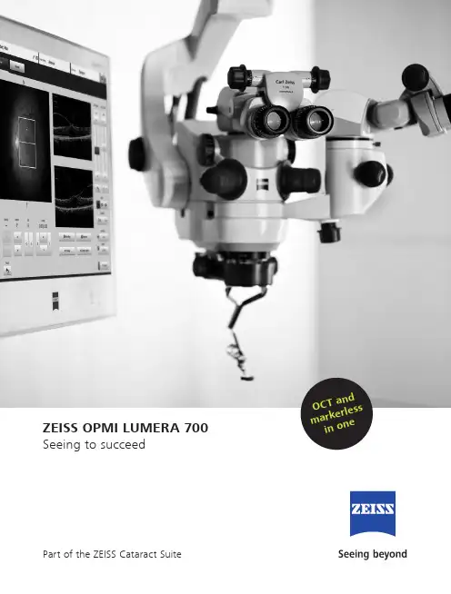
ZEISS OPMI LUMERA 700 Seeing to succeedPart of the ZEISS Cataract Suite O C T an d m a r ke r l e s si n o neSeeing to succeed. ZEISS OPMI LUMERA 7002What drives a surgeon? A commitment to preservingand restoring patients’ sight – to saving vision.We share your dedication.One example is with the OPMI LUMERA® 700 from ZEISS, an operating microscope ideally suited for every ophthalmic surgery speciality. Experience markerless IOL alignment and integrated intraoperative OCT* imaging – all in one device. ZEISS OPMI LUMERA 700 – our commitmentto helping you see to succeed.3*ZEISS RESCAN 7004With ZEISS CALLISTO eye markerless alignment,manual marking steps can be skipped altogether foran efficient and precise* toric IOL alignmentto reduce residual astigmatism.For cataract surgeries, ZEISS OPMI LUMERA 700,with its well-known patented SCI illumination,ZEISS optics and CALLISTO eye ® from ZEISS, provides thebest anterior views and precise* assistance functions.Seeing to succeed in cataract surgeryPrecise* and efficient** markerless toric IOL alignmentI save 6 minutes per patient and improve alignment precision by 40% compared to manual marking.Wolfgang Mayer, MD, Augenklinik der Universität München, Germany »»Part of theZEISS Cataract SuiteConnecting theCataract Workflow* V IROS research team of Prof. Findl: Clinical data of Dr. Varsits "Deviation between the postoperative (at the end of surgery in the operating room) and aimed IOL axes was 0.52 degrees± 0.56 (SD)" published in J Cataract Refract Surg 2019; 45:1234–1238 and Clinical data of Dr. Hirnschall presented at ESCRS 2013.** C linical data of Dr. Mayer: "Toric IOL implantation was significantly faster using digital marking" published in J Cataract Refract Surg 2017; 43:1281–1286.5Cataract assistance functions for every step of the surgeryThe assistance functions of ZEISS CALLISTO eye are completely surgeon-controlled – with either the foot control panel or handgrips.CALLISTO eye informationOPMI LUMERA 700 parametersEfficient markerless IOL alignmentStarting with a biometry referenceimage from the IOLMaster ® from ZEISS,data is transferred smoothly to ZEISSCALLISTO eye. This data is used to createoverlays in the eyepiece. Save time,increase efficiency and reduce residualastigmatism when you:• skip manual preoperative marking• skip manual data transfer• skip manual intraoperative marking Efficient surgery setup The image quality check supports you to optimize light intensity, magnification and centration of the microscope to efficiently set up the reference axis. The well-proven* eye tracking automatically compensates for eye movements and supports the use of the assistance functions.» C ALLISTO eye enabled easy and exacttoric IOL alignment in all cases.«Prof. Findl,VIROS, Hanusch Hospital, Vienna, AustriaLRI Perform limbal relaxing incisionsZ ALIGN ®Perform toric IOL centration on the visualaxis provided by the ZEISS IOLMaster andperform rotational alignment Incision Position incisions, optionally on the steep axis; add opposite clear cornea incision and paracentesesRhexis Precisely* size and shape capsulorhexisand align the IOL on the visual axisprovided by the ZEISS IOLMasterSeeing to succeed in glaucoma surgery Improved visualizationAs minimally invasive glaucoma surgery (MIGS) and canaloplasty procedures evolve, intraoperative OCT plays an increasingly important role in difficult to see spaces. The integrated intraoperative OCT* images of the ZEISS OPMI LUMERA 700 aids the visualization of the device placement.6*ZEISS RESCAN 700More information to supportyour decisions during surgery Integrated intraoperative OCT*allows visualization of orientationand placement of the MIGS implant. Intraoperative OCT* images enable physicians to visualize detailed structures in the natural physiological shape.Stay focused on thearea of interestSave time by maintaining the selected intraoperative OCT* scan locationwith the new automatic XY tracker. In addition to the proven Z tracker, the XY tracker compensates for movements of the eye or the microscope.Protect the retinaShield the retina from excessive light exposure with the integrated retina protection filter.Flexible perspective fora better viewTilt the microscope head as needed to better observe the iridocorneal angle.Intraoperative OCT gives me better control in modern glaucoma surgery through visualization of MIGS and canaloplasty.Hagen Thieme, MD, Otto-von-Guericke-Universität Magdeburg, GermanyVerify the position and function of innovative glaucoma drainage devices (e.g. stents)*ZEISS RESCAN 70078Seeing to succeed in cornea surgeryReduce graft manipulationA presentation of Dr. Alain Saad, et al, clinical data wasshown at AAO 2015 comparing severe corneal edema casesof 13 eyes supported by intraoperative OCT* (ZEISS) and 15without. The conclusion showed that there was reduced cellloss using intraoperative OCT*. Literature has shown thatZEISS intraoperative OCT* can provide valuable anatomicalinformation and help with surgical decision making**.The integrated intraoperative OCT* of the ZEISS OPMI LUMERA 700 visualizes the actual physiological shape of the cornea intwo different scan views. Switch between views with a touch of the finger or tap of the foot to make your decisions faster.Make faster decisions with two scan depths and a realistic view.Quickly change between high-resolution OCT scans (2.9 mm scan depth in tissue) and large overview images (5.8 mm scan depth in tissue) to visualize and assess graft orientation.Observe the natural physiological shape of the cornea with distortion-free intraoperative OCT* images. See how intuitive OCT image navigation is duringsurgery.OCT* image of graft orientation during DMEK surgery in the ocularSee the graft orientation without manipulation in DMEK surgery with intraoperative OCT*ZEISS RESCAN 700DMEK: save time with easygraft monitoringMonitor the graft orientation andassess the interface with the patient´scornea. Verify proper graft positioning as well as visualize fluid interface and graft adherence.DALK: secure big-bubble procedure OCT* imaging helps the surgeon during DALK to assess the dissection depthin order to reduce perforation risk and9** C linical data of Cost B, Goshe JM, Srivastava S, Ehlers JP published in Am J Ophthalmol. 2015 Sep; Intraoperative optical coherence tomography-assisted descemet membrane endothelial keratoplasty in the DISCOVER study.***Not available in combination with intraoperative OCT.I reduced graft manipulation time by 4.2 minutes during DMEK.*Alain A. Saad, MD, Fondation Rothschild, Paris, France»»potentially improve the reproducibilityof the big-bubble procedure.Full integration forincreased efficiencyThe integrated slit illuminator***provides four slit widths with left-rightslit movement to simplify observation ofthe cornea and anterior chamber –withoutthe hassle of fitting extra accessories.*ZEISS RESCAN 70010Seeing to succeed in retina surgery Make more informed decisionsSuperb OCT images forinformed decisionsIntegrated intraoperative OCT* addsa real-time third dimension tovisualization capabilities for viewingtransparent structures of the eyeduring surgery.Monitor the surgical progress and makedecisions accordingly. The superb clarityof the intraoperative OCT* images canprovide unexpected insights, allowingstrategy adjustments during surgery.With innovative technologies such as integrated intraoperative OCT* and the non-contact fundus viewing system RESIGHT ® 700 from ZEISS, the ZEISS OPMI LUMERA 700 gives new meaning to “insight” when performing retina surgery procedures.Intraoperative OCT* revealed undetected macular holes after peeling in 10% of highly myopic eyes.Ramin Tadayoni, MD, PhD, University of Paris VII, Sorbonne Paris Cité, Paris, France »»*ZEISS RESCAN 70011Keep your focusThe new automatic XY tracker, in addition to the proven Z tracker, compensates for movements of the eye or the microscope, saving time by maintaining the selected intraoperative OCT* scan plete your surgery with confidenceVerify that all necessary membrane residue has been completely removed following ILM peelings with OCT* imaging. Detect macular holes that might easily be overlooked and monitor vitreomacular traction.128D wide-field lensFor peripheral visualization and a clear overview during vitrectomy60D macular lensFor high magnification of the maculaSee the retina in more detail The proven non-contact retina visualization system ZEISS RESIGHT 700provides a clear, detailed view of the retina. Varioscope optics from ZEISS enable surgeons to stay fully focused on the area of interest. Switch magnification quickly with the two aspheric lenses. It is also possible to use a direct or indirect contact glass.With the ZEISS RESIGHT 700, the surgical microscope automatically adjusts the camera settings, Invertertube E settings, lighting and speed of motion to the preset values for retina surgery.*ZEISS RESCAN 70012Seeing to succeed in teaching Share your knowledge• Integrated intraoperative OCT* that provides a clearer image of what is happening during surgery• Integrated assistant scope with independent magnification, which can be linked to the main microscope for teaching purposes • ZEISS CALLISTO eye cockpit to observe and share informationZEISS OPMI LUMERA 700 features excellent tools for enhancing the learning experience. Students need to see every detail to have a clear understanding of the surgical process. Whether during surgery, viewing through the assistant scope orreviewing post-surgery, it is important to provide images with excellent contrast, color, and high resolution.The optical performance from ZEISS enables students to see deep into the ophthalmic world using:More documentation – faster Video documentation is important for recordkeeping and for teaching. Simply insert a USB device to document the cockpit view, assistance functions and intraoperative OCT* images in HD quality. ZEISS CALLISTO eye, together with a data management system such as FORUM ® from ZEISS, records themicroscope live image on both the internal hard drive and the external USB drive simultaneously to avoid time-consuming video exports.13All details are available for you and your students The ZEISS CALLISTO eye cockpit provides even more information for surgery and teaching. Both the doctor and the student can now view data in the eyepiece, from all connected devices, shown on the ZEISS CALLISTO eye screen or from recorded video.Your students can clearly follow the surgery to unblock the Schlemm's canal.Technical dataOPMI LUMERA 700 from ZEISSZEISS OPMI LUMERA 700Surgical microscope Motorized zoom system with apochromatic lens, zoom ratio 1:6Magnification factor = 0.4 x – 2.4 xFocusing: electric / motorized, focus range: 70 mmObjective lens: f = 200 mm (optionally also f = 175 mm or f = 225 mm with support ring)Binocular tube: Invertertube E (optionally also Invertertube, 180° swivel tube,f = 170 mm, inclined tube, f = 170 mm)Wide-angle eyepiece 10 x (optionally also 12.5 x)Light source SCI: Coaxial and full-field illuminationFiber-optic illumination Superlux® Eye:• Xenon short arc reflector lamp with HaMode filter• Backup lamp in lamp housing, can be slid into position manuallyLED fiber-optic illumination:• Near-daylight color temperature• 50,000 hour lifetime at 50% light intensity• HaMode filter• 25% gray filterFor all light sources:• Blue blocking filter• Optional: Fluorescence filterIntegrated slit illuminator Slit widths: 0.2 mm, 2 mm, 3 mm, 4 mm Slit height: 12 mm14XY coupling Travel range: max. 61 mm x 61 mmAutomatic centering at the touch of a buttonVideo monitor22" LCD displayResolution: 1,680 x 1,050Stand Maximum permissible weight load of the spring arm:When the surgical microscope is attached to the arm (without tube, eyepiece or objective lens)and the XY coupling is also attached, a maximum of 9 kg of additional accessories can beattached to the spring armZEISS intraoperative OCTOCT engine SD (spectral domain) OCTWavelength 840 nmScanning speed 27,000 A-scans per secondScan parameters A-scan depth: 2.9 and 5.8 mm in tissueAxial resolution: 5.5 µm in tissueScan length adjustable 3–16 mmScan rotation adjustable 360°Scan modes for live and capture acquisitionLive: • 1-line Capture: • 1-line• 5-lines • 5-lines• cross hair • cubeZEISS RESIGHT familyMechanical data Focus range with LH175 lens holder: 31 mm (position of intermediate image)Focus range with LH200 lens holder: 38 mm (position of intermediate image)Rotation angle of lens revolver and holder: 0°–360°Lenses included60D, 128DWeight ZEISS RESIGHT 500 (manual): 0.45 kgZEISS RESIGHT 700 (motorized): 0.50 kgZEISS CALLISTO eye panel PCTouch screen Projected Capacitive Touch (PCT) with anti-reflective coating, scratch-proofProcessor Intel® Core i5 6442EQ 1.9 GHzHard drive SSD for operating system, SATA HDD 1 TB for dataDisplay Integrated 24" color flat screen with high luminosity and wide viewing angleVideo signals PAL 576i50; NTSC 480i60; 1080i50; 1080i60Only possible with camera models from Carl Zeiss Meditec AGPorts 1 × CAN-Bus, 2 × 1 Gigabit Ethernet, 5 × USB 3.0, 1 × potential equalizationVideo input 1 × Y/C, 1 × HD-SDIVideo output 2 × HDMIConnectivity Integrated RJ45 10/100Base-T Ethernet port for connection to ZEISS OPMI LUMERA 700 and hospitalnetworkWeight ca. 10 kgZEISS CALLISTO eye softwareVersion 3.7, 3.615The statements of the healthcare professional giving this presentation reflect only his personal opinions and experiences and do not necessarily reflect the opinions of any institution with whom they are affiliated.The healthcare professional giving this presentation may have a contractual relationship with Carl Zeiss Meditec, AG., and may have received financial compensation.OPMI LUMERA 700 RESIGHT 700 CALLISTO eye Panel PC RESCAN 700 CALLISTO eye Software 0297Carl Zeiss Meditec AG Goeschwitzer Strasse 51–52 07745 JenaGermany/lumera /med/contactsSUR.12PrintedintheUnitedStates.CZ-II/22UnitedStatesedition:Onlyforsaleinselectedcountries.Thecontentsofthebrochuremaydifferfromthecurrentstatusofapprovaloftheproductorserviceofferinginyourcountry.Pleasecontactourregionalrepresentativeformoreinformation.Subjecttochangeindesignandscopeofdeliveryandduetoongoingtechnicaldevelopment.OPMILUMERA,RESIGHT,CALLISTOeye,RESCAN,andZALIGNareeithertrademarksorregisteredtrademarksofCarlZeissMeditecAGorothercompaniesoftheZEISSGroupinGermanyand/orothercountries.©CarlZeissMeditec,Inc.,22.Allrightsreserved.Carl Zeiss Meditec, Inc.5160 Hacienda DriveDublin, CA 94568USA/us/med。

电子显微镜校准操作说明书一、简介电子显微镜是一种高级的显微镜设备,能够通过电子束的投射和探测,观察微观世界中的细节。
为了获得精确的观察结果,校准操作是非常重要的。
本文将详细介绍电子显微镜的校准操作步骤。
二、设备准备1. 确保电子显微镜的电源已连接并打开。
2. 检查显微镜是否垂直摆放在平稳的工作台上。
三、相机校准1. 调整电子显微镜的电子束对准系统,使其垂直于样品表面。
2. 将目标样本放置在样品台上,确保其表面平整。
3. 在电子显微镜上选择相机模式,并将相机对焦到清晰的图像。
4. 使用校准样本(如标准网格)作为参考物,拍摄一张图像。
5. 导入图像到计算机软件中进行分析。
6. 在软件中进行尺寸校准,根据标准网格的已知尺寸设置比例尺。
7. 使用软件中的测量工具,测量校准样本上的特定距离。
8. 记录测量结果并计算电子显微镜的放大倍数。
9. 调整显微镜的放大倍数,直到校准样本上的测量结果与已知尺寸一致。
四、像素校准1. 使用已校准的相机模式进行准备。
2. 捕获一组带有已知尺寸的校准样本图像。
3. 导入图像到计算机软件中。
4. 在软件中选择像素测量工具,测量校准样本上的特定距离(以像素为单位)。
5. 计算每个像素的实际距离,并根据此计算出像素的大小。
6. 在电子显微镜软件或设置中调整像素大小,直到校准样本上的测量结果与已知尺寸一致。
五、电子束校准1. 使用已校准的像素和相机模式。
2. 放置一块高对比度的校准样本,在校准样本上选择一个特定的标记点。
3. 使用电子束对准系统将电子束对准到标记点上,确保电子束垂直于校准样本表面。
4. 快速扫描校准样本,观察标记点的清晰度和位置。
5. 根据需要微调电子束对准系统,直到标记点清晰且位置准确。
六、结论校准操作是电子显微镜使用中的必要步骤,能够确保观察结果的准确性和可靠性。
通过相机校准、像素校准和电子束校准,我们可以获得精确的放大倍数和测量结果,以及清晰的图像细节。
请按照本说明书中的步骤进行电子显微镜的校准操作,以获得最佳的观察效果。

超高真空电子显微镜使用方法说明书一、前言超高真空电子显微镜(Scanning Transmission Electron Microscope, STEM)是一种应用于材料表征和研究的先进仪器,能够提供高分辨率的成像和化学分析功能。
本使用方法说明书旨在帮助用户正确操作和维护超高真空电子显微镜,以便获得准确且可靠的实验结果。
二、设备介绍超高真空电子显微镜由以下主要部分组成:1. 电子源:产生高度聚焦的电子束以供成像和分析使用;2. 电子透镜系统:改变电子束的聚焦和投射角度,控制成像的深度和分辨率;3. 样品台:固定待观察的样品,具有多维度移动功能,可进行样品位置调整;4. 探测器:接收经过样品散射或透射的电子,并将其转化为图像或能谱。
三、操作步骤1. 准备工作在操作超高真空电子显微镜前,确保以下准备工作已完成:- 确保实验室环境安静,不受振动干扰;- 检查电子源是否正常工作,并调整所需的电子束亮度;- 检查样品是否放置在适合的样品台上;- 启动超高真空电子显微镜,并等待其处于稳定工作状态。
2. 样品加载将待观察的样品安装到样品台上,确保样品表面光洁且无尘埃或油脂污染。
使用样品夹轻轻固定样品,避免影响到电子束的成像质量。
3. 存取操作使用存取控制功能,将样品放入超高真空电子显微镜的显微镜室内。
在操作过程中,确保显微镜室的真空状态得以维持,并防止可能干扰成像结果的外部污染物进入。
4. 参数设置根据需要进行参数设置,如电子束亮度、对焦、放大倍数等。
根据样品的特点和目的,选择合适的成像模式和操作参数。
5. 成像阶段- 利用低放大倍数对样品进行全观察,找到感兴趣区域;- 根据需要,进行局部或全局的对焦调整;- 调整并锁定最佳的透射电子探测器位置,优化图像质量。
6. 数据记录与分析根据实验需求,采用适当的成像方式,获取所需的电子显微图像或能谱。
确保数据记录的准确性和可追溯性。
根据实验结果,进行相应的图像处理和数据分析。

JEOL CarryScope SEMThe JEOL CarryScope is a compact and portable SEM that utilizes a standard tungsten filament. It is to be used for inspecting and measuring samples processed in the NRF cleanroom. NO SAMPLES CREATED OUTSIDE THE CLEANROOM WILL BE ALLOWED. The CarryScope is capable of imaging from 8X to 300,000X and up to 5nm resolution.Accelerating voltage can be varied from 500V to 20kV and the beam diameter can also be adjusted. It features manual XYZ stages with full 360° rotation and -10° to 90° tilt and can hold a full 4” wafer.Safety∙High Voltage- High Voltage is used throughout the system. System maintenance may only be performed by Unaxis or NRF Staff. Do not remove any tool covers or defeat any interlock on this system.∙Moving Components- The User must observe caution when opening and closing the chamber door.1.0 Pre-Operation1.1 Tool Reservations may be made via the NRF Reservation Page./servicecenter/resources/default.asp1.2 Change gloves. WARNING No solvents are allowed near the machine,change your gloves before operation!1.3 Log your time in the logbook2.0 Restrictions2.1 No liquids2.2 No biological materials such as plant or animal tissues, insects, etc.3.0 Software Navigation3.1 Start the SEM software if not already open by clicking on the SEM icon3.2 Also turn on the chamber IR camera by clicking on the IR Camera icon4.0 Load Sample4.1 Lower Z to 39mm (or more). Set the tilt to 0°.CAUTION CAUTIONZ refers to the stage height read from the right side of the micrometer.4.2 Press and hold the “VENT” button on the SEM, or in the software, pressthe “SAMPLE” button then “VENT”4.2.1. Vent light will blink amber color. Chamber can be opened whenlight is steady.4.3 Mount sample i n holders with screws, vise clamp design, or 4” waferholder.NO CARBON TAPE, OR TAPE OF ANY KIND, TO BE USEDUNLESS SPECIAL PERMISSION IS GRANTED BY THE STAFF. 4.4 Open chamber and remove adapter holder from stage by sliding awayfrom raised line edge.4.5 Loosen middle screw and remove adapter from the adapter holder.4.6 Place the adapter back into the holder and tighten the middle setscrew. 4.7 Slide the adapter holder back on to the stage. Be sure the back of theholder is pressed firmly against the raised line edge.4.8 Close the chamber and push hard on the door, press and hold the“EVAC” button on the SEM, or in the software, press the “SAMPLE”button and then the “EVAC” button.DO NOT SELECT THE “Image appears automatically” BOXThe EVAC light will blink green. When the light is steady, you can operate the SEM.5.0 SEM Operation5.1 Zero out the XY and tilt on the stage. X zero is ~22mm, Y zero is ~25mm.5.2 Select accelerating voltage opening the drop down menu on the “Acc.Volt.” Button. Double click on the desired voltage.5.3 Select beam spot size opening the drop down menu on the “Spot Size”Button. Click on the desired spot size from the preset values. Additional spot sizes are available from the slide bar. Do NOT use the “S et” button.Close menu,5.4 Press FINE SHIFT on the knob set to center beam.5.5 Press the “HT” Button to tur n on the gun.5.6 Press “Scan 1” or “Scan 2” buttons.5.7 Press the auto contrast/brightness “ACB” button on the board or in thesoftware.5.8 Focus on the top surface of your sample using the “FOCUS” and “MAG”knobs.5.9 Select the working distance by opening the drop do wn menu on the “WD”button. Double click the desired working distance.CAUTION CAUTIONTHE MINIMUM WORKING DISTANCE FOR THE 4” WAFERHOLDER IS 25mm ON THE Z-SCALE.FOR THE FLAT sample HOLDER WITH SCREWS, THE MINIMUMDISTANCE IS 13mm ON THE Z-SCALE.5.10 Move the stage up using the Z control knob until the feature comesinto focus.5.11 Press the “WOBBLER” button to begin aperture alignment5.11.1. Align the aperture by using the X-Y knobs on the SEMcolumn.5.11.2. Move knobs until image no longer moves Up/Down andLeft/Right.5.12 Adjust the “FOCUS”, “STIG”, and “MAG” knobs to obtain the bestimage. This works best at a faster scan rate like Scan 1 or using “Reduced Area” button on Scan 2.NOTE: Contrast, Brightness, Focus, Stig, and Mag can also be adjusted with the Beam/Image controls on screen or by mouse control.Left/Right click on buttons above image and move mouse up/down.Left click = fine controlRight click = coarse controlIf different spot size or kV is desired, these can be changed without shutting down the HT. Simply select from the menus and double click.Resetting of the Gun Conditions and Aperture alignment are required after changing the kV or spot size.5.13 Find a region of interest and optimize focus. Adjust sampleposition, rotation, and tilt if required.To make minor image position changes at high magnification, the FINE SHIFT joystick on the knob set will move the scan area rather than move the sample.CAUTION CAUTIONDO NOT TILT with the 4” wafer holder when Z is at 25mm. To tilt upto 45° with the wafer holder, maximum Z is 55mm.Watch the sample and holder in the IR chamber scope image whilemoving sample to ensure no contact is made with the column ordetector.5.14 When the image is optimized, press “Scan 4” or “PHOTO” button.You can also select FREEZE if the image is satisfactory.5.15 To save the image, simply click on the “SAVE” button that becomesavailable after the image is captured. Or go to File Save Image File.Enable the MERGE TEXT option to save the scale marker and data with the image. Save images to “Data” directory on the Desktop.5.16 To input text or measurements on a captured or saved image, clickon the “A/SCL” button. Another window will open that you can select TEXT, RULER, POLY RULER, and PROTRACTOR measurement. After the text/measurement has been added, it needs to be applied to the image by pressing the “WRITE” button. It can now be saved normally and will have the text/measurement with the file.5.17 To make measurements by vertical or horizontal bars, press the“SCALER” button. Buttons will appear above the image to select X, Y, orD (diagonal) measurements. Again, move the bars to the desired locationand p ress the “WRITE” button to apply it to the image. Save image.6.0 Unload Sample6.1 Lower the Z to 39mm (or more), set tilt to 0°, center X and Y.6.2 Press the “HT” button to turn off the gun and let it sit for a while to cool offbefore venting the chamber.6.3 Pre ss and hold the “VENT” button on the SEM, or in the software, pressthe “SAMPLE” button then “VENT”Vent light will blink amber color. Chamber can be opened when lightis steady.6.4 Open chamber and remove adapter holder from stage by sliding awayfrom raised line edge.6.5 Loosen middle screw and remove holder.6.6 Slide the adapter holder back on to the stage. Be sure the back of theholder is pressed firmly against the raised line edge.6.7 Close the chamber and push hard on the door, press and hold the“EVAC” button on the SEM, or in the software, press the “SAMPLE”button and then the “EVAC” button.6.8 Minimize the IR chamber scope to turn off the IR LEDs and camera.There will be a click when this is off and a red LED on the power supplygoes out. Minimize the JEOL software. DO NOT close the software.6.9 Remove images from computer via a USB drive.。
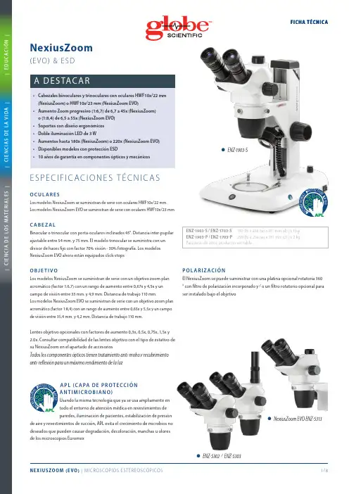
•NexiusZoom EVO ENZ-5313•ENZ-5302 / ENZ-5303paredes, iluminación de pacientes, estabilización de presiónde aire y revestimientos de succión, APL evita el crecimiento de microbios no•ENZ-1902-AP•ENZ-9505450360º| C I E N C I A D E L O S M A T E R I A L E S || C I E N C I A S D E L A V I D A || E D U C A C I ÓN |E STAT I V O S• S oportes ergonómicos con columna o piñón/cremallera con iluminación incidente y transmitida LED 3W de intensidad regulable (modelos –P y –S)• S oporte ergonómico de columna con iluminación incidente de dos brazos LED 3W y transmitida LED 3W de intensidad regulable (modelos –PG)• S oporte ergonómico de columna con iluminación incidente y transmitida con espejo orientable LED 3W de intensidad regulable (modelos –M) • S oporte universal ergonómico de un brazo o dos brazos, sin iluminación (modelos –U, -B y –BC)• S oporte articulado son base pesada o mordaza mesa, sin soporte de cabezal, sin iluminación (modelos –A y –AP)Todos los soportes de columna o piñón/cremallera se suministran con dos pinzas sujeta muestras. Fabricados en metal y con recubrimiento de pintura de alta resistenciaP L AT I N A O P C I O N A LPlatina móvil X-Y opcional de 180 x 155 mm . con desplazamiento de 76 x 55mm. y base transparente compatible con todos los modelos de NexiusZoom y NexiusZoom EVO con estativo de columna o brazo fijo. Solo disponible con unidades nuevas de microscopio (requiere ser montada en fábrica). Vea imagen: ENZ-9505I L U M I N AC I ÓNLos modelos con estativo de columna (-P) o brazo fijo (-S) incluyen iluminación transmitida e incidente LED 3 W con fuente de alimentación interna 100-240 VAmbos iluminadores se pueden utilizar de manera simultánea y disponen de regulación de intensidad independiente. Los modelos con estativode columna (-M) incluyen iluminación transmitida LED 3W con espejo de desviación e incidente LED 3W con fuente de alimentación 100-240V. Los modelos con estativo de columna (-PG) incluyen iluminación transmitida LED 3W e incidente mediante dos flexos LED orientablesM Para aplicaciones de inspección y ensamblaje. La descarga electroestática (ESD) es un flujo no deseado de electricidad entre dos objetos cargados de electricidad. ESD puede causar un amplio rango de daños permanentes en componentes electrónicos de estado sólidoPor este motivo Euromex introduce en la gama NexiusZoom modelos con protección ESD. El cuerpo del microscopio estereoscópico y el soporte han sido tratados con una pintura especial que previene la descargas electroestáticas haciendo de estos modelos la mejor elección para trabajar en ambientes sensibles a la electricidad estáticaE M Incluye cable de alimentación y fusible de recambio (modelos que incorporeniluminación), funda de protección y manual de instrucciones. Caja de poliestireno™25639346339103180178220259.5310.5| C I E N C I A D E L O S M A T E R I A L E S || C I E N C I A S D E L A V I D A |FIC HA T ÉC NI C A| E D U C A C I ÓN |M O D E L O S N E X I U S Z O O M 0.67-4.5 (W F10X /22M M )M O D E L O S N E X I U S Z O O M E V O 0.65-5.5 (W F10X /23M M )M O D E L O SBinoTrinoSoporte de columna (-P)Soporte piñón/cremallera (-S)Soporte universal un brazo (-U)Soporte universal doble brazocon base(-B)Soporte universal doble brazo con mordaza mesa (-BC)Brazo articulado con mordaza mesa (-A)Brazo articulado con base pesada(-AP)Soporte con doble guía de iluminación incidente (-PG)Soporte con iluminación transmitida espejo orientable(-M)Peso (kg)ENZ-1902-P •• 5.0ENZ-1902-PG •••5.1ENZ-1902-M •••4.9ENZ-1902-S ••4.9ENZ-1902-U ••15.6ENZ-1902-B ••22.1ENZ-1902-BC ••10.5ENZ-1902-A ••8.6ENZ-1902-AP ••20.7ENZ-1903-P •• 5.2ENZ-1903-PG •••5.3ENZ-1903-M •••5.1ENZ-1903-S ••5.1ENZ-1903-U ••15.7ENZ-1903-B ••22.2ENZ-1903-BC ••10.6ENZ-1903-A ••8.7ENZ-1903-AP••20.8M O D E L O SBinoTrinoSoporte de columna (-P)Soporte piñón/cremallera(-S)Soporte universal un brazo (-U)Soporte universal doble brazo con base (-B)Soporte universal doble brazo con mordaza mesa (-BC)Brazo articulado con mordaza mesa (-A) Brazo articulado con base pesada (-AP)Soporte con doble guía de iluminación incidente (-PG)Soporte coniluminación transmitida espejo orientable(-M)Peso (kg)ENZ-1702-P •• 5.0ENZ-1702-PG •••5.1ENZ-1702-M •••4.9ENZ-1702-S ••4.9ENZ-1702-U ••15.6ENZ-1702-B ••22.1ENZ-1702-BC ••10.5ENZ-1702-A ••8.6ENZ-1702-AP ••20.7ENZ-1703-P •• 5.2ENZ-1703-PG •••5.3ENZ-1703-M •••5.1ENZ-1703-S ••5.1ENZ-1703-U ••15.7ENZ-1703-B ••22.2ENZ-1703-BC ••10.6ENZ-1703-A ••8.7ENZ-1703-AP••20.8D I ME N SI O N E SLos modelos NexiusZoom EVO ahora están equipados click-stopsENZ-8903 ENZ-8904 ENZ-8905 ENZ-8907 ENZ-8915 ENZ-8920 CO M PAT I B I L D D E L A S L E N T O B J E T I V OM O D E L O S Aumentos 0,3x Aumentos 0,4x Aumentos 0,5x Aumentos 0,75x Aumentos 1,5x Aumentos 2xENZ-9000/9005•••NexiusZoom-P, -M, -PG•••NexiusZoom-P-ESD•••NexiusZoom-S•NexiusZoom-S-ESD•••ENZ-1903-B•ENZ-1902-BC•ENZ-1903-S•ENZ-1902-M•ENZ-1902-PG•ENZ-1902-P•ENZ-1902-U• ENZ-1903-U-ESD• ENZ-1903-B-ESD• ENZ-1903-P-ESD• ENZ-1903-S-ESD•ENZ -9005•ENZ -9000•ENZ-9095sin soporte de cabezal con de iluminación (estativo -U)incidente y transmitida por (disponible para 110V y 230V)stativo de columna con iluminación LED incidente y transmitidaEl ELE-5212 en dos configuraciones diferentes EuromexMicroscopenbv•Papenkamp20•6836BDArnhem•TheNetherlands•T+31(0)263232211•****************•。

高压电子显微镜使用说明书使用说明书一、产品介绍高压电子显微镜(High Voltage Electron Microscope,简称HVEM)是一种用于观察高压环境下的微观结构和表面形貌的先进仪器。
本使用说明书将详细介绍HVEM的结构、操作方法以及注意事项。
二、产品结构HVEM由以下几个主要部分组成:1. 高压电子显微镜主机:包含高压电源、高压采集器等部件;2. 电子透镜系统:用于控制电子束的聚焦与偏转;3. 样品台:用于固定待观察样品,并提供运动控制;4. 光学系统:用于观察样品表面形貌;5. 操作控制台:提供HVEM的操作界面和参数控制等功能。
三、使用方法1. 连接电源:将HVEM主机连接到电源,并确保电源稳定;2. 打开电源:按下主机上的电源开关,待指示灯点亮后,HVEM即可启动;3. 准备样品:将待观察样品固定在样品台上,并确保样品台位置合适;4. 聚焦与偏转:通过电子透镜系统,控制电子束的聚焦与偏转,使其准确照射到样品上;5. 观察样品:通过光学系统观察并记录样品的表面形貌;6. 参数调节:根据需要,调节HVEM的参数,如电压、放大倍数等;7. 图像保存:将观察到的样品图像保存到计算机或其他存储介质上。
四、注意事项1. 安全操作:在操作HVEM时,务必佩戴适当的防护设备,如护目镜、手套等;2. 清洁维护:定期清洁HVEM的各个部件,确保其正常运行;3. 参数选取:根据样品的特性和需要,选择合适的HVEM参数;4. 避免碰撞:在移动样品或调整HVEM配置时,需避免碰撞或撞击;5. 定期维修:按照产品说明书的要求,定期对HVEM进行维修和保养。
五、故障排除若在使用HVEM过程中遇到以下问题,请参考以下解决方案:1. 电源故障:检查电源连接是否松脱,确保电源稳定;2. 图像模糊:调整电子透镜系统,确保电子束聚焦准确;3. 无图像显示:检查光学系统连接是否正常,确保信号传输顺畅;4. 功能失效:检查HVEM参数设置是否正确,遵循正确的操作流程。

电子显微镜使用方法说明书一、简介电子显微镜(Electron Microscope,简称EM)是一种利用电子束来观察样品细微结构的强大工具。
相比传统光学显微镜,电子显微镜具有更高的放大倍数和更好的分辨率。
本说明书旨在介绍电子显微镜的使用方法,包括仪器的操作流程、样品的制备及观察技巧等。
二、仪器操作步骤1. 准备工作在使用电子显微镜之前,确保仪器已经接通电源并处于稳定的工作状态。
检查真空系统是否正常运行,以确保样品在低压环境中观察。
2. 打开电子显微镜软件将电子显微镜软件(如FEI Amira)打开,并通过USB或网络连接与显微镜主机进行链接。
3. 加载样品将待观察的样品放置在样品台上,并固定好。
根据样品的特性以及观察目的,可进行一些必要的预处理,如切片、腐蚀、染色等。
4. 调整参数根据样品的特性及所需观察的细节,适当调整电子束的加速电压、束流强度以及焦点等参数。
通过直接调整软件界面上的相应滑块或输入框来实现。
5. 对焦和定位利用显微镜软件中的对焦功能,通过调节样品台的高度和微调焦距来使样品清晰可见。
此外,通过在显微镜软件中的光学影像观察界面,可对样品在显微镜视野中的位置进行微调。
6. 观察和记录在样品清晰可见且位于所需位置后,可以开始观察并获取所需图像。
可以通过调整对比度、亮度、缩放等参数来优化图像质量。
同时,可以通过显微镜软件进行图像的实时保存和记录。
三、样品制备技巧1. 样品选择根据所需观察的目的,选择与其性质和尺寸相适应的样品。
常见的样品包括金属、细菌、细胞、纤维等。
2. 样品固定根据样品的特性,采用合适的固定方法,例如冰冻法、固定液固定法等。
确保样品在固定过程中不会失去结构和形态。
3. 制备薄切片对于较大的样品,需要进行薄切片制备。
使用合适的切片工具,如超薄切片机,将样品切割成足够薄的切片,以便电子束穿透。
4. 表面处理对于某些样品,如纤维或材料表面,可能需要进行特殊的处理。
例如,可以采用金属镀膜技术来提高样品的导电性。

多功能电子显微镜使用方法说明书使用方法说明书序言多功能电子显微镜是一种高科技仪器,它可以帮助我们观察微小物体并获得清晰的图像。
本说明书将详细介绍多功能电子显微镜的使用方法,以便用户能够正确操作并获得最佳的观察效果。
一、仪器介绍1. 多功能电子显微镜的外观和主要组成部分:外观:多功能电子显微镜包含显微镜主体、支架、控制面板等部分。
主要组成部分:多功能电子显微镜主要由光学镜头、电子显微镜头、图像处理芯片等组成。
二、准备工作1. 放置将多功能电子显微镜放在平坦稳固的桌面上,并确保四周环境明亮,避免阴影对观察造成干扰。
2. 连接电源和电源线将电源线插入多功能电子显微镜的电源接口,并将另一端插入电源插座,确保电源供应正常。
3. 开机通过控制面板上的开关按钮,启动多功能电子显微镜。
等待片刻,直到仪器完全启动并处于工作状态。
三、观察操作1. 调节焦距通过旋转光学镜头的对焦环,可以调节焦距。
根据被观察物体的大小和需求,适时调整焦距,以确保图像清晰可见。
2. 切换观察模式多功能电子显微镜有光学模式和电子模式两种观察模式。
在不同的观察需求下,通过控制面板上的模式切换按钮,可以方便地切换观察模式。
3. 调整亮度根据观察需求,通过控制面板上的亮度调节按钮,可以调整观察图像的亮度。
适当的亮度调节可以帮助我们更清楚地观察被观察物体的细节。
4. 拍摄图像多功能电子显微镜还具备拍摄功能,可以帮助用户记录观察到的图像。
在观察到感兴趣的目标时,只需按下控制面板上的拍照按钮即可。
拍摄的图像将自动保存在多功能电子显微镜的存储设备中。
5. 调整放大倍数多功能电子显微镜具备不同的放大倍数可供选择。
通过控制面板上的放大调节按钮,可以根据观察需求调整放大倍数,获得更详细的图像。
四、注意事项1. 操作正确在使用多功能电子显微镜前,请仔细阅读本说明书,并按照说明书的步骤正确操作。
不正确的操作可能导致观察结果不准确或损坏仪器。
2. 长时间使用多功能电子显微镜在长时间使用后可能会发热,请在使用过程中注意仪器的散热情况,避免过热带来的损害。
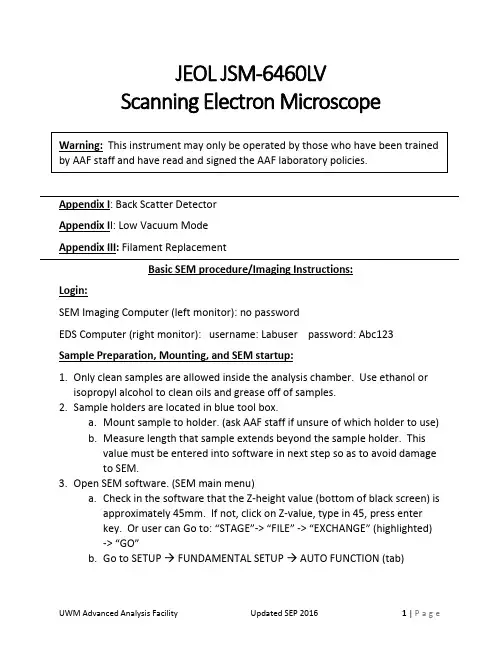
JEOL JSM-6460LVScanning Electron MicroscopeAppendix I: Back Scatter DetectorAppendix I I: Low Vacuum ModeAppendix III: Filament ReplacementBasic SEM procedure/Imaging Instructions:Login:SEM Imaging Computer (left monitor): no passwordEDS Computer (right monitor): username: Labuser password: Abc123 Sample Preparation, Mounting, and SEM startup:1.Only clean samples are allowed inside the analysis chamber. Use ethanol or isopropyl alcohol to clean oils and grease off of samples.2.Sample holders are located in blue tool box.a.Mount sample to holder. (ask AAF staff if unsure of which holder to use)b.Measure length that sample extends beyond the sample holder. Thisvalue must be entered into software in next step so as to avoid damageto SEM.3.Open SEM software. (SEM main menu)a.Check in the software that the Z-height value (bottom of black screen) isapproximately 45mm. If not, click on Z-value, type in 45, press enterkey. Or user can Go to: “STAGE”-> “FILE” -> “EXCHANGE” (highlighted)-> “GO”b.Go to SETUP → FUNDAMENTAL SETUP → AUTO FUNCTION (tab)•Input z-height value of your sample above the sample holder(specimen height).•Click okay and close the stage control window.c.On the main software window click the STAGE icon HOLDER• Choose the type of holder you are using.•In stage centered window blue line is sample height position,green line is sample holder position (blue line should be abovegreen line).•Close window.d.Go to desktop and open “IRCamera” software. Double click.4.Press VENT CHAMBER button on front of SEM (remove sample door clamp before).5.After VENT CHAMBER light stops blinking, open the chamber door.•Do you need to use the Backscatter Detector (BSE)?o If yes, see that the backscatter detector is properly positioned belowthe pole piece (if unsure, see Appendix II and AAF staff).o If no, see that the backscatter detector is lifted away from the polepiece (if unsure, see AAF staff).6.Insert sample with the special black handle tongs or carefully by hand. NOTE: the sample holder can only be inserted one way (make sure sample is fully inserted). If it doesn’t seem to fit, do not force it!7.Close the chamber door and clamp down.8.Press EVAC button on front of SEM and allow to pump down for7 minutes.9.After 7 minutes, the high voltage “HT” icon at the top left of the JEOL SEM software should say “ready”.a.If it does, click the icon.SEM Imaging and Saving Image Files:10.Move sample to location under electron beam. Check sample (xy) position via stage icon (move Z to ~25mm or sample to at least 15mm below pole piece—see IR image).11.Focus on sample at about 50X (coarse focus, then fine focus) and click “ABC” (Auto Brightness & Contrast)12.Check working distance of focused sample.13.Choose an accelerating voltage. To adjust, click on the “acc. volt” value near bottom of the screen and double click on the value you desire, 15kV normal (Higher kV sharpens image, but possible damage to sample. Lower kV more surface detail).14. Choose a spot size (generally 35). To adjust, click on the spot size value and adjust the slider bar.15. Now that the sample is focused, working distance (WD) can be adjusted.***Make sure the WD (when focused on highest point on sample) is NEVER below 10mm. If it is, catastrophic damage to backscatter detector can occur** •Based on the current WD value, adjust the Z-value so that WD will be13mm after refocusing.•Emergency stop for stage movement is to push down on black joystick.•For example:If currently Z-value = 45mm, WD = 22mmAdjust Z-value to 36mm, refocus and check that WD now = 13mm16. Sample should now be in focus and WD= 13mm.a.Magnification can be adjusted as desiredb.Fine focus with knobs on control board.c.Adjust X & Y stigmators with knobs on control board.17. At top of screen there are four options for image scan rate (scan 1, 2, 3, 4)a.Scan rate 2 is generally chosen for focusing on sample.b.Scan rate 3 or 4 (slower) are chosen for image capture.18. To capture an image, click the “Freeze” button. Then, save the image to your folder.19. If image moves (up/down or left/right) while focusing, adjust wobble.20. Should be able to get ≥20,000x magnification image s.SEM Procedures After Imaging is Complete:21. Return sample WD to 45mm.22.R eturn sample to exchange position “Stage”->”File”->”Exchange” (highlighted) -> “GO”23. Adjust magnification to 50,000X24. Turn off electron beam by clicking “HT” button at top left of screen.25. Press “VENT” on front of instrument. Wait until “VENT” button stops blinking and then can open chamber door.26. Remove sample using special black handle tongs or carefully by hand.27. Close chamber door and press “EVAC” again. (Chamber must always be under vacuum except when installing or removing sample.)28. Fill out JEOL SEM Logbook with user’s name, PI’s name, sample type,time/date.Promptly report any issues to AAF StaffAppendix I: Back Scatter Detector (BEIW)Under typical SEM imaging, a secondary electron detector is used. Secondary electron detectors require high vacuum and provide surface topography contrast for imaging. Image formation is due to inelastic collision of high energy electrons which impact the sample surface (data from top 5-50nm). Other high energy electrons from the electron beam do not interact with the sample surface. These elastically scattered electrons (data from top 50-300nm) are scattered at large angles to the sample surface and are useful for elemental contrast (z-contrast). BSE detectors do not require high vacuum and therefore in additional to providing z-contrast, are used for imaging under low-vacuum mode (appendix II).3-segment detector (segments A,B, and C)Topo = surface topography (A-B)Compo = Z contrast (A+B)Shadow = Enhances Topo mode1.Only one detector can be used simultaneously, either secondary electrondetector (SEI), or backscatter electron detector (BEIW).2.To use the BEIW, make sure that the detector is properly positionedunderneath the pole piece.3.Follow same steps outlined in main procedure through step #8.4.Then, click on “Signal” at the bottom of the JEOL SEM software window.5.Select BEIW and double click.6.When finished, set the detector type back to SEI and follow same steps asoutlined in main procedure to turn off beam, remove sample, etc.Appendix II: Low Vacuum ModeLow vacuum mode allows for imaging of non-conductive samples without the need for sputter coating. Low vacuum mode can also be used for samples with moderate vapor pressure (see AAF staff for more information). Only the back scatter electron detector (BEIW) can be used when in low vacuum mode.1.Follow steps outline in main procedure through step 7 EXCEPT thatelectrical isolation sample holder must be used.**Do not press EVAC until low vacuum mode AND BEIW is set up!**2.On JEOL SEM software click “Signal” and change to BEIW.3.On JEOL SEM software click “Vac. Mode” at bottom of screen.4.Will be prompted: “Are you sure you want to change to Low Vacuummode?”•Click Yes.5.Start low vacuum mode at about 30-40Pa. (conversion: 1Pa = 7.5mTorr)6.Now, press “Evac” button on front of instrument.7.Once Evac button stops blinking, the high voltage “HT” icon at the topleft of the JEOL SEM software should say “ready”.If it does, click the icon.8.Now, main procedure guidelines for imaging and SEM shutdown can befollowed.9.As a final step, once you are done and sample is removed from chamberadjust the “Signal” back to SEI and “Vac. Mode” back to High Vacuum.Appendix III:JEOL JSM-6460LV Filament Replacement:Filament replacement is necessary every few months of regular use or when system vacuum is poor. JEOL SEM software will indicate filament burnt out with an error message. Additionally, “LC current” (load current) display value will be low or near zero mA. Load current (mA) during regular use will be about five times the accelerating voltage (kV) value being used.1.If microscope was being used for imaging for any length of time before burn-out theelectron gun (filament and Wehnelt cap) will be very hot.•Allow the electron gun to cool for several minutes under vented conditions before attempting to replace the filament.ing nitrile inspection gloves, open the electron gun on top of the column and removethe Wehnelt by pulling it straight out.3.Disassemble the Wehnelt by loosening the external set screws that hold the ceramicbase of the filament in place and pull the filament out by the electrode prongs.4.Visually inspect the filament using a stereo microscope to verify the mode of failure (SeeJEOL manual page 5-7 for more information).5.Clean the Wehnelt cap with metal polish followed by isopropyl alcohol rinse.6.Install a new filament in the reverse procedure:a.Important: Make certain that the spacer is seated all the way down in theWehnelt cap and that scribe mark is facing the correct direction.b.Insert the new filament with the guide groove facing the correct direction.c.Visually check the filament position using a stereo microscope. The Filament tipshould automatically be centered and positioned slightly below the cone tip holein the Wehnelt cap.7.Open the electron gun on the top of the column.8.Align the guide groove on the Wehnelt with the guide pin on the electron gun and thenpush in the Wehnelt until it clicks into position.9.Close the electron gun cap making sure that the o-ring is seated properly.10.Press EVAC on the front of the system.11.Once the EVAC button stops flashing and the “HT ready” icon appears on the mainsoftware window, click the icon to turn HT on (accelerating voltage).12.Perform gun alignment (use semi-auto gun align, NOT auto).a.Manually move scroll bars to fine tune the gun alignment.。
Micro CaptureUser Manual(中文)首先非常感谢您购买了本公司数码显微镜。
这是本产品的基本功能示意图描述:数码显微镜使用简单,只需要同电脑USB连接就可以使用,本产品还配备测量软件,可做简单的测量,使用非常方便。
为了更详细的介绍本产品,敬请耐心阅读下面的产品介绍,使用方法,注意事项。
数码显微镜应用范围非常广泛:主要使用有以下方面.1工业方面:a 、工业检视,例如电路板、精密机械等b 、印刷检视,SMT焊接检查c 、纺织检视.d、 IC表面检查2美容方面A、皮肤检视B、发根检视C、红外理疗(特定产品)3生物应用A、微生物观察。
B、动物切片观察。
C、植物病虫观察。
4其他A、扩视器,协助智障人士阅读B、宝石鉴定C、古董,字画,玉器文物等鉴定D、其他一些视频图像分析领域配件说明1. 数码显微镜主体(1台)2. 万向底座(1个)或万向升降支架(可选配)3. 光碟(驱动程序,测量软件,安装说明书)产品规格:传感器:全系列高性能美国进口感光晶片主控晶片: USB3.0超高速/USB2.0高速专用主控(视产品型号不同)放大倍率:1X ~ 1000X(具体产品型号倍率不同)拍照/录影:内置辅助光源:内置8顆SMT白光LED灯静态解析度:640x480最高达4320x3240(可按需定制)数码变焦:多段式成像距离:手动调节0~无限远影像解析度:640x480最高达4320x3240或720P/1080P(可按需定制) 固定底座:万向金属底座 (可选配用升降支架)光盘:內含驱动,测量软件,说明书支持系統:WIN XP/VISTA;WIN 7 WIN 8 32位和64位电源: USB(5V DC)电脑介面:USB 3.0&USB 2.0 相容动态帧数 : 30f/s Under 600 LUX Brightness亮度范围: 0 ~ 30000LUX线控可调硬件需求:主頻700M Hz或以上;1G硬盘 CD ROM光碟机;64MB记忆件支持语言:中文(简)中文(繁体)英(其他語言需要定制)产品颜色:磨砂黑色,其他颜色可定制主体尺寸112 mm(长 ) 33 mm ( 外径)单机包裝重量380g安全警告及注意事项:1. 勿自行拆解本产品,以避免静电击穿精密芯片。
Instructions f or o perating J EOL J SM-‐7500FA a nalytical field e mission s canning e lectron m icroscope a t Nanomicroscopy C enterVersion 2.1 (April 2011)Juuso K orhonen (***********************)Latest v ersion o f t his d ocument c an a lways b e d ownloaded f rom:k.fi/en/instruments/sem/jsm-‐7500fa/SEM-‐instructions.pdfOfficial i nformationNew u ser t rainingInexperienced u sers h ave a c ouple o f o ptions, l isted b elow i n t he o rder o f preference.1.Ask f or t raining f rom t he m ost e xperienced S EM u ser o f y ourresearch g roup.2.Attend t o t he c ourses T fy-‐125.4313 a nd T fy-‐125.4314 M icroscopyof n anomaterials (5+5 c r). T hey a re l ectured e ach s pring b y P rof.Janne R uokolainen.3.Ask o ne o f t he a dministrators t o a rrange a t raining s ession.a.Small g roups o f 2-‐3 p eople a re p referred f or t he t rainings.Allow s ome t ime t o g ather e nough p eople f or t he g roup.b.Training i s d one u sing a p ractice s ample a nd p ersonalsamples a re u sually n ot i maged.Experienced u sers c an c ontact o ne o f t he a dministrators f or a s hort introduction t o t he e quipment.Every n ew u ser h as t o b e a pproved b y o ne o f t he a dministrators b efore t hey are a llowed t o u se t he S EM o n t heir o wn. T he a dministrator k eeps a s hort (15-‐30 m in) s ession w here t he e ssential s kills o f t he u ser a re c hecked. User a pplicationUser a pplication h as t o b e f illed i n o rder t o g ain r eservation a ccess t o a ny o f the N MC e quipment. T he f orm c an b e f ound f romk.fi/en/documents/nmc_user_application_form.pdf a nd i t i s returned t o o ne o f t he a dministrators f or a pproval.PricingBilling i s d one u sing t he c urrent N MC p rice l ist. C ontact P rof. J anne Ruokolainen f or t he m ost c urrent l ist. P lease n ote t hat i ndividual t raining given b y t he a dministrators w ill a lso b e c harged.Precautions – r ead c arefully•Always c heck t he l iquid n itrogen l evel a nd f ill i f n ecessary.o First u ser o f t he d ay a lways f ills t he t ank.•Keep a ll p arts c lean a nd c lean t hem i f n ecessary w ith e thanol.o Wear g loves w hen h andling h olders.•Fill t he l og b ook o n t he c omputer.o Mark a ny s trange b ehavior o r p roblems t o t he l og b ook.•If s omething i s m issing f rom t he S EM o r f rom t he s ample p reparation room (e.g. g loves, e thanol, h olders, c arbon t ape), p lease i nform o ne o fthe a dministrators (send e mail o r c all).•Use o nly f eatures y ou a re t rained t o u se. F or e xample, d o n ot u se EDS o r R BEI i f y ou d on’t k now h ow t o o perate t hem s afely.•Use o f U SB s ticks i s s trictly p rohibited d ue t o s ecurity i ssues a nd hardware i ncompatibility.•Stay c alm a nd u se y our c ommon s ense.•Contact a dministrators i f y ou a re i n d oubt. C ontact i nformation i s found o n t he l ast p age o f t hese i nstructions.Quick s tartup p rocedure1.Turn o n b oth m onitors a nd c heck t hat S EM s oftware a nd u sage l og(Excel) a re r unning. S tart t hem i f n ecessary. L og i n a s G uest (nopassword).2.Check t he l iquid n itrogen l evel a nd f ill i f n ecessary. T he f irst u serof t he d ay a lways f ills t he t ank.3.Fill t he u sage l og:a.Date, s tart t ime (and e nd t ime).b.Your n ame (and t he n ame o f y our h ost i f y ou d o n ot h avereservation p ermissions).c.Vacuum l evels b efore s tarting.d.Amount o f f illed l iquid n itrogen (write “0” i f y ou o nlychecked t he l evel).e.Write n otes a nd c omments t o t he l ast f ield i s n ecessary.f.Save t he f ile (Ctrl-‐S).4.Prepare y our s ample.5.Insert s ample i nto m icroscope:a.Press E xchange p osition.b.Press a nd h old V ENT f or c a. 1 s ec. O pen s ecuring l atch. W ait.c.Open c hamber a nd i nsert h older a long t he d irection o f t hearrows.d.Close c hamber.e.Press a nd h old E VAC f or c a. 1 s ec. W ait u ntil b linking s tops.f.Operate t he r od t o m ove t he s ample t o t he s tage. I f y ou’re n otabsolutely c ertain h ow t o d o t his, r ead t he d etailedinstructions!g.Take o ut t he r od.6.Wait u ntil v acuum l evel r eaches l ess t han 5⋅10-‐4 P a.7.Set E mission c urrent t o 10 μA.8.Select A cceleration v oltage.9.Press O bservation O N.Shutdown p rocedure1.Press O bservation O FF t o t urn o ff a cceleration v oltage.2.Press E xchange p osition.3.Take o ut h older u sing t he r od.4.Press a nd h old V ENT f or c a. 1 s ec. O pen s ecuring l atch. W ait.5.Open c hamber a nd t ake o ut t he h older.6.Close c hamber.7.Press a nd h old E VAC f or c a. 1 s ec.8.Mark e nding t ime a nd o bservations t o U sage l og a nd s ave f ile (Ctrl-‐S).9.Set S EM M onitor s oftware t o n ormal s ettings:a.Exchange p osition p ressed (green).b.Mode: S EMc.Magnification: m inimum f or b oth S EM a nd L Md.Probe c urrent: 810.Turn o ff s pecial f eatures y ou h ave u sed: I mage r otation, d ynamicfocus, e tc.11.If y ou m ade a ny c hanges i n t he O peration S ettings m enu, c hangethem t o n ormal v alues (scan s peeds, i mage f unction, e tc.).12.Clean t he h olders w ith e thanol i f n ecessary.13.Clean t ables. I f y ou w ant t o s tore y our s amples, m ark t hem w ith y ourname a nd p ut t hem o nto a s helf. T hings l eft o n t he t able a re t hrowninto t he t rash.14.Transfer y our i mages f rom t he s mall c omputer o n t he b ack t able.You c an f ind y our f iles a t t he n etwork d rive c alled H arley.e U SB s tick, S SH, e mail, o r b urn a C D.b.The f iles c annot b e t ransferred d irectly f rom t he S EMcomputer d ue t o s ecurity r easons.15.Turn o ff m onitors. D o n ot l og o ut f rom t he s oftware o r c lose t heExcel l og b ook.Changing s ample1.Press O bservation O FF t o t urn o ff a cceleration v oltage.2.Press E xchange P osition t o m ove t he s tage t o c orrect p osition.3.Take s ample o ut b y o perating t he r od.4.Press a nd h old V ENT f or c a. 1 s ec. t o f lush c hamber a nd o pen l atch.Wait.5.Open c hamber a nd t ake o ut s ample (pull a long t he a rrows, n ot u p).6.Change s ample a nd i nsert h older a long t he a rrows.7.Close c hamber a nd s ecure w ith l atch.8.Press a nd h old E VAC f or c a. 1 s ec. W ait u ntil b linking s tops.9.Insert s ample b y o perating t he r od. T ake o ut r od.10.Wait u ntil c hamber v acuum r eaches 5⋅10-‐4 P a b efore t urning o nacceleration v oltage.Special f eaturesThis i s o nly a q uick r eference. S pecial t raining i s r equired t o u se R BEI o r E DS, because o f s afety i ssues.Infrared c ameraYou c an s ee i nside t he c hamber u sing t he i nfrared c amera.1.Switch c amera o n f rom t he b utton o n t he t able.2.From S EM s oftware s elect N avigator -‐> I nfrared c amera3.Turn c amera o ff w hen u sing R BEI o r E DS.Probe c urrent m eterProbe c urrent m eter c an b e u sed t o c heck t he c urrent g oing t o t he s ample. I t is m ost i mportant i n E DS a nalysis.1.Insert t he d etector b y c hecking P CD f rom t he b ottom r ight c orner o fSEM s oftware.2.Take o ut d etector a fter y ou h ave r ead t he c urrent f rom t he S EMsoftware.Retractable b ackscattering d etector (RBEI)Backscattering d etector i s u sed t o d istinguish b etween e lements o n t he sample.1.Set w orking d istance t o 8 m m o r m ore.a.Inserting R BEI w ith l ess t han 8 m m b etween t he s ample a ndthe o bjective l ens w ill r esult i n s erious d amage.2.Turn o ff i nfrared c amera.3.Insert d etector b y c hecking R BEI f rom t he b ottom r ight c orner o f t heSEM s oftware.4.Select C OMPO o r T OPO f or i mage m ode (same m enu a s S EM a nd L M)and u ser a s low s canning s peed f or o bservation.X-‐ray a nalysis (EDS)This g uide i s n ot a dequate f or p roper o peration o f E DS, b ut i s o nly a q uick reference f or t rained u sers.1.Set w orking d istance t o e xactly 8 m m.a.Focus w ith Z h eight u sing t he r ing o f t he s croll w heel i nsteadof F OCUS.2.Insert R BEI.3.Turn o n b ias v oltage b y c licking t he l ightning i ndicator.a.Wait u ntil c ount r ate s tabilizes.4.Select A nalysis f rom t he r ight s ide o f S EM s oftware.5.Click D T (dead t ime) a nd s elect T4 f rom t he l ist.6.Adjust p robe c urrent s o D T b ecomes g reen (around 20-‐30 %) a ndcount r ate i s c a. 2000-‐3000 c ps.7.Take s pectra, l ine s can, o r m apping u sing t he a ppropriate b uttons.8.When a sked a bout s aving t o a n etwork d rive, s elect O K.9.Save t he a nalysis b efore e xiting a nalysis m ode i n o rder t o b e a ble t oreturn t o t he a nalysis l ater.a.Exporting o nly s aves t he i mage a nd y ou c annot r eturn t omake m ore a nalysis o n t he d ata.10.When y ou a re f inished w ith a nalysis, t urn o ff t he b ias v oltage a ndtake o ut R BEI.Saving E DS s pectraIf y ou w ant t o b e a ble t o p lot y our E DS s pectrum, s elect E xport a nd t hen select M SA f ile. I t w ill s ave t he s pectrum i n a c ompatible f ile f or u se i n O rigin, Excel, o r s ome o ther p lotting p rogram.Detailed i nstructionsOperating t he r od (sample e xchange m echanism)This p rocedure d escribes h ow t o u se t he s ample e xchange m echanism i norder t o e ither r emove o r i nsert a s ample h older i nto/from t he m icroscope.Read t his s ection c ompletely t hrough b efore p roceeding a nd m ake s ure t hatyou u nderstand e very s tep.Precondition: T he e xchange c hamber i s i n v acuum a nd t he d oor s eparatingit f rom t he m icroscope i s o pen. C onfirm t hat E VAC l ight i s l it a nd n otblinking. D epending o n w hether y ou a re i nserting o r t aking o ut a s ample, t heholder m ight b e i n t he e xchange c ompartment (HLDR l ight i s o ff) o r i nsidethe m icroscope (HLDR l ight i s o n).See t he v ideo o n t he c omputer d esktop f or a d emonstration. U PDATE: T hefigures a re f rom a n o ld v ersion o f r od.1.Push t he b ar i nside t he m icroscope b y f ollowing t he p rocedure:a.Lower t he r od t o h orizontal l evel, w hile l ightly h olding i tback.b.Let t he r od b e p ulled i n s lowly.c.Push t he b ar g ently a ll t he w ay i nside u ntil i t s tops (d).•There i s a l ittle r esistance a t t he f inal c ouple o fcentimeters.•The s ample s hould b e n ow e ither r eleased f romthe b ar o r a ttached t o i t (depending o n w hetheryou a re i nserting o r r emoving t he h older).•If y ou h ave n ot p ushed t he s ample a ll t he w ayinside a nd s tart t o p ull b ackwards t here i s adanger t hat t he s ample h older w ill f all t o t hebottom t he s ample c ompartment. I f t his h appens,the w hole s ample c ompartment h as t o b e o pened.Contact S EM a dministrators i n t his c ase.2.Pull t he b ar o ut f rom t he m icroscope u sing t he f ollowingprocedure:a.Pull t he b ar o ut a s f ar a s i t c omes (e).•The t wo a rrows o n t he h older s hould a lign w iththe p ipe e nd.•If y ou h ave n ot p ulled f ar e nough, t he r od m ightbe d amaged d uring t he l ift.b.Lift t he r od u pwards t o v ertical.•Now y ou s hould e ither h ave t he s ample i nside t hemicroscope o r i n t he e xchange c ompartment a ndthe e xchange c ompartment i s i n v acuum.Opening t he s ample e xchange c ompartmentThe f ollowing p rocedure d escribes h ow t o b ring t he e xchangecompartment t o a tmospheric p ressure.Precondition: T here i s n o s ample i nside t he m icroscope o r i t h as b eenbrought t o t he e xchange c ompartment, a nd t he e xchange c ompartment i sin v acuum. F irst c heck t hat H LDR l ight i s o ff o n t he s ample e xchangecompartment (i.e. t here i s n o s ample i nside t he s ample c ompartment).Figure. S ample e xchange r od1.Pressurize t he e xchange c ompartment:a.Press a nd h old (for a bout 1 s econd) t he V ENT b utton o n t heexchange c ompartment.i.The b utton s tarts t o b link a nd y ou h ear s ome s ounds.ii.In a f ew s econds, t he d oor b etween t he e xchangecompartment a nd t he s ample c ompartment c loses.You c an o bserve t his b y e ar a nd b y l ooking a t t hebottom r ight c orner o f t he S EM M onitor.2.Open t he l atch a s s oon a s y ou h ear t he c lick.3.Open t he e xchange c ompartment d oor (it s hould o pen a lmost b yitself).a.You d o n ot n eed t o w ait u ntil t he p umping h as s topped.b.The c ompartment w ill c ontinue p urging f or a f ixed a mount o ftime. Y ou d o n ot h ave t o w ait u ntil i t s tops a nd y ou c anevacuate i t a s s oon a s y ou l ike.4.Now y ou h ave t he s ample c ompartment o pen a nd r eady f orloading/unloading t he s ample h older.Inserting a s amplePrecondition: T here i s n o s ample i nside t he s pecimen c hamber a nd exchange c ompartment i s i n v acuum. F irst c heck t hat H LDR l ight i s o ff o n the e xchange c ompartment (i.e. t here i s n o s ample i nside).1.Move t he s tage t o e xchange p osition:a.Click E xchange P osition o n t he S EM M onitor.i.If b utton i s n ot v isible, c lick "Specimen" f rom t herightmost e dge o f S EM M onitor.ii.Make s ure t hat E XCH P OSN i s l it o n t he e xchangecompartment, b efore p roceeding.2.Bring t he e xchange c ompartment t o a tmospheric p ressure b yfollowing p rocedure i n s ection “Opening t he s ample e xchangecompartment”. Q uick n otes:a.Press a nd h old V ENT f or c a. 1 s ec.b.Open l atch. W ait.c.Open c hamber d oor.3.Put o n g loves i f y ou d o n ot h ave t hem a lready o n.a.Parts t hat a re i n c ontact w ith t he v acuum s hould b e k eptabsolutely c lean. I f y ou h ave t ouched s ome p art, c lean t he p artwith e thanol (not a cetone).4.Insert h older t o t he s pecimen c huck:a.Slide t he s pecimen h older i nto t he s pecimen c huck a long t hearrow d irection o n t he s pecimen h older.5.Check t hat t he O-‐ring s eal o n t he d oor i s O K a nd w ipe i t w ith a c leanglove i f n eeded t o g et r id o f a ny d ust.a.If t he r ing i s r eally d irty, w ipe i t w ith e thanol o r i sopropanol(do n ot u se a cetone o r m ethanol).6.Close t he c hamber d oor a nd s ecure i t w ith t he l atch.7.Evacuate t he c ompartment b y p ressing a nd h olding E VAC (forabout 1 s econd). T he l ight w ill s tart b linking.a.Wait u ntil t he l ight s tops b linking a nd t he d oor s eparatingthe e xchange c ompartment i s c losed. Y ou c an o bserve t hisfrom t he b ottom r ight p art o f t he S EM M onitor.8.Insert t he s ample h older i nside t he m icroscopea.Refer t o s ection “Operating t he r od” i f i n d oubt.9.A p opup w indow s hould a ppear o n t he S EM M onitor. N ow s elect t heappropriate h older a nd s et t he o ffset v alue.a.If p opup d oes n ot a ppear, t ake o ut t he h older a nd i nsert i tagain.10.Wait u ntil t he v acuum l evel r eaches 9.6·10-‐5 P a (if t hat i s n otpossible, w ait a t l east u ntil 5·10-‐4 P a).Taking o ut s amplePrecondition: T here i s a s ample i nside t he m icroscope a nd e xchange compartment i s i n v acuum. F irst c heck t hat H LDR l ight i s o n o n t he s ample exchange c ompartment (i.e. t here i s a s ample i nside) a nd E VAC l ight i s o n and n ot b linking.1.Click O bservation O FF t o t urn o ff a cceleration v oltage.2.Click E xchange P osition t o m ove t he s ample h older t o t he e xchangeposition.a.Make s ure t hat E XCH P OSN i s l it o n t he e xchangecompartment b efore p roceeding.3.Bring t he s ample t o t he e xchange c ompartment b y o perating t herod.a.Refer t o s ection “Operating t he r od” i f y ou a re n ot a bsolutelycertain h ow t o d o t his.4.Pressurize t he e xchange c ompartment:a.Press a nd h old V ENT f or c a. 1 s ec u ntil i t s tarts t o b link.b.Open s ecuring l atch. W ait.c.Open c hamber d oor.5.Now y ou h ave t he s ample c ompartment o pen a nd y ou a re r eady t akeout y our s ample. I f y ou a re d one w ith t he i maging, j ust c lose t heexchange c hamber a nd e vacuate i t o therwise c ontinue w ith i nsertinga n ew s ample. D o n ot l eave t he c hamber o pen f or a l ong p eriod o ftime, b ut e vacuate i t i f n eeded.Sample h oldersSample h olders c onsist o f a b ase p art a nd a n a dapter p art (show o n t he f igure right). T here a re t hree d ifferent a dapters f or d ifferent s pecimen s tubs s hown in t he f igure b elow (a, b , c , d ).The m ost b asic h olders a re t he 12.5 m m (b-‐1) a nd 25 m m (c-‐1) a luminum “JEOL” s tubs . T hey s hould b e u sed w henever p ossible. S tubs s hould a lways b e available a t t he s ample p reparation r oom, b ut y ou c an a lso o rder y our o wn ones e .g. f rom E MS (order n umbers 75730, a nd 75700). T he u se o f r egular holders i s i ncluded i n t he o peration p rice o f t he m icroscope.Also “mini-‐stubs” a re a vailable f or u se w ith a p rovided a dapter. T hey a re preferred f or s mall s amples. T hey c an b e o rdered f rom T ed P ella (order numbers 16180, a nd 16181).For s pecial o ccasions, a H itachi a dapter (a) c an b e u sed. S pecial c are m ust b e taken w hen u sing t hese h olders, b ecause t hey l ack s ome s afety f eatures. Ask a dministrators, i f y ou h ave s pecial r equests f or h olders. T here a re a lso different k inds o f c ross-‐section h olders a vailable. A sk t he a dministrators f or more i nformation.Attaching a dapter t o b ase p arta) Make s ure t hat p arts a re n ot d irty, c lean i f n ecessary. b) Place a dapter o n t he b ase p art.c) Tighten s crew o n t he b ase p art l ightly.Figure. A ttaching a dapter t o base p art.Figure. 12.5 m m a nd 25 m m "JEOL" stubs.Figure. "Mini-‐stubs" a nd 12.5 m m a dapter.Figure. C ross-‐section holders.Sample h eightAlign t he t op o f t he s ample w ith t he g roove i nside t he J EOL a dapter p art. U se the s crew o n b ottom t o r aise o f l ower t he s ample. W hen u sing a nother holder, m ake s ure t hat h eight f rom t able t op l evel i s e xactly 25 m m.CoatingFor n on-‐conductive s amples a c oating i s u sually n eeded f or o bservation i n SEM. T his c an b e e asily p erformed b y u sing s putter c oating o f g old, p latinum, or g old-‐palladium. T here i s a s putter c oater a t N MC, w hich c an b e u sed f or this p urpose. R esolution l imiting f actor i s t he g rain s ize, w hich i s u sually 5-‐20 nm d epending o n t he c onditions o f s puttering.Also c arbon c oating c an b e u sed t o m ake s amples c onductive. I t i s a nappealing m ethod, w hen d oing X -‐ray a nalysis. I t c reates a v ery u niform l ayer without n oticeable grains.Figure. A lign t op o f stub w ith t he g roove on t he s ample holder.Basic m icroscope o perationBasic c onceptsWorking d istance a nd Z v alueWorking d istance (WD) v alue s ets t he e ffective f ocal l ength o f t he o bjective lens.Z h eight v alue s ets t he d istance o f t he (supposed) s urface l evel o f t he s ample from t he o bjective l ens.These t wo v alues a re e qual, w hen t op o f s ample i s a ligned w ith t he t op o f the h older (ie. 25 m m h igh f rom t able l evel, s ee f igure). W D > Z, i f y our sample i s l ower t han t he c orrect l evel a nd v ice v ersa. I f W D < Z y ou n eed t o set t he S ample O ffset v alue a ccordingly.Sample o ffsetThe h eight o f t he t op l evel o f t he s ample m easured f rom t able t op l evel should b e e xactly 25 m m. T he s ample c an b e s et a lso 0-‐4 m m h igher t han t he nominal l evel, b ut t hen t he S ample O ffset v alue h as t o b e s et a fter i nserting sample. I t i s l ocated a t t he b ottom o f t he s ample h older s elect w indow, w hich pops u p a utomatically a fter h older i nsert.Acceleration v oltage, e mission c urrent, p robe c urrent…The f irst t hing t o t hink a bout w hen s tarting i maging i s t he s election o f acceleration v oltage. T he c hoice d epends o n t he t ype o f t he s ample. S ee table b elow f or s ome e xamples.Sample Observation c ondition NotesGold p articles o n conductive s urface 5-‐30 k V, p robe c urrent a t c a. 10, working d istance 1.5-‐8 m mCoated p orous polymer 1-‐5 k V, p robe c urrent 6-‐10, w orking distance 4.5-‐8 m mUncoated p olymer 0.5-‐1 k V, p robe c urrent < 8, g entlebeam m ode, w orking d istance c a. 8mmCoated b iological sample 1-‐5 k V, p robe c urrent c a. 10, w orking distance 4.5-‐25 m m d epending o n feature s izeUncoated p aper 1-‐2 k V, g entle b eam (GB-‐L) m ode,working d istance 4.5 m m, p robecurrent 6-‐10.Coated p aper 5 k V, w orking d istance 4.5-‐25 m m,probe c urrent c a. 10X-‐ray a nalysis o f conductive s ample 15-‐30 k V, w orking d istance e xactly 8mm, h igh p robe c urrentRetractable B EIdetector i nsertedX-‐ray a nalysis o f poorly c onductive sample 5 k V, w orking d istance e xactly 8 m m,probe c urrent a s h igh a s p ossibleRetractable B EIdetector i nsertedThe e mission c urrent i s t he c urrent d rawn f rom t he e mitter. S et i t a lways t o 10 μA. Figure. S ample height s hould b e exactly 25 m m measured f rom t able top l evel.Probe c urrent i s t he c urrent d irected a t t he s ample. H igher v alues g ive better s ignal t o n oise r atio, b ut c ause m ore c harging a rtefacts i n p oorly conducting s amples. V alue o f 8-‐10 i s u sually a g ood c hoice.AligningUsually t he m icroscope i s a ligned w ell e nough f or m icrometer s cale operation. I n t his c ase, o nly f ocusing i s n ecessary. F or h igher m agnification work, t he e lectron b eam n eeds t o b e a ligned a nd a stigmatism o f t he o bjective lens h as t o b e c orrected.FocusThe f irst l evel o f a ligning i s a lways f ocusing. F ocusing i s d one u sing t he FOCUS k nob o n t he o peration c onsole. C lockwise r otation i s u nder f ocus (weaker l ens) a nd c ounterclockwise i s o ver f ocus (stronger l ens).If p ossible s elect s ome f eature, w hich y ou c an u se i n t he m agnification r ange from c a. 1000 t o 20000.Start f rom a l ow m agnification a nd w hen y ou g et g ood e nough i mage m ove on t o h igher m agnification f or f ocusing. I t t he a lignments a re r eally o ff, y ou might n ot g et a c lear i mage a t a ll.Beam a lignBeam a lign i s a lways d one a t p robe c urrent 8. S elect t he c orrect p robe current v alue f rom t he s oftware.Press A LIGN o n o peration c onsole. T he i mage s tarts t o m ove o n t he s creen. Use t he X a nd Y k nobs t o m inimize t he m ovement. P ress A LIGN O FF (STIG) button w hen i mage h as s topped. R epeat f or m agnifications u p t o c a. 20000. Focus t he i mage w henever n ecessary.Astigmatism c orrectionTo c orrect t he o bjective l ens a stigmatism p ress t he S TIG b utton o n t he operation c onsole (it i s u sually a lready s elected a t t his p oint). M ove o n t o a spherical f eature, w hich y ou a re a ble t o o bserve a t m agnification 10000 o r more.Move t he F OCUS k nob s o t hat y ou g o f rom u nderfocus t o o verfocus a nd b ack several t imes. W hen y ou h ave a stigmatism, t he i mage g ets e longated i n diagonal d irections w hen m oving a round t he f ocal p oint. S elect t he f ocal point w here n o e longation o ccurs.Adjust t he X a nd Y k nobs s o t hat y ou g et t he c learest i mage p ossible. F ocus whenever n ecessary.Other c orrectionsThere a re a lso o ther a lignments, s uch a s s ource a lign, c ondenser l ens astigmator, l ow m agnification c enter, a nd s tigmator c enter c orrections. These v alues s hould n ot u sually b e c hanged a nd t heir u se i s n ot d escribed here.Problems a nd t roubleshootingAnswers t o c ommon p roblemsI w ant t o u se U SB s tick t o t ransfer m y f iles!You c an t ransfer y our f iles t o a U SB s tick f rom t he s mall c omputer a t t he b ack wall. Y ou’ll f ind y our f iles u nder t he n etwork d rive H arley.Help! T here i s n o i mage.Follow t he c hecklist t o f ind t he c ause:1.Are y our Z a nd W D v alues t he s ame? I f n ot p ress W D t o s et c orrectdistance.2.What d etector a re y ou u sing? I f W D<8 m m y ou u sually d o n ot g etimage w ith L EI d etector; a nd i f W D>8 m m S EI g ives o nly s tatic n oise.LM m ode s hould w ork f ine i n t his c ase.3.What i s y our p robe c urrent v alue? I f i t i s l ow, t ry i ncreasing i t.4.If n one o f t he a bove i s t rue, t ry r esetting a lignment. G o t o A lignmentpanel a nd c lick R eset A ll.a.In a r eally b ad c ase t he s ource a lignment h as g one b ad.Contact a n a dministrator t o a lign i t.If t here i s n o i mage w hen s tarting o perationFirst, p ress A CB (auto c ontrast & b rightness). I f y ou e ven s ee s ome s tatic noise, y ou o nly n eed t o f ind t he c orrect f ocal p oint. S ee p revious s ection.In c ase y ou h ave c ompletely b lack s creen w hen y ou s tart i maging, f ollow t he list u ntil y ou h ave i mage.1.Restart o f S EM s oftware:a.File-‐>Exit t o g o t o l ogin s creen.b.Close l ogin s creen f rom E xit b utton.c.Wait o ne m inute.d.Start S EM_Monitor s oftware.e.Log i n a s G uest.2.Restart c omputer:a.Close S EM s oftware.b.Save E xcel l og b ook a nd e xit.c.Restart W indows.d.Start S EM s oftware a nd E xcel l og b ook.3.Restart o peration c onsole:a.Read i nstructions b elow.If v acuum b reaks d uring s ample e xchangeVacuum u sually b reaks i f t he l ever i s p ushed o r t wisted d uring t he s ample insertion. T he c omputer w ill r aise a m aintenance w indow s howing e rror messages. T he m icroscope w ill a utomatically s hut d ownsome p arts a nd t he v acuum p umps h ave t o b e r estarted. B ring t he microscope b ack t o i ts n ormal c ondition b efore p roceeding. F or e xample, lift t he r od b ack t o i ts u pright p osition.1.Locate t he t wo V AC S W b uttons b elow t he t able. T here a re a lso M AINSW b uttons, b ut d o n ot t ouch t hem.2.Shut d own v acuum p umps b y p ressing V AC O FF (0=OFF, 1=ON)button. T he p umps s hould n ow s top, i f t hey w ere n ot s hut d ownalready.3.Wait a m oment a nd r estart p umps b y p ushing V AC O N b utton.a.There i s a 20 m in t imer f or s tarting t he p umps s o y ou w illhave t o w ait a t l east 20 m inutes b efore p roceeding.4.After a ll o f t he e rror m essages h ave d isappeared f rom t he d isplay,you c an c ontinue o perating.Turning o ff c omputer1.Log o ut f rom t he S EM s oftware (File-‐>Exit).2.Save t he E xcel l og b ook (File-‐>Save o r C trl-‐S).3.Close t he E xcel l og b ook.4.Select S hutdown f rom S tart m enu.Powering o n c omputer1.Start c omputer f rom t he p ower s witch.2.Log i n a s S EMUser (password: S EMUser).3.Start E xcel l og b ook b y d ouble c licking “SEM U sage L og” o n t he r ightmonitor d esktop.4.Start S EM s oftware b y d ouble c licking S EM_Monitor.5.Log i n a s G uest.Restarting o peration c onsole1.Turn o ff c omputer.2.Press O P S W O FF f rom b elow t he t able.3.Wait c a. 10 s econds.4.Press O P S W O N.5.Turn o f c omputer.6.Wait a c ouple o f m inutes b efore s tarting S EM_Monitor s oftware.。
ex20电子显微镜使用说明书
ex20电子显微镜的低倍目镜和低倍物镜的使用(低倍镜容易找到目标):
1、准备:将显微镜取出,平放于桌面上,转动粗调焦旋钮,将镜筒略升高使物镜转换器与载物台距离拉开,以便安装物镜,按任意顺序装上三个物镜(物镜转换器有一个孔上有防尘盖,装物镜时需取下),物镜需顺着螺纹方向旋到底;取下目镜筒上的防尘盖并插上一个低倍的目镜,安装完毕将显微镜置于前方略偏左侧,必要时使镜臂倾斜以便观察。
再旋转物镜转换器,将低倍物镜对准载物台中央的通光孔(可听到“咔哒”声)。
2、对光:打开光圈,转动聚光镜使其上升(其作用是把光线集中到所要观察的标本上),双眼同时睁开,以左眼向目镜内观察,同时调节反光镜的方向,直到视野内光线明亮均匀为止。
反光镜的平面镜易把其他景物映入视野,一般用凹面镜对光,光线不足时,可使用电光源(电光源的安装见下文)。
3、放标本片:标本片朝上放到载物台上用移动尺的两个夹子夹住标本片(640倍的显微镜是用压片压住标本),调节移动尺的两个旋钮把要观察的部分移到通光孔的正中央。
4、调节焦距:从显微镜侧面注视物镜镜头,同时旋转粗调焦旋钮,使镜筒缓慢下降,大约低倍镜头与玻片间的距离约5mm时,再用左眼从目镜里观察视野,左手慢慢转动粗调焦旋钮。
Standard Operating ProcedureFEI Quanta 200 Scanning Electron Microscope This document is intended as a guide to the operation of the FEI Quanta 200ESEM by certified users. It provides details on sample loading, bringing the microscope up to operating conditions, normal operation procedures, sample removal, and returning the microscope to a powered down state. This guide is not intended for novice users.*Please fill out the log sheet before beginning using the microscope.1. Specimen Preparation and HandlingThe Quanta 200 has three operating vacuum modes to deal with different types of samples. High Vacuum (HiVac) is the conventional operating mode associated with all scanning electron microscopes. High Vacuum mode typically requires that the sample be conductive or properly mounted and coated for conduction. Coating reduces beam penetration and allows for a sharper image; however, it may mask elements of interest forX-ray analysis. The two other operating modes are Low Vacuum (LowVac) and ESEM.In these modes the column is under high vacuum and the specimen chamber is at higher pressures of 0.1 to 30 Torr. Observation of outgassing or highly charging materials can be made using one of these modes without the need to coat the sample with a conductive material. In some cases, a PLA (Pressure Limiting Aperture) cone placed on the conical objective maybe useful in LowVac mode because the gas in the chamber may cause “skirting” of the incident beam. ESEM mode is used primarily for any specimens that are considered “wet” and contain volatile components such as water or oil.The microscope is currently used in High Vacuum (HiVac) mode. If you want to use Low Vacuum please contact before Claudia Ojeda-Aristizabal or Rick Behl.Specimens should be clean, fixed, and properly mounted before loading them onto the specimen stage. The specimen must be electrically grounded to the sample holder with conductive tape or paint to minimize specimen charging.2. Computer User Interface (UI)The SEM is controlled by means of a Windows-based user interface (UI) program, calledxT Microscope Control.The primary SEM controls are accessed via the consoles on the right hand side of the screen. There are various tabs at the upper right hand side corresponding to different“pages”. The Work Page(Figure 1) contains the “Vacuum”console, the “Electron Column”console, the “Detectors”console, and the “Stage”console, with maps, coordinates, and tilt correction tabs, and finally, the “Status” console. The Options Page (Figure 2) contains the “Imaging” console. The various pages are accessed by selecting the desired tab from the top of the console.Images are displayed in the main window on the computer screen. The main windowis divided in to 4 quadrants (quads). The bottom right quadrant, quad 4, shows an infrared camera view of the inside of the SEM chamber. The upper right quadrant, quad 2, is typically used to display the secondary electron image. Quadrant 1 (upper left) may be used for the backscatter detector, and quadrant 3 (lower left) may be used to mix images from quad 1 and2.The SEM can be controlled by making selections from the Menu, clicking icons onthe Toolbar (Figure 3), or with keyboard commands (Figure 4). The mouse is also used tocontrol various functions on the SEM. The controls are discussed in detail in the following sections.Figure 1. The Work Page, located on the right side of the xT Microscope Control window.Figure 2. The Options Page, located on the right side of the xT Microscope Control window.Figure 3. The Toolbar, located on the top of the xT Microscope Control window.Figure 4. Keyboard shortcuts.3. Start up Procedure*Users must wear latex gloves when handling detectors or loading specimens.1.Fill out the Logsheet. Fill out the Date, User, Supervisor, Sample material,Acceleration Voltage, Time In, Time Out and any comments regarding the SEM (for ebeam lithography include spot sizes used and measured currents). Refer to the previous entry on the Logsheet to confirm the SEM status.2.From the xT microscope control user interface (UI), enter your Username andPassword. The general username is “supervisor”, and the password is “supervisor”.3.The column and specimen chamber are kept under vacuum when not in use to preventcontamination therefore first the system must be brought to atmospheric pressure to open the specimen chamber. First bring the stage to “Home stage” while watching the camera image, checking that the stage will not hit anything. In case of doubt, click “Stop”. Vent via the computer interface by clicking the “Vent” button on the “Vacuum” console. The program will display a prompt asking “Really vent the chamber?”. Click yes to vent the chamber.4.As the system vents, the Vacuum Status Indicator on the “Status” console willchange from green, to yellow while venting, and finally to red when vented. At this point, as you watch the camera image, open the chamber door by pulling the door carefully straight out. Check in the camera image that the stage is far from the eyepiece.5.After mounting your specimen to a specimen stub, insert the pin on the underside ofthe specimen mount into the opening in the top of the stage (see Figure 5). Use gauge to test the height of the sample before closing the door of the chamber.6.Close the chamber door as you watch the camera image and click the “Pump” buttonon the Vacuum console in the computer interface.7.Wait for 15min.During this time a green light will appear next to the vacuumpressure on the “Status” console. After 15min pumping, the accelerating voltage may be turned on by clicking on the “HV” button on the “Electron Column” console.(Even if the software allows to click “HV” before the 15min have passed, please wait.We suspect that the pressure gauge is not reading an accurate pressure in the chamber)Figure 5. Inserting the specimen stub into the stage.4. Adjusting Working Distance, Accelerating Voltage and Spot Size1.Set the highest point on the specimen to a working distance of approximately 10 mmby adjusting the z-axis on the stage. The z-axis can be changed by clicking on the camera view window or in quad 4, then clicking and holding the middle scroll button up or down over the yellow bar which will appear on the screen. It can also be changed by changing the relative coordinates in the stage menu. Approach to the 10mm mark on the screen little by little. Be prepared to stop the stage in case it gets too close to the eyepiece. Do a rough focusing on the highest point of the specimen.Once on focus, click on the icon . This couples the specimen height to the working distance.2.The accelerating voltage can be set between 0-30 kV via the “Electron column”console however, 10 kV will be adequate for most materials. For polymer and glass samples 2-6kV works well and for metals or highly conductive surfaces 30kV will provide high resolution.3.To obtain an image, click on the desired quadrant, 1, 2 or 3, and then click the rabbiticon on the toolbar for fastest render.4.Demagnify as far out as possible when setting up an image by pressing the “-“ key5.Adjust the magnification, focus, stigmator, contrast and brightness to desiredlevels as described below.6.Adjust the contrast and brightness, located on the “Detectors” console, to thedesired levels, or press F9 for the auto contrast brightness (ACB) function.7.Once the brightness and contrast have been adjusted, increase the magnificationusing the “+” key on the keyboard. Other magnification adjustments are• Higher/Lower = (+/-on num pad)• Coarse control = (Crtl key + mouse wheel up/down)• Fine control = (Shift key + mouse wheel up/down)• Round value = (*on num pad)• Select preset value from Magnification menu on the Option page8.Focus the image by holding the right mouse button and moving the mouse left orright.9.The “Spot size” on the “Electron column” console should be adjusted to improvethe image quality; however, in turn the brightness and contrast will need to be readjusted. In general, smaller spot sizes are used for high magnification/resolution while larger spot sizes are more suitable for low magnification and X-ray analysis.10.An area of interest can be moved to the center by locating the mouse pointer over itand double-clicking. To move the sample, the arrow keys, the center scroll button, the stage console, or the x, y and z knobs on the SEM chamber door can also be used.11.To optimize very high magnification imaging, the stigmator can be adjusted byholding the “Shift” key and the right mouse button simultaneously.5. Image Capture1.To capture an image, click on the desired quadrant, 1, 2 or 3.2.By clicking the “-“ button in between the “turtle” and “rabbit” buttons on the toolbarthe render speed can be decreased, thereby increasing the image quality shown on the screen and allowing for a better idea of how the final image will actually look. It is good technique to adjust the brightness and contrast a few times while switching back and forth between fast and slow raster speeds until the extremely bright regions are minimized and muddy looking regions show detailed contrast.3.To have good resolution in your saved image, the image size, located to the rightof the rabbit button, should be 1024x884. This results in an image of around 900kB.4.Now click the “camera” button on the toolbar to initiate a slow scan and capture afinal image.5.File – Save As… to save the image to the “Data” folder.All pictures should besaved under a subfolder with your Supervisor’s name.6.Transfer your images through the internet using the DELL black computer on theground (at the far left). Never insert a USB memory to the SEM computer8. Shut-down Procedure1.Reduce the magnification to its lowest value and turn off the accelerating voltage byclicking the “HV” button on the “Column” console.2.Bring the stage to home while you watch the camera image, checking that the stagewon’t hit anything inside the chamber. In cause of doubt, click “Stop”3.Once the accelerating voltage has been turned off, click the “Vent” button on the“Vacuum” console to bring the system back to ambient pressure.4.Once the system is fully vented, the “Vacuum Status” on the “Vacuum” consolewill display a red box.5.The specimen chamber can now be opened and the sample can be removed. Open thedoor carefully as you watch the camera image to check that the stage won’t hit anything, in particular the eyepiece. Remember user must wear latex gloves when unloading specimens or handling detectors.6. Remove the specimen stub from the socket.7.Now that the sample has been unloaded shut the specimen chamber door. The systemis kept under high vacuum when not in use, so click the “Pump” button on the “Vacuum” console as the door is hold closed. (If the system is in LowVac or ESEM mode, the environmental backing valve(EBV) should be shut when prompted by the computer)8.Wait until the vacuum indicator on the “Vacuum” console has turned green, a fewminutes after pump down has commenced, and record the pressure on the log sheet.9.Under File, log off from the system.1.Close the XT Microscope Control Program and click STOP UI. Shut down thecomputer by clicking the Windows Start button, then selecting Shut Down.puter. Don’t turn off the monitor, as it has a delicate switch.11.Make sure that the door is left locked when you leave9. Troubleshooting9.1 Shut Down Procedure for the SEMIf the program becomes unstable (for example the xT Microscope Control program windowis not updating, or the program crashes), you may need to shut down and restart the computerand/or the SEM. If you are unsure about any of these procedures, contact the Tom Douglass before proceeding.2.Close the xT Microscope Control program, click File, and select Exit. Stop UI.3.Shut down the computer by clicking the Windows Start button, then selecting ShutDown.4.Turn on the computer by pressing the power button.5.Log on. The user name is “supervisor” and the password is “supervisor”6.Double click the shortcut “xT microscope Server”7.Press Start on the xT microscope Server8.Press Start UI9.Again enter “supervisor” as both the user name and password9.2 Blown FilamentIf these is no picture with the HV on, check the Status console. If the filament or emission current reads zero, then the filament may be blown. Contact SEM manager (Tom Douglass)for replacement.9.3 Venting (currently the system is vented with air. A nitrogen dewar will be hooked up in the close future)The system is hooked up to a nitrogen dewar, which provides a clean, dry gas which is letinto the SEM chamber during venting. The gas pressure should be not more than 1-2 psi, to prevent damage to the EDS system. If the dewar is empty, then the vacuum may not be released completely after the system has been vented. In this case, the nitrogen tank pressurewill read zero (or close to zero), and the tank level may show empty (or close to empty).In this case, take an adjustable wrench and remove the plastic hose from the gas regulator fitting. This will allow a path for room air to enter the chamber. Click “pump” and wait untilthe system begins pumping. Then, click “vent” to vent the system. The chamber door should open easily when the vent cycle is completed.Do not force the door. Should you continue to have problems, contact the SEM Manager.9.4 Help FileFurther information is available in the help file. Press F1 to access the online help file, or open the pdf file shortcut on the desktop.10. References10.1 Print referencesScanning Electron Microscopy and X-ray Microanalysis, Goldstein, J., Springer (2003). Scanning Electron Microscopy: A Student's Handbook, Postek, Michael T., et al., Ladd Research Industries (1980).Scanning Electron Microscopy, X-Ray Microanalysis, and Analytical Electron Microscopy: A Laboratory Workbook, Lyman, C., et al, Springer (1990).Electron Optics, Grivet, P., Pergamon Press (1972)10.2 Electronic references for Electron Microscopy/Resources/StudentLearning/tabid/91/language/en-US/Default.aspx/wiki/Scanning_electron_microscope/microscopy/home.html/CMRAcfem/em.htm/CMRAcfem/em.htm/microscopy/guide.aspxPlease contact Prof. Rick Behl (**********************) for Low Vacuum mode or ESEM modeAppendix A – Low Vacuum ModeLow vacuum mode allows a non-conductive or “wet” sample to be imaged by creating a water-vapor-containing atmosphere in the SEM chamber. The pressureallowed range from 0.8 to 1 torr. To operate in LowVac mode the Large Field Detector(LFD), shown in Figure A1, must be installed. The LFD is inserted into the blackconnecter in the rear of the specimen chamber, as shown in Figure A2. The LFD isnormally left in the microscope to enable the user to switch between low and high vacuummode without venting the chamber. When using LowVac mode a PLA cone can be used,if desired. The PLA is installed onto the conical objective (Figure A3).After installing the LFD and PLA and closing the chamber, select “Low Vacuum”on the Vacuum console area of the computer interface. Set the desired starting pressure(0.8 to 1.0 torr), and click “Pump”. Before pumping down, the computer will ask if anycone accessories are being used. Click beside the picture of the accessory being used sothat the system is aware of it presence.The environmental backing valve (EBV), located on the left side of the SEM column, must also be opened (see figure A4). The computer interface will display aprompt when it is time to open this valve.Figure A1. Underside of the Large Field Detector (LFD).Figure A2. Installing the LFD or GSED into the connector in the rear of the chamber can be awkward; be sure to match up the slots in the card with the connector properly.Figure A3. Inserting the GSED or PLA aperture into the conical objective opening where the beam is emitted.Figure A4. Open the environmental backing valve (EBV) only when prompted by the computer system.Appendix B – ESEM ModeESEM mode is used when a higher water vapor pressure than is allowed in low vacuum mode is needed. The pressure in this case can go up to 30 torr. When using ESEM mode the Gaseous Secondary Electron Detector (GSED)must be installed.The GSED has an integrated flexible pc board that must be inserted into the signal connector behind the conical lens (Figures B1 and B2) and an aperture that must be plugged into the conical objective opening were the beam is emitted. This aperture is inserted over the conical objective in the same way a PLA is in Low Vac mode (see figure A3 in the previous section).When using ESEM mode, select “ESEM” on the “Vacuum”console area of the computer interface. The environmental backing valve (EBV) located on the left side of the column must also be opened (see Figure A4 in the previous section). The computer interface will display a prompt when it is time to open this valve.Installing the Gaseous Secondary Electron Detector (GSED)Figure B1. Gaseous Secondary Electron Detector (GSED).Figure B2. Inserting the GSED card into the connector slot.。
高压电子显微镜操作说明书一、简介高压电子显微镜(High-Voltage Electron Microscope,简称HVEM)是一种常用于材料科学和生物学研究的仪器。
本操作说明书旨在向用户介绍HVEM的操作方法和使用注意事项。
二、仪器准备1. HVEM所在实验室应具备适当的宽敞空间和稳定的电源供应,确保设备正常运作。
2. 操作前,应确保HVEM的正常运行状态。
检查冷却系统、真空系统、坐标台等各部分是否完好并进行必要的维护。
3. 操作者应佩戴护目镜、手套,并保持设备的清洁卫生。
三、开机与预热1. 将HVEM的电源插头插入稳定的电源插座,确保仪器处于接地状态。
2. 打开冷却系统和真空系统,待系统正常工作后方可进行下一步操作。
3. 操作前,根据样品类型和实验要求选择合适的电子束参数和图像增强模式。
4. 进行电子枪的预热,确保电子束的稳定性和光亮度。
四、样品加载与调整1. 将待观察的样品装载到HVEM的样品台上,确保固定牢固且与电子束垂直。
2. 调整样品的位置和倾斜角度,以获取清晰的图像。
3. 根据需要,选择合适的检测器和滤波器来优化图像质量。
4. 调整透射电镜的对焦和聚焦,确保电子束的尺寸和对焦点与样品的最佳匹配。
五、图像获取与分析1. 在HVEM操作界面上选择合适的图像获取模式和参数,如透射电镜模式或扫描电镜模式。
2. 单击“开始”按钮,观察并记录样品的图像。
可以通过电脑连接相机来保存图像和数据。
3. 对采集的图像进行分析和处理,如测量尺寸、计算晶格参数等。
4. 根据实验需求,可进行多角度拍摄和高分辨率成像。
六、操作注意事项1. 操作者在使用HVEM时应遵循安全操作规范,注意电压、辐射等危险因素。
2. 操作过程中,应避免碰撞样品、触碰仪器内部以及频繁调整参数,以免对设备造成损坏。
3. 长时间连续工作后应及时停机进行冷却,以保护设备和延长其寿命。
4. 操作结束后,关闭HVEM的电源和冷却系统,并进行必要的设备清洁和维护。
场发射扫描电子显微镜使用方法说明书一、引言场发射扫描电子显微镜(以下简称场发显微镜)是一种高分辨率的显微镜,利用电子束与样品相互作用产生的信号来获取样品表面的形貌和结构信息。
本说明书将详细介绍场发显微镜的使用方法,帮助用户正确操作和利用该仪器。
二、仪器准备在使用场发显微镜之前,需进行以下准备工作:1. 保证实验室环境在恒定的温度和湿度下,避免影响仪器性能。
2. 检查仪器电源和相关线缆的连接是否牢固,并确保电源供应稳定。
3. 准备待观察的样品,并确保样品表面干净、光滑。
三、开机及基本操作1. 打开仪器电源,待仪器完成自检后,进入操作界面。
2. 鼠标操作:使用鼠标控制光标移动至所需功能区域,并点击打开相应功能菜单。
3. 设置扫描参数:选择扫描模式、像素大小等参数,以适应不同样品的观察需求。
4. 样品安装:将待观察的样品安装到样品台上,并使用调节螺丝微调样品的位置,保证与电子束的最佳对准。
5. 自动对焦:使用自动对焦功能,校准焦距,确保样品图像清晰可见。
四、图像观察与分析1. 扫描图像获取:点击“扫描”按钮,开始获取样品表面的扫描图像。
图像会逐行扫描,根据设定参数生成图片。
2. 放大与缩小:使用鼠标左键点击图像区域,可进行图像的放大和缩小操作。
右键点击可还原图像原始大小。
3. 焦点平移:使用光标控制器或滚轮移动焦点位置,观察样品各个区域的细节。
4. 图像调节:根据需要调整图像的亮度、对比度等参数,以获得更清晰的图像。
5. 图像保存:观测到满意的图像后,点击“保存”按钮,将图像保存到指定路径,便于后续分析与报告撰写。
五、仪器维护与操作注意事项1. 仪器维护:固定时间段内对仪器进行清洁和维护,清除积尘,以保证仪器正常运行。
2. 样品处理:在安装样品之前,确保样品表面干净,避免影响观察效果。
避免使用尖锐物体接触样品,防止刮伤样品表面。
3. 仪器操作:在操作中避免突然断电,以免损坏仪器设备。
操作完毕后,及时关闭仪器电源。
矿产资源开发利用方案编写内容要求及审查大纲
矿产资源开发利用方案编写内容要求及《矿产资源开发利用方案》审查大纲一、概述
㈠矿区位置、隶属关系和企业性质。
如为改扩建矿山, 应说明矿山现状、
特点及存在的主要问题。
㈡编制依据
(1简述项目前期工作进展情况及与有关方面对项目的意向性协议情况。
(2 列出开发利用方案编制所依据的主要基础性资料的名称。
如经储量管理部门认定的矿区地质勘探报告、选矿试验报告、加工利用试验报告、工程地质初评资料、矿区水文资料和供水资料等。
对改、扩建矿山应有生产实际资料, 如矿山总平面现状图、矿床开拓系统图、采场现状图和主要采选设备清单等。
二、矿产品需求现状和预测
㈠该矿产在国内需求情况和市场供应情况
1、矿产品现状及加工利用趋向。
2、国内近、远期的需求量及主要销向预测。
㈡产品价格分析
1、国内矿产品价格现状。
2、矿产品价格稳定性及变化趋势。
三、矿产资源概况
㈠矿区总体概况
1、矿区总体规划情况。
2、矿区矿产资源概况。
3、该设计与矿区总体开发的关系。
㈡该设计项目的资源概况
1、矿床地质及构造特征。
2、矿床开采技术条件及水文地质条件。