JEM-1400电镜中文使用手册
- 格式:pdf
- 大小:189.06 KB
- 文档页数:7
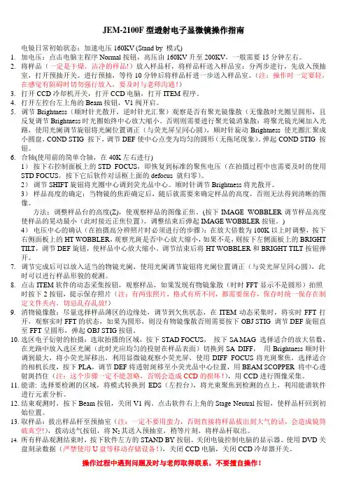
JEM-2100F型透射电子显微镜操作指南电镜日常初始状态:加速电压160KV (Stand by 模式)1.加电压:点击电脑主程序Normal按钮,高压由160KV升至200KV,一般需要15分钟左右。
2.将样品(一定是干燥,洁净的样品!)放入样品杆,将样品杆送入样品室:分两步进行,先放入预抽室,打开预抽开关。
进行预抽,等待10分钟后将样品杆进一步送入样品室。
(注:操作时一定要轻,在感觉有阻碍时切勿强行放入,要及时与老师沟通!)3.打开CCD冷却机开关,打开CCD电脑,打开ITEM程序。
4.打开左控台左上角的Beam按钮,V1阀开启。
5.调节Brightness(顺时针光散开,逆时针光汇聚)观察是否有聚光镜像散(无像散时光圈呈圆形,且反复调节Brightness时光圈始终中心放大缩小。
否则则需要进行聚光镜消象散:将聚光镜光阑加入光路,使用光阑调节旋钮将光阑位置调正(与荧光屏呈同心圆),顺时针旋动Brightness 使光圈汇聚成小圆盘,COND STIG 按下,调节DEF使中心点变为均匀的圆形(无拖尾现象)。
弹起COND STIG 按钮。
6.合轴(使用前的简单合轴,在40K左右进行)1)按下右控制面板上的STD FOCUS,即恢复到标准的聚焦电压(在拍摄过程中也需要及时的使用STD FOCUS,按下它后软件对话框上面的defocus 就归零)。
2)调节SHIFT旋钮将光圈中心调到荧光品中心。
顺时针调节Brightness将光散开。
3)样品高度的确定:当物镜的焦距确定后,随后就需要来确定样品的高度,否则无法得到清晰的图像。
方法:调整样品台的高度(Z),使观察样品的图像正焦。
(按下IMAGE WOBBLER调节样品高度使样品的晃动最小(此时接近正焦位置)。
调整结束后弹起IMAGE WOBBLER按钮。
)4)电压中心的确认(在拍摄高分辨照片时必须进行的步骤):在放大倍数为100K以上时调整,按下右侧面板上的HT WOBBLER,观察光斑是否中心放大缩小,如果不是,则按下左侧面板上的BRIGHT TILT,调节DEF旋钮,使样品中心放大缩小。
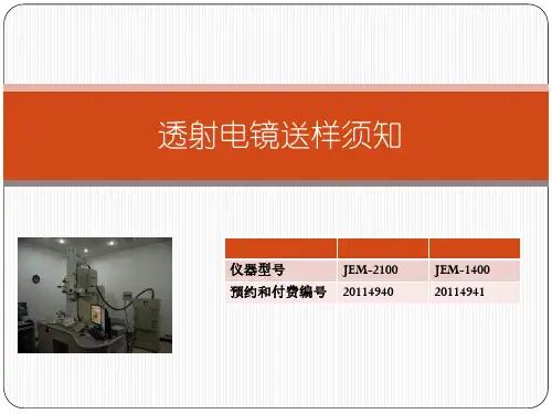
1400 电镜技术参数
电镜技术参数如下:
1. 分辨率:\~。
2. 加速电压:40kV\~120kV。
3. 电子枪类型:冷束电子枪。
4. 灯丝类型:钨灯丝或LaB6灯丝。
5. 放大倍数:10\~1,200,000。
6. 样品台:标配五轴马达驱动样品台。
7. 样品移动范围:X/Y,2mm;Z,1mm;最大倾斜角,±70度以上。
8. 功能特色:形貌测试(具备EDS,可做衍射,但目前不开放)。
9. 样品要求:3mm直径铜环承载样品,薄区在50\~100nm以内为佳;严禁磁性样品,不测;制样方法若为固体,选择FIB切样、离子减薄或电解双喷制备样品,若为粉末可选择溶解滴液制备样品于铜网上。
以上信息仅供参考,如需了解更多信息,建议查阅相关书籍或咨询专业人士。
JEM-100CXⅡ透射电镜操作说明一、开机程序1、首先打开房间空调,冷却循环水房温度21度,操作室25度2、开启冷却水循环装置,一个独立的小的控制器,先将开关打至ON,再将按下POWER键3、启动稳压电源,稳定于220V;查看电源箱供电指示灯亮4、用钥匙启动主机,从OFF档位旋到START位,松开后钥匙自动回到ON位置。
仪器自动抽真空,等待约40分钟。
5、直至DP绿灯亮,HIGH绿灯亮,READY绿灯亮(若不亮的话,将LENS LIGHT打至ON档位)。
二、电子枪合轴(1-3合轴)1、确认READY绿灯亮2、把样品拨出,物镜光栏拨出至0档位3、加高压:按下HT键后,依次按下40-60-80-100KV键,并注意观察束流表是否正常,每次都要等电流表显示稳定之后再进行下一步,一般调到80KV就行了。
4、加灯丝:将FILAMENT EMIISSION旋钮缓慢旋至锁定位置5、一般在SCAN(5300倍)条件下调节,调节CONDENSER钮,得到光斑。
6、SPOT SIZE调到3档,调节CONDENSER钮聚光,得到最小最亮光斑,然后用左右ALIGNMENT:TRANS(小的)将光斑拉至最中心位置(中心位置有一黑点)。
7、SPOT SIZE调到1档,调节CONDENSER钮聚光,得到最小最亮光斑,然后用GUNALIGNMENT:TRANS(X、Y)将光斑拉至中心位置。
8、再重复6、7步骤,使束流不偏离中心。
三、调灯丝相(每次开机都需要检查)1、在SCAN模式下,SPOT SIZE调到1档2、将FILAMENT EMIISSION旋钮稍稍往回调,到看到灯丝欠饱和像,即车轮像(鱼眼像),若车轮像不对称,则进行下面调节。
3、缓慢旋转GUN ALIGNMENT:TILT(X、Y),使灯丝像对称。
4、然后调节FILAMENT EMIISSION旋钮至灯丝饱和(即刚好全亮,没有阴影),并锁定该位置。
四、粗对焦(该步很重要)1、关灯丝(FILAMENT EMIISSION旋钮至OFF)后,插入样品,插入物镜光栏(2档)2、开灯丝(FILAMENT EMIISSION旋钮至ON)后,放大光斑至满屏(以免烧坏铜网)3、找到样品,并选中一目标为参照4、将IMAGE WOBBLER打至ON,此时看到样品会有一定的晃动,调节FOCUS旋钮(有大中小三个,一般只用到中和小)至图像清晰没有重影。
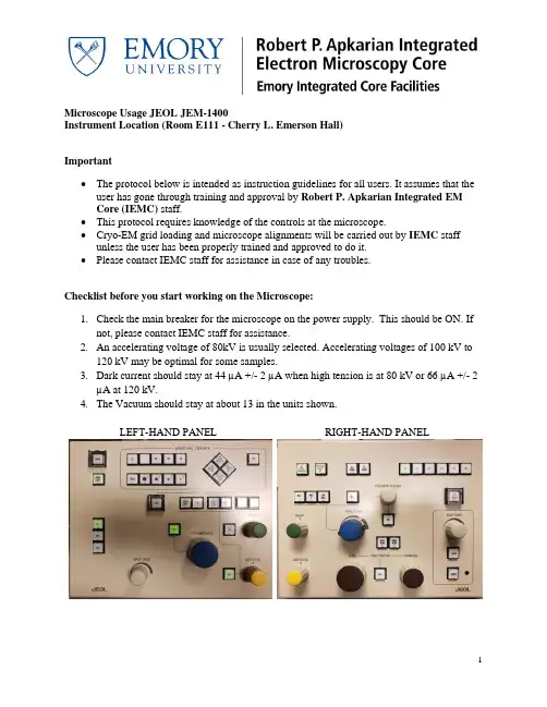
Microscope Usage JEOL JEM-1400Instrument Location (Room E111 - Cherry L. Emerson Hall)Important•The protocol below is intended as instruction guidelines for all users. It assumes that the user has gone through training and approval by Robert P. Apkarian Integrated EMCore (IEMC) staff.•This protocol requires knowledge of the controls at the microscope.•Cryo-EM grid loading and microscope alignments will be carried out by IEMC staff unless the user has been properly trained and approved to do it.•Please contact IEMC staff for assistance in case of any troubles.Checklist before you start working on the Microscope:1.Check the main breaker for the microscope on the power supply. This should be ON. Ifnot, please contact IEMC staff for assistance.2.An accelerating voltage of 80kV is usually selected. Accelerating voltages of 100 kV to120 kV may be optimal for some samples.3.Dark current should stay at 44 µA +/- 2 µA when high tension is at 80 kV or 66 µA +/- 2µA at 120 kV.4.The Vacuum should stay at about 13 in the units shown.LEFT-HAND PANEL RIGHT-HAND PANELTO INSERT THE SAMPLE INTO THE MICROSCOPE:1.The last user should have left the microscope at a magnification of 30Kx.2.ESSENTIAL: Reset the stage by selecting Control (C) then Stage then Stage Neutral.All stage coordinates (x, y, and z) in the stage panel should be close to 0.0. This is veryimportant and a value of 1.0 is already not acceptable.3.Lower the screen (press F1 on the right-hand panel), turn OFF the filament andmake sure that the objective lens aperture (OLA) is REMOVED. In case the OLAwas left inserted, please record this in the logbook.4.Check that the plug has been removed5.Insert the sample holder into the compustage by matching the pin to the opening and pushuntil you hear a valve open. At this point, the plastic flap of the holder is facing up.6.Move the Pump Switch to the UP position and watch for the vacuum value to go down onthe specimen chamber (to around 44 µA). A window will appear on the computer where the holder being inserted may be selected.7.Wait for the Evac Ready message (Green color) on the specimen chamber vacuumindicator on the Vacuum panel. The light over the pump switch will also become green when the vacuum is ready.8.Keep control of the holder during this step. Do not let it be pulled into the column freelyat any moment or the tip may be damaged.a.Turn the holder clockwise (short turn). As the holder goes into the microscope(short distance), hold onto it to guide it into the column and control the speed ofinsertion, don’t pull the holder, just let it go into the microscope as you hold it.b.Turn clockwise again (long turn) for a final, longer insertion. Do not let go of theholder until it is completely inserted. The holder’s plastic flag slides into itscorresponding opening on the compustage.9.Wait for the vacuum to be stable at ~13 units or below. This is immediate for roomtemperature but it may take about 5 to 10 minutes for cryo-EM samples.10.Turn on the filament and wait for the current to reach the set value automatically.GUN ALIGNMENT: done at 20Kx at the beginning of your session.10.Change the magnification to 20kx.11.Up to step 21, these alignments steps can be performed with or without a sample inserted.12.ESSENTIAL for the first user of the day: On the Alignment Panel, c lick on ‘Load.’Select the most recent engineer’s alignment file from the AlignmentData directory with the accelerating voltage that you wish to use (80 kV: alignment_80kv.jal; 120 kV:alignment_120kv.jal).a.In case the Alignment Panel is not visible: Select Control (C) on the menu andthen Alignment Panel (A).13.Click on Gun Align and change the Spot Size to 1 (knob on left-hand panel). Condensethe beam (make it brighter) by turning the Brightness knob on the left-had panel counter-clock wise. Center the beam using the green knobs on both panels (because Gun Align is selected, the green knobs are now assigned to Gun Align Shift).14.Click on Bright Tilt. Change the Spot Size to 5. Condense the beam into a spot with theBrightness knob and center it using the green knobs (now assigned to CL alignmentshift).15.Do steps 13 and 15 a few times until the beam stayscentered.16.Check that the Condenser Lens Aperture (CLA) isinserted. If not, insert it by turning the lever to theleft.17.Expand the beam as wide as possible to where youcan still see the edges on the fluorescent screen. Center the physical aperture manually using the CLA adjustment knobs (see picture).18.Depending on the sample type you will be imaging, select desired spot size for currentuse and center it.19.If beam is not round, press COND STIG on in the Alignment Panel. Make the beamround using the Brightness knob to change the size of the beam and the Yellow Knobs (now assigned to CL Stig) to adjust astigmatism.20.Press CL Stig again to deselect this option (or click on Cond Stig on the computerscreen).EUCENTRIC HEIGHT – to be done at the beginning and then for every new square:21.The eucentric height may be adjusted with the Z axis buttons (Z-up and Z-down), foundon the upper left of the right-hand panel or on the computer screen on the State panel.The speed of change for the Z height buttons can be adjusted in the Stage Panel. It hasthree settings: >,>>, and >>> for slow, medium, and fast.a.Find a noticeable, contrast-rich feature in the square.e the track ball (stage) to center the contrast-rich feature on the screen.ing the Stage Controller (-TX and +TX buttons), tilt the stage between 5 and 10degrees and watch the feature move away.ing the Z axis controls, change the Z height to where the feature comes back tothe center of the screen. Bring the tilt angle back to zero by clicking on the Tilt Xneutral button (Stage Controller window).e.Alternatively, press the Image Wobbler, X or Y. As the image wobbles, press theZ-up or Z-down button until the wobbling stops.22.Press the Standard Focus button located on the right-hand panel.INSERTION AND CENTERING OF OBJECTIVE LENS APERTURE (OLA)24.THIS STEP SHOULD NOT BE PERFORMED ONTHE CAMERA. ONLY ON THE FLUORESCENTSCREEN.25.Insert OLA, second largest aperture is generally suitable.In the picture on the right, the red dot is selectedmeaning that OLA aperture is NOT inserted.26.Select Diffraction (right-hand panel) to make the OLA visible.27.Center the objective aperture (OLA) with respect to the bright diffraction spot, using theknobs on the OLA control area.28.Press MAG1 to get out of diffraction mode and return to image mode.ADJUSTING OBJECTIVE STIGMATION.29.Find a contrast rich region on your grid. Start Digital Micrograph. Insert the US1000camera by clicking on Camera Inserted on the Camera Panel.30.Adjust brightness and turn on Obj Stig on the left-handpanel. Lift the screen with F1 and start the View onDigital Micrograph.e the Live FFT (Process – Live FFT) optionin Digital Micrograph and adjust the stigmator (yellow knobs) until a true rounddiffused halo is formed in the FFT.TO REMOVE THE SAMPLE FROM THE MICROSCOPE FOR SAMPLE EXCHANGE:31.ESSENTIAL:a.Turn the filament OFF.b.Center the stage by selecting Control (C) then Stage then Stage Neutral (the reddot moves to the center of the stage indicating that the stage has been centered.c.Remove the Objective Lens Aperture.32.The vacuum is quite strong so make sure to put a hand on the compustage to balance.33.Pull the sample holder out until the first stop and turn it counter-clockwise (long-turn).34.Pull the holder again (short distance) and turn it counter-clockwise (short turn). DO NOTPULL THE HOLDER ANYMORE35.Move the Pump Switch Down to the Air position. Wait for the airlock to be vented(vacuum to a ~200 µA value)36.Pull the holder out being careful not to hit the tip of the holder against the edge as it exits.TO END YOUR SESSION:37.ESSENTIAL:a.Turn the filament OFF.b.Center the stage by selecting Control (C) then Stage then Stage Neutral (the reddot moves to the center of the stage indicating that the stage has been centered.c.Remove the Objective Lens Aperture.d.Retract the Gatan CCD camera.38.Remove specimen holder as indicated in steps 32 to 36.39.Insert the blanking plug into the goniometer.40.Log your beam time in the notebook.SHUTTING DOWN THE JEOL 1400: END OF THE DAY ESSENTIAL TASKS41.Turn off the filament.42.Retract the Gatan CCD cameras. Be sure that both cameras are in the retract position.43.Center the stage by selecting Control (C) then Stage then Stage Neutral (the red dotmoves to the center of the stage indicating that the stage has been centered).44.Remove all apertures.45.Remove specimen holder.46.Insert the blanking plug into the goniometer.47.Insert and plug-in ACD heater into the LN2 ACD Dewar and select Control –Maintenance – ACD.48.When the microscope is shut off at the end of the day, make sure to leave it at 120 kVand a magnification of 30,000 x (30kx).49.When working with digital micrograph, please do not change the program settings.50.Conversion of .dm3 files to .tif is done using the ‘convert from display’ option instead of‘convert from image’.ALIGNMENT (VOLTAGE CENTERING).The Objective apertures must be out and the magnification set to 100kx.48.Spread and center the beam.49.Activate HT Wobb, found on right panel.50.Turn on Bright Tilt.51.Adjust Wobbling so that it is centered using the yellow knobs.52.Once achieved, deactivate all buttons used, i.e., HT Wobb and Bright Tilt.GAIN REFERENCE FOR THE GATAN CCD CAMERAS: Only to be done if permanent patterns are seen on the images.53.Find an empty grid square and adjust to a magnification of 20kx.54.Expand the electron beam so that it is extremely dim on the flu-screen.55.Flip the flu-screen up (using F1on the right-hand panel) and insert CCD (side mount:Orius or bottom mount: UltraScan).56.Acquire an image (full 2k frame, 1 s exposure).57.Select Analysis then Stat then Mean & SD.58.Reduce or increase the brightness of the image so that the count reads between 2000 and4000. The value to choose depends on the sample being imaged.1.To determine the count read one could position the cursor on the view windowand monitor the counts value on the Image Status panel (left side of the DigitalMicrograph Window; see Figure).59.In the Task Bar, select Camera then Prepare Gain Reference. Enter the average (MeanCounts value) into dialog box and press OK.60.When the counts become too bright during the gain reference acquisition procedure, thesoftware will ask to expand the beam so that the dose indicator moves to the greenintensity zone and to then press Enter.61.Repeat this procedure until the Gain Reference is acquired successfully.62.Remember that the beam is now expanded (dim). You will need to condense the beamback to the original brightness after Gain Reference acquisition.。
电镜使用方法说明书注意:以下是电镜的使用方法说明书,请仔细阅读并按照指示进行操作。
一、产品介绍:电镜(Electron Microscope,简称EM)是一种利用电子束来增大样品特征的科学仪器。
它具有高分辨能力和放大倍数,可用于观察微观结构,广泛应用于材料科学、生物学等研究领域。
二、安全须知:在操作电镜前,请务必了解以下安全须知:1. 请确保仪器连接正确的电源,并接地,以避免电击和其他安全事故;2. 严禁在潮湿环境下使用电镜;3. 请佩戴防护眼镜,在操作过程中避免直接接触电镜等部件。
三、操作步骤:1. 打开电源开关,并确保连接到仪器的计算机已经启动;2. 调节透镜,使图像清晰可见;3. 将待观察的样品装载到样品台上,并固定好;4. 调节样品到最佳的焦距;5. 使用电镜软件进行图像采集和处理,可以根据需要更换不同的放大倍数;6. 观察完毕后,将样品从样品台上取下,并关闭电镜和计算机。
四、常见问题与解决方法:1. 图像模糊:请检查透镜是否调节到最佳焦距,或者更换更高品质的样品;2. 电源无法启动:请检查电源是否连接正常,并确保电源开关处于打开状态;3. 电脑无法识别电镜设备:请检查连接电脑的USB线缆是否插紧,并重启计算机。
五、维护与保养:1. 在使用完电镜后,切记关闭电源开关,并将电镜与计算机断开连接;2. 定期清理电镜表面的灰尘和污渍,可以使用干净的软布擦拭,避免使用化学溶剂;3. 若电镜出现故障,请及时联系专业人员进行维修。
六、附录:本使用方法说明书仅适用于常规电子显微镜的操作,若使用其他型号或有特殊要求,请参考相应的使用手册。
感谢您使用本电镜,希望本说明书能够帮助您顺利操作电镜,获取到准确的观察结果。
如有任何疑问或需要进一步帮助,请随时联系我们的客服。
祝您工作顺利!。
JEOL JEM-1400Plus 性能说明及技术参数一、透射电镜性能说明JEM-1400Plus是一款拥有优秀成像和分析能力一体的高性能,高对比度,操作简便的最新型120KV透射电子显微镜。
加速电压从40KV到120KV可调,在继承具有广泛用户的JEM-1230/1400的特长的基础上,进一步在系统设计、电气设计、电子光学设计、样品台设计等方面升级的新一代120kV透射电子显微镜,广泛应用于生命科学、医学、高分子聚合物和各类材料研究领域。
JEM-1400Plus主要特点:对于低衬度样品有威力的高衬度成像光路、人性化操作系统升级、多功能扩张性、抗漂移性更强测角台,多项软件及功能升级等。
1.优秀的电子光学系统●更高衬度成像光路改进(HC极靴时)新设计的物镜系统可提供更高衬度的图象。
对低衬度的样品,如众多临床、免疫、药品、植物、食品、高分子材料的样品观察,JEM-1400Plus将发挥它显著威力。
同时改善后的电子光学成像性能更优,样品台稳定性更高,最高倍率x1,200,000倍。
●高衬度模式下的高分辨率(HC极靴时)JEM-1400Plus的验收分辨率直接在高衬度状态下进行,非常适合样品高衬度高分辨观察。
●冷束电子枪冷束电子枪是JEOL透镜的电子光学系统特长处,可提供更低灯丝电流下更高亮度、更好相干性的光源,其结果是灯丝寿命延长,样品损伤和污染减小,图象质量提高。
●预对中灯丝预对中钨灯丝,更换简单无需对中调整。
当选用六硼化镧(LaB 6 )预对中灯丝时,分辨率及衬度进一步提高。
●磁转角的修正和图象倾转系统JEM-1400Plus可在全倍率范围自动消除磁转角,并可在一定倍率范围内按要求进行图象倾转±90°。
更重要的是,在图象倾转后,JEM-1400还能允许用户自由变换放大倍数、相机长度,而图象和电子衍射花样均保持原来方向,样品的移动方向与图像的移动方向保持一致。
2.操作系统的智能化●人性化导航操作界面采用最新 Windows 7技术开发的操作界面,设备的状态、操作界面、CCD图象等巧妙融合,图象视野大。
JEM-200CX透射电镜使用说明操作要点1.双倾台严格使用φ3mm样品。
2.改变操作电压、更换样品时,应使灯丝束流降至OFF。
3.更换灯丝时,除特殊情况外,应两人以上在场,并尽量缩短安装时间。
4.每个操作者应为下一个操作者至少留10张未曝光底片,并保证予抽室中有待用底片;更换底片盒和装卸底片时必须带手套。
5.上机者不得随便更换束斑尺寸,不能变动B操作盘最右端旋钮;注意勿动各TILT钮;不许触动下列键:VACUUM SYSTEM下GUN 和COLUMN,EMERGENCY STOP,操作盘G中GUN LIFT。
6.更换灯丝后必须进行对中,以保证仪器处于良好的使用状态7.注意察看循环水流量。
8.详细填写工作记录,仪器出现故障要及时报告负责人。
9.使用空调机保持进气口过滤板的清洁。
操作规程一、开机程序1.确认下列开关和部位在正常位置:●READY 绿灯亮●AIRLOCK OPEN 绿灯亮●ACCELERATING VOLTAGE:HT--- OFF●FILAMENT EMISSION: OFF●物镜光栏位置---0●选区光栏位置---0●样品台倾转角---02.开机:●开启冷却水循环装置;●启动稳压电源,稳定于220V;查看电源箱供电指示灯亮;●用钥匙启动主机:从OFF位快旋到START位,松手后钥匙自动回至ON位。
等待约20分钟,仪器自动抽空(表现为:面板灯亮--压缩机工作--机械泵工作--水循环开始--真空系统DP绿灯亮--真空系统HIGH绿灯亮、READY绿灯亮)。
二、找电子束1.确认READY和AIRLOCK OPEN绿灯亮;2.样品台已插入镜筒;3.加高压:按下HT键后,80-100-120-160-200KV依次缓慢按键,并注意观察束流表指示是否正常,200KV下束流在95~115μA。
4.加灯丝:将FILAMENT EMISSION 钮慢旋至锁定位置。
在LOW MAG或MAG<1万倍下,调节大小CONDENSER钮,得到光斑。
JEM-1400操作维护方法一、日常使用1. 准备试样a)装试样入HOLDER(样品台),检查双O-RING。
放HOLDER入测角台,开始预抽真空;b) 将MONITOR调到真空图的页面,便于确认真空系统动作顺序;注意事项:●插拔样品时一定要小心!以免损坏样品、样品台●HOLDER插入测角台前,用HOLDER适当部位敲击手掌数次较好2. 升高压a) 确认高压READY;b) HT设定为60KV,HT ON;c)自动升高压,升压快慢自己掌握,以稳定、安全为基准;d) 确认暗电流正常。
3. 发射电子束(开Beam)a) 确认离子泵(SIP)和样品台预抽室的真空(绿灯亮否?),将HOLDER放入镜筒中;b) 确认Lens ON;c) 确认Beam Ready;d) 按下灯丝加热按钮,等待电子束发射稳定;e) 移动样品使得电子束能够到达荧光屏上;f) 寻找样品位置(LOW MAG下比较好找样品位置)。
4. 合轴(使用前的简单合轴)a) 必须过焦照明(用BRIGHTNESS顺时针散开);b) 确定物镜(OL)焦距(按一下STD FOUCUS);c) 样品高度的确定,方法:调整样品台的高度(Z),使观察样品的图像正焦。
(用Image Wobbler检查聚焦情况较方便);d) 电压中心的确认,按下HT WOBBLER,调节Beam Tilt使光同心收缩,在高倍下可利用样品作为参考,调节Beam Tilt使荧光屏中心黑点部分样品不动为最佳。
5. 物镜像散物镜像散调节的好坏直接影响到能否获得清晰的图像,通过利用CCD的傅立叶变换将圆环调圆。
6. 拍照使用CCD进行观察,调节物镜聚焦至正焦位置后进行拍照。
7. 使用结束后:关灯丝,降高压及关高压。
二、日常维护1.电镜室的环境要求a)温度:20±5摄氏度(变动小于1摄氏度)b)湿度:小于60%c)保持室内清洁2.换样品须知a)每天注意样品杆两个O形圈的清洁度,以及样品杆头部的清洁度;b)拧固定螺丝时,请选择合适大小螺丝刀且不要拧的太紧,以免损坏螺丝;c)放入样品前要确认样品装牢,检查橡皮圈,正确涂抹真空脂(应为白色的FOMBLIN);d)从测角台中拔出样品杆时,一定要把所有轴归零后再拔样品杆。
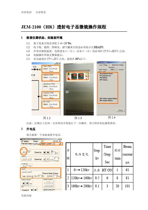
JEM-2100(HR)透射电子显微镜操作规程1检查仪器状态、实验室环境1.1离子泵真空度必须优于4×10⁻⁵Pa;1.2电子枪、镜筒、照相室、储气罐真空状态必须显示为READY;1.3冷却水箱的温度,包括进水口(左)、出水口(右)均必须在17.5℃~18.5℃之间;1.4电脑操作界面无警报提示;1.5室内温度在17℃~25℃之间,湿度在60%以下。
注意:出现以上任何一点异常均不得进行下一步操作,须立即告知仪器管理员。
2升电压每天做第一个实验前需升电压。
图1.2 图1.3 图1.4注意:升电压时必须注意Beam current 的稳定性,当每步完成时的Beam current 超过对应值(即高压箱放电)时,必须等Beam current 自我恢复到对应值并稳定一段时间才能进行下一步操作。
3 加液氮3.1加冷阱液氮每天第一次加冷阱液氮时必须分两次加,先加入少量(1/3瓶热水瓶)预冷,待冷阱温度稳定后再加满,此后每隔3~4个小时加一次液氮(直接加满)。
3.2加能谱仪液氮每隔1天加一次能谱仪液氮,此工作由电镜楼楼管负责,若能谱仪发出缺少液氮的警报声应立即告知楼管或仪器管理员。
注意:加液氮时观察屏的盖子一定要盖上,以防液氮腐蚀铅玻璃;操作面板也盖上塑料薄膜以防止液氮滴溅腐蚀按键。
4 装样、进样注意:任何通过该操作培训、考核的用户未经授权不得对其他用户进行培训,违者重罚。
5 加灯丝(发射电流) 点击Filament ON注意:加灯丝前须确保Beam current 在101μA 左右,离子泵真空度优于2×10⁻⁵Pa 。
冷阱能谱仪液氮罐6观察6.1普通形貌MAG1),6.1.2 放大倍数调至40K6.1.3 , 至图象不晃动;法二:6.1.4 聚焦(OBJ FOCUS6.1.5 ,聚焦后冻结后打开)6.1.6 保存图像6.2高分辨像6.2.1 检查电压中心:将放大倍数调至400K,光斑散开,按HT WOBB检查电压中心是否对中(图像有无左右上下晃动,有晃动则电压中心没有对中)。
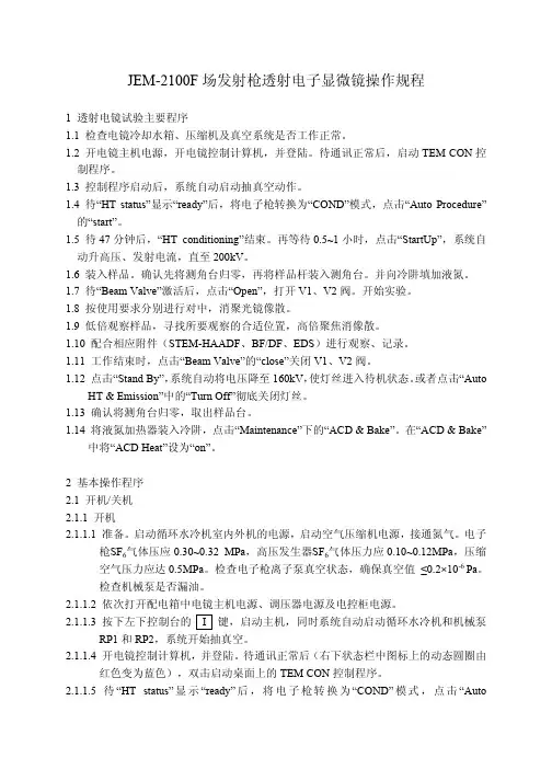
JEM-2100F场发射枪透射电子显微镜操作规程1 透射电镜试验主要程序1.1 检查电镜冷却水箱、压缩机及真空系统是否工作正常。
1.2 开电镜主机电源,开电镜控制计算机,并登陆。
待通讯正常后,启动TEM CON控制程序。
1.3 控制程序启动后,系统自动启动抽真空动作。
1.4 待“HT status”显示“ready”后,将电子枪转换为“COND”模式,点击“Auto Procedure”的“start”。
1.5 待47分钟后,“HT conditioning”结束。
再等待0.5~1小时,点击“StartUp”,系统自动升高压、发射电流,直至200kV。
1.6 装入样品。
确认先将测角台归零,再将样品杆装入测角台。
并向冷阱填加液氮。
1.7 待“Beam Valve”激活后,点击“Open”,打开V1、V2阀。
开始实验。
1.8 按使用要求分别进行对中,消聚光镜像散。
1.9 低倍观察样品,寻找所要观察的合适位置,高倍聚焦消像散。
1.10 配合相应附件(STEM-HAADF、BF/DF、EDS)进行观察、记录。
1.11 工作结束时,点击“Beam Valve”的“close”关闭V1、V2阀。
1.12 点击“Stand By”,系统自动将电压降至160kV,使灯丝进入待机状态。
或者点击“AutoHT & Emission”中的“Turn Off”彻底关闭灯丝。
1.13 确认将测角台归零,取出样品台。
1.14 将液氮加热器装入冷阱,点击“Maintenance”下的“ACD & Bake”。
在“ACD & Bake”中将“ACD Heat”设为“on”。
2 基本操作程序2.1 开机/关机2.1.1 开机2.1.1.1 准备。
启动循环水冷机室内外机的电源,启动空气压缩机电源,接通氮气。
电子枪SF6气体压应0.30~0.32 MPa,高压发生器SF6气体压力应0.10~0.12MPa,压缩空气压力应达0.5MPa。
JEM2010型透射电镜开机操作:MAG 放大倍数Current density 束斑电子密度Exp time 曝光时间Specimen 样品位置,尽量让X Y接近0,但在+/- 100均可以。
Brightness 束斑大小(旧:condenser)Shift 光斑平移(旧:Aignment-trans)Spot size 1—4 或1—5 合轴(旧:1—3 合轴)Object focus 物镜聚焦1.开循环水。
由于新电镜循环水不关,这步可省。
但要注意水温是否正常。
2.打开电源开关。
IN/OUT。
从来都是开着的,这步也可省。
3.打开荧屏电源;检查荧屏第一页:确认①电压是否在120KV;如不是,请联系值班老师;②确认样品位置“specimen position”为原点:<x,y,z>=0,0,0,如果不是原点,使用观察窗左侧“SPEC CONTROLLER”控制面板上的N键复原(注意在没有插入样品杆时,严禁使用“N”键!,所以每次推出样品杆之前应该复位);③α-selector 为24.用键盘键入P3,使荧屏显示第三页,检查P1-至P5的电流值,正常情况下:p1:25,p2:25,p3:29,p4,28,p5,100,观察阀V1,V2和V4, V5B, V8, V13,V17和V 21共8个阀处于打开状态。
5.察看右下方的真空面板,确定真空进入10-5Pa量程,理想的状态的是指针居中,在灌入液氮的情况下应该更低;如没达到这个范围,请联系值班老师;6.灯丝处于关闭状态(filament的开关ON没亮)7.检查聚光镜光栏是否全打开,物镜光栏是否全打开,如不是请打开全部光栏。
检查右侧面板,观察电镜是否处于MAG1(此灯亮)8.打开左侧门,将“lens”开关打到ON的位置(请一定要非常小心,确认是lens开关,不要开错开关。
即开灯丝,将开关稍向外拉再抬上即开。
)。
9.再次观察荧屏,电压是否在120KV,如果不是,严禁进行下面操作。
COMPACT MANUAL FOR GI USERS OF THE JEM 1400 FLASH BEGINNERS (For internal use only) Gray means additional information at the end of this mini-manualABOUT THIS MICROSCOPE (room HG01.240)The JEM-1400Flash (Jeol, Nieuw-Vennep, Tokio) is a widely applicable transmission electron microscope, that can produce high quality images, while it is still relatively easily to operate.Applications comprise a wide range of fields, such as biology and materials studies, including nanotechnology and polymer research. The microscope can be employed for mappingoverviews as well as for detecting fine structures (theoretically up to a 0.2 nm resolution) at high magnification. The JEM-1400Flash is routinely operated at 120 KV and its electronsource is a LaB6 crystal. A powerful feature is the high-sensitivity Matataki Flash sCMOSbottom-mounted camera, that allows a high frame-rate acquisition of extremely sharpimages with a very low readout noise. In addition to the conventional electromagnetic image shift, the JEM-1400Flash comes with a montage system capable of utilizing stage drive forthe field shift. This new system allows the simple capture of a montage panorama imageover a limitless wide area at high resolution (Limit Less Panorama LLP software). ForCorrelative Light and Electron Microscopy (CLEM) workflows a digital image acquired with an optical microscope can be overlaid on a TEM image through an Optical Microscope Linkage function.BEFORE STARTING1.Get instructions from Geert-Jan Janssen(http://www.ru.nl/science/gi/about_us/who_is_who/)2.Book the microscope on Bookings.science.ru.nl(How to book: http://www.ru.nl/science/gi/about_us/online-booking/)STARTING THE PC3.In principle, the PC is always on. If not, switch it on.4.Windows login (left mouse click):Choose the default for standard use. That is name: beginner; password: beginner (smallfonts).5.Wait until the TEM Center software has finished to initialize6.Choose the specimen holder. Standard is “Specimen quick change holder”. OK7.In principle the HT (High tension) is on (should be green) and the vacuum is low enough tostart operation.8.If vacuum or HT are not ready, the HT icon on the screen will appear in gray. You can try toswitch on the HT by a double click on the icon. The HT should start to raise. Wait until HTvoltage is 120 kV. If the HT does not reply, warn Geert-JanLOADING OF THE GRID INTO THE HOLDER9.The sample holder should have been stored on the dedicated stand10.Open the storage case with the holder11.To load the grid on the specimen (=sample) holder, clutch the top and bottom of thespecimen fastening leaf spring at its clip end from front with a pair of tweezers. The lip will open.12.Remove any forgotten/left grid from the specimen retainer. Place a new grid with theobservation side facing upward in the retainer.13.To close the specimen fastening leaf slowly move the fastening leaf clip towards its endusing tweezers. It is important that this fastening leaf spring is well closed. If not, the spring will be damaged inside the goniometer). So check that the clip end is completely flat!1 Goniometer2 Objective diaphragm3 Left panel4 Tracking ball5 Viewing screen with cover6 Right panel7 High-voltage cable8 Electron gun9 Condenser apertureINSERTION OF THE HOLDER INTO THE COLUMN14.Make sure that there is no dust and/or lint on the specimen holder o-ring. Do not touch theholder with your naked fingers in the area between o-ring and tip, as any grease or dirt may contaminate the high vacuum.15.To insert the holder in the goniometer, follow these steps (see diagram on next page):1. Align the specimen holder guide pin with the guide groove on the goniometer and pushuntil stop (Figure 1)2. Set the goniometer PUMP/AIR switch to PUMP (Figure 2) by gentling pulling the metalswitch and flipping it upwards to PUMP position. The yellow lamp (Figure 2) lights up, and evacuation of air from the goniometer begins. Wait for a green lamp!3. When the green lamp lights (the yellow lamp is still on), gently turn the holder clockwiseuntil stop.4. The holder will be pulled in for a small distance.5. Turn completely clockwise until stop6. allow it to be pulled as far as it will go (do this with care, for example by slowing down theprocess with your forefinger (Figure 2)). The yellow lamp goes off16.Confirm specimen holder in software popupCREATE A PROJECT17.In the TEM Center menu bar select File > New project.18.In the popup “ “Create a project” enter the following information:Project name:Example YearMonthDay-lastname-experiment#-sequence, like 20180122-Janssen-23-002 Select a destination folder on the F drive for this project.Project root folder: F: > INSTITUTE > Department > UserInstitutes can be: DCN, IMM, IWWR, OTHER, GI19.Connections with USB sticks or external hard drives are not allowed, because of the risks ofvirus infection and spreading.This F drive on the PC is only a temporary location for your data. Therefore data should be uploaded at the end of each session and removed from the F drive within 1 month. Datastored for a longer period can be removed by the staff without prior notification. You areresponsible for the storage and backup of your own data.20.Recommended settings for DataFiling:Select folder for saving the images (F is the dedicated data drive): F: > Institute >Department > UserIn File Naming Rules set the file name of the image to save by defining it with help of thefollowing buttons (click to activate: becomes green)Instrument: JEM-1400Operator: enter name of operator/studentMag button: adds magnification factorSpecimen: enter a –repetitive- specimen nameFree text: ….Date Time: …Sequence number: incrementalOption: free text can be enteredFile format: 2048 px x 2048 pxPANELS LAYOUT IN BEGINNER CONFIGURATION21.Atthe bottom of the left window of the TEM Center software choose the Configuration called“Beginner”. It attributes the following functions to the left and right panel and the trackball:1 Screen up2 Exchange holder3 Standard focus4 MAGnification5 LOW MAGnification6 MAGNIFICATION7 IMaGe WOBBler8 Z FOCUS9 FOCUS10a Y deflector knob10b X deflector knob11 Capture12 Auto Focus13 Beam Shift14 Leave as it is(Pressing this button changes the function of the MULTIFUNCTION button 15)15 MULTIFUNCTION button. The attributed function is Spot size16 Brightnesst1 Trackballt2 Superfinet3 CoaRSet4 ShiftLOW MAGNIFICATION ORIENTATION22.In the popup screen “HT Beam Condition” double click on the icon Beam Ready. The signBeam on flashes. Wait until the icon Beam on is stable green!23.Remove the black cover from the glass window on the chamber with the phosphorescentviewing screen24.Press LOW MAG ( Right panel 5): images in the range 10x to 1000x van be viewed.25.Remove the Objective diaphragm out of the beam path by turning its handle towards thefront26.Warning: Always keep the illumination beam evenly spread over the phosphorescent screenby adjusting it with the Brightness knob (Left panel 16) (Note: the brightness knob steers the condenser lens).27.To check and adjust the centering of the beam, do not fully expand the beam so that itsmargin remains visible. Then use the x and y deflectors (10b and 10a) to move the beam toa centered position. When ready, fully expand the beam to the viewing edge using theBrightness knob. The sample is optimally illuminated.28.Search Region of Interest (ROI) on the grid using the trackball (t1) and position it in thecenter of the green viewing screen. While moving and/or zooming in or out (usemagnification 6 on the right panel), continue to check the illumination beam and adjust the brightness.IMAGING AT VARIOUS MAGNIFICATIONS29.Insert an objective diaphragm into the beam path by turning the handle depicted herebelow towards the rear position.30.Press Mag (Right panel 4) to adjust the magnification (not too high at once). Beam nicelyspread using brightness knob (16)! The beam should never appear as a very intense spot,because the camera could be damaged.31.Recommendation: in order to retain the proper brightness settings in other magnifications,the Brightness MAG Link can be activated (or check that it has been activated = green). This menu can be accessed by click on Illumination next to TEM in the Illumination System popup (see here below)32.When a desirable ROI has been identified, move to the camera (a Matataki Flash sCMOScamera) by pressing Screen up (Right panel 1). Put the black cover over the opening of theglass window of the viewing chamber. The Bottom Mount Camera Life Image shows thecurrent field of view in life mode.33.Now the z focus of the holder height can be adjusted (you can see the changings in your liveimage) by pressing Standard Focus (Right panel 3) one time (the button briefly lights up); this action clears the defocus.34.Press Image Wobbler (Right panel 7). With the image wobbler the electron beam is rapidlytilted alternatively in slightly positive and slightly negative direction with respect to theoptical axis the deflected beam produced an alternating slightly shifted image (doubleimage) when the holder is not positioned in the exact eucentric plane. When the objective lens is focused exactly on the specimen plane, no change in the image is apparent.35.Press Z focus (Right panel 8) an orange labeled popup appears and z-focus is assigned to Z-focus 9.36.Turn Focus knob 9 (Right panel) until the two projections of the wobbler function coincideand the image becomes still.37.Press Image wobbler (7) and z-focus (8) outHOW TO OPTIMIZE THE CONTRASTIdeal focus has the lowest contrast, as the electron magnetic waves are then best in phase.To enhance contrast in your images, apply light defocus.38.Slightly defocus by turning focus knob 9, but the image should remain sharp.39.Before capturing images, go to the popup DataFiling and set the exact path and format inwhich to save them.40.Open the extension menu of Capture (double arrows on right side); a popup called Otheropens below the window called Capture.Choose preferably the option Center.Adjust the Brightness with knob 16 until the arrow of the Signal Indicator is positioned in the green region. This exposure generates a well-balanced histogram more or less in the central part of the 16 bits range ( intensity values [0, 65535]).In case of an unevenly stained or contrasted sample, ask Geert-Jan advise to optimize themode of exposure.Standard settings for the camera (Do not change these settings, because of risks of over-exposure of the camera and risks of damage! In case of doubts on the settings, always askGeert-Jan for advise).41.and in the folder on the beginner login desktop that explains the 16 bit tiff information. 42.To acquire an image, click on Single Capture (the icon becomes green) A window with thecaptured image is displayed. (Options: double click and scroll to zoom in. it is possible to add comments). The captured image is automatically saved in the project.(Recommended is Tiff (16bit) and Jpeg High.43.For consistency and comparison of results it is recommended to take always the samemagnification steps during multiple session, (e.g. not once X 1000, X 10 k and X 40 k, andanother time X 800, X 9 k and X 32 k).44.There are options for panorama imaging. Single views can be stitched to one large field.HOW TO CLOSE A SESSION OR CHANGE A SAMPLE45.When ready, click twice on the button Exchange holder (2 in right panel). Doing soengenders the following actions:Electron beam off: Check that Beam is OFF (gray) under HT/Beam conditionStage x, y and z is moved in the exchange position for the selected holderThe viewing screen is moved downThe camera id shut down automaticallyA beep can be heard when done.HOW TO REMOVE THE HOLDER46.1. Pull out the holder completely.2. Turn counter clockwise until stop3. Pull until stop (Short distance)4. Turn counter-clockwise until stop5.Set the metal switch to AIR. Yellow and green lamp goes off.6. Wait for 30 seconds before removing the holder (the ventilation sound of the gonio-chamber can be heard)HOW TO REMOVE THE GRID AND STORE THE HOLDER47.Set the holder on the stand of the storage case and remove the grid with EM tweezers(Sameprocedure to open the spring like in HOW TO INSERT A GRID INTO THE HOLDER).48.Fully close the spring (should be completely flat)49.Slide the protective tube over the tip50.Close the cover of the storage case to protect the holder from dust and dirt.51.Store it in the appropriate cupboard52.Cover the vieuwingscreen with the black coverUPLOAD TOUR DATA ON YOUR SERVER AND SIGN OUT53.Exit TEM Center54.Upload your images from the D drive to your own server. See options on the GeneralInstrumentation webpage: http://www.ru.nl/science/gi/about_us/server-services/ or seethe prints dedicated to Connections to external servers in the blue folder with help menus in the room of the TEM 140055.When ready, disconnect the server56.Sign out from Windows under user57.Switch off both screensADDITIONAL INFORMATIONnthanum hexaboride (LaB6): https:///wiki/Lanthanum_hexaboride59.Matataki Flash sCMOS camera: 2048 x 2048 px, Readout noise 0.9 electrons (median),dynamic range 33000 : 1, 16 bit, USB 3.0, TIFF, BMP, JEPG.60.There is a folder at the beginner login desktop with some files to download(Magnification table. Fiji macro etc.)。
JEM-1400透射电子显微镜在纳米材料测试中的应用
韩沐昕;李冬梅;赵晟锌
【期刊名称】《中国现代教育装备》
【年(卷),期】2024()3
【摘要】以JEM-1400透射电子显微镜为例,介绍了透射电镜的基本结构、工作方式、电子光学成像原理及分辨率、放大倍率等基本概念,探讨了影响纳米材料样品高质量成像的因素及对策。
从灯丝高度及束流强度调试方面讨论了提高材料样品分辨率的可行性:基于灯丝像,通过调节灯丝饱和度和偏压,使灯丝发射量达到15μA;在保证灯丝寿命的前提下,分辨率从过去的200 nm提高到10 nm以下。
【总页数】4页(P26-28)
【作者】韩沐昕;李冬梅;赵晟锌
【作者单位】黑龙江建筑职业技术学院;哈尔滨工业大学环境学院
【正文语种】中文
【中图分类】TN16;G434
【相关文献】
1.透射电子显微镜与选区电子衍射对纳米材料的联合分析
2.先进的电子断层扫描技术在材料科学中的发展——基于透射电子显微镜和扫描透射电子显微镜
3.透射电子显微镜在纳米生物学实验教学中的应用
4.树脂包埋在透射电子显微镜测试中的应用
因版权原因,仅展示原文概要,查看原文内容请购买。
不同保存时间的血浆及血清中外泌体生物学特性的对比王婷婷;韩影;高芳芳;叶磊;张育军【摘要】目的外泌体对于疾病的诊断和治疗具有不可比拟的优势,但其保存方法、保存时间、保存效果的评估研究较少.文章旨在观察不同保存时间的血浆及血清中外泌体的大小、密度、形态及阳性蛋白表达有无改变.方法使用Exoquick试剂盒分别提取新鲜及保存在-80℃冰箱1年、3年、5年的正常人血浆及血清中的外泌体;使用纳米粒度颗粒跟踪分析仪对提取的外泌体进行粒径分析;使用透射电镜对提取的外泌体的形态进行观察;Western blot检测外泌体标志物TSG101和CD63的表达改变.结果保存时间达3年的血浆中的外泌体粒径较大(30~200 nm),血清较血浆中外泌体数量略高;电镜下不同保存时间的血浆及血清中外泌体形态变化不明显;随着保存时间的延长,血浆及血清中外泌体蛋白TSG101及CD63含量发生降低,其中CD63降低尤其明显.结论不同保存时间的血浆及血清中外泌体粒径及形态变化差异不大,但其内含蛋白标志物随着时间延长发生明显减少,因此进行外泌体蛋白的相关研究时推荐新鲜提取立即实验.【期刊名称】《医学研究生学报》【年(卷),期】2019(032)007【总页数】5页(P705-709)【关键词】外泌体;血清;血浆;保存【作者】王婷婷;韩影;高芳芳;叶磊;张育军【作者单位】100044北京,北京大学人民医院消化内科;100044北京,北京大学人民医院中心实验室;100044北京,北京大学人民医院中心实验室;100044北京,北京大学人民医院中心实验室;100044北京,北京大学人民医院中心实验室【正文语种】中文【中图分类】R550 引言外泌体(exosomes)是由细胞向细胞外主动分泌的具有典型磷脂双分子层结构的一种囊泡,其大小介于30~200 nm之间[1-2]。
外泌体内含有细胞来源的各种蛋白质、核酸及脂质分子,在细胞-细胞间物质传递及信息交流具有重要作用,参与了多种疾病的发生[3-4],外泌体亦可作为药物载体及疾病的治疗靶点[5]。
JEOL 1400 TEMUser GuidePrior to getting started1.Turn on Monitors 1 and 22.Login to EMU server at Monitor 23.At Monitor 1, open the “TEM Centre” software4.Make sure that “HT On” & “Beam Ready” are displayed in the HT/Beamcondition window5.Open Beam Controller window from Control menu•Beam (dark) current should indicate:•~44uA for 80kV•~55uA for 100kV•~65uA for 120kV6.If HT is off, no beam current is displayed or you want to work at a higheror lower kV than that indicated, please seek help from Jenny, Sigrid orKatieLoading a specimen1.Remove the specimen holder from the microscope:•Pull out in a straight line until it stops•Turn anti-clockwise until it stops•Pull out again for a short distance•Turn anti-clockwise until it stops•Pull out toggle switch and flip to AIR•Wait 10 sec then remove holder from the microscope2.Remove the specimen cartridge from the specimen holder•Hold specimen cartridge with blunt forceps•Insert levering rod into hole on specimen cartridge fastening jaw •Raise the jaw by gently tilting the levering tool backward3.Insert grid into specimen cartridge•Use levering rod to hold back end of specimen cartridge down •Use blunt forceps to lever up the brass specimen retainer •Place a grid specimen side up into the retainer•Again use the levering rod to hold the specimen cartridgedown•Use blunt forceps to clip thebrass specimen retainer closed •The brass specimen retainershould lie completely flat whenclosed4.Reattach the specimen cartridge to the specimen holder•Hold the specimen cartridge withthe blunt forceps•Insert the levering rod into thehole on specimen cartridgefastening jaw•Raise the jaw by gently tilting thelevering tool backward•Align the guide hole over the guidepin and close jaw5.Insert specimen holder into microscope column•Align guide pin with grove•Push specimen holder in until it stops (donot turn yet)•Pull out toggle switch and flip to PUMP,orange LED will illuminate•Wait until green LED illuminates (~ 1min)•Turn specimen holder clockwise until itstops (small turn)•Guide holder as it is drawn into themicroscope column•Turn clockwise until it stops (larger turn)•Very gently guide the holder into its finalpositionGenerating an electron beam1.Confirm that “HT On” and “Beam Ready” are displayed in the HT/Beamcondition window•Beam (dark) current should indicate:~44uA for 80kV, ~55uA for 100kV or ~65uA for 120kV •If HT is off and no beam current is displayed, please seek help from Jenny, Sigrid or Katie2.At top of left hand control panel press BEAM and wait until blinking stops3.Turn the brightness knob to see if an electron image appears on screen•If no electron image can be seen, move the specimen in case you are situated over a grid bar•If you still can’t see an electron image, seek staff assistance4. A good starting point for getting underway is:•Condenser aperture 2 (second largest dot)•Press LOW MAG•Remove objective aperture by turning anti-clockwise to the red dot•Locate region of interest on grid and centre to screen•Introduce objective aperture 2 (second largest dot)•Press MAG 1•Spot size set to 25.Centre the beam using the gun shift X and gun shift Y knobs6.Begin imagingFocusing using the wobbler1.Roughly focus the image through the binocular head2.Press IMAGE WOBB X or Y3.Adjust the OBJ FOCUS knob so that the image stops oscillating and thedouble image is unified4.Press IMAGE WOBB X or Y again to deactivateTaking digital images using “DIGITAL MICROGRAPH” software The digital camera can be damaged by the bright flash that occurs during changes to magnification. Please only insert the camera to take an image then remove again to move around the specimen or adjust image magnification.1.Set the desired image magnification, focusthe image and spread the beam to achievea uniformly bright image2.Insert the digital camera3.In the Camera View box, check that theCamera Inserted box is ticked and that theAuto Exposure box is ticked4.Click on Start View•If you need to change image magnificationclick on Stop View and remove the digitalcamera from the microscope column•Reintroduce digital camera and click onStart View again5.In the Camera Acquire box, check that theAuto Exposure box is ticked6.Click on the Tools icon in the bottom rightcorner7.Check that Full CCD is selected8.Check that Auto Exposure isselected and that Connectionsis set to Gain Normalisedually Binning 1 is ok10.Good resolution can be obtainedby setting Frame Sum to 4 •The specimen must not bedrifting otherwise the 4 frameaveraged image will be out offocus•If specimen drift is an issue reduce the number of frames tobe averaged11.The Gatan image file format is dm3. To save images as tif or jpg go toFile, Save display as, and name the file. When prompted, choose: actual resolution, include annotations (to save scale bar) and save as grey scale.Specimen exchange1.If specimen has been tilted during imaging, open STAGE CONTROLwindow from CONTROL menu and click STAGE NEUTRAL2.At top of left hand control panel press BEAM and wait until blinking stops3.Remove specimen holder from microscope column as described previously4.Load new grid into specimen cartridge5.Reload specimen holder into microscope as described previously6.Press BEAM and wait until blinking stops7.Begin imagingAt end of session1.Minimise microscope magnification2.If specimen has been tilted during imaging, open STAGE CONTROLwindow from CONTROL menu and click STAGE NEUTRAL3.Ensure digital camera is retracted and Stop View has been selected4.At top of left hand control panel press BEAM and wait until blinking stops5.Remove specimen holder from microscope column as described previously6.Remove grid from specimen cartridge7.Reload specimen holder into microscope as described previously8.To ensure your images are archived, copy them to a folder underJeol1400 in the Images folder of the EMU samba server (M drive)9.It may be worthwhile to also save a copy to your User folder on the Mdrive10.Logoff the EMU Server11.Turn both monitors offAdvanced Users NotesOptimising the electron image Changing the objective apertureThe objective aperture has a significant effect on image contrast andresolution. The smaller the aperture, the higher the image contrast but the darker the image. We have 20um, 40um, 60um and 120um aperturesselectable.•Insert a specimen into the beam path•Ensure an objective aperture is inserted•Press DIFF on the right hand control panel•Using DIFF FOCUS knob, focus to create bright spot on screen•Centre bright spot using DEF/STIG X and Y knobs•Press PLA and focus for smallest spot using BRIGHTNESS knob•Centre the spot using SHIFT X and Y•Select desired objective aperture•Focus the aperture image usingthe DIFF FOCUS knob•Adjust aperture knobs A and B sobright spot is in the centre of theaperture•When done, press DIFF and PLAto deactivate and return to normalimagingChanging the condenser apertureThe condenser aperture controls the illumination area, angle and brightness.The smaller the aperture, the higher the image quality but the darker the image. We have 100um, 200um and 300um apertures selectable.•Adjust the brightness knob for the smallest beam spot•Centre the beam spot to the screen using SHIFT X and Y•Insert the desired condenseraperture•Slowly turn the brightness knobclockwise•If the beam moves off centre,re-centre it using the condenseraperture knobs A and B•Ensure electron beam convergesand diverges centrally throughBRIGHTNESS focusCorrecting condenser lens astigmatism•Adjust the BRIGHTNESS knob for the smallest electron beam•Press COND STIG•Slowly turn BRIGHTNESS knob back and forth through focus•Use DEF/STIG X and Y knobs to make electron beam round rather than elliptical at either side of focus•Press COND STIG again to deactivateDiffraction Mode•Turn the BRIGHTNESS knob to darken the image sufficiently•Press the DIFF switch•Adjust the MAG/CAML knob to choose the desired camera length•Adjust the DIFF FOCUS knob to obtain the sharpest diffraction pattern•Press MAG 1 to return to normal imagingImaging difficulties•If the microscope imaging system is misaligned•Press IMAGE SHIFT, then NTRL•Press PLA, then NTRL•Press COND STIG, then NTRL•Press OBJ STIG, then NTRL•Press DARK TILT, then NTRL•Press BRIGHT TILT, then NTRL•This reloads the default settings optimised during installation Emergency Shutdown•In an emergency, open the narrow panel on the right side under the desktop console•Press the EM-STOP switch•Notify a staff member immediately。