YSF8压力释放阀说明书
- 格式:pdf
- 大小:9.78 MB
- 文档页数:12
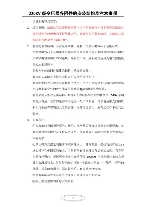
一、油浸纸电容式套管;1.适用范围;油纸电容式变压器套管(以下简称套管)用于变压器出线导体穿过外壳起绝缘和支持导体之用,套管在变压器安装时,其轴线与垂线间的角度最大不超过300。
2.套管的主要结构;套管是由油枕、瓷套、法兰及电容芯子连接组成。
主绝缘电容芯子是由绝缘纸和铝箔电极在导电管上卷绕而成的同心圆柱形串联电容器用以均匀电场,经真空干燥、浸油处理后成为电气性能极高的油纸绝缘体。
瓷套为外绝缘同时还作为保护主绝缘的容器。
套管的头部油枕上设有油位表可以指示油位变化。
套管的中间设有供安装连接用的法兰,法兰上设有供变压器注油时放出变压器上部空气的放气阀及测量套管tgδ的测量引线装置。
套管采用全密封金属结构,其内部充以经特殊处理的优质的10GBX尼纳斯变压器油,套管的电容芯子完全不与大气相通。
可以避免阳光的照射和大气中的有害物浸入套管内部,而使绝缘老化。
所有连接件不受气候影响。
3.安装程序;①安装前应查清套管型号、代号、规格是否符合订货单的使用要求,按装箱单查看零附件及文件是否齐全,检查套管在运输过程中有无损伤及渗漏现象。
②以正确方式把包装箱水平放在地面上,打开箱盖,把挂钩挂在法兰凸缘的吊环孔中固定绳吊具,当吊具附有撑板时应有足够的长度,当套管在垂直位置时,撑板至少应高出套管顶部600mm把提绳滑轮安装在撑板中心或吊钩上,并在套管由枕与第一个瓷扇之间加上一条绳,(套管的重量、吊车的选用上)固定好滑轮、套管提出包装箱。
彻底地清洁套管安装法兰的底面,接地部分及下瓷套。
③按正确位置将均压球安装到位。
④变压器引线装置;把接线板(引线接头)应固定在变压器输出端,注意密封圈不要遗忘。
在安装引线接头时,用细绳足够力的拉线穿入套管中心管并用这根线把引线接头的M12螺栓连接。
⑤把引线接头安装到变压器输出端的未端上,并彻底清洁引线接头表面和变压器引线清洁变压器升高座顶部表面的密封垫、并固定其位置,检查套管的法兰及下瓷套是否完全清洁和擦干。

OZB.469.504安装使用说明书-35kV级油浸式变压器中电电气集团江苏中电输配电设备有限公司目录35kV级油浸式变压器安装使用说明书1.适用范围 (1)2.变压器结构简介 (1)3.运输 (2)4.验收 (2)5.存放 (2)6.安装变压器 (2)7.变压器投入运行 (5)8.变压器投入运行后的注意事项 (5)附录组件使用说明A.压力释放阀 (6)B.分接开关 (8)C.套管 (14)D.吸湿器 (15)E.温度控制器 (16)F.气体继电器型 (18)G.SYJ-50型速动油压继电器 (20)H.指针式油位计 (22)35kV级油浸式变压器安装使用说明书1适用范围1.1本说明书适用于35kV级油浸式变压器。
1.2产品型号说明S F S Z9-□/□高压绕组电压等级(kV)额定容量(kVA)性能水平代号调压方式:有表示有载调压,无表示是无励磁调压绕组数:有表示三绕组,无表示双绕组冷却方式:有表示风冷,无表示自冷三相变压器2变压器结构简介2.1铁心铁心材料选用优质高磁导冷轧取向硅钢片,全斜,步进式三级接缝,无孔绑扎,板式夹件结构。
2.2线圈线圈材料采用优质无氧铜材料制造的圆铜线或扁铜线,低压线圈采用连续式或螺旋式结构;高压线圈采用连续式或多层圆筒式,不浸漆,但经过干燥处理形成一个有机整体。
2.3器身绝缘铁心窗口内线圈上端增设30mm整体层压木压圈及30mm分体附压板,下端增设70mm整体层压木托板,不但加强了主绝缘强度,而且提高了线圈轴向的动稳定性。
2.4引线高压引线,有载调压时采用优质的有载调压分接开关,无励磁调压小电流时采用无励磁调压分接开关,大电流时采用三只单相无励磁分接开关。
2.5油箱≤6300kVA变压器采用桶式油箱和固定式片式散热器,≥8000kVA变压器采用钟罩式油箱和可拆卸式片式散热器。
2.6总装配压力释放阀开启式变压器容量≥315kVA安装压力释放阀(见附录A)。
温度控制器变压器容量≥1000kVA安装温度控制器(见附录E)。
YSF压力释放阀YSF Pressure release valve使用说明书Instructions沈阳市金钟电器厂Shenyang Jinzhong electrical appliance factoryYSF Pressure release valve带防护罩的YSF4,5型压力释放阀定向喷油螺纹安装的YSF6型压力释放阀With a protective hood Specify the direction of Spray oil , Thread Installed定向喷油法兰安装的YSF7型压力释放阀定向导油法兰安装的YSF8,9型压力释放阀Specify the direction of Spray oil , Flange Installation Specify the direction of Oil Guide,Flange Installation YSF7 Pressure release valve YSF8,9 Pressure release valve- 1 -二, 型号、规格与基本技术参数Models, specifications and basic technical parameters:1, 型号Model :Y S F / D(S)KJTHB压力释放阀Pressure release valve 型号举例Model example: YSF 5 –55 / 130 D(S)KJTHBYSF 代表压力释放阀, 5 代表设计序号, 55 代表开启压力, 130 代表有效口径,YSF On behalf of pressure release valve,5 Serial number of Design,55 Opening pressure,130 Effective aperture D ( S ) 代表开关数量单( 双 ), K 代表电信号, J 代表机械信号, TH 代表湿热带地区,B 代表闭锁装置 D(S) -Switch amount one(two), K -Electric Signal, J - Mechanical signal, TH -Humid Tropics, B-Locking Device 2, 使用条件:-30℃至+100℃ 如遇寒带地区,采用特殊密封圈可满足-45℃Exploitation conditions -30℃ to +100℃ In case the frigid zone area, uses the special seal packing collar to be possible to satisfy -45℃3, 基本技术参数Basic technical parameters :有效口径Effective aperture (mm) 开启压力Opening pressure(KPa)关闭压力(不小于)Close Pressure (Not less than)(KPa)∮25∮5015±58 25 13.5 35 19 55 29.5 ∮80 ∮1303519 55 29.5 70 37.5 85 45.5 13874.5三, 带有电信号的输出接线线路图With electrical signal output wiring circuit diagram:a, 单开关接线线路图 b, 双开关接线线路图 C,双开关接线线路图Single-switch Two-switch Two-switch wiring circuit diagram wiring circuit diagram wiring circuit diagram信号开关接点容量Signal switch contact capacity :AC 220V 5A DC 220V 0.3A(电阻负载Resistive load )- 2 -。

YSH55-8580-130型压力释放阀使用说明书西安西变组件有限公司1.适用范围压力释放阀使用与油浸式变压器等电气设备,用于释放变压器油内部过压力的一种保护装置,当油箱内部压力升高至压力方法的开启压力值时,在2ms内迅速开启,使得油箱内压力很快降低,当降低至阀的关闭压力值时,阀门又可靠关闭,油箱内保持正常压力。
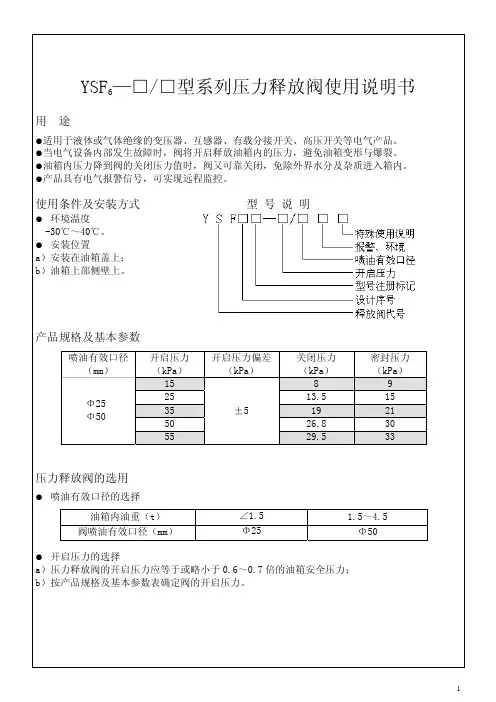
2产品型号编制办法2.1型号组成:Y(压力)S(释放)F(阀门)□(设计序列号)-□(开启压力kPa)/□(配有口径mm)KJ(带信号开关和机械信号)□(特殊环境代号)(注意:特殊环境代号:干热带地区“TA”;湿热地区“TH”;干、湿热带地区2.2型号举例:YSF1-55/130KJTH适用于湿热带地区的配有口径为130mm,开启压力为55kPa,带信号开关和机械信号装置、第一次设计的压力释放阀。
3.基本参数(见表1):表1开启压力35 55 70 85开启压力偏差±5关闭压力不小于19 29.5 37.5 45.5密封压力不小于21 33 42 514、结构和工作原理:4.1 压力释放阀的主要结构型式是外弹簧式,并可带或不带定向导流装置,它的主要部件由弹簧、阀座、弹簧座、阀壳体(罩)、标志杆、信号开关(出现盒)、密封圈等零部件组成。
4.2工作原理压力释放阀是用来保护油浸式变压器等电气设备过压力保护的安全装置,可以避免变压器油箱变形或爆裂。
当油浸式变压器内部发生事故时,油箱内的油被气化,产生大量气体,使得油箱内部压力急剧升高。
此压力如果不及时释放,将造成油箱变形或爆裂。
安装压力释放阀就是当油箱内压力升高到压力释放阀的开启压力时,压力释放阀在2ms内迅速开启,使得油箱内的压力很快降低。
当压力降到压力释放阀的关闭压力值时,压力释放阀又可靠关闭,使得油箱内永远保持正压,有效地防止外部空气、水气及其他杂质进入油箱;在压力释放阀开启同时,标志杆向上动作且明显伸出顶盖,表示压力释放阀已动作过,在压力释放阀关闭时,标志杆仍滞留在开启后的位置上,然后必须由手动才能复位。
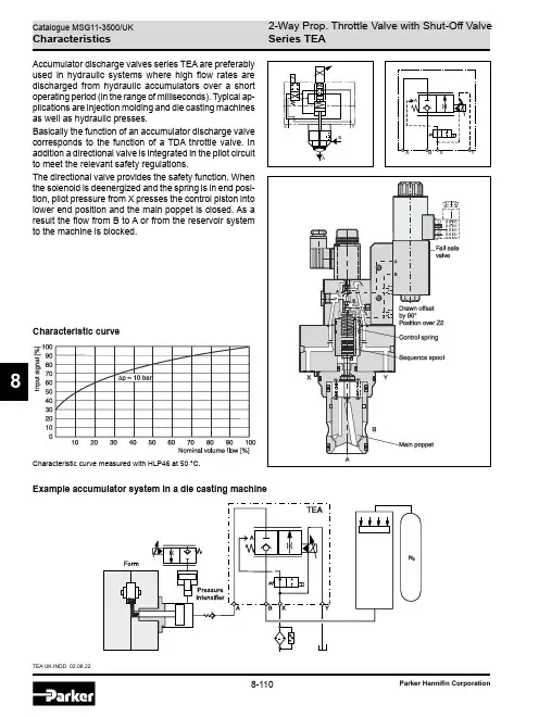
8-110TEA UK.INDD 02.08.228Parker Hannifin CorporationExample accumulator system in a die casting machineAccumulator discharge valves series TEA are preferably used in hydraulic systems where high flow rates are discharged from hydraulic accumulators over a short operating period (in the range of milliseconds). Typical ap-plications are injection molding and die casting machines as well as hydraulic presses.Basically the function of an accumulator discharge valve corresponds to the function of a TDA throttle valve. In addition a directional valve is integrated in the pilot circuit to meet the relevant safety regulations.The directional valve provides the safety function. When the solenoid is deenergized and the spring is in end posi-tion, pilot pressure from X presses the control piston into lower end position and the main poppet is closed. As a result the flow from B to A or from the reservoir system to the machine is blocked.Characteristic curveCharacteristic curve measured with HLP46 at 50 °C.8-1112-Way Prop. Throttle Valve with Shut-Off Valve Series TEATEA UK.INDD 02.08.228Catalogue MSG11-3500/UKParker Hannifin CorporationOrdering Code / Technical DataOrdering codeTechnical dataPlug socket withoutplugSolenoid voltage Seals Design series(not required for ordering)Code Seal N NBR VFPMProp. solenoid voltage Code Proportional solenoid voltageL 6 VDC X 16 VDCCodeSolenoid J 24 V= / 1.25 A U 1)98 V= / 0.31 A G 1)205 V= / 0.15 A 1) To be used in combination with rectifier plugs at 120 VAC / 230 VAC power supply.8-112TEA UK.INDD 02.08.222-Way Prop. Throttle Valve with Shut-Off Valve Series TEA8Catalogue MSG11-3500/UKParker Hannifin CorporationDimensionsTEA NG25 (50)TEA NG63 (100)。
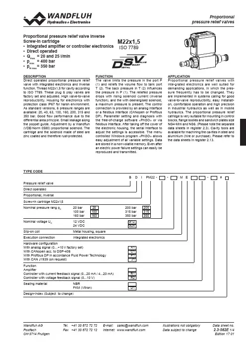
Wandfluh AG Tel. +41 33 672 72 72 E-mail: ******************Illustrations not obligatoryData sheet no.PostfachFax +41 33 672 72 12 Internet: Data subject to change 2.3-562E 1/4 CH-3714 Frutigen Edition 17 01TYPE CODEB D IPM22 --/ M E-#Pressure relief valve Direct operated Proportional, inverse Screw-in cartridge M22x1,5Nominal pressure rang p N 20 bar 20 200 bar 200 100 bar 100 315 bar 315160 bar 160 350 bar 350Nominal voltage U N 12 VDC G1224 VDCG24Slip-on coilMetal housing, square Execution connectionIntegrated electronicsHardware configurationWith analog signal (0…+10 V factory set)A1With CANopen acc. to DSP-408C1With Profibus DP in accordance Fluid Power Technology P1With CAN J1939 (on request) J1Function AmplifierController with current feedback signal (0...20 mA / 4...20 mA) R1Controller with voltage feedback signal (0...10 V) R2Sealing material NBRFKM (Vitron)D1Design-Index (Subject to change)Proportional pressure relief valve inverse Screw-in cartridge• Integrated amplifier or controller electronics • Direct operated• Q max = 20 and 25 l/min • p max = 400 bar • p N max = 350 barDESCRIPTIONDirect operated proportional pressure relief valve with integrated electronics and inverse function. Thread M22x1,5 for cavity according to ISO 7789. These plug & play valves are factory set and adjusted. High valve-to-valve reproducibility. Housing for electronics with protection class IP67 for harsh environment. As standard versions, 6 pressure ranges are available: 20, 40, 63, 100, 160, 200, 315 and 350 bar. Good flow performance due to the differential area principle. Small leakage along the poppet guide. Adjustment by a Wandfluh (VDE-Norm 0580) proportional solenoid. The cartridge and the solenoid made of steel are zinc coated and therefore rust-protected.FUNCTIONThe valve limits the pressure in the port P (1) and reliefs the volume flow to tank port T (2). The back pressure in T (2) influences the pressure in P (1). The reliefed pressure drops with rising solenoid current (inverse function), and the with deenergised solenoid, a maximum pressure is present. The control connection is provided by an analog interface or a fieldbus interface (CANopen or Profibus DP). Parameter setting and diagnosis with the free-of-charge software «PASO» or via fieldbus interface. After taking off the cover of the electronic housing, the serial interface to adjust the settings is accessible. The menu controlled Windows program «PASO» allows easy adjustment of all variable settings. Data are stored in a non-volatile memory. Even after an electric power failure settings can easily be reproduced and transmitted.APPLICATIONProportional pressure relief valves with inte-grated electronics are well suited for demanding applications, in which the pres-sure frequently has to be changed. They are implemented in systems calling for good valve-to-valve reproducibility, easy installati-on, comfortable operation and high precision in industrial hydraulics as well as in mobile hydraulics. The proportional pressure relief catridge is very suitable for mounting in control blocks, flange bodies and sandwich plates size NG4-Mini and NG6. (Please note the separate data sheets in register 2.3). Cavity tools are available for machining the cavities in steel and aluminium (hire or purchase). Please refer to the data sheets in register 2.13.M22x1,5ISO 7789Wandfluh AG Tel. +41 33 672 72 72 E-mail: ******************Illustrations not obligatory Data sheet no.Postfach Fax +41 33 672 72 12 Internet: Data subject to change 2.3-562E 2/4CH-3714 FrutigenEdition 17 01SYMBOL37s3M22x1.5T(2)X1X2X4 (nur Regler)(controller only)35.583X1X3X225,30501821, 2240706s613M DELECTRICAL SPECIFICATIONSProtection class IP 67 acc. to EN 60 529with suitable connector and closedelectronics housingSupply voltageRampsParameterisationInterfaceAnalog interface:Mating connectorPreset value signalFieldbus interface:Device receptaclesupply (male)Mating connectorDevice receptacleCANopen (male)Mating connectorDevice receptacleProfibus (female)Mating connectorPreset value signalFeedback signal interface (Sensor):(controller only)Device receptacle (female) M12, 5-polesMating connector Plug (male), M12, 5-poles(not incl. in delivery)Feedback signal:: Voltage / current state when orderingCONNECTOR WIRING DIAGRAMAnalog interface:Supply voltage +Supply voltage 0 VDCStabilised output voltagePreset value voltage +Preset value voltage -Preset value current +Preset value current -Reserved for extensionsReserved for extensionsEnable control (Digital input)Preset value voltage (PIN 4/5) resp. current (PIN 6/7) are selected withV), (PIN 4/5)Parameterisation interface (USB, Mini B) X2Under the closing screw of the housing coverFeedback signal interface (Sensor)Device receptacle (female) X4 (only controller)1 = Supply voltage (output) +2 = Feedback signal +3 = Supply voltage 0 VDC4 = not connected5 = stab. output voltage2 = Reserved for extensionsDevice receptacle Device receptacleCANopen (male) X3 Profibus (female) X3CAN PROFIBUS1 = not connected 1 = VP2 = not connected 2 = RxD / TxD - N3 = CAN Gnd 3 = DGND4 = CAN High 4 = RxD / TxD - P5 = CAN Low 5 = Shield31452123543145212354123451234123431452HYDRAULIC SPECIFICATIONSFluid Mineral oil, other fluids on requestContamination ISO 4406:1999, class 18/16/13efficiency (Required filtration grade ß 6…10≥75)see data sheet 1.0-50/2Viscosity range 12 mm2/s…320 mm2/sFluid temperature -20…+70°CPeak pressure pmax= 400 barNominal pres. ranges pN= 20 bar, 100 bar, 160 bar, 200 bar,315 bar, 350 barMin. volume flow Qmin= 0,1 l/minMax. volume flow Qmax= 25 l/min for pN=20 bar / 100 bar /160 bar / 200 barQmax= 20 l/min for pN= 315 barQmax= 5 l/min for pN= 350 barLeakage volume flow see characteristicsRepeatability ≤ 3 %Hysteresis ≤ 5 %GENERAL SPECIFICATIONSDescription Direct operated proportional pressure reliefvalve with integrated electronics inverse functionConstruction Screw-in cartridge for cavity acc. to ISO 7789Operations Proportional solenoid wet pin push type,pressure tightMounting Screw-in thread M22x1,5Ambient temperature -20…+65°C (typical)(The upper temperature limit is a guideline value for typicalapplications, in individual cases it may also be higher or lower.The electronics of the valve limit the power in case of a toohigh electronics temperature. More detailed information can beobtained from the operating instructions «DSV».)Mounting position any, preferably horizontalFastening torque MD= 50 Nm for screw-in cartridgeMD= 5 Nm for knurled nutWeight m = 1,0 kgWandfluh AG Tel. +41 33 672 72 72E-mail: ******************Illustrations not obligatoryData sheet no.PostfachFax +41 33 672 72 12 Internet: Data subject to change 2.3-562E 3/4 CH-3714 FrutigenEdition 17 01CHARACTERISTICS Oil viscosity υ = 30 mm 2/s p = f (Q) Pressure volume flow characteristics (Maximum adjustable pressure)p= f (Q) Pressure volume flow characteristics (Minimum adjustable pressure)Q L = f (p)Leakage volume flow characteristicsp red = f (l) Pressure adjustment characteristics[at Q = 10 l/min] / (s corresponds to preset value signal)p = f (l) Pressure adjustment characteristics [at Q = 5 l/min] /(s corresponds to preset value signal)NOTE!Detailed electrical characteristics and description of «DSV » electronics are shown on data sheet 1.13-76.START-UPFor DSV amplifiers as a rule no parameter settings by the customer are required. The plugs have to be connected in accordance with the chapter «Pin assignment».Controllers are supplied configured as amplifiers. The setting of the mode of control and the setting of the controller are done by the customer by software setting (USB interface, Mini B).Additional information can be found on our website:«»Free-of-charge download of the «PASO»-software and the instruction manual for the «DSV » hydraulic valves as well as the operation instruc-tion CANopen eg.Profibus DP protocol with device profile DSP-408 for «DSV ».NOTE!The mating connectors and the cable to adjust are settings is not part of the delivery. Refer to chapter «Accessories».Factory settings:Dither set for optimal hysteresis= Deadband: Solenoid switched offwith command preset value signal <5 % p Nmechanicallly pre-set at Q = 5 l/min= Limited pressure in port P (1) at 70 % of preset value signal: 95 bar with pressure range 350 bar 65 bar with pressure range 315 bar 56 bar with pressure range 200 bar 32 bar with pressure range 160 bar 25 bar with pressure range 100 bar 4 bar with pressure range 20 bar0 10 20 30 40 50 60 70 80 90 100s [%]p [bar]4003002001000 10 20 30 40 50 60 70 80 90 100s [%]p [bar]1209060300p = f (l) Pressure adjustment characteristics [at Q = 5 l/min] / (s corresponds to preset value signal)40030020010000 5 10 15 20 25Q [l/min]p [bar]N = 200 bar N = 160 bar N = 100 bar N= 20 bar504030201000 5 10 15 20 25Q [l/min]403020100 50 100 150 200 250 300 350 p [bar]Q [cm 3/min]0 10 20 30 40 50 60 70 80 90 1001251007550250I [%]p [%]Wandfluh AG Tel. +41 33 672 72 72 E-mail: ******************Illustrations not obligatoryData sheet no.PostfachFax +41 33 672 72 12 Internet: Data subject to change 2.3-562E 4/4 CH-3714 Frutigen Edition 17 01Cavity drawing according to ISO 7789–22–02–0–98For detailed cavity drawing and cavity toolssee data sheet 2.13-1003With fieldbus interface Amplifier With fieldbus interface ControllerDIMENSIONS / SECTIONAL DRAWINGS*Adjusting screw for setting the nominal pressure (-20 % / +30 %)With analog interface Amplifier and ControllerACCESSORIES • Cartridge built in:flange and sandwich bodies see register 2.3• Set-up softwaresee start-up• Cable to adjust the settings through interface USB (from plug type A to Mini B, 3 m) article no. 219.2896• Cable connector for analog interface: – straight, soldering contact article no. 219.2330 – 90°, soldering contact article no. 219.2331Recommended cable size: – Outer diameter 9…10,5 mm – Single wire max. 1 mm 2 – Recommended wire size: 0…25 m = 0,75 mm 2 (AWG18) 25…50 m = 1 mm 2 (AWG17)Technical explanation see data sheet 1.0-100PARTS LIST Position Article Description17160.2187O-ring ID 18,72 x 2,62 (NBR)18160.2170O-ring ID 17,17 x 1,78 (NBR)20154.2700Knurled nut21223.1317Dummy plug M16 x1,522160.6131O-ring ID 13,00 x1,525062.0102Cover square 30072.0021Gasket 33,2 x 59,9 x 240208.0100Socket head cap screw M4 x1050160.2188160.6188O-ring ID 18,77 x 1,78 (NBR)O-ring ID 18,77 x 1,78 (FKM)60160.2140160.6141O-ring ID 14,00 x 1,78 (NBR)O-ring ID 14,00 x 1,78 (FKM)70049.3177Back-up ring RD 14,6 x 17,5 x 1,4353790.2s 30M 22x 1.5T(2)X2X1X3X4172.4P(1).5(1)E: Venting。

YS-6、60、250、600活塞式压力计说明书一、用途0.05级活塞式压力计(以下简称压力计)、用于检验0.2级活塞式压力计及精密压力表二、工作原理与基本结构压力计的工作原理基于活塞本身重量和加在活塞上的专用砝码重量,作用在活塞面积上所产生的压力与液压容器内产生的压力相平衡。
压力计系由检验泵和测量系统两部分组成。
见图:检验泵部分包括手摇泵(11)、油杯(9)及两个阀(6)和(7)。
在阀(6)和(7)上装有两端锁母,用以连接被检验的精密压力表。
测量系统主要由一个经过精密研磨后具有精确截面的活塞,活塞直接承受底盘上的砝码重量。
三、技术数据表1精确度等级基本误差限压力值在测量范围下限以下时压力值在测量范围内时0.02 测量范围下限的±0.02% 实际测量压力值的±0.02%0.05 测量范围下限的±0.05% 实际测量压力值的±0.05%YS-250、600活塞式压力计的承重杆(包括活塞头部)浸入工作液体浮力为5.6g.YS-6活塞式压力计,活塞底部与被校表中心液柱差H,表壳外径为φ150㎜,H=109㎜;表壳外径φ160㎜,H=119㎜,表壳外径φ250㎜,H=169㎜,其修正公式△P=Hγ,式中△P为液柱差产生的压力,γ=0.88g/cm3为变压器油的比重。
1、砝码2、指标板3、底座4、调整螺钉5、连接管部件6、7、8阀9、油杯10、水平仪11、手摇泵12、手轮13、测量系统参数单位值力值0.6MPa 6 MPa25MPa60 MPa测量上限MPa0.66256060测量下限MPa0.040.10.511活塞公称面积cm210.50.20.10.05底盘及活塞公称质量㎏0.40.5110.5产生产压力MPa0.040.10.511专用砝码公称质量㎏0.1;0.5 0.5;2.5 1;51;50.5;2.5产生的压力MPa0.010.050.010.50.5;2.51;51;5数量个6;104;114;94;111;11两端锁母M20×1.5M20×1.5M20×1.5M20×1.5M20×1.5重量㎏3565859575工作液体变压器油20℃时运动粘度9~12厘沲酸值不大于0.5毫克KOH/克癸二酸酯20℃时运动20~25mm2/s,酸值不大于0.05毫克KOH/克四、验收与保管1、用户收到装箱压力计,应先检查压力计包装是否完整;如有损伤,应即查明原因。
压力释放阀PRESSURE RELEASE VALVE使用说明书OPERATION INSTRUCTION明远电器设备SHENYANG MINGYUAN ELECTRIC EQUIPMENT CO., Ltd.本说明书适用于我公司生产的系列变压器用压力释放阀,阐述其用途、性能、规格、技术参数、使用及安装,供用户参考。
The Operation Instruction is applicable to pressure release valve of a series of transformers manufactured by our company, indicating its application, performances, specifications, technical parameters, usage and installation for uses’ reference.1. 压力释放阀用途和性能压力释放阀适用于油浸式电力变压器、电力电容器及有载分接开关等,用来保护油箱。
当油浸式变压器在运行中出现故障时,由于线圈过热,使一部分变压器油汽化,变压器油箱中压力迅速增加,这时压力释放阀在2ms迅速动作,释放压力,保护油箱不致变形或爆裂。
油箱的压力再升高而达到开启压力时,压力释放阀应再次动作,直到油箱的压力降到正常值。
由于压力释放阀动作后能可靠关闭,油箱外的水和空气不能进入油箱,变压器部不会受大气污染。
1.Application and performancePressure release valves play a vital role in the protection of oil-immersed electrical equipments, such as transformers, high voltage switch gears, capacitor and on load tap-changers, etc. This device can prevent the oil-immersed electrical equipment from deformation or rupture. Should a fault occur in such electrical equipment, from deformation of rupture? Should a fault occurring in such electrical equipment, they are instantaneously vaporize the oil causing extremely rapid build-up of gaseous pressure? If mounting this type pressure release device on the oil-tank, when the pressure reaches to its opening pressure, it opens automatically within 2ms and relieves the pressure.2.型号、规格及基本参数Type, specification and technical parameters2.1 型号的含义 Meaning of typeY S F□—□ / □□□特殊环境代号(Special environment)带机械信号标“J”(“J”:mechanical signal)带信号开关标“K”(“K”:electrical signal)两者都带标“KJ”(“KJ”:Both with signal)喷油有效口径(Caliber of oil-gushing tube)mm开启压力(Opening pressure)kPa设计序号(Design serial number)阀(valve)释放(release)压力(pressure)注:特殊环境代号 note: special environment:TA: 干热带地区 dry tropicTH: 湿热带地区 humid tropicT: 干、湿热带地区 dry、humid tropic例:YSF16-55/130KKJT开启压力为55kPa,喷油口径为φ130mm,带电信号、机械信号。
20KV级及以下油浸单相柱上式配电变压器安装使用说明书中华人民共和国浙江格林电气有限公司目录1.20KV级及以下油浸单相柱上式配电变压器安装使用说明书………………………………………()2.无励磁分接开关使用说明书………………………………………()3.压力释放阀安装使用说明书………………………………………()20KV级及以下油浸单相柱式配电变压器安装使用说明书1.本说明书适用于20KV级及以下的油浸单相柱上式配电变压器。
2.变压器到货后,须立即按下述各项进行检查,并做记录,以便及时发现问题追查原因。
(1)按变压器铭牌数据查对变压器是否与合同相符。
(2)按变压器“出厂技术文件一览表”查对所到的技术文件,图纸等是否齐全。
(3)检查变压器主体有无渗漏油现象。
3.起吊与搬运变压器:(1)起吊变压器,应使两个吊拌同时受力。
(2)起吊时吊绳与垂线之夹角应小于30°。
4.变压器在搬运过程中,变压器倾斜角度不得超过15°,当符合投入运行条件的规定时变压器可不吊芯检查,装配有关拆卸的零部件,做验收试验项目,合格后,便可投入运行。
对不吊芯检查变压器的要求:5.变压器不拆卸运输,即可做投入运行前的试验项目。
6.在补注变压器油时,须注意补注变压器油型号,产地或油基,不同型号的变压器油一般不得混合使用,或混合须试验合格后方可使用。
7.取变压器油样,并做试验。
从油箱下的活门(或球阀)取出抽样。
进行化验分析:(1)油的击穿电压数值:油的击穿电压>35KV。
(2)油介质损失角在90°C时,小于0.1%。
(3)每克油中油的酸值小于0.03毫克。
(4)闪点不低于140°C。
(5)油中应无机械混合物、游离碳、水份等。
油质不符合上述规定时,应进行过滤处理;以达到合格要求。
8.如果变压器发生事故时,事故后必须取油样进行化验。
9.在温度不低于10°C时,进行下列试验:(1)测量线圈所有分接位置的直流电阻,应符合出厂时的数据,注意出厂时数据为75°C时的直流电阻。
变压器压力释放阀、气体继电器吸湿器等设备的作用及维护摘自本人撰写的《余热(下册)》一、变压器压力释放阀的作用是什么?YSF系列压力释放阀是用来保护大中型油浸式变压器的压力保护装置,在变8压器内部故障产生大量气体时,可以避免油箱变形和爆裂。
该装置采用定向喷油方式,避免了大范围喷油和污染。
该装置内部设有一个信号开关,其常开接点在装置开启喷油时闭合,将压力释放信号送入变压器非电量保护装置(NDSBT-300),在发出事故信号的同时,跳开变压器两侧开关。
该装置的开启压力为55Kpa(该压力系变压器油箱安全压力的0.6~0.7倍);关闭压力为34Kpa。
二、变压器压力释放阀应该进行哪些维护与试验?应该利用电气设备检修的机会,对压力释放阀进行以下维护与试验:1.清除阀内异物;2.密封圈是否老化、变形或损坏;3.零部件是否锈蚀、变形或损坏;4.信号开关动作是否灵活可靠;5.开启、关闭动作是否灵敏,如有卡堵现象应排除。
三、气体继电器的保护原理?气体继电器是油浸式变压器内部故障的一种主要保护装置,该继电器安装在变压器与储油柜的连接管路上。
在变压器内部发生轻微故障时,绝缘油分解产生的气体积聚在继电器上部的气室内,迫使其油面下降,开口杯(浮子)随之下降到一个限定位置,固定在开口杯上的磁铁使干簧接点吸合,接通信号回路,发出报警信号。
若由于变压器缺油或其它原因使油面下降,同样会动作于信号回路,发出报警信号。
在变压器内部发生严重故障时,油箱内压力骤然升高,绝缘油将会出现涌浪,使油流急剧流向储油柜冲动继电器内部的挡板,当挡板旋转到一个限定位置时,固定在挡板上的磁铁使干簧接点吸合,接通跳闸回路,瞬时跳开变压器两侧开关,从而起到保护变压器的作用。
四、气体继电器的取气盒有什么作用?气体继电器安装在变压器与储油柜的连接管路上,安装位置高、且距离高压引线较近,所以巡视检查、取气、排气非常不便,并且不安全。
生产厂家将取气盒安装在主变外壳距地面1.5~1.7米高的位置,使用配套的连接导管,将气体继电器的取气出口与取气盒的取气进口紧密连接后,取气盒就成为气体继电器的一个外接气室。
GRUNDFOS说明书PRVPressure relief valves安装和使用说明书Other languages/qr/i/96681525中文 (CN)2中文 (CN) 安装和使用说明书翻译原来的英文版这些安装与操作指导对格兰富PRV(泄压阀)进行了说明。
章节1-4介绍了以安全的方式安装和启动本产品所需的信息。
章节5-10介绍了有关产品的重要信息,以及有关服务、故障查找和产品处置的信息。
目录页1. 概述1.1 目标人群本文档适用于运营公司和用户。
在产品安装前以及产品操作和检修过程中必须遵守本手册中规定的一般安全说明。
负责人员在对产品进行任何操作之前必须阅读这些说明。
1.1.1 资格和培训负责本文档所述任务的人员必须具有相关资质。
1.1.2 运营公司的义务•遵守地方安全规章。
•请始终在安装地点放置安装与操作指导,以供随时查阅。
•按照章节9.技术参数的说明协调安装位置的准备。
•确保用户经过针对相关任务的培训。
•提供规定的安全设备和个人防护设备。
•安排定期维护。
1.1.3 用户责任•遵守公认的健康和安全规定以及本地事故预防规定。
•在操作产品和处理化学品时,按照当地健康和安全规定穿戴防护装备。
•阅读并理解本文档。
1.2 安全运行如果阀门已经无法保证安全运行,必须将产品从系统中解除并保证不会被意外地再次用于运行。
以下情况属于上述说明:•产品出现明显可见的损坏。
•如果产品看起来无法操作。
•在恶劣的条件下存放了较长的时间。
1.概述21.1目标人群21.1.1资格和培训21.1.2运营公司的义务21.1.3用户责任21.2安全运行21.3本文献中所用符号32.安装产品32.1位置32.2机械安装32.2.1安装要求32.2.2安装示范32.2.3泄压阀高达460 l/h 42.2.4泄压阀DN 6543.调试产品43.1设置泄压压力43.1.1最佳安装53.1.2其他安装54.搬运和储存产品54.1搬运产品54.2储存产品55.产品介绍55.1设计用途55.1.1不恰当的操作方法55.2型号55.2.1铭牌(泄压阀从60到460 l/h)55.2.2型号66.维护产品76.1维护日程76.2清洁处理76.3更换隔膜77.配件77.1联接螺母适配器(高达460 l/h)77.2用于泄压阀DN 65的一组对接法兰78.故障查找89.技术参数89.1允许介质温度89.2存放温度与环境温度89.3泄压阀高达60 l/h 89.3.1技术参数89.3.2材料89.3.3尺寸图89.4泄压阀从60到460 l/h 99.4.1技术参数99.4.2材料99.4.3尺寸图99.5泄压阀DN 65109.5.1技术参数109.5.2尺寸图1010.产品废弃10开始安装前,请先阅读本文件。