压力释放阀使用说明书(沈阳金钟)
- 格式:pdf
- 大小:328.11 KB
- 文档页数:5
![压力释放阀说明书[中英]](https://uimg.taocdn.com/2e96aecc76c66137ef06192d.webp)
压力释放阀PRESSURE RELEASE VALVE使用说明书OPERATION INSTRUCTION明远电器设备SHENYANG MINGYUAN ELECTRIC EQUIPMENT CO., Ltd.本说明书适用于我公司生产的系列变压器用压力释放阀,阐述其用途、性能、规格、技术参数、使用及安装,供用户参考。
The Operation Instruction is applicable to pressure release valve of a series of transformers manufactured by our company, indicating its application, performances, specifications, technical parameters, usage and installation for uses’ reference.1. 压力释放阀用途和性能压力释放阀适用于油浸式电力变压器、电力电容器及有载分接开关等,用来保护油箱。
当油浸式变压器在运行中出现故障时,由于线圈过热,使一部分变压器油汽化,变压器油箱中压力迅速增加,这时压力释放阀在2ms迅速动作,释放压力,保护油箱不致变形或爆裂。
油箱的压力再升高而达到开启压力时,压力释放阀应再次动作,直到油箱的压力降到正常值。
由于压力释放阀动作后能可靠关闭,油箱外的水和空气不能进入油箱,变压器部不会受大气污染。
1.Application and performancePressure release valves play a vital role in the protection of oil-immersed electrical equipments, such as transformers, high voltage switch gears, capacitor and on load tap-changers, etc. This device can prevent the oil-immersed electrical equipment from deformation or rupture. Should a fault occur in such electrical equipment, from deformation of rupture? Should a fault occurring in such electrical equipment, they are instantaneously vaporize the oil causing extremely rapid build-up of gaseous pressure? If mounting this type pressure release device on the oil-tank, when the pressure reaches to its opening pressure, it opens automatically within 2ms and relieves the pressure.2.型号、规格及基本参数Type, specification and technical parameters2.1 型号的含义 Meaning of typeY S F□—□ / □□□特殊环境代号(Special environment)带机械信号标“J”(“J”:mechanical signal)带信号开关标“K”(“K”:electrical signal)两者都带标“KJ”(“KJ”:Both with signal)喷油有效口径(Caliber of oil-gushing tube)mm开启压力(Opening pressure)kPa设计序号(Design serial number)阀(valve)释放(release)压力(pressure)注:特殊环境代号 note: special environment:TA: 干热带地区 dry tropicTH: 湿热带地区 humid tropicT: 干、湿热带地区 dry、humid tropic例:YSF16-55/130KKJT开启压力为55kPa,喷油口径为φ130mm,带电信号、机械信号。


v e n t i n g| g a u g e h atc h e sS E R I E S4000 M A R S H H AW K T RVFeatures• Premium deep-set gauge hatch with integral pressure & vacuum relief offers superior performance in normal and cold conditions.• reliable, bubble-tight sealing with standard Fkm ( viton) seal and stainless steel spring.• Field adjustable pressure settings, from 2 ozsi to 32 ozsi.• manual relief, inconel trim, alternative seals and various coatings optionally available.F E AT U RE SDeep-set venting gauge hatch• the series 4000 marsh hawk trv offers tank access combined with pressure and vacuum reliefin a deep-set design.• situating valve seats below the tank roof permits latent heat from the product to keep the seals ice-free.Reliable, bubble-tight sealing• the series 4000 has class-leading sealperformance as compared to any other premium or economy venting gauge hatch currently available.• improved sealing performance eliminates flutter and periodic small-scale venting which can cause frost closure in competitor top-mount hatches.Variety of pressure settings• the series 4000 marsh hawk pressure relief is adjustable between 2 ozsi and 16 ozsi in 2 ozsi increments.• the optional double-weight spring allows relief pressure between 18 and 32 ozsi, in 2 ozsiincrements.• 1 ozsi increments optionally available.• vacuum relief is fixed at 0.4 ozsi.Suitable for Sour Service• the series 4000 is ready for sour service out of the box with Fkm ( viton) seals and stainlesssprings.• For more adverse applications, alternative seal and spring materials are available, along withhard anodization or fusion-bond epoxy coatings.S P E C I F I C AT I O NS¹temperatures provided are continuous service temperatures for the indicated seal materials. see the short term extended service temperatures below in “seal materials and configuration” section.D I M E N S I O NSFalse-colour cutaway of a series 4000 marsh hawk trv showing the deep-set seal (orange), pressure spacers(blue) and springs (red).F LOW C H A R AC T E R I S T I C-3.2-3-2.8-2.6-2.4-2.2-2-1.8-1.6-1.4-1.2-1-0.8-0.6-0.4-0.20T A N K V A C U U M , V (O Z S I )024681012141618202224262830323436384042444648505254565860626401234567891011121314151617181920212223242526272829303132333435T A N K P R E S S U R E , P (O Z S I )FL OW RA T E T H R O UG H M A R S H H AW K, Q , X 1000 SCF H (AIR)O P T I O N S A N D AC C E S S O R I E SManual Reliefthe manual relief option allows an operator to manu-ally activate the vent.Pressing the hatch cover’s large red button on the actu-ates the vacuum pallet, relieving pressure in the tank to allow safe removal of the spider cage assembly for tank gauging or hatch maintenance. the button and actuating poppet are supported independently of the vacuum disc, and do not interfere with normal relieving operation.Hard Anodized (Type III)For situations requiring improved corrosion resistance over the standard marsh hawk, a hard anodization option is available. this electrochemical process in-creases the thickness and durability of the ceramic-like natural aluminum oxide layer.all aluminum components are anodized to meet miL-a-862F type iii engineering hardcoat. the anodization slightly darkens the cast components and imparts a slight bronze tinge to the machined components.anodization improved performance in moderate brines, as well as acetic, boric and nitric acid. For prolonged exposure to concentrated brines, or strong mineral acids, consider the severe service coating.Severe Service CoatingFor situations demanding the highest corrosion resis-tance, consider the severe service coating.the body of the marsh hawk is coated with a red Fusion Bond epoxy (FBe) for resistance to mineral acids,(including sulphuric and hydrochloric acids up to 15%) high-chloride ion solutions (including alumi-num chloride, potassium chloride and brine) as well as many other petrochemicals.the marsh hawk internals are coated in a proprietary black PFa (teFLOn) providing the same excellent fluo-ropolymer chemical resistance as the FBe above.series 4000 marsh hawk trv with manual relief Optionseries 4000 marsh hawk trv with hard anodizationseries 4000 marsh hawk trv with severe service coatingO P T I O N S A N D AC C E S S O R I E S (C O N T I N U E D )S E A L C O N F I G U R AT I O N A N D M AT E R I A L S the series 4000 marsh hawk combines the pressure and vacuum valve in an innovative design that requires only one shared gasket.to improve valve sealing performance, gaskets are factory coated with a pliable silane-based sealant. an optional oil-based sealant for use in sour gas applica-tions is also available. Both sealants are available in small packages for maintenance and reapplication.hawkeye offers three material options for the pressure / vacuum seal, beyond the standard Fkm (viton®) seal.• For applications where sealing is the first priority and the vent is not expected to operate often and has low set pressures (under 4 ozsi), eFkm (sponge viton®) can be supplied.• For higher temperature, minimally freezing conditions and acid service FePm (aflas®) is available.• For extreme applications FFkm (kalrez®) is also available.the use of ePDm seals in any hawkeye vent is contra-indicated due to its unsuitability in common petrochem-ical applications.hawkeye does not offer or recommend using solid fluoropolymer (PtFe, PFa, FeP, etc.), nor expanded flu-ropolymer (gOre-tex®) as a gasket material and any venting device. although the material may be chemi-cally suitable, the harder crystalline polymer structure of these materials impedes sealing at the typically low interfacial pressures found in the marsh hawk, as well as other low-pressure (i.e. <15 psi) vents.GENE R A L FLU OROEL A STOM E R CHEM ICA L C OM PATI BI LI T Y¹FKM / VI TON N.B.¹ THIS CHART I S F OR R EFE REN CE ONLY. ALT HOUG H HAWKEYE STRI VES TO E NSU RE P RE SE NTE D I NF OR MATI ON I S ACCURATE, A QUALIF I ED PE RSON SHO ULD EN SURE TH E SUI TABILI T YO F A S E LECTED MATER IA L I N T HE SPECIF IC CHEMI CAL, TEMP ERATURE A ND PRE SSU RE C O NTE XT O F TH EI R APPLI CATIO N.² SH OWN F OR COMPA RI SON PURPOSE S ON LY, NOT AVA ILABLE AS A SEAL M ATE RIAL O N H AW KE YE VE N TS60330OPE R AT I NG TE M PE R ATU R E , °CNOR MA L RAN G EVITON IDHOLE AFLAS IDHOLES KALREZ ID HOLESID E N T IF Y IN G M AR S H H AWK GAS K E T M AT E R I A LMesh Hata formed 10 mesh 304 stainless steel cover to keep insects and debris from interfering with the marsh hawk internals.De-icing Systemallows direct injection of a seal-appropriate de-icing solution onto the marsh hawk internals from ground level. includes spray nozzle and hose assembly.PA RTS L I S T&M AT E R I A L S O F C O N S T R U C T I ONPAC K AG I N Gseries 4000 marsh hawks are shipped complete and boxed. in addition to the marsh hawk itself,the car-ton contains bolt kit(s), tank gasket(s) and installation instructions.weight is approximately 28 lb [12.7 kg].P R E S S U R E T E S T I N G series 4000 marsh hawks are tested prior to packaging to ensure pressure-tightness and relief setting accuracy. items passing the quality control measures are marked with the label at right.•P A S S•P R E SS UR E T ES T E DV E N T M A R K I N Gthe spider cage assembly of the series 4000 marsh hawk is tagged with the initial factory confi guration of the valve. as the relief pressure is fi eld-adjustable, space is left on the tag to record future set pressures,should they change.C E RT I F I C AT I O Nthe pressure and vacuum relief settings of the series 4000 marsh hawk can be factory certifi ed at an addi-tional expense. certifi ed hatches are accompanied by a certifi cate stating the relief pressure of the hatches.R I S E RS & S P O O L SBolt-on risers account for the slope of the tank roof ensuring the series 4000 marsh hawk sits level for trouble-free operation. adapter spools allow installa-tion of a marsh hawk or other 8” aPi 12B/F device onto an ansi B16.5 fl at-face fl ange or other aPi man-way or tank opening. see the “risers, spools & rings” brochure for more information. 12:1 Bolt-on Hatch Riserthe most popular riser used with the series 4000 marsh hawk, the HRSP-0800, ensures a vertical gauge hatch orientation on a 12:1 sloped tank roof with an existing 8” aPi 12B/F fl at-face connection.[in.][mm.]rh riser height (max) 4.2107rcmin minimum fl ange gap2.563.5P Pitch12:1 4.8°rd Outisde Diameter 12.0305riinside Diameter8.0203the series 4000 marsh hawk is just one part of tank-age product lines from hawkeye industries, that also includes:Vapor Controlseries 5000 ePrv series 6000 Pvrv Mechanical Level Indicationmodel 1000 Redtail & model 1500 Roadside Dry seal Zero emission Level gauging systems model 2000 Goshawk Level transmitter for Dry seal Zero emission Level gauging systemsR E L AT E D P R O D U C TScontents © 2006 - 2021 hawkeye industries inc. this document is uncontrolled, and is subject to change without notice. Please refer to for the most up-to-date product information. 2110 70 ave nwedmonton, aB, canada t6P 1n6toll Free: (800) 910-4295Phone: (780) 490-4295Fax: (780) venting - series 4000 marsh hawk trv 01Jun2021Printed in canada.O R D E R I N G I N F O R M AT I O Nstandard series 4000 marsh hawk configurations are stocked ready to ship. Other configurations are typically assemble-to-order and available in under two weeks. configure your desired series 4000 marsh hawk trv us-ing the part number legend below. items in bold are standard items and have fastest lead times. all series 4000 marsh hawks ship complete with a gr. 5 Bolt kit and cr (neoprene) Base gasket, both upgradable (see below). For project quantities, contact your hawkeye sales rep for delivery schedules.Relief & MaterialOptionsMHMSMesh ScreenMHKD De-icing System0000Accessories Base GasketBolting KitSeries 6000 PVRV。
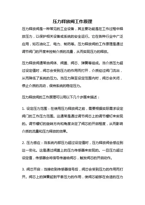
压力释放阀工作原理压力释放阀是一种常见的工业设备,其主要功能是在工作过程中释放压力,以保护相关设备或系统的安全运行。
它在各种行业中广泛应用,如石油化工、电力、制药等。
压力释放阀的工作原理是通过调节阀门的开度来控制介质的流量,从而实现压力的释放。
压力释放阀通常由阀体、阀盖、阀芯、弹簧等组成。
当介质压力超过设定值时,阀芯会受到压力的作用而打开,介质经过阀门流出,从而降低了系统的压力。
当压力降至设定范围内时,阀芯会关闭,停止介质的流动,保持系统的稳定压力。
压力释放阀的工作原理可以用以下几个步骤来描述:1. 设定压力范围:在使用压力释放阀之前,需要根据实际需求设定阀门的工作压力范围。
这通常是通过调节阀芯上的调节螺钉来实现的。
调节螺钉的旋转方向和角度决定了阀芯的开启程度,从而影响介质的流量和压力释放的效果。
2. 压力感应:当系统内部压力超过设定值时,压力释放阀会感应到这一变化。
这是通过阀盖上的压力传感器来实现的。
一旦压力超过设定值,传感器会将信号传递给阀芯,触发阀芯的开启动作。
3. 阀芯开启:当接收到传感器信号后,阀芯会受到压力的作用而打开。
阀芯上的弹簧起到平衡压力的作用,使阀芯能够在合适的压力下保持开启状态。
开启后,介质会通过阀芯的通道流出,从而降低系统的压力。
4. 压力释放:介质流经阀芯通道后,会进入阀体的出口,并被导向到排放管道中。
在这个过程中,阀芯的开启程度决定了介质的流量,从而影响了系统的压力释放效果。
通过调节螺钉的旋转方向和角度,可以进一步调整阀芯的开启程度,从而实现对压力释放的精确控制。
5. 压力恢复:一旦系统的压力降至设定范围内,传感器会停止传递信号,阀芯受到弹簧的作用而关闭。
在关闭状态下,阀芯会阻止介质继续流出,系统的压力得以恢复和稳定。
压力释放阀的工作原理简单而有效。
通过调节阀芯的开启程度,可以精确控制系统的压力,从而保护设备和系统的安全运行。
压力释放阀的应用范围广泛,在工业生产中起到了重要的作用。
YSH55-8580-130型压力释放阀使用说明书西安西变组件有限公司1.适用范围压力释放阀使用与油浸式变压器等电气设备,用于释放变压器油内部过压力的一种保护装置,当油箱内部压力升高至压力方法的开启压力值时,在2ms内迅速开启,使得油箱内压力很快降低,当降低至阀的关闭压力值时,阀门又可靠关闭,油箱内保持正常压力。
2产品型号编制办法2.1型号组成:Y(压力)S(释放)F(阀门)□(设计序列号)-□(开启压力kPa)/□(配有口径mm)KJ(带信号开关和机械信号)□(特殊环境代号)(注意:特殊环境代号:干热带地区“TA”;湿热地区“TH”;干、湿热带地区2.2型号举例:YSF1-55/130KJTH适用于湿热带地区的配有口径为130mm,开启压力为55kPa,带信号开关和机械信号装置、第一次设计的压力释放阀。
3.基本参数(见表1):表1开启压力35 55 70 85开启压力偏差±5关闭压力不小于19 29.5 37.5 45.5密封压力不小于21 33 42 514、结构和工作原理:4.1 压力释放阀的主要结构型式是外弹簧式,并可带或不带定向导流装置,它的主要部件由弹簧、阀座、弹簧座、阀壳体(罩)、标志杆、信号开关(出现盒)、密封圈等零部件组成。
4.2工作原理压力释放阀是用来保护油浸式变压器等电气设备过压力保护的安全装置,可以避免变压器油箱变形或爆裂。
当油浸式变压器内部发生事故时,油箱内的油被气化,产生大量气体,使得油箱内部压力急剧升高。
此压力如果不及时释放,将造成油箱变形或爆裂。
安装压力释放阀就是当油箱内压力升高到压力释放阀的开启压力时,压力释放阀在2ms内迅速开启,使得油箱内的压力很快降低。
当压力降到压力释放阀的关闭压力值时,压力释放阀又可靠关闭,使得油箱内永远保持正压,有效地防止外部空气、水气及其他杂质进入油箱;在压力释放阀开启同时,标志杆向上动作且明显伸出顶盖,表示压力释放阀已动作过,在压力释放阀关闭时,标志杆仍滞留在开启后的位置上,然后必须由手动才能复位。
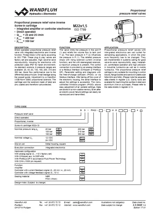
Wandfluh AG Tel. +41 33 672 72 72 E-mail: ******************Illustrations not obligatoryData sheet no.PostfachFax +41 33 672 72 12 Internet: Data subject to change 2.3-562E 1/4 CH-3714 Frutigen Edition 17 01TYPE CODEB D IPM22 --/ M E-#Pressure relief valve Direct operated Proportional, inverse Screw-in cartridge M22x1,5Nominal pressure rang p N 20 bar 20 200 bar 200 100 bar 100 315 bar 315160 bar 160 350 bar 350Nominal voltage U N 12 VDC G1224 VDCG24Slip-on coilMetal housing, square Execution connectionIntegrated electronicsHardware configurationWith analog signal (0…+10 V factory set)A1With CANopen acc. to DSP-408C1With Profibus DP in accordance Fluid Power Technology P1With CAN J1939 (on request) J1Function AmplifierController with current feedback signal (0...20 mA / 4...20 mA) R1Controller with voltage feedback signal (0...10 V) R2Sealing material NBRFKM (Vitron)D1Design-Index (Subject to change)Proportional pressure relief valve inverse Screw-in cartridge• Integrated amplifier or controller electronics • Direct operated• Q max = 20 and 25 l/min • p max = 400 bar • p N max = 350 barDESCRIPTIONDirect operated proportional pressure relief valve with integrated electronics and inverse function. Thread M22x1,5 for cavity according to ISO 7789. These plug & play valves are factory set and adjusted. High valve-to-valve reproducibility. Housing for electronics with protection class IP67 for harsh environment. As standard versions, 6 pressure ranges are available: 20, 40, 63, 100, 160, 200, 315 and 350 bar. Good flow performance due to the differential area principle. Small leakage along the poppet guide. Adjustment by a Wandfluh (VDE-Norm 0580) proportional solenoid. The cartridge and the solenoid made of steel are zinc coated and therefore rust-protected.FUNCTIONThe valve limits the pressure in the port P (1) and reliefs the volume flow to tank port T (2). The back pressure in T (2) influences the pressure in P (1). The reliefed pressure drops with rising solenoid current (inverse function), and the with deenergised solenoid, a maximum pressure is present. The control connection is provided by an analog interface or a fieldbus interface (CANopen or Profibus DP). Parameter setting and diagnosis with the free-of-charge software «PASO» or via fieldbus interface. After taking off the cover of the electronic housing, the serial interface to adjust the settings is accessible. The menu controlled Windows program «PASO» allows easy adjustment of all variable settings. Data are stored in a non-volatile memory. Even after an electric power failure settings can easily be reproduced and transmitted.APPLICATIONProportional pressure relief valves with inte-grated electronics are well suited for demanding applications, in which the pres-sure frequently has to be changed. They are implemented in systems calling for good valve-to-valve reproducibility, easy installati-on, comfortable operation and high precision in industrial hydraulics as well as in mobile hydraulics. The proportional pressure relief catridge is very suitable for mounting in control blocks, flange bodies and sandwich plates size NG4-Mini and NG6. (Please note the separate data sheets in register 2.3). Cavity tools are available for machining the cavities in steel and aluminium (hire or purchase). Please refer to the data sheets in register 2.13.M22x1,5ISO 7789Wandfluh AG Tel. +41 33 672 72 72 E-mail: ******************Illustrations not obligatory Data sheet no.Postfach Fax +41 33 672 72 12 Internet: Data subject to change 2.3-562E 2/4CH-3714 FrutigenEdition 17 01SYMBOL37s3M22x1.5T(2)X1X2X4 (nur Regler)(controller only)35.583X1X3X225,30501821, 2240706s613M DELECTRICAL SPECIFICATIONSProtection class IP 67 acc. to EN 60 529with suitable connector and closedelectronics housingSupply voltageRampsParameterisationInterfaceAnalog interface:Mating connectorPreset value signalFieldbus interface:Device receptaclesupply (male)Mating connectorDevice receptacleCANopen (male)Mating connectorDevice receptacleProfibus (female)Mating connectorPreset value signalFeedback signal interface (Sensor):(controller only)Device receptacle (female) M12, 5-polesMating connector Plug (male), M12, 5-poles(not incl. in delivery)Feedback signal:: Voltage / current state when orderingCONNECTOR WIRING DIAGRAMAnalog interface:Supply voltage +Supply voltage 0 VDCStabilised output voltagePreset value voltage +Preset value voltage -Preset value current +Preset value current -Reserved for extensionsReserved for extensionsEnable control (Digital input)Preset value voltage (PIN 4/5) resp. current (PIN 6/7) are selected withV), (PIN 4/5)Parameterisation interface (USB, Mini B) X2Under the closing screw of the housing coverFeedback signal interface (Sensor)Device receptacle (female) X4 (only controller)1 = Supply voltage (output) +2 = Feedback signal +3 = Supply voltage 0 VDC4 = not connected5 = stab. output voltage2 = Reserved for extensionsDevice receptacle Device receptacleCANopen (male) X3 Profibus (female) X3CAN PROFIBUS1 = not connected 1 = VP2 = not connected 2 = RxD / TxD - N3 = CAN Gnd 3 = DGND4 = CAN High 4 = RxD / TxD - P5 = CAN Low 5 = Shield31452123543145212354123451234123431452HYDRAULIC SPECIFICATIONSFluid Mineral oil, other fluids on requestContamination ISO 4406:1999, class 18/16/13efficiency (Required filtration grade ß 6…10≥75)see data sheet 1.0-50/2Viscosity range 12 mm2/s…320 mm2/sFluid temperature -20…+70°CPeak pressure pmax= 400 barNominal pres. ranges pN= 20 bar, 100 bar, 160 bar, 200 bar,315 bar, 350 barMin. volume flow Qmin= 0,1 l/minMax. volume flow Qmax= 25 l/min for pN=20 bar / 100 bar /160 bar / 200 barQmax= 20 l/min for pN= 315 barQmax= 5 l/min for pN= 350 barLeakage volume flow see characteristicsRepeatability ≤ 3 %Hysteresis ≤ 5 %GENERAL SPECIFICATIONSDescription Direct operated proportional pressure reliefvalve with integrated electronics inverse functionConstruction Screw-in cartridge for cavity acc. to ISO 7789Operations Proportional solenoid wet pin push type,pressure tightMounting Screw-in thread M22x1,5Ambient temperature -20…+65°C (typical)(The upper temperature limit is a guideline value for typicalapplications, in individual cases it may also be higher or lower.The electronics of the valve limit the power in case of a toohigh electronics temperature. More detailed information can beobtained from the operating instructions «DSV».)Mounting position any, preferably horizontalFastening torque MD= 50 Nm for screw-in cartridgeMD= 5 Nm for knurled nutWeight m = 1,0 kgWandfluh AG Tel. +41 33 672 72 72E-mail: ******************Illustrations not obligatoryData sheet no.PostfachFax +41 33 672 72 12 Internet: Data subject to change 2.3-562E 3/4 CH-3714 FrutigenEdition 17 01CHARACTERISTICS Oil viscosity υ = 30 mm 2/s p = f (Q) Pressure volume flow characteristics (Maximum adjustable pressure)p= f (Q) Pressure volume flow characteristics (Minimum adjustable pressure)Q L = f (p)Leakage volume flow characteristicsp red = f (l) Pressure adjustment characteristics[at Q = 10 l/min] / (s corresponds to preset value signal)p = f (l) Pressure adjustment characteristics [at Q = 5 l/min] /(s corresponds to preset value signal)NOTE!Detailed electrical characteristics and description of «DSV » electronics are shown on data sheet 1.13-76.START-UPFor DSV amplifiers as a rule no parameter settings by the customer are required. The plugs have to be connected in accordance with the chapter «Pin assignment».Controllers are supplied configured as amplifiers. The setting of the mode of control and the setting of the controller are done by the customer by software setting (USB interface, Mini B).Additional information can be found on our website:«»Free-of-charge download of the «PASO»-software and the instruction manual for the «DSV » hydraulic valves as well as the operation instruc-tion CANopen eg.Profibus DP protocol with device profile DSP-408 for «DSV ».NOTE!The mating connectors and the cable to adjust are settings is not part of the delivery. Refer to chapter «Accessories».Factory settings:Dither set for optimal hysteresis= Deadband: Solenoid switched offwith command preset value signal <5 % p Nmechanicallly pre-set at Q = 5 l/min= Limited pressure in port P (1) at 70 % of preset value signal: 95 bar with pressure range 350 bar 65 bar with pressure range 315 bar 56 bar with pressure range 200 bar 32 bar with pressure range 160 bar 25 bar with pressure range 100 bar 4 bar with pressure range 20 bar0 10 20 30 40 50 60 70 80 90 100s [%]p [bar]4003002001000 10 20 30 40 50 60 70 80 90 100s [%]p [bar]1209060300p = f (l) Pressure adjustment characteristics [at Q = 5 l/min] / (s corresponds to preset value signal)40030020010000 5 10 15 20 25Q [l/min]p [bar]N = 200 bar N = 160 bar N = 100 bar N= 20 bar504030201000 5 10 15 20 25Q [l/min]403020100 50 100 150 200 250 300 350 p [bar]Q [cm 3/min]0 10 20 30 40 50 60 70 80 90 1001251007550250I [%]p [%]Wandfluh AG Tel. +41 33 672 72 72 E-mail: ******************Illustrations not obligatoryData sheet no.PostfachFax +41 33 672 72 12 Internet: Data subject to change 2.3-562E 4/4 CH-3714 Frutigen Edition 17 01Cavity drawing according to ISO 7789–22–02–0–98For detailed cavity drawing and cavity toolssee data sheet 2.13-1003With fieldbus interface Amplifier With fieldbus interface ControllerDIMENSIONS / SECTIONAL DRAWINGS*Adjusting screw for setting the nominal pressure (-20 % / +30 %)With analog interface Amplifier and ControllerACCESSORIES • Cartridge built in:flange and sandwich bodies see register 2.3• Set-up softwaresee start-up• Cable to adjust the settings through interface USB (from plug type A to Mini B, 3 m) article no. 219.2896• Cable connector for analog interface: – straight, soldering contact article no. 219.2330 – 90°, soldering contact article no. 219.2331Recommended cable size: – Outer diameter 9…10,5 mm – Single wire max. 1 mm 2 – Recommended wire size: 0…25 m = 0,75 mm 2 (AWG18) 25…50 m = 1 mm 2 (AWG17)Technical explanation see data sheet 1.0-100PARTS LIST Position Article Description17160.2187O-ring ID 18,72 x 2,62 (NBR)18160.2170O-ring ID 17,17 x 1,78 (NBR)20154.2700Knurled nut21223.1317Dummy plug M16 x1,522160.6131O-ring ID 13,00 x1,525062.0102Cover square 30072.0021Gasket 33,2 x 59,9 x 240208.0100Socket head cap screw M4 x1050160.2188160.6188O-ring ID 18,77 x 1,78 (NBR)O-ring ID 18,77 x 1,78 (FKM)60160.2140160.6141O-ring ID 14,00 x 1,78 (NBR)O-ring ID 14,00 x 1,78 (FKM)70049.3177Back-up ring RD 14,6 x 17,5 x 1,4353790.2s 30M 22x 1.5T(2)X2X1X3X4172.4P(1).5(1)E: Venting。

减压阀使用说明一、安装与使用1.安装减压阀之前必须对管路系统进行冲洗清理,以防焊渣、氧化皮等赃物流入阀内,影响阀门正常工作。
2.减压阀应安装在便于操作和维修的地方,并且必须直立安装在水平管路上,应注意管路中介质的流向与阀体上箭头所示方向一致,切勿装反。
3.减压阀在安装使用时,应先把旁通管路上的截止阀打开,排除管路中的冷凝水和汽水混合物,以防减压阀开启时产生水击现象损坏减压阀;当无异常现象后,按顺时针方向缓慢旋转调节螺钉,将出口压力调至所需压力(以阀后表为准),调整好后将锁紧螺母背面,拧上防护罩。
4.减压阀前应安装过滤器,以防止介质中的杂质进入减压阀,影响其性能。
5.安装的减压阀前后应有一段直管,阀前直管长度约为600mm,阀后直管长度约为1000mm。
二、如出口压力高于所需压力,需要重新设定,方法如下:①关闭上游隔离阀;②把出后压力泄掉;③将导阀调节螺钉逆时针旋松,使调节弹簧处于自由状态;④慢慢开启上游隔离阀至全开;⑤顺时针慢慢向下拧紧导阀调节螺钉,出后压力逐步升高,直到设定值时将调节螺母锁定;⑥如果调压过头,须从第一步开始重新调节,即只能从低压往高压调。
电磁阀使用说明一、本阀适用于以蒸汽为加热介质,进行温度自动控制的执行机构。
可对蒸汽加热器、散热器、干燥器等蒸汽设备及各类温度自控仪、蒸汽定型机、蒸染机、蒸汽回潮机等成套设备的锅炉蒸汽管道进行二位式自动控制和远程控制。
广泛应用于染化、纺织、印染、食品、医药、卷烟、水泥制品、石油化工、冶金等部门的自控系统。
二、主要特点耐热:电磁部分、密封件部分用特种耐高温电工材料和密封材料,并应用了各种隔热措施。
耐磨:选项材合理,阀杯和导向套间巧妙地利用流体的润滑作用,减少磨损。
耐冷凝:蒸汽管道的冷凝水是影响蒸气电磁阀动作的重要因素,本阀则不受冷凝水影响。
三、结构原理本阀是由副阀和主阀两大部件构成的先导式二次开阀的电磁阀。
是靠副阀的启闭来控制主阀的通断。
根据断电时所处开关状态的不同,可分为常闭电磁阀和常开电磁阀。
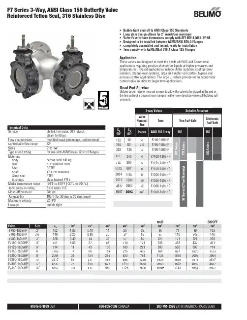
800-543-9038 866-805-7089 203-791-8396 •Bubble tight shut-off to ANSI Class 150 Standards • Long stem design allows for 2” insulation minimum• Valve Face-to-face dimensions comply with API 609 & MSS-SP-68•Designed to be installed between ASME/ANSI B16.5 Flanges • Completely assembled and tested, ready for installation •Tees comply with ASME/ANSI B16.1 Class 125 FlangesApplicationThese valves are designed to meet the needs of HVAC and Commercial applications requiring positive shut-off for liquids at higher pressures and temperatures. Typical applications include chiller isolation, cooling tower isolation, change-over systems, large air handler coil control, bypass and process control applications. The large C v values provide for an economical control valve solution for larger fl ow applications.Dead End ServiceUtilizes larger retainer ring set screws to allow the valve to be placed at the end of the line without a down stream fl ange in either fl ow direction while still holding full pressure.MOD ON/OFF ValveSize C v 10°20°30°40°50°60°70°80°90°F750-150SHP 2”102 1.50 6.10142639567799102F765-150SHP 2½”146 2.208.8020375580110142146F780-150SHP 3”228 3.4014325787125171221228F7100-150SHP 4”451 6.802763114171248338437451F7125-150SHP 5”7141143100180271393536693714F7150-150SHP 6”1103176615427841960782710701103F7200-150SHP 8”2064311242895207841135154820022064F7250-150SHP 10”35175321149288613361934263834113517F7300-150SHP 12”483773290677121918382660362846924837F7350-150SHP 14”6857103411960172826063592514366516857F7 Series 3-Way, ANSI Class 150 Butterfl y Valve Reinforced Tefl on Seat, 316 Stainless DiscTechnical Data Servicechilled, hot water, 60% glycol,steam to 50 psi Flow characteristic modifi ed equal percentage, unidirectional Controllable fl ow range 82°Sizes2" to 14"Type of end fi tting for use with ASME/class 125/150 fl anges Materials Body Disc Seat ShaftGland seal Bushingscarbon steel full lug 316 stainless steel RPTFE17-4 PH stainless PTFEglass backed PTFEMedia temperature range -20°F to 400°F [-30°C to 204°C]Body pressure rating ANSI Class 150 Close-off pressure 285 psiRangeability100:1 (for 30 deg to 70 deg range)Maximum velocity 32 FPS Leakagebubble tight3-way Valves Suitable Actuators Valve Nominal SizeTypeNon Fail-SafeElectronic Fail-Safe C v 90°C v 60°Inches ANSI 150 3-way 1501502F750-150SHPG M S e r i e sP R S e r i e sG K S e r i e s 2½F765-150SHP 3F780-150SHP 4F7100-150SHP 5F7125-150SHP S Y S e r i e s (2 Y e a r W a r r a n t y )6F7150-150SHP 8F7200-150SHP 10F7250-150SHP 12F7300-150SHP 14*F7350-150SHP1021462284517141103206435174837685780125248393607113519342660359256866-805-7089 203-791-8396 LATIN AMERICA / CARIBBEANMaximum Dimensions (Inches)F750-150SHP 2”102 4.50 6.38 6.3816.50 4.7545/8-11 UNC GK150Electronic Fail-SafeF765-150SHP 2½”146 5.00 6.88 6.8817.00 5.5045/8-11 UNC150F780-150SHP 3”228 5.507.567.5617.50 6.0045/8-11 UNC 150F750-150SHP 2”102 4.50 6.38 6.3816.50 4.7545/8-11 UNC 2*GK285F765-150SHP 2½”146 5.00 6.88 6.8817.00 5.5045/8-11 UNC 285F780-150SHP 3”228 5.507.567.5617.50 6.0045/8-11 UNC 285F750-150SHP 2”102 4.50 6.38 6.3816.50 4.7545/8-11 UNC GM150Non-Spring Return Electronic Fail-Safe (K)F765-150SHP 2½”146 5.00 6.88 6.8817.00 5.5045/8-11 UNC 150F780-150SHP 3”228 5.507.567.5617.50 6.0045/8-11 UNC 150F7100-150SHP 4”451 6.508.638.6318.007.5085/8-11 UNC 150F750-150SHP 2”102 4.50 6.38 6.3816.50 4.7545/8-11 UNC 2*GM285F765-150SHP 2½”146 5.00 6.88 6.8817.00 5.5045/8-11 UNC 285F780-150SHP 3”228 5.507.567.5617.50 6.0045/8-11 UNC 285F750-150SHP 2”102 4.50 6.38 6.3814.00 4.7545/8-11 UNC PR/PK285F765-150SHP 2½”146 5.00 6.88 6.8814.50 5.5045/8-11 UNC 285F780-150SHP 3”228 5.507.567.5615.00 6.0045/8-11 UNC 285F7100-150SHP 4”451 6.508.638.6316.007.5085/8-11 UNC 285F7125-150SHP 5”7147.509.759.7524.258.5083/4-10 UNC SY4…285F7150-150SHP 6”11038.0010.2510.2524.759.5083/4-10 UNC 285F7200-150SHP 8”20649.0011.5011.5032.0011.7583/4-10 UNC SY4…150F7250-150SHP 10”351711.0013.8113.8133.0014.25127/8-9 UNC SY4…150SY5…285F7300-150SHP 12”483712.0015.8115.8135.0017.00127/8-9 UNC SY5…150SY7…285F7350-150SHP14”685714.0017.6217.6236.0018.75121-8 UNCSY7…285F7 Series 3-Way, ANSI Class 150 Butterfl y ValveReinforced Tefl on Seat, 316 Stainless DiscDimensions “A, B and C” do not include fl ange gaskets. (3 required per valve)Application Notes1. Valves are rated at 285 psi differential pressure in the closed position @ 100°F media temperature.2.Valves are furnished with lugs tapped for use between ANSI Class 125/150 fl anges conforming to ANSI B16.5 Standards.3.3-way assemblies are furnished assembled with Tee, calibrated and tested,ready for installation. All 3-way assemblies require the customer to specify the 3-way confi guration code prior to order entry to guarantee correct place-ment of valves and actuator(s) on the assembly.4. Dimension “D” allows for actuator(s) removal without the need to remove the valve from the pipe.5. Weather shields are available, dimensional data furnished upon request.6. Dual actuated valves have single actuators mounted on each valve shaft.7.Flange gaskets (3 required, not provided with valve) MUST be used between valve and ANSI fl ange.8. F lange bolts are not included with the valve. These are furnished by others.SHP seriesvalves have a preferred flow direction.P r e f e r r e d F l o w r a t e0DCABB,CDAPRBUP-3-TApplicationOn/Off, Floating Point, Non Fail-Safe, 24...240 V, NEMA 4XTechnical dataElectrical dataNominal voltageAC 24...240 V / DC 24...125 V Nominal voltage frequency 50/60 Hz Power consumption in operation 20 W Power consumption in rest position 6 WTransformer sizing 20 VA @ AC/DC 24 V (class 2 power source), 23 VA @ AC/DC 120 V, 52 VA @ AC 230 V Auxiliary switch2 x SPDT,3 A resistive (0.5 A inductive) @ AC 250 V, 1 x 10° / 1 x 0...90° (default setting 85°)Switching capacity auxiliary switch 3 A resistive (0.5 A inductive) @ AC 250 V Electrical Connection Terminal blocks, (PE) Ground-Screw Overload Protectionelectronic thoughout 0...90° rotation Functional dataDirection of motion motor reversible with app Manual override 7 mm hex crank, supplied Angle of rotation 90°Running Time (Motor)35 s Noise level, motor 68 dB(A)Position indicationintegral pointer Safety dataDegree of protection IEC/EN IP66/67Degree of protection NEMA/UL NEMA 4XEnclosure UL Enclosure Type 4XAgency ListingcULus acc. to UL60730-1A/-2-14, CAN/CSA E60730-1:02, CE acc. to 2014/30/EU and 2014/35/EU Quality Standard ISO 9001Ambient temperature -22...122°F [-30...50°C]Ambient humidity Max. 100% RH Servicingmaintenance-free Weight Weight13 lb [5.9 kg]MaterialsHousing materialdie cast aluminium polycarbonate coverProduct featuresPR Series valve actuators are designed with an integrated linkage and visual position indicators. For outdoor applications, the installed valve must be mounted with the actuator at or above horizontal. For indoor applications the actuator can be in any location including directly under the valve.PRBUP-3-T Operation The PR series actuator provides 90° of rotation and a visual indicator shows the position of thevalve. The PR Series actuator uses a low power consumption brushless DC motor and iselectronically protected against overload. A universal power supply is furnished to connectsupply voltage in the range of AC 24...240 V and DC 24...125 V. Included is a smart heater withthermostat to eliminate condensation. Two auxiliary switches are provided; one set at 10° openand the other is field adjustable. Running time is field adjustable from 30...120 seconds by usingthe Near Field Communication (NFC) app and a smart phone.†Use 60°C/75°C copper wire size range 12...28 AWG, stranded or solid. Use flexible metalconduit. Push the listed conduit fitting device over the actuator’s cable to butt against theenclosure. Screw in conduit connector. Jacket the actuators input wiring with listed flexibleconduit. Properly terminate the conduit in a suitable junction box. Rated impulse Voltage 4000V. Type of action 1. Control pollution degree 3.AccessoriesMechanical accessories Description TypeHand crank for PR, PKR, PM ZG-HND PR Electrical installationMeets cULus requirements without the need of an electrical ground connection.Universal Power Supply (UP) models can be supplied with 24 VAC up to 240 VAC, or 24 VDC upto 125 VDC.Disconnect power.Provide overload protection and disconnect as required.Two built-in auxiliary switches (2x SPDT), for end position indication, interlock control, fanstartup, etc.Actuators may be controlled in parallel. Current draw and input impedance must be observed.Warning! Live electrical components!During installation, testing, servicing and troubleshooting of this product, it may be necessaryto work with live electrical components. Have a qualified licensed electrician or other individualwho has been properly trained in handling live electrical components perform these tasks.Failure to follow all electrical safety precautions when exposed to live electrical componentscould result in death or serious injury.Wiring diagramsOn/OffPRBUP-3-T On/OffFloating Point Auxiliary SwitchesDimensionsDimensional drawings。
采技服公司定压放气阀产品说明一、定压放气阀生产调试1、调试定压放气阀之前先将其完全关闭,确认套管压力表工作正常后,将定压放气阀出口端球阀和其进口端套管翼阀打开。
2、缓慢旋转压力调节手柄,开启(逆时针旋转压力调节手柄)定压放气阀,压力调节手柄旋转一圈后,定压放气阀的起跳压力为4Mpa,随后每开启一圈起跳压力下降0.4-0.6Mpa。
3、旋转压力调节手柄,将其起跳压力调至该井设定套压值处,稳定20分钟。
如套压高于该井设定套压,继续开启放气阀。
4、如套压高于该井设定套压,开启放气阀半圈,否则关放气阀半圈,稳定20分钟。
5、如套压仍高于该井设定套压,重复第4步,当套压稳定在设定套压后,该井定压放气阀调节完毕。
注意:因流程回压不同,或者各井套管气量大小不一,在设定套压相同情况下,各井压力调节杆开启圈数亦不同。
6、对于套压较高的井(套压>5Mpa),调试时要分步调节。
每次调节使套压下降0.5Mpa,稳定20分钟,待流程稳定后,继续进行。
避免影响流程,尽量减少因套管放气产生压力波动,导致流程高压报警等事件发生。
7、所有井在调试后,由于放气流程的不稳定,可能会引起调节后的套压与设计套压有偏差,需要对定压放气阀进行进一步调节(执行第四步)。
二、定压放气阀的维护1、定压放气阀在工作的过程中,密封件长期在套管气的冲击、腐蚀下可能会被损坏,导致其密封性能逐渐下降。
破坏比较严重时会失去其密封性能,使定压放气阀漏气。
发现漏气,及时关闭定压放气阀两端的阀门,泄压后打开压帽,取出密封件进行更换。
更换后,按照“定压放气阀生产调试”操作规程重新调试。
2、在平时检查的过程中,如果发现定压放气阀调节能力失去作用,不能按要求控制套管压力,需要更换定压放气阀的压力调节弹簧。
关闭定压放气阀两端的阀门,泄压后,打开压帽,取出弹簧进行更换。
更换后,按照“定压放气阀生产调试”操作规程重新调试。
3、收拾整理工具,清理作业区卫生。
三、定压放气阀拆卸操作规程1、关闭套管翼阀和定压放气阀针型阀及其旁通,从放气口泄压(需要事先同时平台安全监督,杜绝此时进行进口区动火作业),直至套压表指针归零,确保压力全部泄掉;2、拆卸压帽、调节杆;3、取出锥形杆及弹簧,清理里面的原油或污物;4、对调节杆、弹簧及阀杆除锈,更换损坏的盘根、弹簧及阀杆,抹上黄油,清理丝扣,各部件归复原位;5、恢复原流程,开套管翼阀,检查定压放气阀有无泄露;6、开旁通阀门,根据平台要求,按照“定压放气阀生产调试”操作规程重新调试调试套压;7、收拾整理工具,清理作业区卫生。
压力释放阀PRESSURE RELEASE VALVE使用说明书OPERATION INSTRUCTION明远电器设备SHENYANG MINGYUAN ELECTRIC EQUIPMENT CO., Ltd.本说明书适用于我公司生产的系列变压器用压力释放阀,阐述其用途、性能、规格、技术参数、使用及安装,供用户参考。
The Operation Instruction is applicable to pressure release valve of a series of transformers manufactured by our company, indicating its application, performances, specifications, technical parameters, usage and installation for uses’ reference.1. 压力释放阀用途和性能压力释放阀适用于油浸式电力变压器、电力电容器及有载分接开关等,用来保护油箱。
当油浸式变压器在运行中出现故障时,由于线圈过热,使一部分变压器油汽化,变压器油箱中压力迅速增加,这时压力释放阀在2ms迅速动作,释放压力,保护油箱不致变形或爆裂。
油箱的压力再升高而达到开启压力时,压力释放阀应再次动作,直到油箱的压力降到正常值。
由于压力释放阀动作后能可靠关闭,油箱外的水和空气不能进入油箱,变压器部不会受大气污染。
1.Application and performancePressure release valves play a vital role in the protection of oil-immersed electrical equipments, such as transformers, high voltage switch gears, capacitor and on load tap-changers, etc. This device can prevent the oil-immersed electrical equipment from deformation or rupture. Should a fault occur in such electrical equipment, from deformation of rupture? Should a fault occurring in such electrical equipment, they are instantaneously vaporize the oil causing extremely rapid build-up of gaseous pressure? If mounting this type pressure release device on the oil-tank, when the pressure reaches to its opening pressure, it opens automatically within 2ms and relieves the pressure.2.型号、规格及基本参数Type, specification and technical parameters2.1 型号的含义 Meaning of typeY S F□—□ / □□□特殊环境代号(Special environment)带机械信号标“J”(“J”:mechanical signal)带信号开关标“K”(“K”:electrical signal)两者都带标“KJ”(“KJ”:Both with signal)喷油有效口径(Caliber of oil-gushing tube)mm开启压力(Opening pressure)kPa设计序号(Design serial number)阀(valve)释放(release)压力(pressure)注:特殊环境代号 note: special environment:TA: 干热带地区 dry tropicTH: 湿热带地区 humid tropicT: 干、湿热带地区 dry、humid tropic例:YSF16-55/130KKJT开启压力为55kPa,喷油口径为φ130mm,带电信号、机械信号。
ContentsGENERAL DESCRIPTION 3 TYPICAL SECTION 3 FUNCTIONAL SYMBOLS 4 MODEL CODES 5 OPERATING DATA 6 PERFORMANCE DATAPressure override, Off-Load . . . . . . . . . . . . . . . . . . . . . . . . . . . . . . . . . . . . . . . . . . . . . . . . . . . . . . . . . . . . . . . . . . . .8 Pressure override when relieving . . . . . . . . . . . . . . . . . . . . . . . . . . . . . . . . . . . . . . . . . . . . . . . . . . . . . . . . . . . . . . .9 Pressure gain . . . . . . . . . . . . . . . . . . . . . . . . . . . . . . . . . . . . . . . . . . . . . . . . . . . . . . . . . . . . . . . . . . . . . . . . . . . . . . .9 Step response . . . . . . . . . . . . . . . . . . . . . . . . . . . . . . . . . . . . . . . . . . . . . . . . . . . . . . . . . . . . . . . . . . . . . . . . . . . . .9INSTALLATION DIMENSIONSKBCG-6/8 Models . . . . . . . . . . . . . . . . . . . . . . . . . . . . . . . . . . . . . . . . . . . . . . . . . . . . . . . . . . . . . . . . . . . . . . . . . .10 Mounting surfaces . . . . . . . . . . . . . . . . . . . . . . . . . . . . . . . . . . . . . . . . . . . . . . . . . . . . . . . . . . . . . . . . . . . . . . . . . .11 CGVM-6-10-R Subplate . . . . . . . . . . . . . . . . . . . . . . . . . . . . . . . . . . . . . . . . . . . . . . . . . . . . . . . . . . . . . . . . . . . . . .11ELECTRICAL INFORMATIONBlock diagram . . . . . . . . . . . . . . . . . . . . . . . . . . . . . . . . . . . . . . . . . . . . . . . . . . . . . . . . . . . . . . . . . . . . . . . . . . . . .12 Wiring connections . . . . . . . . . . . . . . . . . . . . . . . . . . . . . . . . . . . . . . . . . . . . . . . . . . . . . . . . . . . . . . . . . . . . . . . . .13FURTHER INFORMATION 152EATON Proportional pressure relief valves V-VLPO-MC003-E1 September 20203EATON Proportional pressure relief valves V-VLPO-MC003-E1 September 2020These two-stage pressure relief valves offer extensive application possibilities through their ability to control the pressure setting in proportion to an applied electrical input (up to a pressure limit which is manually adjustable and lockable) .The integral amplifier allows the pressure to be controlled from a low power command signal: either a voltage or current command . The amplifier is mounted in a robust metal housing and electrical connections are via an industry standard 7-pin plug . Factory-set adjustments ensure high reproducibility valve-to-valve .Basic characteristicsMax . pressure . . . . . . . . . . . . . . . . . . . . . . . . . . . . . . . .350 bar (5000 psi) Max . flow rate . . . . . . . . . . . . . . . . . . . . . . . . . . . . . . . .400 L/min (106 USgpm)Mounting face to ISO 6264:For KBCG-6 . . . . . . . . . . . . . . . . . . . . . . . . . . . . . . . . . . . . . AR-06-2-A For KBCG-8 . . . . . . . . . . . . . . . . . . . . . . . . . . . . . . . . . . . . . AS-08-2-AFeatures and benefits • Remote electrical proportional control of pressure from a choice of five pressure ranges per valve size .• Excellent repeatability and stable performance results from cartridge design of mainstage elements .• Low installed cost and space requirement from high power/size ratios (more than double that of many conventional designs) .• On-board ramp adjustment .General descriptionT ypical sectionManual and electricalpilots internallydrained to port T.Model code 7= Blank7-pin plugManual pilot internallydrained to port T;electrical pilot drainedto side drain port u.Model code 7= 37-pin plugu Tapped port on side of pilot head . Manual and electrical pilots drained to side drain port u.Model code 7= 17-pin plug¨¨¨Functional symbolsu Tapped port on side of pilot head .4EATON Proportional pressure relief valves V-VLPO-MC003-E1 September 20205EATON Proportional pressure relief valves V-VLPO-MC003-E1 September 20201KB 8Z 2*9*3G 1034*11A 5*12P*76***13*7*14111Valve typeKB Proportional valve with integral amplifier, B series 2TypeC Pressure relief 3MountingG Subplate mounted 4Interface - ISO 6264With B port high pressure inlet, A port reduced pressure outlet 6 AR-06-2-A 8 AS-08-2-A 5Manual adjustment W Screw/locknut 6Controlled pressure rangeBased on inlet pressure of 350 bar (5000 psi) . Note, with 100 bar (1450 psi) inlet the lower limits will be 2-3 bar (30-43 psi) lower40 100 160 250 3506-40 bar (87-580 psi) 7,75-100 bar (112-1450 psi) 8,5-160 bar (125-2300 psi) 8,5-250 bar (125-3625 psi) 9-350 bar (139-5000 psi)7DrainBlankManual and electrical pilots drain internally to T port 1Manual and electrical pilots drained to side port drain 3Manual pilot internally drained to T port, electrical pilot drained to side port drain 8Manual overridesZ No overrides 9Electrical command options M1+/- 10 volts control signal M24-20 mA control signal 10Ramps3Standard ramp for KBCG- 6/8 valve types 11Command/pressure characteristicA Standard 12Electrical connection PC77 pin connector, without plug supplied PE77 pin connector, with plug supplied PH7As PE7 but with pin ‘C’ used for enable signal PR7as PC7 but with pin ‘C’ used for enable signal 13Coil rating H124V DC amplifier supply 14Design number, 1* series 11Subject to change . Installation dimensions unaltered for design numbers 10 to 19 respectivelyModel codesT o conform to the EC Electromagnetic Compatibility directive (EMC) this KBCG valve must be fitted with a metal 7-pin plug. The screen of the cable must be securely connected to the shell of the metal connector. A suitable IP67 rated connector is available from Eaton, part no. 934939. Alternatively a non IP67 rated connector is available from ITT -Cannon, part no. CA 02 COM-E 14S A7 P .6EATON Proportional pressure relief valves V-VLPO-MC003-E1 September 2020Operating dataStandard test conditions are with antiwear hydraulic oil at 36 cSt (168 SUS) and 50°C (122°F)Maximum pressures:Ports P and X ▲350 bar (5000 psi)Port T ▲ in KBCG-*-****-Z valves2 bar (30 psi)Port T ▲ in KBCG-*-****-1/3-Z valves350 bar (5000 psi)Side drain port ▲2 bar (30 psi)▲ Back pressure at these ports additive to the pressuresetting of the valve.Rated flow at Δp = 6 bar (87 psi):KBCG-6200 L/min (52.8 USgpm)KBCG-8400 L/min (105.7 USgpm)Vent u flow with valve at rated flow1 L/min (0.26 USgpm)u See “Venting”, page 8.Pilot control drain flow, when valve is limiting systempressure, i.e. flow P to T occurring:KBCG-61,3 L/min (0.34 USgpm)KBCG-82,0 L/min (0.53 USgpm)Coil or amplifier rating24V x 40W max. (22 to 36V including 10% pk.-to-pk.max. ripple)Command signal:Volts (see model code 9 - 1)0 to +10V or 0 to -10VInput impedance 47 kΩCommon mode voltage to pin B 4VCurrent (see model code 9 - 2) 4 to 20 mAInput impedance 100ΩValve enable signal:Enable >9.0V (36V max)Disable <2.0VInput impedance 36 kΩ7-pin plug connector Pin DescriptionA Power supply positive (+)B Power supply 0V and current command returnC Valve enable (PH7 & PR7)D Command signal (+V or current in)E Command signal (-V or current GND)F Output monitorView of pins of fixed half G Protective groundElectromagnetic compatibility (EMC)IEC 61326-2-1 (Electrical equipment for measurement, control and laboratory use)Conducted Emissions CISPR11 -2015-06 Ed 6.0/EN55011 - Class A, 150kHz to 30MHzRadiated Emissions CISPR11 -2015-06 Ed 6.0 /EN55011 - Class A, 30MHz – 1GHzRF Continuous Conducted disturbances IEC 61000-4-6, 3Vrms Class A 150 KHz to 80 MHzRF Electromagnetic Field, 80MHz to 1GHZ, 10V/m; 1.4GHz to 2.7GHz, 3V/m; Meets Criterion ASurge: IEC 61000-4-5• DC Power Port : ±1kV• Signal/Control Port : ±1kVElectrical Fast Transients IEC 61000-4-4, Class B• DC Power Port : ±1kV• Signal/Control Port : ±0.5kVElectrostatic discharges (ESD) IEC 61000-4-2, Class B• Air ±8kV• Contact ±4kVROHS Compliance:Complies with: Restriction of Hazardous Substances (RoHS) Directive 2011/65/EUMonitor signal (pin F) 1.7 V/amp solenoid currentOutput impedance10 kΩOperating dataPressure gain See graphFactory setting - Maximum with 100% command signal.Pressure override when relieving and when off-load See graphsLinearity, between 10% and 100% of rated pressure:KBCG-6 models at 100 L/min (26 USgpm)<6%KBCG-8 models at 200 L/min (52 USgpm)<6%Hysteresis<6% (with factory-set dither)Repeatability<1.3% of rated pressureReproducibility, valve-to-valve (at factory settings):Pressure at 100% command signal≤5%Protection:Electrical Reverse polarity protectedEnvironmental IEC 529, Class IP67Mass (weight):KBCG-65,36 kg (11.8 lb)KBCG-86,26 kg (13.8 lb)Supporting products:Auxiliary electronic modules (DIN-rail mounting):EHA-CON-201-A-2* Signal converter See catalog 2410BEHD-DSG-201-A-1* Command signal generator See catalog 2470EHA-RMP-201-A-2* Ramp generator See catalog 2410BEHA-PID-201-A-2* PID controller See catalog 2427EHA-PSU-201-A-10 Power supply See catalog 2410BSubplates, size 03See catalog 2425Mounting bolts n See catalog 2314An Note: If not using Vickers™ recommended bolt kits, boltsmust be to ISO 898 grade 12.9 or stronger.Mounting attitude No restriction, provided that the valve is kept full of fluid through port T.7EATON Proportional pressure relief valves V-VLPO-MC003-E1 September 20208EATON Proportional pressure relief valves V-VLPO-MC003-E1 September 2020Pressure override, off-load Graphs show the minimum pressures obtainable:a) With 0 mA current to the solenoid coil b) When the valve is vented (see following explanation) .Venting When the vent port X (or alternative vent port in the valve body) is connected to the reservoir via a suitable 2-way pilot valve, the mainstage of the relief valve opens to allow full flow from P to T at low pressure drop . The minimum pressure drop is obtained when the pilot valve is also de-energized . The total pressure drop through the venting 2-way valve and pipework is additive to the pressure at P . While the valve is vented the system pressure cannot be controlled via the proportional solenoid . This control feature is frequently used during off-load periods in machine cycle times . If lower off-load system pressures are required then additional full flow unloading valves are recommended, e .g . Vickers™ CV series cartridge valves . Note: All valves are with pilot valve de-energized .Data is typical with oil at 36 cSt (168 SUS) and at 50°C (122°F)024810bar 60255075100125psiKBCG-815097531V al vepre ssur ed rop400 L/min400608010020030020Flow rate 100USgpm 024810bar 60255075100125150psi13579KBCG-6V al vepre ssur ed ro pKBCG-6*-160/250/350KBCG-6*-100KBCG-6*-40 (also KBCG-6*-350 vented)KBCG-6*-40 vented 0501001502001020304050USgpm Flow rate L/min Performance data9EATON Proportional pressure relief valves V-VLPO-MC003-E1 September 2020Performance data050100150200250300350bar 010002000300040005000psiKBCG-8KBCG-6020406080100200400L/min USgpm Flow rate40801200203040L/minUSgpm16030010020050P r e s s u r e1002030405060708090100%50100150200250300bar 01000200030004000psi % max. solenoid current P r e s s u r e 10Pressure override when relievingPressure gain Typical pressure versus command signal response of KBCG-6-250 model .Step response KBCG models with factory-set gain .Test method 1 . T rapped volume between pump and test valve, as in table .2 . Flow rate set at pump, as in table .3 . Response = time from step input signal until pressure reaches 90% of step change, as measured by transducer .ModelCurve number 123456789KBCG-**-40•KBCG-**-100••KBCG-**-160•••KBCG-**-250••••••KBCG-**-350••••••Valve sizeTest conditions:Trapped volume Flow rate Step size:Pressure demand Response Time (ms)62,0 liters (0.53 USg)100 L/min (26 USgpm)0 to 100%100% to 025 to 100%100 to 25%10070405084,0 liters (1.06 USg)200 L/min (52 USgpm)0 to 100%100% to 025 to 100%100 to 25%11070506510EATON Proportional pressure relief valves V-VLPO-MC003-E1 September 2020KBCG-6/8 modelsDimensions are shown in mm (inches)To bleed air,end of coretoafter bleedingis complete.connectorremoval directive (EMC) this KBCG valve must be fitted with a metal 7-pin plug. The screen of the cable must be securely connected to the shell of the metal con-nector. A suitable IP67 rated connector is available from Eaton, part no. 934939. Alternatively a non IP67 rated connector is available from ITT -Cannon, part no. CA 02 COM-E 14S A7 P .Model A B C D E RAD ØF (DIA)KBCG-658,035,068,035,012,020,0(2 .3)(1 .4)(2 .7)(1 .4)(0 .5)(0 .78)KBCG-842,039,083,030,016,026,0(1 .7)(1 .54)(3 .3)(1 .2)(0 .63)(1 .02)Model G H ØJ (DIA)K L KBCG-679,082,013,5176,020,0(3 .1)(3 .23)(0 .53)(7 .0)(0 .78)KBCG-8103,0106,017,0183,025,0(4 .1)(4 .2)(0 .7)(7 .2)(1 .0)Installation dimensions11EATON Proportional pressure relief valves V-VLPO-MC003-E1 September 2020Mounting surfaces,ISO 6264AR-06-2-A AS-08-2-AWhen a subplate is not used, a raised pad must be provided for mounting . The pad must be flat within 0,001 mm/100 mm (0 .0001”/10”) and smooth within 0,8 μm (32 μin) . Dimensional tolerances are ±0,2 mm (±0 .008”) except where indicated .Port functions:P = Pressure inlet T = Outlet to reservoirX = Vent, or remote control portCGVM-6-10-R Subplate▲ Tolerance on bolt and pin locations ±0,1 mm (±0 .004”) .u T hese ISO standard dimensions can be used, but improved flow paths to and from valve are obtained by using 48,0 (1 .89) instead of 47,5 (1 .87), and 22,6 (0 .89) instead of 22,1 (0 .87) .● I SO standard does not give UNC bolt sizes . These are recommended equivalents to metric sizes specified in the standard .(0.24) deep min.remote port is not to be usedG 1/4 (1/4" BSPF) x 12,0 (0.47)Installation dimensionsSize A B C D EFH JK LAR-0680 (3 .2)13,1 (0 .5)53,8 (2 .12)13,1 (0 .5)47,5u (1 .87)22,1(0 .87)22,1u (0 .87)13,1 (0 .5)53,8 (2 .12)AS-08118 (4 .7)35,0 (1 .4)66,7 (2 .63)16,3 (0 .7)55,6 (2 .19)33,4 (1 .35)11,1 (0 .44)23,8 (0 .94)16,0 (0 .63)70,0 (2 .76)Size M N ØP (DIA)Q ØT (DIA)ØX (DIA)Y Thread x Min. Full thread DepthAR-0613,1 (0 .5)26,9 (1 .06)14,7 (0 .58)80 (3 .2)14,7 (0 .58)4,8 (0.19)M12 x 21 (7/16” UNF x 0.83) ●AS-0816,0 (0 .63)35,0 (1 .38)23,4 (0 .92)102 (4 .0)23,4 (0 .92)6,3 (0.25)M16 x 30 (5/8” UNF x 1.2) ●12EATON Proportional pressure relief valves V-VLPO-MC003-E1 September 20207-pin plug connectionsA +24V BPower 0VC EnableD Non-inverting EInvertingCommand signalFCurrent monitor GProtective ground Block diagramWiringConnections must be made via the 7-pin plug mounted on the amplifier . Recommended cable sizes are:Power cablesFor 24V supply:0,75 mm 2 (18 AWG) up to 20m (65 ft)1,00 mm 2 (16 AWG) up to 40m (130 ft)Signal cables0,50 mm 2 (20 AWG)Screen (Shield)A suitable cable should have at least 6 cores with pairs of conductors individually screened and an overall screen . Cable outside diameter 8,0-10,5 mm (0 .31- 0 .41 inches) . See connection diagrams on next page .▲ In valves with PH7 or PR7 type electrical connection .Electrical informationAll power must be switched off before connecting or disconnecting any plugs.13EATON Proportional pressure relief valves V-VLPO-MC003-E1 September 2020Wiring connections for M1 valves with enable featureotee:N In applications where the valve must conform toEuropean RFI/EMC regulations, the outer screen (shield) must be connected to the outer shell of the 7 pin connector, and the valve body must befastened to the earth ground . Proper earth grounding practices must be observed in this case, as any differences in command source and valve ground potentials will result in a screen (shield) ground loop .User PanelshellKB.. PR7/PH7 valveconnected to groundVoltage input (M1) wiringSpool position monitor voltage (pin F) will be referenced to the KB valve local ground .Electrical information14EATON Proportional pressure relief valves V-VLPO-MC003-E1 September 2020Wiring connections for M2 valves with enable featureotee:N In applications where the valve must conform toEuropean RFI/EMC regulations, the outer screen (shield) must be connected to the outer shell of the 7 pin connector, and the valve body must befastened to the earth ground . Proper earth grounding practices must be observed in this case, as any differences in command source and valve ground potentials will result in a screen (shield) ground loop .Electromagnetic Compatibility (EMC) It is necessary to ensure that the valve is wired up as above. For effective protection the user electrical cabinet, the valve subplate or manifold and the cable screens should be connected to efficient ground points. The metal 7 pin connector part no. 934939 should be used for the integral amplifier. In all cases both valve and cable should be kept as far away as possible from any sources of electromagnetic radiation such as cables carrying heavy current, relays and certain kinds of portable radio transmitters, etc. Difficult environ-ments could mean that extra screening may be necessary to avoid the interfer-ence. It is important to connect the 0V lines as shown above. The multi-core cable should have at least two screens to separate the demand signal and monitor output from the power lines. The enable line to pin C should be outside the screen which contains the demand signal cables.User Panel shellKB.. PR7/PH7connected to groundCurrent input (M2) wiringSpool position monitor voltage (pin F) will be referenced to the KB valvelocal ground .Electrical informationFurther informationHydraulic fluidsMaterials and seals used in these valves are compatible with:Anti-wear petroleum oils . . .L-HM Non-alkyl basedphosphate esters . . . . . . . . . . . . .L-HFD The extreme operating range is 500 to 13 cSt (270 to 70 SUS) but the recommended running range is 54 to 13 cSt (245 to 70 SUS) . For further technical information about fluids see 694 .Contamination control requirements Recommendations on contamination control methods and the selection of products to control fluid condition are included in publication 9132or 561, “Guide to Systemic Contamination Control” . The book also includes information on the concept of “ProActive Maintenance” . The following recommendations are based on ISO cleanliness levels at 2 μm, 5 μm and 15 μm .For products in this catalog the recommended levels are:Up to 210 bar(3000 psi) . . . . . . . . . . . . . . . . . . . . .18/16/13 Above 210 bar(3000 psi) . . . . . . . . . . . . . . . . . . . . .17/15/12Installation and start-upguidelinesThe proportional valves inthis catalog can be mountedin any attitude but it may benecessary, in certain demandingapplications, to ensure thatthe solenoids are kept full ofhydraulic fluid .If this proves to be the caseany accumulated air can bebled from the solenoid bleedscrew . This task is easier if thevalve has been mounted basedownwards . Good installationpractice dictates that the tankport, and any drain port, arepiped so as to keep the valve fullof fluid once the system start-uphas been completed .TemperaturesFor petroleum oil:Min . . . . . . . . . . . . . . . . . . . . . . . . .-20°C (-45°F)Max . . . . . . . . . . . . . . . . . . . . .+70°C (158°F)For fluids where limits areoutside those of petroleum oil,consult fluid manufacturer orEaton representative . Whateverthe actual temperature range,ensure that viscosities staywithin those specified under“Hydraulic Fluids” .Ambient for:Valves at full performancespecification: -20 to +70°C(-4 to +158°F) .Valves, as above, will operateat temperatures of 0 to -20°C(32 to -4°F) but with a reduceddynamic response .Storage:-25 to +85°C (-13 to +185°F)Seal kitsPilot valve:KBCG-3 . . . . . . . . . . . . . . . . . . . . .02-145869Mainstage valves:KBCG-6 . . . . . . . . . . . . . . . . . . . . . . . . . .614824KBCG-8 . . . . . . . . . . . . . . . . . . . . . . . . . .61493115 EATON Proportional pressure relief valves V-VLPO-MC003-E1 September 2020Eaton1000 Eaton Boulevard Cleveland, OH 44122 United States © 2020 EatonAll Rights ReservedPrinted in USADocument No. V-VLPO-MC003-E1 September 2020Eaton is a registered trademark.All trademarks are propertyof their respective owners.EatonHydraulics Operations Asia Pacific11th Floor Hong Kong New World Tower300 Huaihai Zhong RoadShanghai 200021ChinaTel: 86-21-6387-9988Fax: 86-21-6335-3912EatonHydraulics Operations EuropeRoute de la Longeraie 71110 MorgesSwitzerlandTel: +41 (0) 21 811 4600Fax: +41 (0) 21 811 4601EatonHydraulics Operations USA14615 Lone Oak RoadEden Prairie, MN 55344USATel: 952-937-9800Fax: 952-294-7722www .hydraulics .eaton .comChanges to the products, to the information contained in thisdocument, and to prices are reserved; so are errors and omissions.Only order confirmations and technical documentation by Eaton isbinding. Photos and pictures also do not warrant a specific layout orfunctionality. Their use in whatever form is subject to prior approvalby Eaton. The same applies to Trademarks (especially Eaton, Moeller,and Cutler-Hammer). The Terms and Conditions of Eaton apply, asreferenced on Eaton Internet pages and Eaton order confirmations.。
第1篇一、总则为确保压力阀在运行过程中的安全可靠,防止因操作不当而引发安全事故,特制定本规程。
本规程适用于公司所有压力阀的操作和维护工作。
二、操作前的准备1. 操作人员应经过专业培训,熟悉压力阀的结构、性能和操作方法。
2. 操作前应检查压力阀的铭牌、技术参数、操作说明书等资料,确认压力阀的规格、型号、额定压力、工作介质等参数是否符合要求。
3. 检查压力阀的外观,确保无损坏、变形、裂纹等现象。
4. 检查压力阀的连接管道,确保管道无泄漏、腐蚀、损坏等情况。
5. 检查压力表、安全阀等辅助设备,确保其工作正常。
三、操作步骤1. 打开压力阀的进出口阀门,使介质进入压力阀。
2. 观察压力表,调整压力阀的开启压力至规定值。
3. 在调整开启压力时,应缓慢操作,避免过快导致压力波动过大。
4. 调整完成后,关闭进出口阀门,观察压力表,确认压力阀工作正常。
5. 在操作过程中,密切观察压力表、安全阀等设备,发现异常情况应立即停止操作,查找原因并处理。
6. 操作完毕后,关闭进出口阀门,排放压力阀内的介质,防止介质残留。
四、维护保养1. 定期检查压力阀的密封面、阀杆、弹簧等部件,确保其完好无损。
2. 检查压力阀的连接管道,发现泄漏、腐蚀、损坏等情况应及时更换或修复。
3. 定期对压力表、安全阀等辅助设备进行检查、校验,确保其工作正常。
4. 检查压力阀的铭牌、技术参数、操作说明书等资料,确保其完整、清晰。
五、安全注意事项1. 操作人员必须穿戴好个人防护用品,如安全帽、工作服、防护手套等。
2. 操作过程中,严禁将手或身体其他部位伸入压力阀内部。
3. 操作时,注意观察压力表、安全阀等设备,发现异常情况立即停止操作。
4. 严禁在压力阀运行过程中进行维修、拆卸、调整等操作。
5. 严禁将压力阀用于非设计规定的介质和工作条件。
六、附则1. 本规程由设备管理部门负责解释。
2. 本规程自发布之日起实施。
3. 本规程如有修改,以最新版本为准。
第2篇一、总则为确保压力阀的安全使用,防止事故发生,保障人员安全和设备完好,特制定本规程。
操作规程编号:LX-FS-A99724 压力表安全阀操作规程标准范本In The Daily Work Environment, The Operation Standards Are Restricted, And Relevant Personnel Are Required To Abide By The Corresponding Procedures And Codes Of Conduct, So That The Overall BehaviorCan Reach The Specified Standards编写:_________________________审批:_________________________时间:________年_____月_____日A4打印/ 新修订/ 完整/ 内容可编辑压力表安全阀操作规程标准范本使用说明:本操作规程资料适用于日常工作环境中对既定操作标准、规范进行约束,并要求相关人员共同遵守对应的办事规程与行动准则,使整体行为或活动达到或超越规定的标准。
资料内容可按真实状况进行条款调整,套用时请仔细阅读。
1、压力表每半年校验一次,保证指示灵敏、准确、可靠。
2、压力表使用前将存水弯管中的积水和污垢用锅炉里的介质吹出,然后将三通旋塞打到存水位使热水在存水弯管内逐渐冷却,积存。
最后将三通旋塞转到正常工作压力。
3、安全阀每一年校验一次,安全阀始启压力一只调到0.6Mpa,一只调到0.7Mpa。
4、在锅炉满负荷试运转时对安全阀进行热态校验工作。
5、安全阀每隔2-4星期做手动或自动排气或放水试验,防止阀芯与阀座粘住。
6、切勿敲击安全阀上的任何部分,开启安全阀只能用阀上的控制杆。
7、安全阀未校正前锅炉绝对禁止参加运行,所有安全阀经校正后不许乱动。
请在该处输入组织/单位名称Please Enter The Name Of Organization / Organization Here。
w e e n g i n e e r y o u r p r o g r e s sTable of Contents1 Product Details .....................................................................................................................................................................................2 1.1 Application ............................................................................................................................................................................................. 2 1.2 Recommended Installation .................................................................................................................................................................... 2 2 Function ................................................................................................................................................................................................ 2 2.1 Features ................................................................................................................................................................................................. 23 Technical Data ...................................................................................................................................................................................... 34 Ordering Information ........................................................................................................................................................................... 3 4.1 Type Code ............................................................................................................................................................................................. 3 4.2Versions currently available (3)5 Description of Characterisics in Accordance with Type Code ........................................................................................................ 4 5.1 Characteristic 1: Variant DSU ................................................................................................................................................................ 4 5.2 Characteristic 2: Port / Case: Variant CA - Cartridge ............................................................................................................................. 4 5.3 Characteristic 3: input flow rate .............................................................................................................................................................. 4 5.4 Characteristic 4: Max.permissible pressure ........................................................................................................................................... 4 5.5 Characteristic 5: Activation / Setting ...................................................................................................................................................... 4 5.6 Characteristic 6: Stepped cavity 8.00239 (corresponds to Bucher UVP- 4) ......................................................................................... 4 Das vorgesteuerte Druckbegrenzungsventil ist ein Cartridgebauteil und wird in eine Stufenbohrung entsprechend nebenstehender Zeichnung eingeschraubt. ..................................................................................................................................................................................................... 4 5.7 Characteristic 7: Seal ............................................................................................................................................................................. 4 6 Installation ............................................................................................................................................................................................ 5 6.1 General information ............................................................................................................................................................................... 5 6.2 Connection Recommendations .............................................................................................................................................................. 5 6.3 Installation - installation space ............................................................................................................................................................... 5 7 Notes, Standards and Safety Instructions ......................................................................................................................................... 5 7.1 General Instructions ............................................................................................................................................................................... 5 7.2 Standards ............................................................................................................................................................................................... 58 Zubehör .................................................................................................................................................................................................5w e e n g i n e e r y o u r p r o g r e s s1The pressure valve is designed as cartridge valve. It is a direct operated valve for flow rates up to 10 l / min, which can be adjusted manually. The adjustment can be protected by a cap. The components are designed robust. The valve can be charged up to 500 bar and is delivered at a certain pressure.1.1 ApplicationThe pressure valve is used to protect high volume lift cylinders in truck cranes. It should avoid excessive pressure increase in unmoving cylin-ders due to warming (“sushine valve”).1.2 Recommended Installation2 FunctionThe pressure valve operates as a direct acting seat valve. The pressure can be set using an adjusting screw. The screw is locked after adjustment with a backup sealing nut and can be protected by a cap.2.1 Features▪ Cartridge type▪ Small installation space ▪ Robust construction▪Stepped cavity (corresponds to Bucher UVP-4) ▪Seat valve, leakage freeP – protected port T - tankw e e n g i n e e r y o u r p r o g r e s s3 Technical Data4 4.1 Type CodeXXX – fest vorgegebene Merkmale XXX – vom Kunden wählbare Merkmale4.2 Versions currently availableThe versions listed below are available as standard. Further versions as part of the options given on the type code can be configured upon request.designationtype codepart nr.PRV –DSU –CA -10LPM -500BAR –MAN230BAR –239 -NBR PRV –DSU –CA -10 -500 –MAN230 –239 -N 412.072.451.9 PRV –DSU –CA -10LPM -500BAR –MAN235BAR –239 -NBR PRV –DSU –CA -10 -500 –MAN235 –239 -N 412.072.430.9 PRV –DSU –CA -10LPM -500BAR –MAN290BAR –239 -NBR PRV –DSU –CA -10 -500 –MAN290 –239 -N 412.072.433.9 PRV –DSU –CA -10LPM -500BAR –MAN340BAR –239 -NBR PRV –DSU –CA -10 -500 –MAN340 –239 -N 412.072.431.9 PRV –DSU –CA -10LPM -500BAR –MAN420BAR –239 -NBR PRV –DSU –CA -10 -500 –MAN420 –239 -N 412.072.432.9CriteriaUnit Value Installation position any Weightkg 0,1Surface protectiveZinc coated Maximum input pressure (P) bar 550Adjustable pressurebar 100 - 500 Maximum Tankpressure (T) bar 8 Maximum input flow rate (P) l/min 10Hydraulic fluidMineral oil (HL, HLP) conforming with DIN 51524, other fluids upon re-Hydraulic fluid pressure range °C -25 bis +80 Ambient temperature °C < +50 Viscosity rangemm2/s 2,8 - 500Contamination gradeFiltering conforming with NAS 1638, class 9, with minimum retentionPRVDSUCA10500239N000102030405060700 Product group Pressure relief valves PRV 01 Variant manual adjustable DSU 02 Port / Case Cartridgeventil CA 03 Input flow rate Qmax.10 l/min 1004 Max.permissible pressure Pmax.. 500bar50005 Activation Man ually adjustable 100-500barMAN100 06 Stepped cavity WESSEL-Patrone 8.00239 (stepped cavity) 239 07 Seal NBR, temperatur range -25°C bis +80°CNw e e n g i n e e r y o u r p r o g r e s s5 5.1 Characteristic 1: Variant DSUAdjustable pressure relief valve5.2 Characteristic 2: Port / Case: Variant CA - CartridgeAs variant CA, the valve is delivered as a cartridge valve. The Cavity has to be designed according to characteristic 6 (stepped cavity)5.3 Characteristic 3: input flow rateRecommended maximum flow rate of 10 l/min.5.4 Characteristic 4: Max.permissible pressureMaximum permissible pressure is 500bar (adjustable range100 - 500bar)5.5 Characteristic 5: Activation / SettingThe valve can be adjusted with a set screw. For this purpose, the protective cap must be removed and the counter nut undone.5.6 Characteristic 6: Stepped cavity 8.00239 (corresponds to Bucher UVP- 4)Das vorgesteuerte Druckbegrenzungsventil ist ein Cartridgebauteilund wird in eine Stufenbohrung entsprechend nebenstehender Zeichnung eingeschraubt.5.7 Characteristic 7: SealNBR, temperature range -25°C bis +80°Cw e e n g i n e e r y o u r p r o g r e s s6 Installation6.1 General information▪ Observe all installation and safety information of the construction machine / attachment tools manufacturer. ▪ Only technically permitted changes are to be made on the construction machine. ▪ The user has to ensure that the device is suitable for the respective application. ▪ Application exclusively for the range of application specified by the manufacturer. ▪ Before installation or de-installation, the hydraulic system is to be depressurized. ▪ Settings are to be made by qualified personnel only.▪ Opening is only to be performed with the approval of the manufacturer, otherwise the warranty is invalidated.6.2 Connection RecommendationsNOTE : Enclosed proposed resolution is not always guaranteed. The functionality and the technical details of the construction ma-chine must be checked.5.3 Montage – BauraumObserve connection names.Do not damage seals and flange surface. Its hydraulic system must be ventedEnsure sufficient free space for setting and installation work6.3 Installation - installation space▪ Observe connection names.▪ Do not damage seals and flange surface. ▪ Its hydraulic system must be vented▪ Ensure sufficient free space for setting and installation workCAUTION: Hydraulic hoses must not touch the pressure relief valve, otherwise they are subject to thermal damaging. Tightening torques must be observed. Torque wrench needed.77.1 General Instructions▪The views in drawings are shown in accordance with the European normal projection variant▪ A comma ( , ) is used as a decimal point in drawings ▪All dimensions are given in mm7.2 StandardsThe following standards must be observed when installing and operating the valve:▪ DIN EN ISO 13732-1:2008-12, Temperatures on accessible surfaces8 ZubehörSafety cap: 275.066.000.6。
©Copyright Task Force Tips LLC 2004-2019LIA-202 November 12, 2019 Rev05INSTRUCTIONS FOR SAFE OPERATION AND MAINTENANCEUnderstand manual before use. Operation of this device without understanding the manual and receiving proper training is a misuse of this equipment. Obtain safety information at / serialnumber.This instruction manual is intended to familiarize fi re fi ghters and maintenance personnel with the operation, servicing, and safety procedures associated with this product.This manual should be kept available to all operating and maintenance personnel.Flange Mounted PRVFlange Mounted PRV with Galvanic IsolatorFlange mounted PRVs are available with a variety of outlets. Consult the catalog, factory, or to fi nd the con fi guration for your application.TASK FORCE TIPS LLCMADE IN USA • 3701 Innovation Way, Valparaiso, IN 46383-9327 USA800-348-2686 • 219-462-6161 • Fax 219-464-7155©Copyright Task Force Tips LLC 2004-2019LIA-202 November 12, 2019 Rev052©Copyright Task Force Tips LLC 2004-2019LIA-202 November 12, 2019 Rev0531.0 MEANING OF SAFETY SIGNAL WORDSA safety related message is identi fi ed by a safety alert symbol and a signal word to indicate the level of risk involved with a particular hazard. Per ANSI standard Z535.6-2011, the de fi nitions of the four signal words are as follows:DANGER indicates a hazardous situation which, if not avoided, will result in death or seriousinjury.WARNING indicates a hazardous situation which, if not avoided, could result in death or serious injury.CAUTION indicates a potentially hazardous situation which, if not avoided, could result in minoror moderate injury.NOTICE is used to address practices not related to physical injury.TABLE OF CONTENTS1.0 MEANING OF SIGNAL WORDS2.0 SAFETY3.0 GENERAL INFORMATION 3.1 DIMENSIONS 3.2 INSTALLATION 3.3 USE WITH SALT WATER4.0 RELIEF VALVE PRESSURE SETTING5.0 RELIEF VALVE FLOW VS. PRESSURE CURVE6.0 WARRANTY7.0 MAINTENANCE AND INSPECTION 8.0 TESTING©Copyright Task Force Tips LLC 2004-2019LIA-202 November 12, 2019 Rev0542.0 SAFETYThe equipment may be damaged if frozen while containing signi fi cant amounts of water. Such damage may be di ffi cult to detect visually. Subsequent pressurization can lead to injury or death. Any time the equipment is subject to possible damage due to freezing, it must be tested and approved for use by quali fi ed personnel before being considered safe for use.3.0 GENERAL INFORMATIONThe Pressure Relief Valve may be set to any pressure between 90 and 300 psi. Its function is to protect the pump and the supplyhose from excess pressure. The relief valve may be mounted with its opening facing the front, back, right, or left. A section of tubing or pipe may be mounted on the round spout to route the water in any direction.Primary MaterialsHard anodized and powder coated aluminum, POM, Nitrile Operating Temperature Range of Fluid 33 to 120°F (1 to 50°C)Storage Temperature Range-40 to 150°F (-40 to 65°C)3.1 DIMENSIONSAINLET CONNECTIONINLET HEIGHTSTANDARD/DARLEY FLANGE0.00 [0]STANDARD/DARELY WITH GALVANIC ISOLATOR 0.50 [13]2.5” NPTM WITH GALVANIC ISOLATOR 2.75 [70]2.5” NPTF WITH GALVANIC ISOLATOR 2.00 [51]3.0” NPTM WITH GALVANIC ISOLATOR 2.75 [70]3.0” NPTF WITH GALVANIC ISOLATOR2.38 [60]Dimensions in inches (millimeters)BOUTLET CONNECTION OUTLET LENGTH NO EXIT THREADS 4.34 [110]2.0” NPTM 4.26 [108]2.5” NPTM 5.53 [141]2.5” VICTAULIC 5.07 [129]2.5” NHM 5.57 [141]2.5” NPTF 5.57 [141]Dimensions in inches (millimeters)Visit for more detailed drawings, speci fi cations, feature lists, and certi fi cations speci fi c to your model number.PRV con fi gurations for use on fi re apparatus plumbing, or connected to a metal other than aluminuminclude an integrated galvanic isolator. These models are 1/2” taller that those mounted to TFT appliances.©Copyright Task Force Tips LLC 2004-2019LIA-202 November 12, 2019 Rev0553.2 INSTALLATIONTo install the fl ange mounted Pressure Relief Valve:Required parts:• (4) 7/16” bolts of appropriate length for your application (Models with a galvanic isolator require 1/2” longer bolts)• Thread locking compound such as Loctite 242• Torque wrench • O-ring (provided)1. Install the O-ring in the groove on either the Pressure Relief Valve casting or the integrated galvanic isolator.2. Place the PRV in the desired orientation. Be sure that the PRV is aligned with the opening Tightening the bolts with the PRVtilted to one side may damage the galvanic isolator.3. Apply a drop of thread locking compound on the threads of the bolts to prevent them from coming loose.4. Loosely install the bolts through the fl ange of the PRV.5. Uniformly tighten the bolts 3 time each in an alternating pattern to a fi nal torque of 140in/lb.1234Tighten bolts in an alternating pattern as shown at left.Complete the pattern for each bolt fi rst to 40 in/lb,then to 80 in/lb, and fi nally to 140 in/lb.3.3 USE WITH SALT WATERUse with salt water is permissible provided the equipment is thoroughly cleaned with fresh water after each use. The service life ofthe equipment may be shortened due to the e ff ects of corrosion, and is not covered under warranty.4.0 RELIEF VALVE PRESSURE SETTINGTo set the relief valve pressure, turn the adjusting screw on the relief valve housing until the surface of the screw is even with the step marked with the desired pressure.Do not cap or plug discharge opening.To turn o ff the Pressure Relief Valve, align the adjusting screw with the OFF position. Placing the Pressure Relief Valve in the OFF position prevents the valve from venting water. Do not use the OFF position for normal operations. System damage may occur if the Pressure Relief Valve is in the OFF position and the system exceeds its operating limits.The Pressure Relief Valve meets the requirements of NFPA 1901.90 PSI200 PSIOFFUse a 1/4” (7mm) hex key or 9/16” (14mm) socket/wrench when setting the height of the adjusting screw to the desired relief pressure.The Pressure Relief Valve is disabled in the OFF position and off ers no system protection against over-pressurization. Avoid water hammer or other pressure spikes during pump tests. Ensure PRV is returned to its normal pressure setting following pump testing.Severe water hammer may cause pressure spikes exceeding the Pressure Relief Valve’s capacity. Large spikes can result in injury from ruptured hose or system components. Review fl ow capacity of the Pressure Relief Valve. Add more PRVs if additional fl ow capacity is needed. Always operate valves slowly to avoid the risk of water hammer.5.0 RELIEF VALVE FLOW vs. PRESSURE CURVE6©Copyright Task Force Tips LLC 2004-2019 LIA-202 November 12, 2019 Rev056.0 WARRANTYTask Force Tips LLC, 3701 Innovation Way, Valparaiso, IN 46383-9327 USA (“TFT”) warrants to the original purchaser of its Pressure Relief Valve (“equipment”), and to anyone to whom it is transferred, that the equipment shall be free from defects in material and workmanship during the fi ve (5) year period from the date of purchase.TFT’s obligation under this warranty is specifi cally limited to replacing or repairing the equipment (or its parts) which are shown by TFT’s examination to be in a defective condition attributable to TFT. To qualify for this limited warranty, the claimant must return the equipment to TFT, at 3701 Innovation Way, Valparaiso, IN 46383-9327 USA, within a reasonable time after discovery of the defect. TFT will examine the equipment. If TFT determines that there is a defect attributable to it, TFT will correct the problem within a reasonable time. If the equipment is covered by this limited warranty, TFT will assume the expenses of repair.If any defect attributable to TFT under this limited warranty cannot be reasonably cured by repair or replacement, TFT may elect to refund the purchase price of the equipment, less reasonable depreciation, in complete discharge of its obligations under this limited warranty. If TFT makes this election, claimant shall return the equipment to TFT free and clear of any liens and encumbrances.This is a limited warranty. The original purchaser of the equipment, any person to whom it is transferred, and any person who is an intended or unintended benefi ciary of the equipment, shall not be entitled to recover from TFT any consequential or incidental damages for injury to person and/or property resulting from any defective equipment manufactured or assembled by TFT. It is agreed and understood that the price stated for the equipment is in part consideration for limiting TFT’s liability. Some states do not allow the exclusion or limitation of incidental or consequential damages, so the above may not apply to you.TFT shall have no obligation under this limited warranty if the equipment is, or has been, misused or neglected (including failure to provide reasonable maintenance) or if there have been accidents to the equipment or if it has been repaired or altered by someone else.THIS IS A LIMITED EXPRESS WARRANTY ONLY. TFT EXPRESSLY DISCLAIMS WITH RESPECT TO THE EQUIPMENT ALL IMPLIED WARRANTIES OF MERCHANTABILITY AND ALL IMPLIED WARRANTIES OF FITNESS FOR A PARTICULAR PURPOSE. THERE IS NO WARRANTY OF ANY NATURE MADE BY TFT BEYOND THAT STATED IN THIS DOCUMENT.This limited warranty gives you specifi c legal rights, and you may also have other rights which vary from state to state.7©Copyright Task Force Tips LLC 2004-2019 LIA-202 November 12, 2019 Rev057.0 MAINTENANCE AND INSPECTIONThe Pressure Relief Valve requires no routine maintenance but should be tested regularly. Since the Pressure Relief Valve may not need to open in normal use, it is important that it be inspected at least quarterly for proper function per NFPA 1962 or annually per NFPA 1911, depending on the application. In particular, assure that:• There is no damage such as cracks or dents• There is no corrosion• Setting indications are readable• The waterway is clear of obstructions• The valve opens at the set pressureIf any problems are found, the Pressure Relief Valve should be removed from service until the problem is corrected. Any repaired Pressure Relief Valve must be tested before being placed in service.8.0 TESTINGIt is important that your Pressure Relief Valve (PRV) is functioning properly at all times while in service. A properly functioning PRV prevents dangerous situations and reduces possible injury. In order to ensure the PRV is functioning properly, it should be tested regularly. NFPA standards set forth the minimum requirements and procedures for inspecting and testing these valves. It is strongly recommended that you read and follow the procedures.For PRVs mounted to piping of in-service emergency vehicles:NFPA 1911: Inspection, Maintenance, Testing, and Retirement of In-Service Emergency VehiclesFor PRVs mounted to a fi re hose appliance:NFPA 1962: Standard for the Care, Use, Inspection, Service Testing, and Replacement of Fire Hose, Couplings, Nozzles, and Fire Hose AppliancesAny valves taken out of service due to failure should be returned to the factory for repair or replacement. If you have any questions regarding the testing or maintenance of your Pressure Relief Valve, please call Task Force Tips at 800-348-2686.TASK FORCE TIPS LLC MADE IN USA • 3701 Innovation Way, Valparaiso, IN 46383-9327 USA 800-348-2686 • 219-462-6161 • Fax 219-464-7155©Copyright Task Force Tips LLC 2004-2019 LIA-202 November 12, 2019 Rev05。
YSF压力释放阀
YSF Pressure release valve
使用说明书
Instructions
沈阳市金钟电器厂Shenyang Jinzhong electrical appliance factory
YSF Pressure release valve
带防护罩的YSF4,5型压力释放阀定向喷油螺纹安装的YSF6型压力释放阀With a protective hood Specify the direction of Spray oil , Thread Installed
定向喷油法兰安装的YSF7型压力释放阀定向导油法兰安装的YSF8,9型压力释放阀Specify the direction of Spray oil , Flange Installation Specify the direction of Oil Guide,Flange Installation YSF7 Pressure release valve YSF8,9 Pressure release valve
- 1 -
二, 型号、规格与基本技术参数Models, specifications and basic technical parameters:
1, 型号Model :
Y S F / D(S)KJTHB
压力释放阀Pressure release valve 型号举例Model example: YSF 5 –55 / 130 D(S)KJTHB
YSF 代表压力释放阀, 5 代表设计序号, 55 代表开启压力, 130 代表有效口径,
YSF On behalf of pressure release valve,5 Serial number of Design,55 Opening pressure,130 Effective aperture D ( S ) 代表开关数量单( 双 ), K 代表电信号, J 代表机械信号, TH 代表湿热带地区,B 代表闭锁装置 D(S) -Switch amount one(two), K -Electric Signal, J - Mechanical signal, TH -Humid Tropics, B-Locking Device 2, 使用条件:-30℃至+100℃ 如遇寒带地区,采用特殊密封圈可满足-45℃
Exploitation conditions -30℃ to +100℃ In case the frigid zone area, uses the special seal packing collar to be possible to satisfy -45℃
3, 基本技术参数Basic technical parameters :
有效口径Effective aperture (mm) 开启压力Opening pressure
(KPa)
关闭压力(不小于)Close Pressure (Not less than)
(KPa)
∮25
∮50
15
±5
8 25 13.5 35 19 55 29.5 ∮80 ∮130
35
19 55 29.5 70 37.5 85 45.5 138
74.5
三, 带有电信号的输出接线线路图With electrical signal output wiring circuit diagram:
a, 单开关接线线路图 b, 双开关接线线路图 C,双开关接线线路图
Single-switch Two-switch Two-switch wiring circuit diagram wiring circuit diagram wiring circuit diagram
信号开关接点容量Signal switch contact capacity :AC 220V 5A DC 220V 0.3A(电阻负载Resistive load )
- 2 -。