压力释放阀演示文稿
- 格式:ppt
- 大小:3.16 MB
- 文档页数:27


压力释放阀工作原理压力释放阀是一种常见的工业设备,其主要功能是在工作过程中释放压力,以保护相关设备或系统的安全运行。
它在各种行业中广泛应用,如石油化工、电力、制药等。
压力释放阀的工作原理是通过调节阀门的开度来控制介质的流量,从而实现压力的释放。
压力释放阀通常由阀体、阀盖、阀芯、弹簧等组成。
当介质压力超过设定值时,阀芯会受到压力的作用而打开,介质经过阀门流出,从而降低了系统的压力。
当压力降至设定范围内时,阀芯会关闭,停止介质的流动,保持系统的稳定压力。
压力释放阀的工作原理可以用以下几个步骤来描述:1. 设定压力范围:在使用压力释放阀之前,需要根据实际需求设定阀门的工作压力范围。
这通常是通过调节阀芯上的调节螺钉来实现的。
调节螺钉的旋转方向和角度决定了阀芯的开启程度,从而影响介质的流量和压力释放的效果。
2. 压力感应:当系统内部压力超过设定值时,压力释放阀会感应到这一变化。
这是通过阀盖上的压力传感器来实现的。
一旦压力超过设定值,传感器会将信号传递给阀芯,触发阀芯的开启动作。
3. 阀芯开启:当接收到传感器信号后,阀芯会受到压力的作用而打开。
阀芯上的弹簧起到平衡压力的作用,使阀芯能够在合适的压力下保持开启状态。
开启后,介质会通过阀芯的通道流出,从而降低系统的压力。
4. 压力释放:介质流经阀芯通道后,会进入阀体的出口,并被导向到排放管道中。
在这个过程中,阀芯的开启程度决定了介质的流量,从而影响了系统的压力释放效果。
通过调节螺钉的旋转方向和角度,可以进一步调整阀芯的开启程度,从而实现对压力释放的精确控制。
5. 压力恢复:一旦系统的压力降至设定范围内,传感器会停止传递信号,阀芯受到弹簧的作用而关闭。
在关闭状态下,阀芯会阻止介质继续流出,系统的压力得以恢复和稳定。
压力释放阀的工作原理简单而有效。
通过调节阀芯的开启程度,可以精确控制系统的压力,从而保护设备和系统的安全运行。
压力释放阀的应用范围广泛,在工业生产中起到了重要的作用。

压力释放阀动作原理一、引言压力释放阀是一种常见的阀门,主要用于控制管道系统中的压力。
它能够自动调节管道内部的压力,避免过高或过低的压力对管道系统造成损害。
本文将介绍压力释放阀的动作原理。
二、压力释放阀的结构压力释放阀由以下几个部分组成:1. 阀体:通常由铸铁或不锈钢制成,具有一定的强度和耐腐蚀性。
2. 弹簧:位于阀体内部,用于控制阀门开启和关闭时所需的力量。
3. 活塞:连接弹簧和阀芯,用于传递弹簧产生的力量。
4. 阀芯:位于活塞上方,是控制流体进出口的核心部件。
5. 导向套:位于阀体内部,用于引导阀芯在运动过程中保持稳定。
6. 减震器:位于活塞下方,可以减少因流体进出口变化而产生的冲击波。
三、压力释放阀的工作原理当管道系统中的压力超过了设定值时,弹簧就会被压缩,活塞向下移动,阀芯打开,流体从进口进入阀体内部,然后通过出口排出。
当管道系统中的压力低于设定值时,弹簧就会恢复原状,活塞向上移动,阀芯关闭,阻止流体从进口进入管道系统。
这样就可以保持管道系统中的压力稳定在设定值范围内。
四、压力释放阀的特点1. 可以自动控制管道系统中的压力,并保持其稳定。
2. 阀门开启和关闭速度较快,可以迅速响应管道系统中的变化。
3. 阀门结构简单、耐用、易于维护。
4. 可以适用于各种介质和工作环境。
五、常见问题及解决方法1. 阀门漏水:可能是因为密封垫老化或损坏导致的。
需要更换密封垫或整个阀门。
2. 阀门无法正常开启或关闭:可能是因为弹簧失效或阀芯卡住了。
需要检查弹簧和阀芯是否正常,并清洗阀门内部杂物。
3. 阀门温度过高:可能是因为介质温度过高导致的。
需要更换耐高温材料的阀门。
六、结论压力释放阀是一种常见的阀门,其工作原理简单、可靠,可以自动控制管道系统中的压力,并保持其稳定。
在使用过程中,需要注意定期维护和检查,以确保其正常运行。
压力释放阀的保护原理及设置原则介绍什么是压力释放阀压力释放阀又名灰库释放阀或灰库真空释放阀。
布置于储灰库顶部,在灰库进气、排气超压和不正常的温度变化时,保护储灰库不受过量的正压和负压的影响。
压力真空释放阀安装在灰库顶部。
当灰库背压过高或负压过高时能及时动作,调整干灰库的工作压力在正常范围之内,使灰库不承受过高的正压或负压,从而保证灰库安全,该阀特点为动作可靠,密封严密,使用寿命长,是灰库系统中不可缺少的重要设备。
压力释放阀用途性能压力释放阀布置于储灰库、石灰石粉仓、粮仓等密闭型料仓,当料仓内压力温度不正常时,自动调节仓内压力及温度,保护料仓不受过高或过低的压力影响。
压力释放阀是变压器的一种压力保护装置。
当变压器内部发生故障时,油分解产生大量气体,由于变压器是基本密闭的,连通油枕的连管较细,仅靠小连管是不能有效迅速降低压力,造成油箱内压力急剧升高,会导致变压器油箱破裂。
压力释放阀将及时打开,排除部分变压器油,降低邮箱内的压力,待油箱内压力降低后,压力释放阀将自动闭合,并保持油箱的密封。
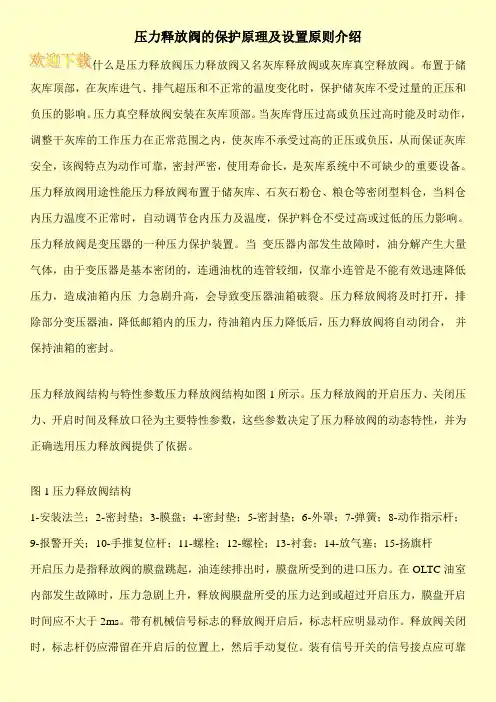
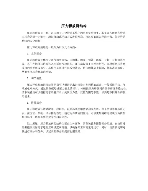
压力释放阀结构与特性参数压力释放阀结构如图1所示。
压力释放阀的开启压力、关闭压力、开启时间及释放口径为主要特性参数,这些参数决定了压力释放阀的动态特性,并为正确选用压力释放阀提供了依据。
图1压力释放阀结构1-安装法兰;2-密封垫;3-膜盘;4-密封垫;5-密封垫;6-外罩;7-弹簧;8-动作指示杆;9-报警开关;10-手推复位杆;11-螺栓;12-螺栓;13-衬套;14-放气塞;15-扬旗杆开启压力是指释放阀的膜盘跳起,油连续排出时,膜盘所受到的进口压力。
在OLTC油室内部发生故障时,压力急剧上升,释放阀膜盘所受的压力达到或超过开启压力,膜盘开启时间应不大于2ms。
带有机械信号标志的释放阀开启后,标志杆应明显动作。
释放阀关闭时,标志杆仍应滞留在开启后的位置上,然后手动复位。
装有信号开关的信号接点应可靠。
YSH55-8580-130型压力释放阀使用说明书西安西变组件有限公司1.适用范围压力释放阀使用与油浸式变压器等电气设备,用于释放变压器油内部过压力的一种保护装置,当油箱内部压力升高至压力方法的开启压力值时,在2ms内迅速开启,使得油箱内压力很快降低,当降低至阀的关闭压力值时,阀门又可靠关闭,油箱内保持正常压力。
2产品型号编制办法2.1型号组成:Y(压力)S(释放)F(阀门)□(设计序列号)-□(开启压力kPa)/□(配有口径mm)KJ(带信号开关和机械信号)□(特殊环境代号)(注意:特殊环境代号:干热带地区“TA”;湿热地区“TH”;干、湿热带地区2.2型号举例:YSF1-55/130KJTH适用于湿热带地区的配有口径为130mm,开启压力为55kPa,带信号开关和机械信号装置、第一次设计的压力释放阀。
3.基本参数(见表1):表1开启压力35 55 70 85开启压力偏差±5关闭压力不小于19 29.5 37.5 45.5密封压力不小于21 33 42 514、结构和工作原理:4.1 压力释放阀的主要结构型式是外弹簧式,并可带或不带定向导流装置,它的主要部件由弹簧、阀座、弹簧座、阀壳体(罩)、标志杆、信号开关(出现盒)、密封圈等零部件组成。
4.2工作原理压力释放阀是用来保护油浸式变压器等电气设备过压力保护的安全装置,可以避免变压器油箱变形或爆裂。
当油浸式变压器内部发生事故时,油箱内的油被气化,产生大量气体,使得油箱内部压力急剧升高。
此压力如果不及时释放,将造成油箱变形或爆裂。
安装压力释放阀就是当油箱内压力升高到压力释放阀的开启压力时,压力释放阀在2ms内迅速开启,使得油箱内的压力很快降低。
当压力降到压力释放阀的关闭压力值时,压力释放阀又可靠关闭,使得油箱内永远保持正压,有效地防止外部空气、水气及其他杂质进入油箱;在压力释放阀开启同时,标志杆向上动作且明显伸出顶盖,表示压力释放阀已动作过,在压力释放阀关闭时,标志杆仍滞留在开启后的位置上,然后必须由手动才能复位。
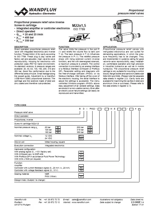
Wandfluh AG Tel. +41 33 672 72 72 E-mail: ******************Illustrations not obligatoryData sheet no.PostfachFax +41 33 672 72 12 Internet: Data subject to change 2.3-562E 1/4 CH-3714 Frutigen Edition 17 01TYPE CODEB D IPM22 --/ M E-#Pressure relief valve Direct operated Proportional, inverse Screw-in cartridge M22x1,5Nominal pressure rang p N 20 bar 20 200 bar 200 100 bar 100 315 bar 315160 bar 160 350 bar 350Nominal voltage U N 12 VDC G1224 VDCG24Slip-on coilMetal housing, square Execution connectionIntegrated electronicsHardware configurationWith analog signal (0…+10 V factory set)A1With CANopen acc. to DSP-408C1With Profibus DP in accordance Fluid Power Technology P1With CAN J1939 (on request) J1Function AmplifierController with current feedback signal (0...20 mA / 4...20 mA) R1Controller with voltage feedback signal (0...10 V) R2Sealing material NBRFKM (Vitron)D1Design-Index (Subject to change)Proportional pressure relief valve inverse Screw-in cartridge• Integrated amplifier or controller electronics • Direct operated• Q max = 20 and 25 l/min • p max = 400 bar • p N max = 350 barDESCRIPTIONDirect operated proportional pressure relief valve with integrated electronics and inverse function. Thread M22x1,5 for cavity according to ISO 7789. These plug & play valves are factory set and adjusted. High valve-to-valve reproducibility. Housing for electronics with protection class IP67 for harsh environment. As standard versions, 6 pressure ranges are available: 20, 40, 63, 100, 160, 200, 315 and 350 bar. Good flow performance due to the differential area principle. Small leakage along the poppet guide. Adjustment by a Wandfluh (VDE-Norm 0580) proportional solenoid. The cartridge and the solenoid made of steel are zinc coated and therefore rust-protected.FUNCTIONThe valve limits the pressure in the port P (1) and reliefs the volume flow to tank port T (2). The back pressure in T (2) influences the pressure in P (1). The reliefed pressure drops with rising solenoid current (inverse function), and the with deenergised solenoid, a maximum pressure is present. The control connection is provided by an analog interface or a fieldbus interface (CANopen or Profibus DP). Parameter setting and diagnosis with the free-of-charge software «PASO» or via fieldbus interface. After taking off the cover of the electronic housing, the serial interface to adjust the settings is accessible. The menu controlled Windows program «PASO» allows easy adjustment of all variable settings. Data are stored in a non-volatile memory. Even after an electric power failure settings can easily be reproduced and transmitted.APPLICATIONProportional pressure relief valves with inte-grated electronics are well suited for demanding applications, in which the pres-sure frequently has to be changed. They are implemented in systems calling for good valve-to-valve reproducibility, easy installati-on, comfortable operation and high precision in industrial hydraulics as well as in mobile hydraulics. The proportional pressure relief catridge is very suitable for mounting in control blocks, flange bodies and sandwich plates size NG4-Mini and NG6. (Please note the separate data sheets in register 2.3). Cavity tools are available for machining the cavities in steel and aluminium (hire or purchase). Please refer to the data sheets in register 2.13.M22x1,5ISO 7789Wandfluh AG Tel. +41 33 672 72 72 E-mail: ******************Illustrations not obligatory Data sheet no.Postfach Fax +41 33 672 72 12 Internet: Data subject to change 2.3-562E 2/4CH-3714 FrutigenEdition 17 01SYMBOL37s3M22x1.5T(2)X1X2X4 (nur Regler)(controller only)35.583X1X3X225,30501821, 2240706s613M DELECTRICAL SPECIFICATIONSProtection class IP 67 acc. to EN 60 529with suitable connector and closedelectronics housingSupply voltageRampsParameterisationInterfaceAnalog interface:Mating connectorPreset value signalFieldbus interface:Device receptaclesupply (male)Mating connectorDevice receptacleCANopen (male)Mating connectorDevice receptacleProfibus (female)Mating connectorPreset value signalFeedback signal interface (Sensor):(controller only)Device receptacle (female) M12, 5-polesMating connector Plug (male), M12, 5-poles(not incl. in delivery)Feedback signal:: Voltage / current state when orderingCONNECTOR WIRING DIAGRAMAnalog interface:Supply voltage +Supply voltage 0 VDCStabilised output voltagePreset value voltage +Preset value voltage -Preset value current +Preset value current -Reserved for extensionsReserved for extensionsEnable control (Digital input)Preset value voltage (PIN 4/5) resp. current (PIN 6/7) are selected withV), (PIN 4/5)Parameterisation interface (USB, Mini B) X2Under the closing screw of the housing coverFeedback signal interface (Sensor)Device receptacle (female) X4 (only controller)1 = Supply voltage (output) +2 = Feedback signal +3 = Supply voltage 0 VDC4 = not connected5 = stab. output voltage2 = Reserved for extensionsDevice receptacle Device receptacleCANopen (male) X3 Profibus (female) X3CAN PROFIBUS1 = not connected 1 = VP2 = not connected 2 = RxD / TxD - N3 = CAN Gnd 3 = DGND4 = CAN High 4 = RxD / TxD - P5 = CAN Low 5 = Shield31452123543145212354123451234123431452HYDRAULIC SPECIFICATIONSFluid Mineral oil, other fluids on requestContamination ISO 4406:1999, class 18/16/13efficiency (Required filtration grade ß 6…10≥75)see data sheet 1.0-50/2Viscosity range 12 mm2/s…320 mm2/sFluid temperature -20…+70°CPeak pressure pmax= 400 barNominal pres. ranges pN= 20 bar, 100 bar, 160 bar, 200 bar,315 bar, 350 barMin. volume flow Qmin= 0,1 l/minMax. volume flow Qmax= 25 l/min for pN=20 bar / 100 bar /160 bar / 200 barQmax= 20 l/min for pN= 315 barQmax= 5 l/min for pN= 350 barLeakage volume flow see characteristicsRepeatability ≤ 3 %Hysteresis ≤ 5 %GENERAL SPECIFICATIONSDescription Direct operated proportional pressure reliefvalve with integrated electronics inverse functionConstruction Screw-in cartridge for cavity acc. to ISO 7789Operations Proportional solenoid wet pin push type,pressure tightMounting Screw-in thread M22x1,5Ambient temperature -20…+65°C (typical)(The upper temperature limit is a guideline value for typicalapplications, in individual cases it may also be higher or lower.The electronics of the valve limit the power in case of a toohigh electronics temperature. More detailed information can beobtained from the operating instructions «DSV».)Mounting position any, preferably horizontalFastening torque MD= 50 Nm for screw-in cartridgeMD= 5 Nm for knurled nutWeight m = 1,0 kgWandfluh AG Tel. +41 33 672 72 72E-mail: ******************Illustrations not obligatoryData sheet no.PostfachFax +41 33 672 72 12 Internet: Data subject to change 2.3-562E 3/4 CH-3714 FrutigenEdition 17 01CHARACTERISTICS Oil viscosity υ = 30 mm 2/s p = f (Q) Pressure volume flow characteristics (Maximum adjustable pressure)p= f (Q) Pressure volume flow characteristics (Minimum adjustable pressure)Q L = f (p)Leakage volume flow characteristicsp red = f (l) Pressure adjustment characteristics[at Q = 10 l/min] / (s corresponds to preset value signal)p = f (l) Pressure adjustment characteristics [at Q = 5 l/min] /(s corresponds to preset value signal)NOTE!Detailed electrical characteristics and description of «DSV » electronics are shown on data sheet 1.13-76.START-UPFor DSV amplifiers as a rule no parameter settings by the customer are required. The plugs have to be connected in accordance with the chapter «Pin assignment».Controllers are supplied configured as amplifiers. The setting of the mode of control and the setting of the controller are done by the customer by software setting (USB interface, Mini B).Additional information can be found on our website:«»Free-of-charge download of the «PASO»-software and the instruction manual for the «DSV » hydraulic valves as well as the operation instruc-tion CANopen eg.Profibus DP protocol with device profile DSP-408 for «DSV ».NOTE!The mating connectors and the cable to adjust are settings is not part of the delivery. Refer to chapter «Accessories».Factory settings:Dither set for optimal hysteresis= Deadband: Solenoid switched offwith command preset value signal <5 % p Nmechanicallly pre-set at Q = 5 l/min= Limited pressure in port P (1) at 70 % of preset value signal: 95 bar with pressure range 350 bar 65 bar with pressure range 315 bar 56 bar with pressure range 200 bar 32 bar with pressure range 160 bar 25 bar with pressure range 100 bar 4 bar with pressure range 20 bar0 10 20 30 40 50 60 70 80 90 100s [%]p [bar]4003002001000 10 20 30 40 50 60 70 80 90 100s [%]p [bar]1209060300p = f (l) Pressure adjustment characteristics [at Q = 5 l/min] / (s corresponds to preset value signal)40030020010000 5 10 15 20 25Q [l/min]p [bar]N = 200 bar N = 160 bar N = 100 bar N= 20 bar504030201000 5 10 15 20 25Q [l/min]403020100 50 100 150 200 250 300 350 p [bar]Q [cm 3/min]0 10 20 30 40 50 60 70 80 90 1001251007550250I [%]p [%]Wandfluh AG Tel. +41 33 672 72 72 E-mail: ******************Illustrations not obligatoryData sheet no.PostfachFax +41 33 672 72 12 Internet: Data subject to change 2.3-562E 4/4 CH-3714 Frutigen Edition 17 01Cavity drawing according to ISO 7789–22–02–0–98For detailed cavity drawing and cavity toolssee data sheet 2.13-1003With fieldbus interface Amplifier With fieldbus interface ControllerDIMENSIONS / SECTIONAL DRAWINGS*Adjusting screw for setting the nominal pressure (-20 % / +30 %)With analog interface Amplifier and ControllerACCESSORIES • Cartridge built in:flange and sandwich bodies see register 2.3• Set-up softwaresee start-up• Cable to adjust the settings through interface USB (from plug type A to Mini B, 3 m) article no. 219.2896• Cable connector for analog interface: – straight, soldering contact article no. 219.2330 – 90°, soldering contact article no. 219.2331Recommended cable size: – Outer diameter 9…10,5 mm – Single wire max. 1 mm 2 – Recommended wire size: 0…25 m = 0,75 mm 2 (AWG18) 25…50 m = 1 mm 2 (AWG17)Technical explanation see data sheet 1.0-100PARTS LIST Position Article Description17160.2187O-ring ID 18,72 x 2,62 (NBR)18160.2170O-ring ID 17,17 x 1,78 (NBR)20154.2700Knurled nut21223.1317Dummy plug M16 x1,522160.6131O-ring ID 13,00 x1,525062.0102Cover square 30072.0021Gasket 33,2 x 59,9 x 240208.0100Socket head cap screw M4 x1050160.2188160.6188O-ring ID 18,77 x 1,78 (NBR)O-ring ID 18,77 x 1,78 (FKM)60160.2140160.6141O-ring ID 14,00 x 1,78 (NBR)O-ring ID 14,00 x 1,78 (FKM)70049.3177Back-up ring RD 14,6 x 17,5 x 1,4353790.2s 30M 22x 1.5T(2)X2X1X3X4172.4P(1).5(1)E: Venting。

![压力释放阀说明书[中英]](https://uimg.taocdn.com/2e96aecc76c66137ef06192d.webp)
压力释放阀PRESSURE RELEASE VALVE使用说明书OPERATION INSTRUCTION明远电器设备SHENYANG MINGYUAN ELECTRIC EQUIPMENT CO., Ltd.本说明书适用于我公司生产的系列变压器用压力释放阀,阐述其用途、性能、规格、技术参数、使用及安装,供用户参考。
The Operation Instruction is applicable to pressure release valve of a series of transformers manufactured by our company, indicating its application, performances, specifications, technical parameters, usage and installation for uses’ reference.1. 压力释放阀用途和性能压力释放阀适用于油浸式电力变压器、电力电容器及有载分接开关等,用来保护油箱。
当油浸式变压器在运行中出现故障时,由于线圈过热,使一部分变压器油汽化,变压器油箱中压力迅速增加,这时压力释放阀在2ms迅速动作,释放压力,保护油箱不致变形或爆裂。
油箱的压力再升高而达到开启压力时,压力释放阀应再次动作,直到油箱的压力降到正常值。
由于压力释放阀动作后能可靠关闭,油箱外的水和空气不能进入油箱,变压器部不会受大气污染。
1.Application and performancePressure release valves play a vital role in the protection of oil-immersed electrical equipments, such as transformers, high voltage switch gears, capacitor and on load tap-changers, etc. This device can prevent the oil-immersed electrical equipment from deformation or rupture. Should a fault occur in such electrical equipment, from deformation of rupture? Should a fault occurring in such electrical equipment, they are instantaneously vaporize the oil causing extremely rapid build-up of gaseous pressure? If mounting this type pressure release device on the oil-tank, when the pressure reaches to its opening pressure, it opens automatically within 2ms and relieves the pressure.2.型号、规格及基本参数Type, specification and technical parameters2.1 型号的含义 Meaning of typeY S F□—□ / □□□特殊环境代号(Special environment)带机械信号标“J”(“J”:mechanical signal)带信号开关标“K”(“K”:electrical signal)两者都带标“KJ”(“KJ”:Both with signal)喷油有效口径(Caliber of oil-gushing tube)mm开启压力(Opening pressure)kPa设计序号(Design serial number)阀(valve)释放(release)压力(pressure)注:特殊环境代号 note: special environment:TA: 干热带地区 dry tropicTH: 湿热带地区 humid tropicT: 干、湿热带地区 dry、humid tropic例:YSF16-55/130KKJT开启压力为55kPa,喷油口径为φ130mm,带电信号、机械信号。
压力释放阀结构
压力释放阀是一种广泛应用于工业管道系统中的重要安全设备,其主要作用是在管道
内压力达到一定值时,通过自动或手动方式进行开启,将过高的压力释放出来,保证管道
系统的安全运行。
压力释放阀的结构一般分为以下几个方面:
1. 主体部分
压力释放阀主体部分通常由外阀体、内阀体、阀座、弹簧、隔膜、导杆、导杆座等组成。
其中外阀体与内阀体之间采用密封结构,在内部设置了压差控制件。
隔膜则是压力释
放阀的重要组成部分,其作用是通过气压或弹簧力,将内阀体向上推动,使其离开阀座,
从而实现压力释放的功能。
2. 调节装置
压力释放阀的调节装置是指可以根据需求进行设定和调整的部分。
一般采用手动、气
动或电动方式,通过调节螺母或压力表上的指针,来确保压力释放阀的调节精度和稳定性。
调节装置还可以根据需求设置开启/关闭压力值、流量范围等参数,以满足不同场合的使
用需求。
3. 附件部分
压力释放阀还需要配备一些附件,以提高其使用效果和安全性。
常见的附件包括压力表、溢流管、挡板、讯号捕捉器等,通过附件的协同作用,可以更加精准地实现压力的控
制和释放,提高系统的安全性和稳定性。
综上所述,压力释放阀的结构主要由主体部分、调节装置和附件部分组成。
在使用时
需要根据实际需求进行正确设置和调整,以确保其正常稳定地运行。
同时,还需要定期对
其进行维护和保养,以延长其寿命并提高使用效果。
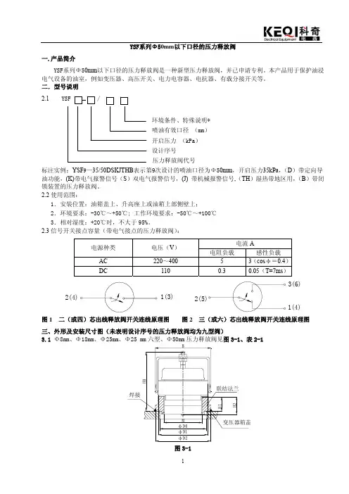
YSF系列Ф50mm 以下口径的压力释放阀一.产品简介YSF系列Ф50mm 以下口径的压力释放阀是一种新型压力释放阀,并已申请专利。
本产品用于保护油浸电气设备的油室,例如变压器、高压开关、电力电容器、电抗器、有载分接开关等。
二.型号说明2.1 YSF环境条件、特殊说明* 喷油有效口径 (mm) 开启压力 (kPa) 设计序号 压力释放阀代号标注实例:YSF 9—35/50DSKJTHB 表示第9次设计的喷油口径为Ф50mm ,开启压力35kPa ,(D )带定向导油功能,(K)带电气报警信号(S )双电气报警信号,(J) 带机械报警信号,(TH )湿热带地区用,(B )带闭锁装置的压力释放阀。
2.2使用范围:1.安装位置:油箱盖上、升高座上或油箱上部侧壁上;2.环境要求:-30℃~+50℃; 工作环境要求:-50℃~+100℃ 3.相对湿度:+20℃时,不大于95%。
2.3信号开关接点容量(带电气接点的压力释放阀):图1 二(或四)芯出线释放阀开关连线原理图 图2 三(或六)芯出线释放阀开关连线原理图 三、外形及安装尺寸图(未表明设计序号的压力释放阀均为九型阀)3.1 Φ8mm、Φ18mm、Φ25mm、Φ25 mm 六型、Φ50mm 压力释放阀见图3-1、表2-1图3-1电流A电源种类 电压(V )电阻负载 感性负载 AC 220~400 5 3(cos φ=0.4)DC 110 0.3 0.05(T=7ms )1(4)3(6)2(4)单位mm 表2-1型号 D0 D1 D2 H0 H1 H2 B MФ8 16 22 46 14 18 M14×1Ф18 49 54 59 85 16 19 62 M42×3 Ф2555 62 68 95 18 22 70 M48×3 Ф25(六型)40 54 54 87 18 21 62 M38×2Ф5093 100 105 100 22 28 112 M80×33.2 Ф25K、Ф50K 压力释放阀见图3-2、表2-2图3-2单位mm 表2-2 型号D0 D1 D2 H0 H1 H2 A M Ф25KJB 55 80 68 103 18 22 55 M48×3Ф50KJB 93 115 105 120 22 28 75 M80×33.3 Ф50DK 压力释放阀见图3-3;图3-33.4 Ф25K四型阀见图3-4,Ф50K四型阀见图3-5,Ф25DK四型阀见图3-6,Ф50DK四型阀见图3-7;图 3-4图 3-5。
压力释放阀的功用
压力释放阀是一种安全装置,广泛应用于各种系统中,其主要功用是在系统压力超过设定值时,自动释放过量的压力,以保护系统免受压力过高的损害。
这种阀门在各种工业设备中都有广泛的应用,尤其是在变压器这类设备中更是不可或缺。
在变压器中,压力释放阀的主要作用是防止油箱变形或爆裂。
当变压器内部发生故障,如电弧或过流产生的热量使油发生分解,会产生大量高压气体,导致油箱内部压力急剧升高。
如果这种压力不及时释放,可能会造成油箱变形甚至爆裂,从而引发更严重的安全事故。
而压力释放阀就是设计来应对这种情况的,它会在压力达到设定值时迅速打开,释放部分变压器油和气体,从而降低油箱内的压力。
待压力降低到安全范围后,压力释放阀又会自动关闭,保持油箱的密封状态。
压力释放阀的构造通常由阀盖、上阀体、下阀体、挡环、弹簧、真空环、隔膜垫等组成。
其工作原理主要是依靠弹簧的弹力和系统内压力的平衡来控制阀门的开启和关闭。
当系统内压力超过弹簧的预设值时,阀门就会被顶开,释放过量的压力。
当压力下降到设定值以下时,弹簧的弹力又会使阀门关闭,保持系统的正常运行。
总的来说,压力释放阀在保护变压器等设备的安全运行中起着至关重要的作用。
它能有效地防止因系统压力过高而引发的安全事故,提高设备的使用寿命和稳定性。