科尔摩根MK40操作指南
- 格式:pdf
- 大小:957.29 KB
- 文档页数:22


LUMENS1350LUMENS2800LUMENS550LUMENS4015min 2h15min 45min 30h289m (Beam Distance)21,000cd (Peak Beam Intensity)IPX-8, 2m (Waterproof AND Submersible)1.5m (Impact Resistant)1×18650®User ManualFeaturesUtilizes a CREE XHP70 LEDDriven by a dedicated IMR 18650 battery to emit up to 2,800 lumens brightness Ultra-bright dual-mode tactical blazeDual-switch tail cap designed for tactical use and easy application Mode 1 Suppressing light: Direct access to turbo modeMode 2 STROBE READY TM: Direct access to Strobe Mode (Chinese Patent:201320545349.4) Four easily accessible brightness levels and memory function for fast boost Maximum beam intensity up to 21,000cd Extensive runtime up to 30 hours 289 meters far throwIntegrated metal micro textured reflector for optimal peripheral illuminationA power indicator LED hidden in the tail switch indicates battery power (Chinese patent: ZL201220057767.4)Electric reverse polarity protection Temperature regulation and protection Anti-rolling designToughened ultra-clear mineral glass with anti-reflective coating Constructed from aero grade aluminum alloy Robust HAIII military grade hard-anodizedWaterproof in accordance with IPX-8 (two meters submersible)DimensionsLength: 6.25” (159mm)Head Diameter: 1.57”(40mm)Tail Diameter: 1.18” (30mm)Weight: 7.52oz (213g)(without battery)Accessories1xNI18650D dedicated battery (for TM03 only), O-ring, holster *The dedicated NI18650D battery can be purchased seperately.Battery TypeThe TM03 uses a dedicated Nitecore IMR 18650 Li-ion rechargeable battery.Brightness & RuntimeThanks for purchasing NITECORE!The All-Round Flashlight ExpertOperating InstructionsBattery InstallationInstall a dedicated IMR 18650D battery with the positive end pointing inward.Note: The tail cap indicator LED will blink to indicate battery power upon battery installation. Please refer to Power Tips for details.Tactical Momentary IlluminationPress the tail switch partway to turn on the flashlight, and release to turn it off.On/Off OperationTo turn the TM03 on, press the tail switch until a “click” is heard. To turn the TM03 off, press the tail switch again until a “click” is heard.Brightness LevelsWith the TM03 turned on, press the MODE switch to cycle through power levelsLow-Medium-High-Turbo. The TM03 has memory for brightness levels. When it is switched on, the TM03 will enter the brightness level last used.Mode SelectionThe TM03 has two special modes: Suppressive Light mode (Mode 1) and STROBE READY™ mode (Mode 2). To switch between these modes, follow the procedure below: Step 1: With the TM03 turned off, remove and replace the battery;Step 2: Within 60 seconds of completing step 1, tighten the TM03's tail switch while pressingTM03SYSMAX Industry Co., Ltd.TEL: +86-20-83862000 FAX: +86-20-83882723 E-mail: *****************Web: Address : Rm1401-03, Glorious Tower, 850 East Dongfeng Road,Guangzhou, China 51060020160606Please find us on facebook: NITECORE Flashlightsand holding the MODE switch;Step 3: Upon completing step 2, the mode will be indicated as follows: : one flash whenSuppressive Light mode (Mode 1) is selected, and two flashes when STROBE READY TMmode (Mode 2) is selected.Note: Mode selection will be unavailable when battery voltage is below 3.7V.Suppressing Light Mode (Mode 1)Direct access to turbo: In any setting of the TM03, including power-off, press and hold the MODE switch for over 0.2 second to access turbo brightness, and release to resume previous setting.Quick access to strobe: In any setting of the TM03, including power-off, press the MODE switch twice in quick succession to access strobe mode, and press again to resume previous setting.STROBE READY TM Mode (Mode 2)Direct access to strobe: In any setting of the TM03, press and hold the MODE switch for over 0.2 second to access strobe mode, and release to resume previous setting.Quick access to turbo: In any setting of the TM03, press the MODE switch twice in quick succession to access turbo mode, and press again to resume previous setting.Temperature Regulation and ProtectionThe TM03 features temperature regulation and protection. It automatically monitors its internal temperature in high and turbo levels. When its body temperature is higher than 50°C, the TM03 will automatically lower its brightness. When its body temperature drops below 50°C, the TM03 will gradually increase its brightness to high level.Power TipsUpon battery installation, the red power indicator LED in the tail switch will blink to indicate battery power:1. Three blinks indicate power levels above 50%;2. Two blinks indicate power levels below 50%;3. One blink indicates power levels below 10%.Changing BatteryWhen the battery power is insufficient, the output appears to be dim or the flashlight becomesirresponsive. When the battery is close to depletion, the main LED will flicker until it completely goes off. In either condition, the battery should be replaced.Precautions1. Do not install a battery with polarity reversed. Otherwise the TM03 could not work.2. In Mode 1, after several consecutive turbo boosts, the battery voltage may be insufficient for further turbo boosts. This is considered normal.3. Installing ordinary 18650 Li-ion batteries or other IMR 18650 batteries will compromise some functions of the TM03.4. Charge the NI16850D battery dedicated to TM03 with Nitecore chargers or other qualified and authentic chargers only.5. Ensure the positive polar of the NI16850D battery dedicated to TM03 is in full contact with charger’s pins when charging. Otherwise the charging can fail, or the battery will go short-circuit.6. The standby time for the TM03 is approximately one year.7. Do not direct beam into eyes as doing so can damage vision.8. Keep small parts in the package away from children to avoid choking.9. Do not dismantle, remodel or handle the TM03 in any improper way. Doing so will void your warranty.Warranty DetailsOur authorized dealers and distributors are responsible for warranty service. Should any problem covered under warranty occurs, customers can contact their dealers or distributors in regards to their warranty claims, as long as the product was purchased from an authorized dealer or distributor. NITECORE’s Warranty is provided only for products purchased from an authorized source. This applies to all NITECORE products.Any DOA / defective product can be exchanged for a replacement through a local distributor/dealer within the 15 days of purchase. After 15 days, all defective / malfunctioning NITECORE® products can be repaired free of charge for a period of 60 months (5 years) from the date of purchase. Beyond 60 months (5 years), a limited warranty applies, covering the cost of labor and maintenance, but not the cost of accessories or replacement parts.The warranty is nullified if the product(s) is/are broken down, reconstructed and/or modified by unauthorized parties, or damaged by batteries leakage.For the latest information on NITECORE® products and services, please contact a local NITECORE® **********************************************.※All images, text and statements specified herein this user manual are for reference purpose only. Should any discrepancy occurs between this manual and information specified on . Sysmax Industry Co., Ltd. reserves the rights to interpret and amend the content of this document at any time without prior notice.00NOTICEThe above data has been measured in accordance with the international flashlight testing standards ANSI/NEMA FL1 using 1x Nitecore NI18650D (3.6V, 11.2Wh, dedicated for TM03 only) battery under laboratory conditions. The data may vary slightly during real-world use due to battery type, individual usage habits and environmental factors.The Turbo mode of the TM03 WILL NOT be operational when powered by other standard 18650, IMR18650 or CR123 batteries.。


使⽤说明书数码照相机本说明书中的常⽤指⽰符号本说明书中使⽤了下列符号。
2CHS⽬录快速任务索引7各部位名称 10使⽤前的准备⼯作 12查验包装内的物品 (12)电池充电和插⼊电池 (13)插⼊存储卡 (14)取出存储卡 (14)安装照相机镜头 (15)打开电源 (16)⽇期/时间设定 (17)拍摄 18拍摄时的信息显⽰ (18)拍摄时的显⽰屏显⽰内容 (18)在不同显⽰间切换 (20)在使⽤实时取景拍摄和取景器拍摄之间切换 (20)切换信息显⽰ (21)拍摄静⽌图像 (22)使⽤iAUTO模式 (24)在场景模式下拍摄 (26)使⽤创意拍摄 (28)使⽤PHOTO STORY (30)“即取即拍”摄影(P程序式模式) (32)选择光圈(A光圈优先模式) (33)选择快门速度(S快门优先模式) (34)选择光圈和快门速度(M⼿动模式) (35)长时曝光拍摄(BULB) ...........35实时合成摄影(暗光和亮光区域合成) (36)操作触摸屏来拍摄 (37)记录视频 (38)使⽤视频模式(n) (39)在视频记录过程中拍摄照⽚(影⽚+照⽚模式) (40)拍摄视频时使⽤静⾳功能 (40)拍摄“我的剪辑” (41)编辑“我的剪辑” (42)拍摄快慢镜头视频 (43)记录⾼速视频 (44)使⽤拍摄选项 (45)调⽤拍摄选项 (45)控制曝光(曝光补偿) (47)锁定曝光(AE锁定) (47)设置AF焦点(⾃动对焦区域) (48)使⽤⼩焦点和群组焦点(设定AF焦点) (48)脸部识别AF/瞳孔识别AF (49)缩放框AF/缩放AF(超级点AF) (50)选择对焦模式(AF模式) (51)更改⾼光显⽰和阴影显⽰的亮度 (52)控制颜⾊(⾊彩创造) (52)选择照相机测量亮度的⽅法(测光) (53)ISO感光度 (53)调整⾊彩(⽩平衡) (54)微调⽩平衡(⽩平衡补偿) (55)减轻照相机晃动(影像防抖) (56)连拍/使⽤⾃拍定时器 (57)拍摄时快门按钮操作不造成振动影响(快门减震z) (58)3CHS4CHS⽬录拍摄时不发出快门声⾳(静⾳[♥])..............................58设定图像宽⾼⽐.....................59选择画质(静⽌图像画质模式) ..............60选择画质(视频画质模式) ........61使⽤闪光灯(闪光摄影) ...........62调整闪光输出(闪光补正) ........64指定按钮功能(按钮功能) ........64处理选项(影像模式) ..............68微调清晰度(清晰度) ..............69微调对⽐度(对⽐度) ..............69微调彩度(饱和度) ..................69微调⾊调(灰阶).....................70设定颜⾊再现格式(⾊彩空间) ...........................71视频声⾳选项(记录有声视频).....................72将效果添加⾄视频 (72)74播放期间的信息显⽰ .................74播放图像信息 ........................74切换信息显⽰ ........................75查看照⽚和视频........................76索引显⽰/⽇历显⽰ ..............77查看静⽌图像 ........................77⾳量 .....................................78观看视频 ..............................79保护图像 ..............................79删除图像 ..............................79对图像设定传输预约([预约分享]) .........................80选择图像([预约分享选定]、[0]、[删除所选张]) .............80使⽤触摸屏 ..............................81选择和保护图像.....................8182基本菜单操作...........................82使⽤拍摄菜单1/拍摄菜单2 (83)格式化插卡(设定存储卡) ........83删除所有图像(设定存储卡).....83恢复到默认设定(重设) ...........84保存喜好设定(⾃定义设定).....84处理选项(影像风格) ..............85图像质量(K ) ......................85数码变焦(数码远摄转换器).....86设定⾃拍定时器(j /Y ) ........86以固定间隔⾃动拍摄(i 间隔拍摄).......................87更改⼀系列照⽚的设定(包围拍摄) ...........................88拍摄HDR (⾼动态范围)图像 .....................................91将多次曝光记录为单张图像(多重曝光) ...........................92梯形失真校正和透视控制(梯形失真补偿).....................93设定快门减震/静⾳拍摄(快门减震z /静⾳[♥]) ........94⽆线遥控闪光摄影 ..................94使⽤播放菜单...........................95显⽰旋转的图像(R ) .............95编辑静⽌图像 ........................95取消所有保护 ........................97使⽤设定菜单...........................98X (⽇期/时间设定) .............98W (更改显⽰语⾔) .............98i (显⽰屏亮度调节) ...........98照⽚⾃动回放 ........................98Wi-Fi 设定 ............................98c ⾼级菜单显⽰ ....................98固件 . (98)⽬录使⽤⾃定义菜单 (99)R AF/MF (99)S按键/拨盘 (100)T快门释放/连拍 (100)U显⽰/提⽰⾳/PC (101)V曝光/测光/ISO (103)W闪灯设定 (104)X画质/⾊彩/WB (104)Y记录/删除 (105)Z动画 (106)b内置 EVF (108)k相机设定 (108)AEL/AFL (109)⼿动辅助对焦 (110)在电视机上查看照相机图像 (110)选择控制⾯板显⽰(K相机操控设定) (112)添加信息显⽰ (113)⾃动闪光时的快门速度 (114)组合使⽤动态影像尺⼨和压缩率 (114)选择取景器的显⽰样式 (115)116连接智能⼿机 (117)将图像传输到智能⼿机 (118)使⽤智能⼿机遥控拍摄 (118)添加位置信息到图像 (119)改变连接⽅法 (120)更改密码 (120)取消预约分享 (121)初始化⽆线LAN设定 ..............121122将照相机连接到电脑 (122)将照⽚复制到电脑 (122)安装电脑软件 (123)直接打印(PictBridge) (125)简单打印 (125)⽤户⾃定义打印 (126)打印预约(DPOF) (127)创建打印预约 (127)从打印预约中删除所有或已选图像 (128)129电池与充电器 (129)在国外使⽤充电器 (129)⽀持的插卡 (130)记录模式和图像尺⼨/可存储静⽌图像数 (131)132133专⽤于本照相机的外部闪光灯 (133)⽆线遥控闪光摄影 (133)其它外接闪光灯 (134)主要附件 (135)系统图 (136)5CHS⽬录138拍摄提⽰与信息 (138)错误代码 (140)清洁和存放照相机 (142)清洁照相机 (142)存储 (142)清洁和检查摄像设备 (142)像素映射 -检查图像处理功能 (143)菜单索引 (144)默认的⾃定义设定选项 (151)规格 (153)156安全事项 (156)1636CHS速任务索引7 CHS快速任务索引8CHS快速任务索引9 CHS10CHS各部位名称1 模式拨盘 .................................第22页2 后拨盘*(o )第32 – 35、46 – 47、61、66 – 67、76页3 R (视频)/H 按钮...........................第38、64页/第80页4 Fn2按钮 ..................第52、64、66页5 快门按钮 .................................第23页6 背带安装环 ..............................第12页7 前拨盘*(r )第32 – 35、46 – 47、61、66 – 67、76页8 镜头连接标志 (15)9 镜头卡⼝(请在安装镜头前取下防尘护盖。
布鲁克兆核磁操作使⽤指南布鲁克400兆核磁氢谱操作使⽤指南1.氢谱——进⼊到topspin操作界⾯,⽤⾼度量桶准确量测核磁管⾼度后,键⼊ej命令,⽓体⾃动吹出,等到感觉⽓体⽓流最⼤时,放⼊样品,然后在topspin界⾯上,键⼊ij命令,样品⾃动下滑到探头位置。
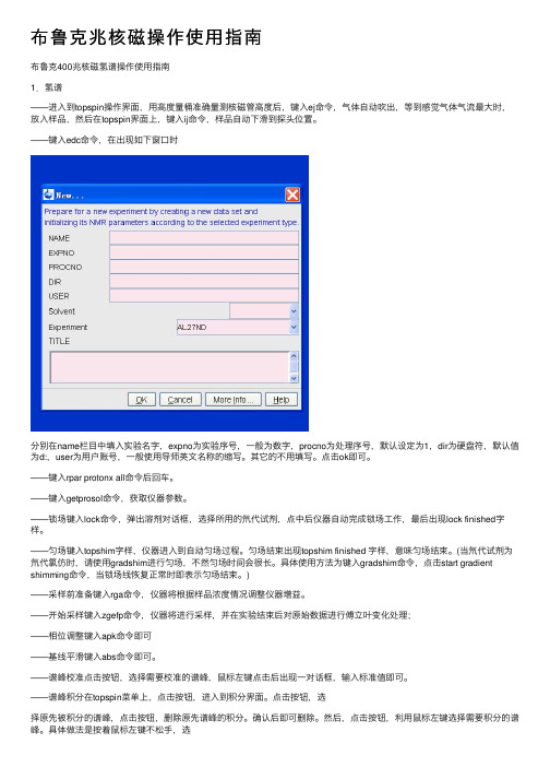
——键⼊edc命令,在出现如下窗⼝时分别在name栏⽬中填⼊实验名字,expno为实验序号,⼀般为数字,procno为处理序号,默认设定为1,dir为硬盘符,默认值为d:,user为⽤户账号,⼀般使⽤导师英⽂名称的缩写。
其它的不⽤填写。
点击ok即可。
——键⼊rpar protonx all命令后回车。
——键⼊getprosol命令,获取仪器参数。
——锁场键⼊lock命令,弹出溶剂对话框,选择所⽤的氘代试剂,点中后仪器⾃动完成锁场⼯作,最后出现lock finished字样。
——匀场键⼊topshim字样,仪器进⼊到⾃动匀场过程。
匀场结束出现topshim finished 字样,意味匀场结束。
(当氘代试剂为氘代氯仿时,请使⽤gradshim进⾏匀场,不然匀场时间会很长。
具体使⽤⽅法为键⼊gradshim命令,点击start gradient shimming命令,当锁场线恢复正常时即表⽰匀场结束。
)——采样前准备键⼊rga命令,仪器将根据样品浓度情况调整仪器增益。
——开始采样键⼊zgefp命令,仪器将进⾏采样,并在实验结束后对原始数据进⾏傅⽴叶变化处理;——相位调整键⼊apk命令即可——基线平滑键⼊abs命令即可。
——谱峰校准点击按钮,选择需要校准的谱峰,⿏标左键点击后出现⼀对话框,输⼊标准值即可。
——谱峰积分在topspin菜单上,点击按钮,进⼊到积分界⾯。
点击按钮,选择原先被积分的谱峰,点击按钮,删除原先谱峰的积分。
确认后即可删除。
然后,点击按钮,利⽤⿏标左键选择需要积分的谱峰。
具体做法是按着⿏标左键不松⼿,选择需要积分的谱峰后松⼿,积分即可完成。
扭矩分析仪快速入门指南测量界面首先自动选择上一次使用的测量模式(Peak、Click、Track或Pulse)。
可按下“测量模式”(Measurement Mode)功能键对此进行更改。
按动该功能键可切换不同测量模式,直到出现您需要的模式,然后即可使用设备开始测量扭矩。
3测量适配器插座LED白色OLED显示屏功能软键标准测量适配器“确认”键方向箭头键电源按钮Cleco扭矩分析仪 - 固定功能键图标以下提供设备上出现的固定功能键图标指南:测量模式 默认测量模式是Peak。
按下第二次是Track模式,按下第三次是Click模式,按下第四次是Pulse模式(在辅助参数位置显示图标)。
删除通过该功能键可删除上一次读数或所有读数。
按下一次,会删除上一次读数;按下两次,将删除所有记录。
读取列表 按下该功能键可显示Cleco扭矩分析仪上当前保留的测量读数。
使用向上和向下箭头键可滚动浏览读取的读数。
统计 该功能键可显示以下统计结果(源自当前读数):数量、范围、平均值、最小值、最大值、标准偏差(sigma)以及6 sigma。
设置使用设置功能键可在各种界面设置之间切换。
如需了解更多信息或者需要设置方面的帮助,请参考操作手册。
Cleco扭矩分析仪操作手册有关Cleco扭矩分析仪的更多详细信息,请在我们的网站下载完整的操作手册。
该手册介绍了有关设备的更多信息,包括特性和技术规格、产品设置详情以及清晰易懂的指南,可助力实现高效操作。
测量界面(续)测量界面上不同图标的释义如下:测量模式Cleco扭矩分析仪上出现以下扭矩测量模式:45测量读取主测量模式电池状态或电源指示灯读取的读数数量测量单位持续时间(秒)旋转方向/扭矩Click Peak Track Pulse。
数码多功能复合机M221N用户指南使用说明书在使用本产品之前,请务必先仔细阅读本使用说明书。
请务必保留备用。
请在充分理解内容的基础上,正确使用。
USRM3-0775-00 2021-10 zh目录基本操作 (2)零部件及其功能 (4)外视图 (5)内视图 (8)控制面板 (10)显示屏 (13)自定义 <主页> 画面 (17)登录到本机 (19)使用显示屏 (22)输入文本 (25)放置文档 (27)装入纸张 (31)将纸张装入纸盒 (33)将纸张装入多功能托盘 (37)将信封装入多功能托盘 (40)装入预打印纸张 (43)指定纸张尺寸和类型 (46)注册自定义纸张尺寸 (48)在地址簿中注册 (50)在地址簿中注册接收方 (51)注册单键拨号的接收方 (55)将多个接收方注册为群组拨号 (59)调节音量 (62)进入睡眠模式 (63)复印 (66)基本复印操作 (68)选择复印纸张 (70)取消复印 (71)各种复印设置 (73)放大或缩小 (75)选择文档类型 (76)调整浓度 (77)双面复印 (78)将多个文档复印到一张纸上(2合1/4合1) (81)将 ID 卡的两面复印到一页上 (83)消除黑色边框和框线(消除黑框) (84)按页面分套 (86)将对开页分离为单独页面用于复印 (88)同时复印不同尺寸的文档(不同尺寸的原稿) (89)根据需要配置复印设置 (90)将本机作为打印机使用 (94)从计算机打印 (95)取消打印 (97)检查打印状态 (100)打印通过 PIN 加密的文档(安全打印) (102)通过安全打印进行打印 (103)根据需要配置打印设置 (106)注册常用打印设置组合 (107)更改默认设置 (109)将本机用作扫描仪 (112)将本机用作扫描仪的准备 (113)从本机扫描 (114)从计算机扫描 (117)使用应用程序扫描 (118)配置 ScanGear MF 中的扫描设置 (120)使用 WSD (121)采用单机操作的快捷扫描 (125)将文档作为电子邮件直接从本机发送 (126)将文档直接保存到共享文件夹 (132)取消发送文档(电子邮件/共享文件夹) (135)指定详细设置 (137)指定扫描尺寸 (138)设置色彩模式 (139)选择文件格式 (140)调整浓度 (141)指定文档方向 (142)选择文档类型 (143)扫描双面文档 (144)调整文件尺寸和图像质量之间的平衡 (145)设置 Gamma 值 (146)使用注册的接收方发送(电子邮件/共享文件夹) (147)从地址簿指定 (148)输入编码拨号号码直接选择接收方 (151)指定单键拨号按钮的接收方 (154)指定先前使用的接收方 (156)指定 LDAP 服务器中的接收方(电子邮件) (159)更改默认设置 (163)查看发送文档的状态和日志(电子邮件/共享文件夹) (165)网络 (168)连接至网络 (169)选择有线局域网或无线局域网 (171)使用 WPS 按钮模式设置连接 (175)使用 WPS PIN 代码模式设置连接 (177)通过选择无线路由器设置连接 (180)通过指定详细设置来设置连接 (183)检查 SSID 和网络密钥 (187)设置 IP 地址 (188)设置 IPv4 地址 (189)设置 IPv6 地址 (192)查看网络设置 (196)配置本机从计算机打印 (199)配置打印协议和 WSD 功能 (200)配置打印机端口 (203)设置打印服务器 (206)配置扫描设置(电子邮件/共享文件夹) (209)配置扫描设置(发送电子邮件) (210)配置电子邮件通信设置 (211)配置本机扫描到共享文件夹 (215)针对您的网络环境配置本机 (216)配置以太网设置 (217)更改最大传送单位 (219)设置连接至网络的等待时间 (220)配置 DNS (221)配置 SMB (226)注册 LDAP 服务器 (228)配置 SNTP (234)通过 SNMP 监视和控制本机 (237)安全 (243)防止本机遭受无授权访问 (244)防止未经授权的访问 (245)设置访问权限 (247)设置系统管理员识别码 (248)设置部门识别码管理 (250)设置远程用户界面 PIN (257)LDAP 服务器认证 (259)使用防火墙限制通信 (263)指定用于防火墙规则的 IP 地址 (264)指定用于防火墙规则的 MAC 地址 (268)更改端口号 (271)设置代理服务器 (273)限制本机功能 (275)限制访问地址簿和发送功能 (276)对地址簿设置 PIN (277)限制可用接收方 (278)禁止使用之前使用的接收方 (279)发送文档前检查接收方 (280)限制从计算机打印 (281)限制 USB 功能 (282)禁用 HTTP 通信 (283)禁用远程用户界面 (284)执行可靠的安全功能 (285)对远程用户界面启用 TLS 加密通信 (286)配置 IEEE 802.1X 认证 (289)为密钥对和数字证书配置设置 (294)生成密钥对 (295)使用 CA 发布的密钥对和数字证书 (302)验证密钥对和数字证书 (305)使用远程用户界面 (308)启动远程用户界面 (309)远程用户界面画面 (311)管理文档和查看本机状态 (315)从远程用户界面设置菜单选项 (319)从远程用户界面保存/载入地址簿 (321)从远程用户界面注册地址簿 (325)设置菜单列表 (329)网络设置 (330)参数选择 (340)定时器设置 (345)常规设置 (348)复印设置 (352)扫描设置 (355)打印机设置 (359)调整/维护 (368)系统管理设置 (373)故障排除 (381)清除卡纸 (383)针对每条讯息的应对措施 (398)针对每个错误代码的应对措施 (405)普通问题 (411)安装/设置问题 (413)复印/打印问题 (417)其他问题 (420)无法正确打印时 (421)打印效果不满意 (423)无法解决问题时 (431)保养 (433)清洁本机 (434)外部 (435)稿台玻璃 (436)输稿器 (438)转印辊 (442)感光鼓 (443)定影组件 (444)更换墨粉盒 (446)配置耗材的购买信息 (448)如何更换墨粉盒 (450)打印报告和列表 (453)电子邮件/文件的发送结果报告 (454)通信管理报告 (456)地址簿列表 (457)用户数据列表/系统管理员数据列表 (459)部门识别码管理报告 (460)PCL字体列表 (461)复印/打印费用日志报告 (462)查看计数器数值 (463)初始化设置 (465)初始化地址簿 (466)初始化菜单 (467)初始化系统管理设置 (468)初始化所有数据/设置 (469)更换部件 (470)附录 (472)第三方软件 (473)主要功能 (474)环保省钱 (475)效率更高 (477)数字化 (479)更多特点 (482)规格 (484)主机 (485)输稿器 (双面自动输稿器-AY) (488)可用纸张 (489)单纸盒组件-AD (492)双面组件-C (493)管理功能 (497)系统环境 (498)网络环境 (500)选项 (501)可选设备 (502)系统选项 (504)手册及其内容 (506)查看用户指南 (507)基本 Windows 操作 (508)注意 (515)基本操作基本操作 (2)零部件及其功能 (4)外视图 (5)内视图 (8)控制面板 (10)显示屏 (13)自定义 <主页> 画面 (17)登录到本机 (19)使用显示屏 (22)输入文本 (25)放置文档 (27)装入纸张 (31)将纸张装入纸盒 (33)将纸张装入多功能托盘 (37)将信封装入多功能托盘 (40)装入预打印纸张 (43)指定纸张尺寸和类型 (46)注册自定义纸张尺寸 (48)在地址簿中注册 (50)在地址簿中注册接收方 (51)注册单键拨号的接收方 (55)将多个接收方注册为群组拨号 (59)调节音量 (62)进入睡眠模式 (63)基本操作83AH-000本章说明了本机常用功能的基本操作,例如如何使用控制面板或如何装入纸张和文档。
SGP40 –Quick Testing Guide Version 1.1Stäfa, March 2021SetupThe goal of this quick testing guide is to enable any customer to verify that their Sensirion SGP40sensors are performing according to ing only common household items we can create an accurate dilution series of a volatile organic compound(VOC)that will be sufficient to reach this goal.Required items▪2large bottles(1l or more)▪2bowls▪4small containers(50–200ml)▪Tap water▪Approximately200g of table salt(for keeping the relative humidity constant)▪1teaspoon of ethanol(1)(ca.40%vol.or more)▪Either Sensirion SGP40sensors or SEK-SVM40EvalKit and Control Center Software(running on any conventional computer),also see /my-sgp-ekrequired time:2hours(1) Any hard liquor or rubbing alcohol will do; you can also try some other concentrated VOC source such as nail polish remover,paint thinner or the likeStep one: salt solutionWe first want to prepare a reference solutions for diluting:a saturated salt solution.▪Mix200g of table salt with1l of tap water(room temperature)in one of the bottles▪Shake bottle well and let it settle.A lot of the salt won't be dissolved and deposit at the bottom.This is your salt solution(2)stock.(2) We use a saturated salt solution because its headspace is non-condensing (ca.70% relative humidity) and thus more realistic for mimicking indoor climateStep two: high VOC concentration solutionNext,we prepare a high concentration VOC solution as the starting point of the dilution series.1.In a bowl,mix250ml(1cup)of the salt solution with1teaspoon of ethanol2.Dilute it10:1in the second bowl:mix two tablespoons of the solution from step1with250ml of the saltsolution3.Dilute it10:1once more:in the second bottle,mix two tablespoons of the solution from step2.with250mlof the salt solution(now we have diluted it roughly100:1)This is your high concentration solution stock.You should close the lid of the high concentration solution so that the ethanol does not evaporate and the concentration remains constant.In a next step, we prepare 4 different concentration solutions by diluting our high concentration solution several times. Arrange the 4 small empty containers in front of you.Fill the first container exactly halfway(3)with high concentration solution, the rest halfway with salt solution. Note:Always cover containers when your are not exposing them to sensors so that the VOCs do not evaporate.1000(3) The absolute amounts are not critical and depend on the size of your containers; just make sure «halfway» is every time precisely the same, and «full» is twice «halfway»Fill the second container with high concentration solution from the stock bottle. Container 3 is now full with half concentration solution.11/200Fill the third container with half concentration solution from container 2. Then close container 2. Container 3 is now full with quarter concentration.11/21/40Fill the fourth container with quarter concentration solution from container 3. Then close container 3. Container 4 is now full with 1/8 of the high concentration. We call it the “baseline concentration”.11/21/41/8Discard half of the baseline concentration. We now have four different VOC concentration solutions.11/21/41/8Step four: training and verificationFirst we want to train the sensors for the VOC concentration range used in our experiment. Start the measurement using Sensirion Control Center.▪expose(4)the sensors to the baseline concentration (the container with the lowestconcentration) for 60 min▪expose the sensors to the high concentration for 15 min▪expose the sensors to the baseline concentration again for 30 minYour sensors are now trained and are ready for the following verification steps.▪expose the sensors to the quarter concentration for 5 min▪expose the sensors to the half concentration for 5 min▪expose the sensors to the high concentration for 5 min▪expose the sensors to the baseline concentration again(4) Expose the sensor for instance as shown in the pictures on the right; you should measure under a lid of sorts so that there is no convection; try to avoid using any glue in order not to add another VOC sourceStep five: evaluationYou can now easily assess two key performance indicators of your SGP40 sensors: sensitivity and device-to-device variation (in case you have measured several sensors simultaneously).1.Sensitivity: read out the difference in raw ADC tick values whenever the concentration is doubled(so going from half to high, or quarter to half concentration). If your sensors behave according to specifications this difference should be in the range of −710… − 1030 ticks.2.Device-to-device variation: in the VOC index output, the different sensors should never be furtherapart than 15% (or 15 index points if below 100 index points)The result should look something like this:1.Sensitivity: we can read off the differences from quarter to half concentration as 24’239−25’345 = −1016,and the difference from half to high concentration as 23’590−24’329 = −739so well within specifications.25345243292359023000235002400024500250002550026000265002700027500X_D A T A 18336855373892311081293147816631848203322182403258827742959314433293514369938844069425444394624480949945179536455495734591961046290647566606845S R AW _Px 1duration (s)quick test: sensitivityThe result should look something like this:2.Device-to-device variation: the difference of the two sensors is barely discernible and well withinspecifications.。
K1 - K5 - K20TORQUE TESTEROPERATOR’S HANDBOOKKOLVER S.r.l - Via Corner, 19/21 - 36016 THIENE - ITALY - tel. +39 0445 371068 fax. +39 0445371069 ********************.kolver.it-ISO9002certificateno.DNV-CERT-03030-98-AQ-VEN-SINCERT Data: 01/09/2005 Redazione: Pretto G. Approvazione: DIR Revisione: 1Controlling torque is quintessential for companies to ensure that product's quality, safety and reliability isn't compromised. Insufficiently torqued fasteners can vibrate loose overtime and when excessively torqued the threaded fasteners can strip. Using a quality torque tester has become increasingly important for many companies to secure that proper torque is being applied.•The K1.K5.K20 Torque Tester is built for accuracy and reliability ever demanded for these kinds of products. This tester accurately measures torque for most tools, meeting the demands to test multiple torque ranges for various tools used in production. The analyzer features a built-in transducer and supports most external size transducers. Utilizing a high-performance circuitry system, the tester can store and download torque readings to a computer at high speeds. This allows a powerful collection of analytical data to be stored for future reference and statistical analysis of tools. Offering three modes of operation (Track, Peak + and Peak -) this versatile analyzer provides the operator a variety of ways to smoothly verify torque applied with a selection of four measuring units. Models ranging in torque up to 20 Nm with the built-in transducer and up to 999 Nm with the external transducer.•Recommended for all hand screwdrivers, wrenches, or power tools.•Measuring range with built in transducer:K1 0.05-1 Nm, K5 0.3-5 Nm, K20 0.5-20 Nm•Accuracy K1 = ± 1 cNm ± 1 digitK5 = ± 2 cNm ± 1 digitK20 = ± 3 cNm ± 1 digit•Selection from the menu of three operation modes: (Track, Peak +, Peak -) and four units of torque measurements: (N.m, cN.m, lbf.in, kgf.cm).•Port for external transducers.•<, =, > signals to indicate validity of torque readings with buzzer for audible user feedback.•RS-232 interface to download values stored in memory (500 values capacity)•Manual and auto reset functions to clear displayed values.•Calibration will allow for both a fast calibration (using mV/V transducers rated output) anda true (dead weight) calibration.2. DESCRIPTION AND USER INTERFACE1.Mounting holes2.Display with 8 lines / 16 digits3.CHARGE: External power supply 5,5 – 2,5mm and battery charger port4.SERIAL: RS232 output5.EXT CELL: External transducer input and GO signal output6.MENU keys to move through the menu. Key ^ to enter the menu.7.Key “ON/ESC” :•press for 3 seconds to switch the tester on or off.•Press to return to the previous screen8.Keys: VALUE + and - to increase or decrease values when setting numbers9.Key OK : press once•To enter a sub-menu•To save settings•To reset torque values displayed when in MANUAL clear mode10.Internal transducer: 13mm hex male to accept the joint simulator.4. MOUNTINGIt is strongly recommend securing the tester through slots “1” to a workbench before operating. Immobilizing the tester when checking torque values over 1 Nm is critical for the safety the operator as well as for the accuracy of torque measurements during operation.5. JOINT SIMULATOR (run down adapter)The Joint Simulator (JS) consists of a screw compressing a series of washers (see 13. on page 8). The way the washers are mounted can simulate soft or hard joint. The screw comes with a ¼” hex male head for proper fit to any ¼” hex female screwdriver drive. Hardened thread components increase accuracy and life. One semi-elastic JS included. Hard joint simulator available on request.6. STARTING AND OPERATING THE TESTER•Insert the battery into its seat and/or connect the battery charger/power supply unit.•Push the “ON/ESC” key. The display will show the main screen.•P ush the ^ key to enter the menu and adjust the various settings to your requirements.•Insert the joint simulator into its 13mm hex. seat and make sure the screw is in its upper position (if not run the driver anticlockwise to unscrew it). The tester is ready.•Run the joint simulator screw all the way down until it stops and read the torque value on the display. Run the screw up to be ready for the next cycle.•Press the “ON/ESC” key for 3 seconds to switch the tester off. The Tester features a built-in auto shut off mode function to save power when not in use. If there is no activity for 5 minutes, such as key press or no torque input, the tester will shut down. To restore power press the “ON/ESC” key for 3 seconds.8. PROGRAM MENUThe flow chart below shows the complete menu options.Push ^ key to enter the menu from the main screen. To move through the menus push ^ or v keys. The indicator < on the right side of the screen will signal the selected option. Push “OK” key to confirm the desired option.Use + or - key to active digits when setting numbers and push OK to save them.Protected parameters (such as calibration) need a password from Kolver or Kolver authorized distributor.MENU OPTIONS•MODELThis screen gives you information on the unit you are using, like serial number, softwareversion etc. Such data are password protected.•LANGUAGEYou can choose between English and Italian.•SETUPThe following is a quick reference for the Set-Up menu structure. If lost within the menu, you can turn the analyzer OFF and ON at any time.MODE:The Torque Tester offers three different mode of displaying torque information during operation. The user will determine which mode is best suited for the application.Key sequence to change mode:Mode^ o v.OKPEAK +The display retains the highest torque applied clockwise.Use this mode during calibration or testing of any power tools as well as hand type torque wrench (dial, beam, and screwdriver).PEAK -The display retains the highest torque applied anticlockwise.Use this mode when checking the torque needed to unscrew a tightened fastener.TRACKThis mode constantly tracks increasing or decreasingtorque variations. Use this mode to monitor varying torqueon motors and machinery. Also for calibrating and testingDial type wrenches on a loading bench.MEASURING UNIT: Nm, Ncm, Kg.cm and lb.inKey sequence to change unit:unit^ o v.OK.AUTORESET: When off push OK to remove readings from the display and reset all values to zero. When on this process occurs automatically with any new measure.GO - NO GO:The Torque Tester is equipped with visual (>, <, =) and audible (buzzer) signals to provide the user instant torque status during operation. These signals operate in conjunction with the tolerance (high limit, low limit) settings. Example: let us assume we want to calibrate our screwdriver in the range between 0.8 and 1.0 Nm. We will then set the Low limit to 0.8 and the High limit to 1.0. If our measure will fall inside the pre set limits the display will show =, if the measure is below 0.8 Nm we will see <, if over 1.0 Nm we will see >. A buzzer will also signal the measure was out of the required range. Push OK to stop the buzzer.Note: When the values are within the pre set range an electric GO signal will be sent to pin 8 (pin 4 of 4N35) and 9 (pin 5 of 4N35) of connector EXT CELL, as per following diagram:DATE: You can set day, month, year, hour and minute.Key sequence to change values:date+ or -.OKTRESHOLD: The parameter “threshold” indicates the minimum torque level you need to measure.Values below this level will not be displayed. This setting enables the system to have excellent immunity to spurious signals. Key sequence to change values:Treshold+ or - .OKZERO: All transducers can experience some drift in the “zero” or “zero offset” point when shifting torque from clockwise to counter clockwise or vice versa and when the transducer has not been used for a certain time. This is a normal characteristic of transducers due to a hysteresis or lack of “retrace”. As a result, the display may not zero and show a torque value. Key sequence to reset the zero:ZeroPush OK until you see 00.00•MEMORYThe memory menu will give you access to the stored values, to display and print them. You can also see the average value of all the measure taken since you last reset the memory. DISPLAY MEASURE: Push “OK” key and the screen will display all the data of the last measure taken: sequence number, torque value, unit, duration of detected torque, date, hour, signals = > < (see GO- NO GO). Push v e ^ keys to move through stored values. Push “ESC” to exit.PRINT MEASURE: Push “OK” to send all data to the 232 serial port.DATA DOWNLOADINGIf you desire to download and display data on a computer, you can do so by using any serial communications software. One such program is Hyperterminal accessory, standard to Windows 95, NT, Windows 98, 2000 or XP. A description of operation is given below. This procedure may vary slightly depending on the Windows software version being used. This is just an example, if you have problems consult Windows Help files.¾Select “Start”, “Programs”, “Accessories”, and then “Hyperterminal”. Then select HyperTerminal.exe.¾When the program starts you will be asked to choose an icon and assign a name. Choose any icon you prefer and choose a name such as “Data_K5”, for example. Click OK.¾The “Connect To” screen will appear. Just click OK, or if you want to change the COM port, select the appropriate COM port and click OK.¾The “COM2 Properties” screen will appear. Choose 9600 Bits per second. Leave the default values for character format (8 Data Bits, Parity – None, and Stop Bits 1). Change the Flow Control to “None”. Click OK.¾Click “File” on the Menu Bar and select “Properties”. When the “Data_K5 Properties”screen appears choose the “Settings” tab and then choose “ASCII setup”. In “ASCII receiving” check the box “Append line feeds to incoming line ends”. Click OK then OK again.Hyperterminal is now configured to allow torque values to be displayed on your computer screen. If you want to capture data to a file as it is downloaded, you must enable the file capture option. To capture to a file, select “Transfer” from the Menu Bar and select “Capture Text”. Then select the folder and file you wish to save it as.You can also connect the 232 serial port to a serial printer for direct data printing.MEDIA:Push “OK” to see the average value of all the measures taken since you last reset the memory. Please note that the program will consider the numerical values only and not the unit so make sure all the measures have been taken under the same unit and sense of rotation.Push “ESC” to go back to the previous screen.RESET MEMORY: Push “OK” , the screen will display: reset memory? to ask the operator for a further confirmation. Pushing the “OK” will delete the stored data and the screen will dispaly: no values in memory. Push “ESC” to exit.•RS232The Configuration of the RS 232 port is: 9600 (bits per second), 8 (data bits), n (no parity), 1 (stop bits 1).•CALIBRATIONThe torque tester comes with a calibration certificate. Further calibrations should be performed by Kolver or authorized personnel. This menu section is password protected.•INTERNALThis option allows the user to select the transducer to be used during operation.Although the Torque Tester features one internal transducer, it has the unique feature to be also used with an external transducer (optional). Key sequence to select the transducer: OK^ o v.OKThe main screen will show the selected option (INT or EXT) .9.EXTERNAL TRANSDUCERThe K tester are the unique feature to support an external rotary transducer with Wheatstone bridge strain gauge. The tester can read rotary torque up to any value but the display is limited to 20.00 Nm. For higher torque please ask for special display configuration. The external transducer should be connected as follows:PIN DESCRIPTION1 OUTPUT: + 2,5 V“EXT CELL” INPUT2 INPUT: + SIGNAL FROM TRANSDUCER3 OUTPUT: 0 V4 INPUT: - SIGNAL FROM TRANSDUCER10. MAINTENANCEThe K testers are maintenance free. The electronics and the internal transducer have no wearing parts.The rechargeable battery has an expected life of 300 charging cycles. The internal transducer shouldbe calibrated every 12 to 30 months, depending on the frequency of use.WARNING: The overload protection of the internal transducer is limited to 125% of nominal value.Damages due to overloading will result in inaccurate readings and will not be covered by ourwarranty.11. WARRANTYEvery Kolver product is thoroughly checked and tested before shipment. Should defects due to faultymaterials and/or workmanship develop within (1) year from the date of sale, the product will berepaired free of charge if returned to Kolver. This warranty is not valid if the product has beenmisused, tampered with or abused. Any questions pertaining to Warranty Repair or Returns shouldbe directed to our Customer Service department. All incoming freight charges are the responsibilityof the customer.12. PARTS LISTTORQUE TESTER K1 0,05-1 Nm Cod. 020402TORQUE TESTER K5 0,3-5 Nm Cod. 020403TORQUE TESTER K20 0,5-20 Nm Cod. 020404SPARE PARTSDESCRIPTION CODECASE 240000 METAL HOUSING 240001PCB WITH KEYPAD AND DISPLAY 240002BATTERY CHARGER 240003BATTERY 9,6 V 1500 mAh 240007INTERNAL TRANSDUCER 1 Nm 240405INTERNAL TRANSDUCER 5 Nm 240403INTERNAL TRANSDUCER 20 Nm 240404JOINT SIMULATOR M6 5Nm 240600JOINT SIMULATOR M8 20Nm 240800EXTERNAL TRANSDUCER ON REQUEST13. JOINT SIMULATOR。
Contents 内容1Users guide to the display and menu structure 用户指南(主机显示及菜单结构)1.1Function of the push buttons and menu structure按键的功能及菜单结构1.2Structure of the Kollmorgen-Menu控制系统菜单的结构1.3Defining the location indicator in the fl. Modules ETGM24/ETGB004(MPK 400/4000)确定“层模块”的位置显示器ETG M24/ETG B004(MPK 400/4000)1.4Access management进入系统的管理1.5Input-field for test calls“测试呼叫”的输入范围1.6Free programmable terminals (BST/Net)可自由编程的端子(BST/Net网)1.6.1MPK 40/4000(BST)1.6.2MPK 400(BST)1.6.3MPK 400/4000(NET 网)1.6.4MPK 40 (NET网)1.6.5Identifying of the module-terminals ETGB 004(MPK 400/4000) in the menu在菜单中识认模块-端子ETG B004(MPK 400/4000)2LED-indicators on the front panel 主机面板上的LED显示3Help by faults 故障的解读及处理3.1Event log事故记录3.2Operational status操作状态3.3Test module function测试模块功能3.3.1Address-set-up BST-inputs各BST-输入的位置设置3.3.2Address-set-up BST-outputs各BST-输出的位置设置3.3.3MPK 400: address-set-up extension modulesMPK 400:扩展模块的位置设置3.3.4MPK400/4000; address-set-up FKI with IM 10/IM11MPK400/4000:FKI连同IM01/IM10/IM11的位置设置3.3.5MPK40; set-up of the modules; FKI/IM 40-01/IM 40-11/IM 40-10, WFA 40MPK 40:模块的设置(FKI/IM40-01/IM40-11/IM40-10,WFA 40)3.4Group members群控电梯ers guide to the display and menu structure 用户指南(主机板显示及菜单结构)1.1Function of the push buttons and menu structure按键的功能及菜单结构Attention: The character “R” in the display shows youthat a parameter into the basic settings was changed!注意:在显示屏上打出“R”是告诉你在“基本设定”内的一个数据已被改变!Notice: The structure contains all menu function of MPK 40/400/4000. it is possible that not all menu functions are available at your control-system, because the menu is depended on the parameters in the basic-settings and on the MPK-type!注意:此结构包含MPK 40/400/4000所有的菜单功能,你所拥有的控制系统可能不包括本结构所有功能。
因为,菜单的内容是按照MPK系统的不同型号及基本设定内的数据资料而略有分别。
1.3Defining the location indicator in the fl. Modules ETGM24/ETGB004(MPK400/4000)确定层模块的位置指示ETG M24/ETG B004(MPK 400/4000)位置指示必须存储在每个模块中,使网络中的每个模块能够清楚地被认定。
FKF,IRP和IKL 模块都配以预先设定的位置指示并能被BST自动识别和激活。
ETG M24/ETG B004模块不包含预设位置显示。
这意味着第一次调试或更换部件时,你必须用“楼层调试Floor commission”去确定位置显示。
关于上述模块的更多资料可以在“MPK 40/400/4000技术说明”文件和电路图中找到。
注意:取消位置指示时可进行以下程序:(1)中断模块的电源供应(ETG M24/ETG B004)(2)按下模块上的取消开关并保持不动(3)打开电源供应及松开取消开关(取消开关是在模块上的一个小按钮)楼层调试的程序如果在执行步骤4之后,确认外呼的指示灯不闪烁的话,去其它不同楼层的外呼可能已被他人发出。
在此情况下,你发出一个去任何楼层的内呼(除了正在闪烁的楼层),就可以取消这一不成功的操作过程。
然后又可以从步骤3重新开始。
1.4 Access Management进入系统的管理为了保护控制数据和设置,防止未经授权的人对菜单访问,可以使授权者使用一个6位数的密码,。
总共有7个用户层次,1-6层次对用户密码访问开放。
每个更高的层次有更多的使用权。
默认设定在1-6层中没有权限限制。
7层次保留给控制系统制造商。
以下的编码是预设的:层 用户 编码号7MPK 工程师 ** ** ** 6 服务办公室密码 ** ** ** 5 遥控 70 80 90 4 工程师2 40 50 60 3 工程师1 10 20 30 2 技工2 01 02 03 1 技工1 00 00 00你可以在菜单中“编码号 编改”改变预设密码。
例子:“维修办公室”的用户记录 例子:“技工1”对主菜单“基本设置”的进入被闭锁。
整个菜单树和单个菜单(就是,整个“设定”菜单)可以用这种方法闭锁。
例外的情况是:“编码号”,“用户记录开”,“用户记录关”“用户身份”。
通过以下菜单的帮助,所有可自由编程的功能都可以与BST 及模块(通信SLON/群控GLON )中任何可自由编程的输入及输出连接。
1.6.1 MPK 40/4000(BST)如果你要多操作一些新连接,第“5”步骤是必须的,如果所有的设定完成,按RESET按键。
如果你需要多一些新连接,第“6”步骤是必须的,如果所有的设定完成,按RESET按键。
按键。
RESET1.6.5 Identifing of the module-terminals ETGB004(MPK400/4000)in the menu 在菜单中识认模块-端子ETG B004(MPK 400/4000)模块 菜单 模块 菜单 模块 菜单 R1 1(C ) E3 3(X ) A5 6(O ) R2 2(C ) A3 4(O ) A6 7(U ) R3 3(X )E4/A4*5(U )A7 8(O ) A89(O )注意:在下列情况 端子R3 跨接线夹在端子类別:(C )= 呼叫=输入以及输出 (U )= 输入或输出(X )= 呼叫或输入 (O )= 输出2.主机面板上的LED显示Run Is blinking when control is switch on.运行控制系统启动时闪烁Info This LED indicates a fault entry in the event log. LED is not on when the event log only contains reports.信息此LED显示事故记录内出现一故障登记,如只是收到操作信息,LED不亮。
Special This LED indicate a special operational mode of the control(e.g. landing calls off, inspection, random calls)特殊显示控制系统的特殊操作模式(比如:层站呼叫关闭,检查,反复运行)。
Operating voltage 操作电压Serial interfaces 串行接连5v The proc. Operational voltage is recognized. A TD Serial interf. Ch. A sending data 电脑操作电压生效串行接口A通道发送数据24v The output operational voltage is recognized. A RD Serial interf. Ch. A receiving data 输出操作电压生效串行接口A通道接收数据B TD Serial interf. Ch. B sending dataU1 The control voltage is recognized. 串行接口B通道发送数据控制电压生效 B RD Serial interf. Ch. B receiving data串行接口B通道接收数据Safety circuit 安全回路Net interface 网络接连U2 The passive safety circuit is closed S data S-Net sends/receives data 无源安全回路关闭S网络发送/接收数据U3 Emergency stop is inactive G data G-Net(group) sends/receives data 紧急停不生效G网络(群控)接收/发送数据U4 All door contacts are closed. S active S-Net is active所有的门接触关闭S网络被激活U5 The car doors are closed. G active G-Net(group) is active 轿厢门关闭G网络(群控)被激活U6 The lock contact is closed. Digital selector 数字编码锁接触关闭DSK Zone Zone signal is activeReference Reference point for regulator(only APS) 区信号被激活参考调节器的参考点(只APS绝对平层适用)DSK Status General status diaplayAuf/up The act travel direction is upwards. 总的状态显示上实际运行方向上行Fault Regulator faultAuf/down The act. Travel direction is downwards. 调节器故障下实际运行方向下行Halt/lift stop Regulator stopSpeed 速度调节器停止VR “VR” is active. * Freigabe/enable Regulator enable “vR”被激活* 调节器可操作V5 “V5” is active. * Reg.1 (not available) “v5”被激活* 不适用V4 “V4” is active. * Reg.2 (not available) “v4”被激活* 不适用V3 “V3” is active. * Reg.3 (not available) “v3”被激活* 不适用V2 “V2” is active. * “v2”被激活 * Reg.4 (not available) 不适用 V1 “V1” is active. * “v1”被激活 * Reg.5 (not available) 不适用V0 “V0” is active. * “v0”被激活 * Reversal functions door 门重开VI “VI ” is active. * “vI ”被激活 * Door 1 Rev. vN “vN ” is active. * “vN ”被激活 *“photocell ”, “door open button ” or “pressure contact ” are active“光敏元件”“开门按钮”或“压力接触“被激活Door 2 Rev. Pos: Top 位置:顶 Pos: level 位置:层 Pos: bottom 位置:底The input correction TOP is active 输入校正(顶)被激活 The lift is at floor level 电梯正在平层位置The input correction BOTTOM is active 输入校正(底)被激活“photocell ”, “door open button ” or “pressure contact ” are active “光敏元件”“开门按钮”或“压力接触“被激活*:This LED is only active with AC-regulated lifts此LED 只在AC 调节电梯中生效DFU=data remote :遥控数据 LRV= regulator print for hydraulic driven(Com. Beringer) DSK=digital selector :井道数字编码 调节器底板(液压) F l 。