HDMI驱动模块开发
- 格式:doc
- 大小:296.00 KB
- 文档页数:5
全志平台LCD调试说明文档A L L WI N NE RT EC H文档履历版本版本号号 日期制/修订人制/修订记录V1.0 2015.04.10 罗昭 建立初始版本AL LW I NN ER T E CH目 录全志平台LCD 调试说明文档 ................................................................................................................................. 1 1. 文档概述 .. (3)1.1. 编写目的 ............................................................................................................................................... 3 1.2. 文档适用范围 (3)1.3. 适用人员 ............................................................................................................................................... 32.LCD 介绍 (4)2.1. LCD 时序图 .......................................................................................................................................... 4 2.2. 全志平台显示驱动架构 ....................................................................................................................... 5 2.3. 屏的驱动结构 ....................................................................................................................................... 6 3.调试步骤与方法 ............................................................................................................................................... 8 3.1. sys_config.fex 配置 ............................................................................................................................... 8 3.1.1接口参数配置 .................................................................................................................................. 8 3.1.2时序参数.......................................................................................................................................... 9 3.2. LCD 上电时序 .................................................................................................................................... 10 3.3. LCD 屏的初始化 .................................................................................................................................11 4.常用LCD 屏配置DEMO ............................................................................................................................... 12 4.1 HV Parallel RGB 屏 . (12)4.1.1 schematic........................................................................................................................................ 12 4.1.2 sys_config.fex ................................................................................................................................ 13 4.2HV Serial RGB 屏 ............................................................................................................................... 15 4.2.1 schematic........................................................................................................................................ 15 4.2.2 sys_config.fex ................................................................................................................................ 17 4.2.3 lcd0_panel_cfg.c ............................................................................................................................ 19 4.3CPU Parallel 18bit 屏 .......................................................................................................................... 20 4.3.1 Schematic ....................................................................................................................................... 20 4.3.2 sys_config.fex ................................................................................................................................ 21 4.3.3 lcd0_panel_cfg.c ............................................................................................................................ 22 4.4LVDS Single Link 屏 .......................................................................................................................... 24 4.4.1 schematic ....................................................................................................................................... 24 4.4.2 sys_config.fex ................................................................................................................................ 26 4.5LVDS Dual Link 屏 ............................................................................................................................. 27 4.5.1 Schematic ....................................................................................................................................... 27 4.5.2 Sys_config.fex ............................................................................................................................... 29 4.6DSI Video mode 屏.............................................................................................................................. 31 4.6.1 Schematic ....................................................................................................................................... 31 4.6.2 Sys_config ..................................................................................................................................... 32 4.7DSI Command mode 屏 ...................................................................................................................... 33 4.7.1 schematic ....................................................................................................................................... 33 4.7.2 Sys_config ..................................................................................................................................... 34 4.8 LCD Port IO . (35)AL LW I NN ER T E CH1.文档概述1.1.编写目的介绍Sunxi平台中LCD屏的调试流程和方法,为LCD设备的使用者提供参考。

图1 8K分辨率示意图DXL。
Panavision DXL号称是最完整的摄影机系统,配有一个35.5兆像素的8K CMOS传感器,可以以最高60 fps录制8K视频。
8K带来的图像效果是非常逼真的,可以带来超越传统广电画质的精细感,同时,8K的彩色还原度达到75.8%,可以看到4K和1080p里看不到的色彩。
但是,在8K视频处理方面,因为其巨大的数据量,存在很大的问题。
以8K视频24帧为例,如果每位色深达到6bit,处理单路8K的数据带宽需要高达14.3Gbps。
在目前的拼墙领域,能处理单路的最大分辨率只能达到4K,尚无专业处理器能处理8K的分辨率。
如此巨大的数据量,在视频采集端,需要有专用的芯片来采集;在进行数据传输时候,也需要针对如此高的带宽专门设计数据传输通道来进行传输[3];视频处理这块,目前还没有专门芯片来进行8K视频的叠加、缩放等处理。
针对这些现状,在大屏处理领域对这些问题都是一个很大的挑战。
1 8K视频处理系统结构和工作原理8K视频处理系统的困难主要在于带宽这块,因此,基于目前的芯片处理水平,设计其处理系统的主要思路是对视频进行分割处理。
一路8K视频,最终通过视频处理器后,输出16路1080p的视频。
工作原理主要是通过索喜的8K解码芯片将码流变成4路HDMI2.0输出,4路HDMI2.0最终分解成16路1080p视频在拼接墙上显示。
具体的视频处理框图如图2所示。
每个HDMI2.0相当于一个4K的视频,8K相当于4个4K视频的组合。
HDMI2.0的码流出来后,通过高速的FPGA芯片,解码HDMI2.0后,将每路的HDMI2.0信号再次分解成4路1080p的视频流,方便后续高速信号传输与处理。
在高速逻辑芯片内将2路1080P视频进行数据串行化传输,每对serdes对的速率高达6.25Gbps。
针对大屏幕拼墙的特殊应用,每对高速serdes对还进入一个高速交叉模块,该模块主要功能是对视频信号进行调度,类似矩阵功能,满足拼接显示的需要。


hdmi接收模块工作原理HDMI接收模块工作原理介绍在现代数字通信领域中,HDMI(High-Definition Multimedia Interface)接口被广泛应用于各种高清视频设备之间的数据传输。
HDMI接收模块作为其中重要的组成部分,起着接收和解码来自发送设备的视频、音频和其他相关信息的作用。
本文将分析HDMI接收模块的工作原理。
工作原理概述HDMI接收模块起始于接收端口,它通过传输线缆接收来自发送设备的高清视频和音频信号。
然后,接收模块将这些接收到的信号进行处理和解码,还原成数字或模拟信号,并将其输出给显示设备。
下面是HDMI接收模块工作的详细步骤。
步骤1:接收信号HDMI接收模块的第一个步骤是接收从发送设备传输过来的信号。
这些信号通过HDMI线缆传输,包括视频信号、音频信号以及其他辅助数据。
接收端口会将这些信号导入接收模块。
步骤2:时钟和数据恢复接收模块需要对接收到的信号进行时钟和数据恢复。
为此,接收模块使用CDR(Clock and Data Recovery)电路来确定时钟频率并恢复数据。
CDR电路使用PLL(Phase-Locked Loop)机制来跟踪接收到的信号,并调整时钟频率以匹配发送设备的时钟。
步骤3:解码视频信号接收模块将时钟和数据恢复后的信号传递给视频解码器。
视频解码器会对接收到的信号进行解码,解析其中的视频数据。
视频解码器使用特定的解码算法,将压缩过的视频数据解码成原始的视频信号。
步骤4:解码音频信号HDMI接收模块还包含音频解码器,用于解码接收到的音频信号。
音频解码器将接收到的音频信号转换成原始的音频数据,并进行相应的处理,例如去除噪音或进行音频增强等。
步骤5:图像和音频处理接收模块完成信号解码后,将通过D/A转换器将数字信号转换成模拟信号。
然后,模拟信号会经过图像处理器和音频处理器进行进一步的调整和处理,以提供更良好的显示效果和音质。
步骤6:输出信号接收模块最后一步是将处理后的图像和音频信号输出给连接的显示设备。
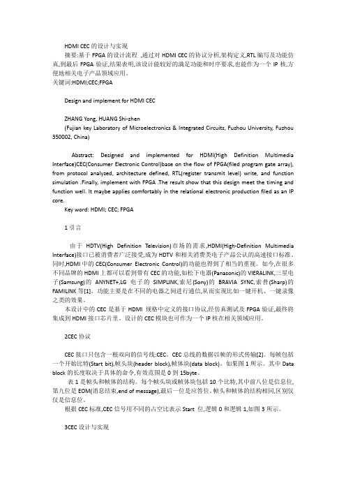
HDMI CEC的设计与实现摘要:基于FPGA的设计流程,通过对HDMI CEC的协议分析,架构定义,RTL编写及功能仿真,到最后FPGA验证,结果表明,该设计能较好的满足功能和时序要求,也能作为一个IP核,方便地相关电子产品领域应用。
关键词:HDMI;CEC;FPGADesign and implement for HDMI CECZHANG Yong, HUANG Shi-zhen(Fujian key Laboratory of Microelectronics & Integrated Circuits, Fuzhou University, Fuzhou 350002, China)Abstract: Designed and implemented for HDMI(High Definition Multimedia Interface)CEC(Consumer Electronic Control)base on the flow of FPGA(filed program gate array), from protocol analyzed, architecture defined, RTL(register transmit level) write, and function simulation .Finally, implement with FPGA .The result show that this design meet the timing and function well. It maybe applies comfortably in the relational electronic production filed as an IP core.Key word: HDMI; CEC; FPGA1引言由于HDTV(High Definition Television)市场的需求,HDMI(High-Definition Multimedia Interface)接口已被消费者广泛接受,成为HDTV和相关消费类电子产品公认的高速接口标准。
Rockchip Pin-Ctrl 开发指南发布版本:1.0日期:2016.07前言概述产品版本读者对象本文档(本指南)主要适用于以下工程师:技术支持工程师软件开发工程师修订记录目录1Pin-Ctrl配置............................................................................................... 1-11.1驱动文件与DTS配置.............................................................................. 1-11.2Iomux 配置........................................................................................ 1-21.3驱动强度配置 ....................................................................................... 1-31.4上下拉配置.......................................................................................... 1-41.5常见问题............................................................................................. 1-5 2GPIO使用 .................................................................................................. 2-12.1DTS配置与代码使用 .............................................................................. 2-12.2GPIO中断 .......................................................................................... 2-12.3GPIO常见问题..................................................................................... 2-21Pin-Ctrl配置pinctrl部分主要包括mux,驱动强度,上下拉配置等。
HDMI驱动模块开发HDMI Rx驱动模块开发⼀硬件电路1.1 HDMI 连接接⼝1.2SIL9135A芯⽚与connector通信的信号:1.2.1 数据输⼊:输⼊TMDS信号4路,3路数据,1路时钟;1.2.2 热插拔:5V与HDP1.2.3 读取DDC(Display Data Channel)数据: 通过SDA,SCL读取EDID;1.2.4 CEC(Consumer Electronics Control)消费电⼦控制通道:在源与宿之间传递控制信息,时钟与数据都通过1线传输。
如遥控器控制了电视,通过CEC来控制机顶盒的⼯作。
这⾥是通过编码器控制信号源。
与编码芯⽚:1.2.5 视频输出:时钟,⾏/场信号,16根数据信号1.2.6 ⾳频输出:I2S: (Inter-IC Sound Bus)1根位时钟信号,1根帧同步信号(WS),4根数据信号;1根静⾳控制信号,外部时钟信号?帧同步信号的频率等于采样频率SCLK的频率=2×采样频率×采样位数SPDIF(Sony/Philip Digital Interface):同轴⾳频接⼝;双相标记编码技术,只使⽤⼀条传输导线;MCLK1.2.7 中断输出:⼀根中断输出信号线;⼆基本功能2.1 热插拔检测HDMI没有插⼊时,CNW5602的HDP信号为⾼电平3.3V;插⼊后,变为conector的HDP电平,应该为低电平;CNW5602检测热插拔事件。
2.2 DDC数据读写2.2.1 CNW5602写EDID:读取EDID⽂件;通过I2C写⼊EDID数据;触发信号源读取。
2.2.2 信号源读取EDID:HDCP(数字内容保护)信源确认插⼊;通过DDC通道读取EDID。
2.2.3 HDMI芯⽚与驱动需要对EDID执⾏的处理逻辑?/doc/91aedb3b87c24028915fc328.html /ARTICLE_IMAGES/200804/20080425_HA_DT_HP_30.PDF?SOURCES=DOWNLOADEDID(Extended Display Identification DA TA,即扩展显⽰识别数据)数据为128Byte的倍数,规定数字电视显⽰的格式,也规定数字视频信号和数字⾳频信号。
HDMI Input/Output FMC module with Camera Interface (FMC-HDMI-CAM) Getting Started:1. Navigate to the following product page: /fmc-hdmi-cam2. Click on the “Support Files & Downloads” button3. Login to the web site:a. If you already have an account, specify credentials and click the Login buttonb. To create a new account, specify a valid e-mail and click the Register button4. Download the FMC-HDMI-CAM Getting Started Guide5. Extract all files and follow instructions in the extracted Getting Started GuideFeatures:• HDMI Input: HDMI Input, featuring Analog Devices ADV7611• HDMI Output: HDMI Output, featuring Analog Devices ADV7511• Video Clock: Video clock synthesizer, featuring TI CDCE913•Camera Input:Camera connector, supporting several optional camera modulesLICENSE AGREEMENTTHE AVNET DESIGN KIT (“DESIGN KIT” OR “PRODUCT”) AND ANY SUPPORTING DOCUMENTATION (“DOCUMENTATION” OR “PRODUCT DOCUMENTATION”) IS SUBJECT TO THIS LICENSE AGREEMENT (“LICENSE”). USE OF THE PRODUCT OR DOCUMENTATION SIGNIFIES ACCEPTANCE OF THE TERMS AND CONDITIONS OF THIS LICENSE. THE TERMS OF THIS LICENSE AGREEMENT ARE IN ADDITION TO THE AVNET CUSTOMER TERMS AND CONDITIONS, WHICH CAN BE VIEWED AT . THE TERMS OF THIS LICENSE AGREEMENT WILL CONTROL IN THE EVENT OF A CONFLICT.1. Limited License. Avnet grants You, the Customer, (“You” “Your” or “Customer”) a limited, non-exclusive, non-transferable, license to: (a) use the Product for Your own internal testing, evaluation and design efforts at a single Customer site; (b) create a singlederivative work based on the Product using the same semiconductor supplier product or product family as used in the Product; and (c) make, use and sell the Product in a single production unit. No other rights are granted and Avnet and any other Product licensor reserves all rights not specifically granted in this License Agreement. Except as expressly permitted in this License, neither the Design Kit, Documentation, nor any portion may be reverse engineered, disassembled, decompiled, sold, donated, shared, leased, assigned, sublicensed or otherwise transferred by Customer. The term of this License is in effect until terminated. Customer may terminate this license at any time by destroying the Product and all copies of the Product Documentation.2. Changes. Avnet may make changes to the Product or Product Documentation at any time without notice. Avnet makes no commitment to update or upgrade the Product or Product Documentation and Avnet reserves the right to discontinue the Productor Product Documentation at any time without notice.3. Limited Warranty. ALL PRODUCTS AND DOCUMENTATION ARE PROVIDED “AS IS” WITHOUT WARRANTY OF ANY KIND. AVNET MAKES NO WARRANTIES, EITHER EXPRESS OR IMPLIED, WITH RESPECT TO THE PRODUCTS AND DOCUMENTATION PROVIDEDHEREUNDER. AVNET SPECIFICALLY DISCLAIMS THE IMPLIED WARRANTIES OF MERCHANTABILITY AND FITNESS FOR A PARTICULAR PURPOSE AND ANY WARRANTY AGAINST INFRINGEMENT OF ANY INTELLECTUAL PROPERTY RIGHT OF ANY THIRD PARTY WITH REGARD TO THE PRODUCTS AND DOCUMENTATION.4. LIMITATIONS OF LIABILITY. CUSTOMER SHALL NOT BE ENTITLED TO AND AVNET WILL NOT LIABLE FOR ANY INDIRECT, SPECIAL, INCIDENTAL OR CONSEQUENTIAL DAMAGES OF ANY KIND OR NATURE, INCLUDING, WITHOUT LIMITATION, BUSINESSINTERRUPTION COSTS, LOSS OF PROFIT OR REVENUE, LOSS OF DATA, PROMOTIONAL OR MANUFACTURING EXPENSES, OVERHEAD, COSTS OR EXPENSES ASSOCIATED WITH WARRANTY OR INTELLECTUAL PROPERTY INFRINGEMENT CLAIMS, INJURY TO REPUTATION OR LOSS OF CUSTOMERS, EVEN IF AVNET HAS BEEN ADVISED OF THE POSSIBILITY OF SUCH DAMAGES. THE PRODUCTS AND DOCUMENTATION ARE NOT DESIGNED, AUTHORIZED OR WARRANTED TO BE SUITABLE FOR USE IN MEDICAL, MILITARY, AIR CRAFT, SPACE OR LIFE SUPPORT EQUIPMENT NOR IN APPLICATIONS WHERE FAILURE OR MALFUNCTION OF THE PRODUCTS CAN REASONABLY BE EXPECTED TO RESULT IN A PERSONAL INJURY, DEATH OR SEVERE PROPERTY OR ENVIRONMENTAL DAMAGE. INCLUSION OR USE OF PRODUCTS IN SUCH EQUIPMENT OR APPLICATIONS, WITHOUT PRIOR AUTHORIZATION IN WRITING OF AVNET, IS NOT PERMITTED AND IS AT CUSTOMER’S OWN RISK. CUSTOMER AGREES TO FULLY INDEMNIFY AVNET FOR ANY DAMAGES RESULTING FROM SUCH INCLUSION OR USE.5. LIMITATION OF DAMAGES. CUSTOMER’S RECOVERY FROM AVNET FOR ANY CLAIM SHALL NOT EXCEED CUSTOMER’S PURCHASE PRICE FOR THE PRODUCT GIVING RISE TO SUCH CLAIM IRRESPECTIVE OF THE NATURE OF THE CLAIM, WHETHER IN CONTRACT,TORT, WARRANTY, OR OTHERWISE.6. INDEMNIFICATION. AVNET SHALL NOT BE LIABLE FOR AND CUSTOMER SHALL INDEMNIFY, DEFEND AND HOLD AVNET HARMLESS FROM ANY CLAIMS BASED ON AVNET’S COMPLIANCE WITH CUSTOMER’S DESIGNS, SPECIFICATIONS OR INSTRUCTIONS,OR MODIFICATION OF ANY PRODUCT BY PARTIES OTHER THAN AVNET, OR USE IN COMBINATION WITH OTHER PRODUCTS.7. U.S. Government Restricted Rights. The Product and Product Documentation are provided with “RESTRICTED RIGHTS.” If the Product and Product Documentation and related technology or documentation are provided to or made available to the United StatesGovernment, any use, duplication, or disclosure by the United States Government is subject to restrictions applicable to proprietary commercial computer software as set forth in FAR 52.227-14 and DFAR 252.227-7013, et seq., its successor and other applicable laws and regulations. Use of the Product by the United States Government constitutes acknowledgment of the proprietary rights of Avnet and any third parties. No other governments are authorized to use the Product without written agreement of Avnet and applicable third parties.8. Ownership. Licensee acknowledges and agrees that Avnet or Avnet’s licensors are the sole and exclusive owner of all Intellectual Property Rights in the Licensed Materials, and Licensee shall acquire no right, title, or interest in the Licensed Materials,other than any rights expressly granted in this Agreement.9. Intellectual Property. All trademarks, service marks, logos, slogans, domain names and trade names (collectively “Marks”) are the properties of their respective owners. Avnet disclaims any proprietary interest in Marks other than its own. Avnet and AVdesign logos are registered trademarks and service marks of Avnet, Inc. Avnet’s Marks may be used only with the prior written permission of Avnet, Inc.10. General. The terms and conditions set forth in the License Agreement or at will apply notwithstanding any conflicting, contrary or additional terms and conditions in any purchase order, sales acknowledgement confirmation or otherdocument. If there is any conflict, the terms of this License Agreement will control. This License may not be assigned by Customer, by operation of law, merger or otherwise, without the prior written consent of Avnet and any attempted or purported assignment shall be void. Licensee understands that portions of the Licensed Materials may have been licensed to Avnet from third parties and that such third parties are intended beneficiaries of the provisions of this Agreement. In the event any of the provisions of this Agreement are for any reason determined to be void or unenforceable, the remaining provisions will remain in full effect.This constitutes the entire agreement between the parties with respect to the use of this Product, and supersedes all prior or contemporaneous understandings or agreements, written or oral, regarding such subject matter. No waiver or modification is effective unless agreed to in writing and signed by authorized representatives of both parties. The obligations, rights, terms and conditions shall be binding on the parties and their respective successors and assigns. The License Agreement is governed by and construed in accordance with the laws of the State of Arizona excluding any law or principle, which would apply the law of any other jurisdiction. The United Nations Convention for the International Sale of Goods shall not apply.Copyright © 2015, Avnet, Inc. All rights reserved. Published by Avnet Electronics Marketing, a group of Avnet, Inc. Avnet, Inc. disclaims any proprietary interest or right in anytrademarks, service marks, logos, domain names, company names, brands, product names, or other form of intellectual property other than its own. AVNET and the AV logos areregistered trademarks of Avnet, Inc. LIT #QSC-AES-FMC-HDMI-CAM-G-V1。
HDMI Rx驱动模块开发一硬件电路
1.1 HDMI 连接接口
1.2SIL9135A芯片
与connector通信的信号:
1.2.1 数据输入:输入TMDS信号4路,3路数据,1路时钟;
1.2.2 热插拔:5V与HDP
1.2.3 读取DDC(Display Data Channel)数据: 通过SDA,SCL读取EDID;
1.2.4 CEC(Consumer Electronics Control)消费电子控制通道:
在源与宿之间传递控制信息,时钟与数据都通过1线传输。
如遥控器控制了电视,通过CEC来控制机顶盒的工作。
这里是通过编码器控制信号源。
与编码芯片:
1.2.5 视频输出:时钟,行/场信号,16根数据信号
1.2.6 音频输出:
I2S: (Inter-IC Sound Bus)
1根位时钟信号,1根帧同步信号(WS),4根数据信号;
1根静音控制信号,外部时钟信号?
帧同步信号的频率等于采样频率
SCLK的频率=2×采样频率×采样位数
SPDIF(Sony/Philip Digital Interface):
同轴音频接口;
双相标记编码技术,只使用一条传输导线;
MCLK
1.2.7 中断输出:一根中断输出信号线;
二基本功能
2.1 热插拔检测
HDMI没有插入时,CNW5602的HDP信号为高电平3.3V;
插入后,变为conector的HDP电平,应该为低电平;
CNW5602检测热插拔事件。
2.2 DDC数据读写
2.2.1 CNW5602写EDID:
读取EDID文件;
通过I2C写入EDID数据;
触发信号源读取。
2.2.2 信号源读取EDID:HDCP(数字内容保护)
信源确认插入;
通过DDC通道读取EDID。
2.2.3 HDMI芯片与驱动需要对EDID执行的处理逻辑?
/ARTICLE_IMAGES/200804/20080425_HA_DT_HP_30.PDF?SOURC
ES=DOWNLOAD
EDID(Extended Display Identification DA TA,即扩展显示识别数据)
数据为128Byte的倍数,规定数字电视显示的格式,也规定数字视频信号和数字音频信号。
2.2.4 两个接口对寄存器的访问:
DDC I2C(0x74,100kHz)可以访问HDCP的内容操作寄存器和SIL9135A的公共寄存器;
本地I2C(0x60/0x68,400kHz)可以访问SIL9135A的公共寄存器和通用寄存器。
参考:/wiki/Extended_display_identification_data
/download/HDMISpecification13a.pdf
/
/wiki/HDMI%E6%8E%A5%E5%8F%A3
2.3音视频信号输入处理
2.3.1TMDS对音视频的数据发送时序控制
TMDS(Time Minimized Differential Signal)
在一个时钟周期内,每个TMDS通道都能传送10bit的数据流。
三个传输阶段:
视频数据传输周期:8bit为单元的视频数据。
(HDMI1.3版本前每个像素采用24bit)
控制传输周期:2bit为单元的控制数据
数据包传输周期:4bit为单元的数据包,包含音频数据和附加信息数据,例如纠错码等
TMDS数据发送时序结构
音频数据在HSYNC和视频数据之间。
2.3.2 TMDS差分信号线的视频数据
TMDS对每个像素点中的RGB三原色分别按8bit编码
2.4 音频信号输出处理
I2S:
LRCLK(WS)控制立体声数据传输;
高电平,传输左声道,低电平传输右声道。
数据的最高位总是出现在也就是一帧开始后的第2个SCLK脉冲处。
发送端与接收端可以具有不同的有效位数,低位丢弃。
I2S数据格式:
左对齐:较少使用,即飞利浦规定的格式;
右对齐:普通格式,也叫日本格式
SPDIF(Sony/Philip Digital Interface):
双相标记编码技术,只使用一条传输导线;
传输时钟信号和音轨开始标记、资料辨认信息和时间等数据信号;
2.5 视频信号输出处理
2.5.1 视频信号的处理流程
2.5.2 视频信号的检测时机
SCDT and CKDT register bits to determine when active video is being received by the chip.
2.5.3 视频信号的切断控制
2.5.4 输出端口的数据规范:
数据的采样时双采样。
YUV4:2:2的采样规范:
两个像素样本为一组,前一样本的RGB用YU,后一样本的RGB用YV表示。
YUV4:2:0的采样规范:
四个像素样本为一组,分为两行子组。
前一行子组用前一样本的YU表示,后一行子组用后一样本的YV表示。
YUV4:2:2的接口格式(16bits):
2.6 CEC控制
三设计与实现。